the Creative Commons Attribution 4.0 License.
the Creative Commons Attribution 4.0 License.
 | 21 Apr 2022
Assessment of force control for surface finishing – an experimental comparison between Universal Robots UR10e and FerRobotics active contact flange
Hubert Gattringer
Andreas Mueller
Robotic surface treatment is already broadly used in the manufacturing industry because it guarantees repeatable high-quality surfaces at short production time. Such a robotic solution, with an accurate control of the applied force on a surface, requires a robot that is either equipped with a force/torque sensor or, alternatively, with a force compliance device. However, without a direct performance comparison, it is hard to know which is the best option for a specific surface treatment operation. Compared to the evaluation of the robot positioning accuracy, using the ISO 9283 test, no standardized test for the quality assessment of robot force control exists yet. In trying to fill this gap, this paper introduces different test scenarios and a test set-up for such a force control quality assessment. As a start, the force control of a Universal Robots UR10e model and a FerRobotics ACF-K 109/04 model are experimentally evaluated. The latter is an external device with controlled force/compliance characteristics, which is referred to as an active contact flange (ACF). For the performance comparison, an ATI force/torque sensor, which is mounted below a work piece, measures the applied force either by the UR or by the ACF. The measured forces are further transformed to the UR tool centre point (TCP) frame. Then, only the z component of the force, or rather the normal force, is relevant for surface treatment and hence important for the evaluation. For each test case, the average value of five test runs with the same parameters is used for the assessment. Results for both the UR and ACF force control are presented for varying desired contact velocities and desired forces. These results indicate the advantage of the ACF-K 109/04 over the UR10e force control for highly dynamic force control scenarios.
- Article
(9786 KB) - Full-text XML
- BibTeX
- EndNote


Surface finishing operations like grinding, sanding, or polishing are common in many industrial sectors, for example, in the automotive industry or aerospace (Iglesias et al., 2015). Previously, such operations were mainly carried out by people. These days, industrial robots are used more and more for the reduction of labour and further increase in the efficiency and quality. Force-controlled robots are even used for machining operations. Active force control is limited by the control bandwidth, which limits its use to applications with low dynamics. On the other hand, devices that actively control the passive compliance allow for the generation of a prescribed passive (physical) compliance. They represent alternatives to force-controlled robots using force/torque sensors. There are a number of commercial, so-called compliance devices, that can be used for surface treatment, such as the FerRobotics active contact flange (ACF; FerRobotics Compliant Robot Technology GmbH, 2021a), ATI PCFC (ATI Industrial Automation, 2021b), the Robotiq sanding kit, or the force compliance devices of PushCorp (PushCorp Inc., 2021).
Passive compliance tools (with open-loop control) set the desired force via external, manually adjusted air pressure regulators. The force for a specific pressure is constant, provided that the tool inclination stays the same for the whole operation. In contrast, active compliance devices rely on internal closed-loop feedback control to actively control the compliance, and to compensate for gravity, independent of the tool orientation.
From an application perspective, in order to decide whether the active compliance provided by an industrial robot is sufficient, or if controlled compliance devices are necessary, it is crucial to perform representative tests for comparative performance assessments. For example, Winkler and Suchý (2013) use a triangular contour to assess the quality of the hybrid position/force controller of a robot. However, there is neither a standardized test nor are there standardized performance measures. In this paper, a testing procedure and assessment criteria that allow for an objective comparison are proposed. The test regime is applied to the UR10e (Universal Robots A/S, 2021) and the ACF-K 109/04 (FerRobotics Compliant Robot Technology GmbH, 2021b), which is an active compliance tool. A detailed explanation of the test scenarios, the test set-up, including computer-aided design (CAD) data, and all results are publicly available on the GitHub repository of JKU Linz – Institute of Robotics. This enables the reproduction of the results for the presented two systems but also to perform these tests for other systems.
Figure 1 visualizes the desired characteristics of a robotic surface finishing system. Thus, robots with or without force compliance tools should do the following:
-
have a high performance,
-
exhibit a high robustness,
-
be simple to programme, and
-
show flexibility.
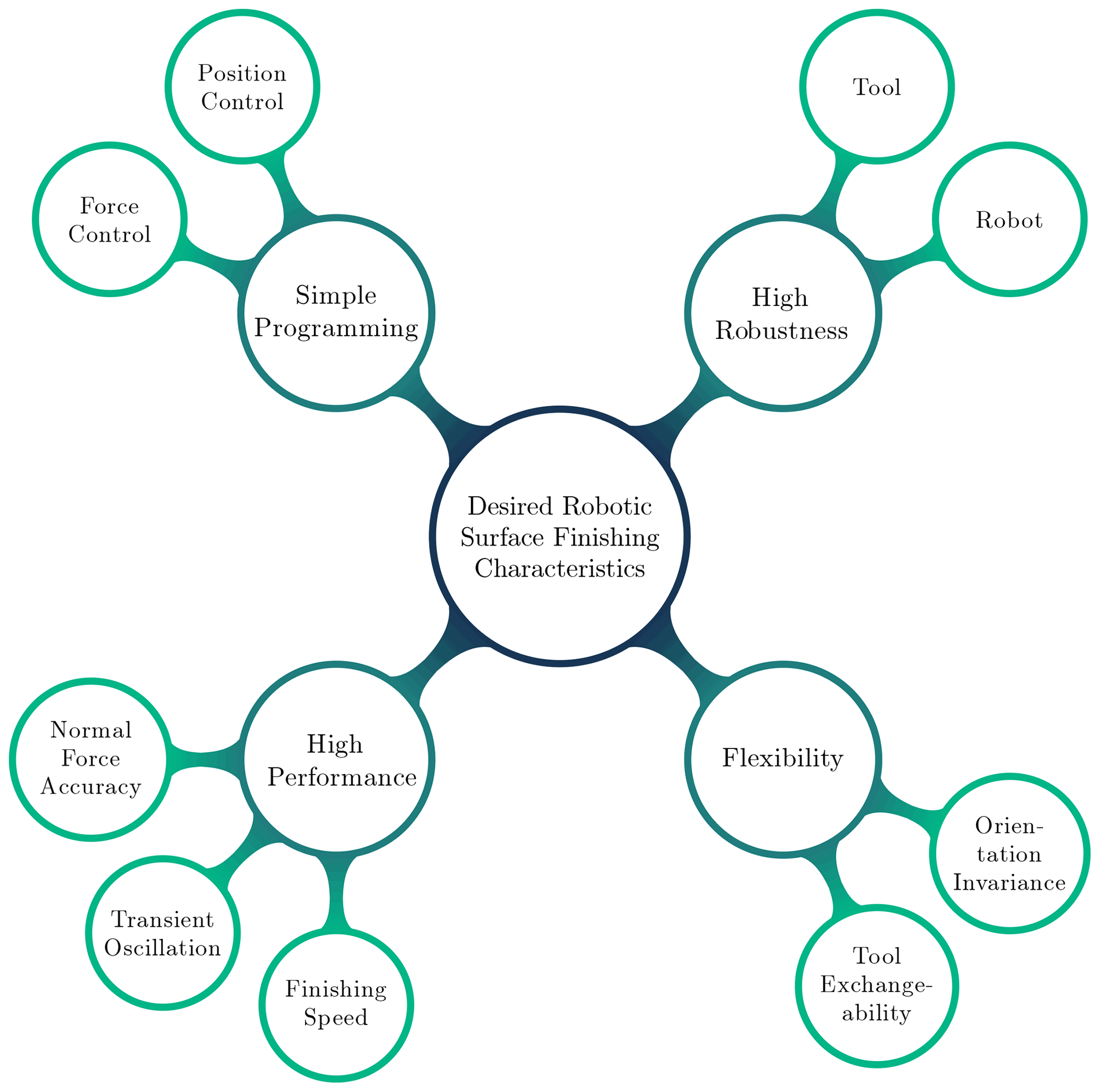
First, a high performance is desired. In the context of surface treatment, this means a high accuracy of normal forces, together with a short settling time and short transient oscillation, to be able to achieve high-quality surfaces. A high finishing speed assures short cycle times.
Second, both the robot and the tool should have high robustness to endure possible high, normal, and shear forces. High forces could occur during normal operation (e.g. grinding and deburring) or during a collision, in the worst-case scenario.
Third, the programming complexity for following a desired path of the tool centre point (TCP), which depends on the used robotic set-up (robot and tool), should be low. Using a force compliance tool for surface treatment might simplify the planning of the TCP trajectory because the robot just needs to operate in position control mode. In this case, the tool is responsible for applying the desired normal force while compensating for position deviations of the robot. By contrast, without the force compliance tool, the robot must operate in force control mode, and task-dependent controller settings are required for appropriate control of the normal force while following the TCP path.
The fourth desired characteristic is flexibility, which mainly implies orientation invariance and tool exchangeability. If the former criterion is fulfilled, then a desired force can be applied independently of the tool inclination. So, a different end effector orientation due to a changed robot trajectory or an inclined tool mounting position would have no negative effect. The latter criterion describes if or how easily a robot tool can be exchanged to replace a broken hardware or be ready for another task such as, for example, switching from grinding to polishing.
For machining operations via robots, a safe contact or rather a compliant behaviour between the robot and its environment must be ensured. For example, the control of the active compliance is possible via impedance control (Siciliano and Villani, 1999), which is shown in Fig. 2.
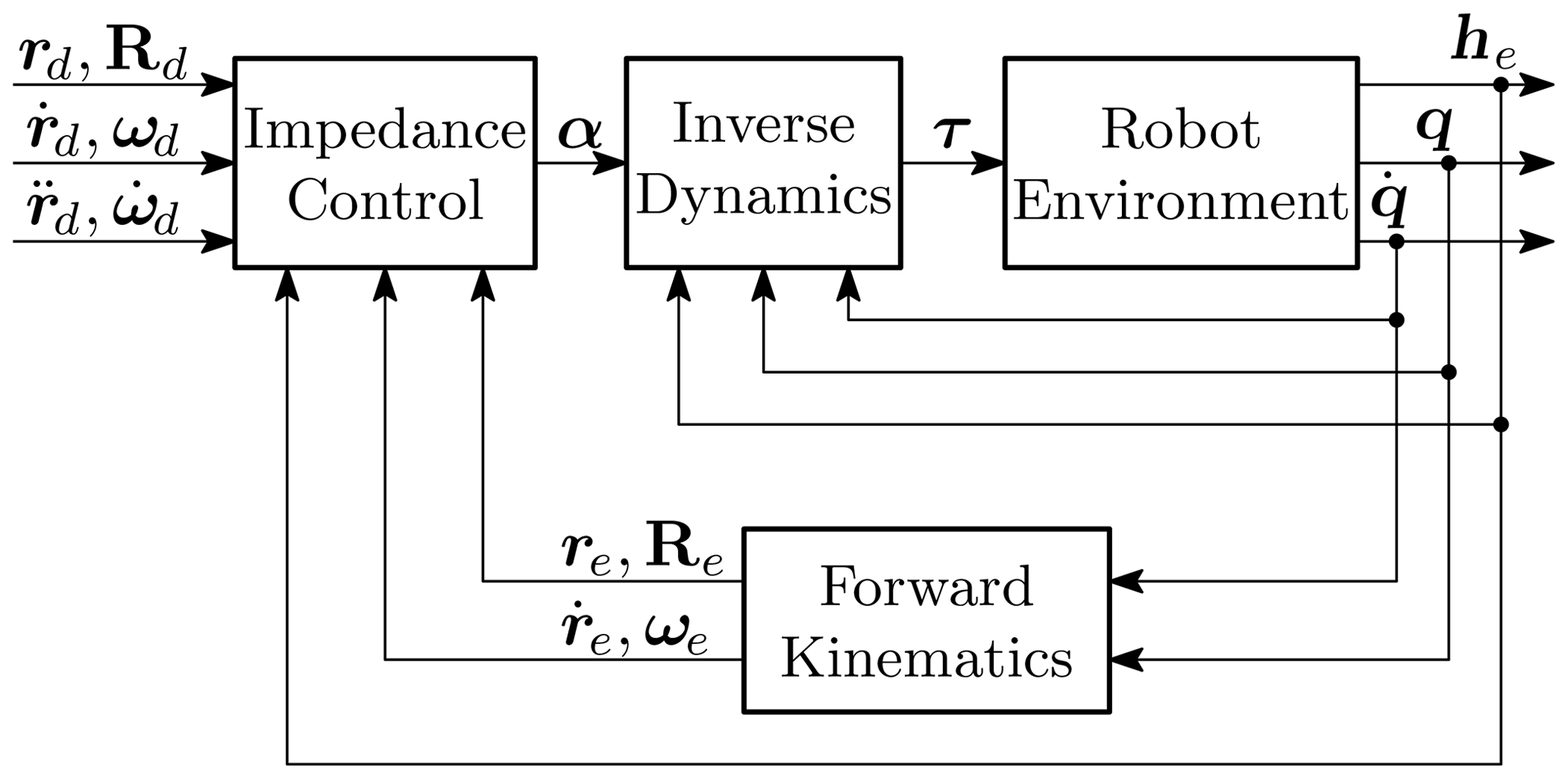
Figure 2Block diagram of impedance control (adapted from Siciliano and Villani, 1999).
The apparent compliance is achieved by a controlled evasive motion as a response to the measured forces. This is obtained within the control cycle time. The impedance controller uses the desired trajectory, the measured joint position q and velocity , and the measured contact forces and torques at the end effector he∈ℝ6 as input. Thereby, the desired trajectory is given by the corresponding position rd∈ℝ3, orientation Rd∈SO(3), and their derivatives up to translational acceleration and angular acceleration . As described in Siciliano and Villani (1999), the output of the impedance controller α∈ℝ6 is computed, so that together with the inverse dynamics control law, the robot behaviour is equivalent to a mass–spring–damper system. Due to the required inverse dynamics, impedance control is a model-based control scheme and requires an accurate dynamic model of the robot (Bremer, 2008).
On the other hand, active compliance devices actively control the passive compliance. Using such a device decouples the robot from the contact process and hence from contact forces at the end effector, occurring during surface finishing operations for example. Such a decoupling simplifies robot control to just position control due to the independence from the environment.
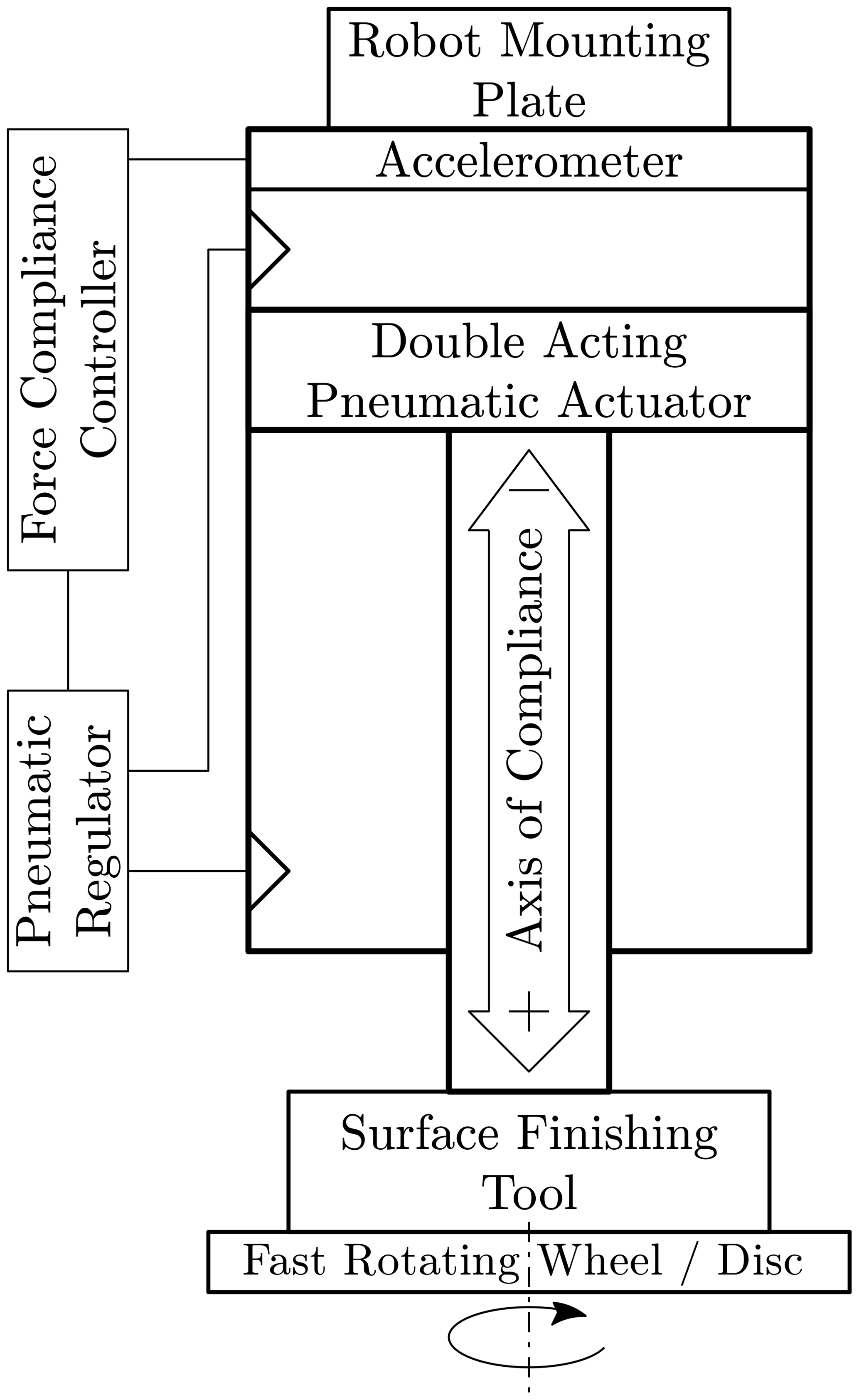
Figure 3 shows the working principle of an active force compliance device. Such a device can basically be a double-acting pneumatic actuator with additional sensors. A surface finishing tool is somehow attached to the cylinder piston, which represents the axis of compliance. The force compliance controller continuously adjusts the pressure via the pneumatic regulator (closed loop) to apply the desired force while compensating for gravity using the accelerometer measurement. Some manufacturers, e.g. PushCorp Inc. (2021), additionally attach a load cell to the double-acting pneumatic actuator to directly read the force applied by the actuator. In contrast, FerRobotics Compliant Robot Technology GmbH (2021a) accurately calibrates each ACF for different orientations before product delivery to be able to apply the desired force independently from the orientation.
Figure 4 shows the test set-up with Universal Robots UR10e, a robot tool, and a force/torque sensor as the main components. Different profiles (e.g. ramp profile) allow for the comparison of the UR/ACF force control for various test cases. The force/torque sensor is mounted at the bottom of a work piece for measuring the real forces acting on the work piece. The robot tool itself consists of the ACF, an iron reel, and an additional adjustable weight for the simulation of a real robot tool (e.g. angle grinder), which would normally be mounted on the ACF-K (FerRobotics Compliant Robot Technology GmbH, 2021b) instead of the reel. The ACF requires a separate control box for operation.
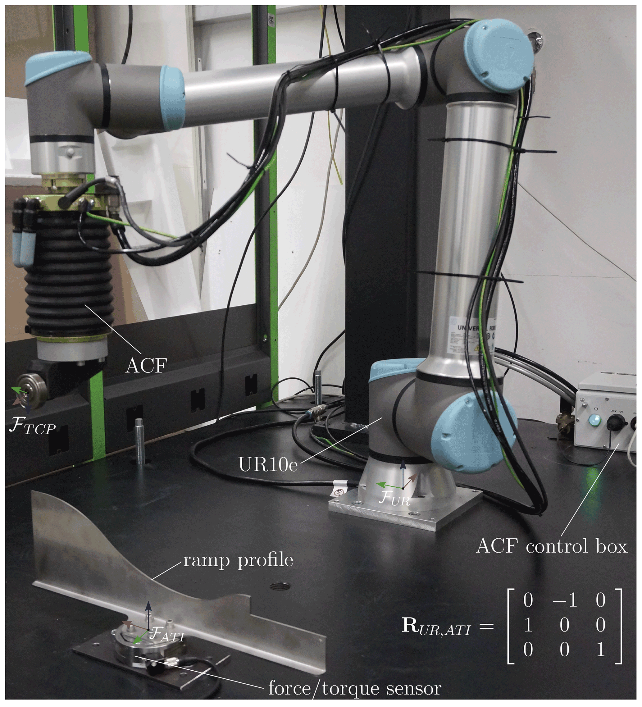
The ATI Delta SI-660-60 (ATI Industrial Automation, 2021a) of Fig. 4 serves as force/torque sensor for the assessment. It has a sensing range up to 1980 N and a resolution of 0.25 N for normal forces, i.e. forces Fz. The ATI forces are read with a sample time of 800 µs using a B&R analogue input module of the B&R X20 CPU (B&R Industrial Automation GmbH, 2021a, b).
4.1 Universal Robots
The Universal Robots UR10e model (Universal Robots A/S, 2021) is a collaborative robot with 6 degrees of freedom (DOF). It allows a maximal payload of 10 kg and has a built-in force/torque sensor. According to the specification, the UR10e has a control frequency of 500 Hz (2 ms sampling time) and allows force control up to 100 N, with an accuracy of 5.5 N.
Surface finishing requires the control of the normal force. Hence, for the UR force control, it is necessary to set the z axis of the TCP frame ℱTCP as the compliant axis. This means that the force control task frame must be equal the current TCP frame. Consequently, the task frame must be continuously updated to guarantee this even during movement. The UR further allows the modification of the force control via the parameters of damping (default 0.005) and gain scaling (default 1). The damping parameter describes the UR speed decrease behaviour in the case of no contact with a work piece. In detail, using a damping parameter greater than zero leads to a deceleration if no force is present. The gain scaling parameter represents the gain of the force controller. A larger value than the default value of 1 leads to a more aggressive controller and might even cause instability.
4.2 Active contact flange
In contrast to the UR, the ACF is a 1 DOF mechatronic actuator and sensor element. This enables a robot with a mounted ACF to apply a consistent contact force on a surface, even if it is not equipped with a force/torque sensor. The product to be tested is an ACF-K 109/04, with a stroke of 35.5 mm and a maximal applicable force of 100 N (FerRobotics Compliant Robot Technology GmbH, 2021b).

Figure 5Force evolution depending on ACF operation parameters (adapted from FerRobotics Compliant Robot Technology GmbH, 2021c).
Figure 5 shows an exemplary ACF force evolution for a desired force Fd≥0, considering its operation parameters. The operation parameters are the ramp time tramp≥0 and zero force , which describe a ramp used for ramping up from force Fzero to Fd within time tramp. Without contact to a work piece, the ACF initially applies a force of Fzero. As soon as contact is detected, the ACF ramps up to force Fd within the defined time. If tramp is zero, then the ramp is deactivated, and the ACF always applies Fd.
This paper assesses three test scenarios (ramp profile, direct sensor contact, and straight profile) for the UR/ACF force control comparison. Due to the hard contact of the reel with a metal profile (metal-to-metal contact), quite high forces can result. The considered force control parameters are gain scaling gain = 1 and damping d=0 for the UR and tramp = 0 s (deactivated force ramp) for the ACF. Tests with many more parameter values are presented on the GitHub repository of JKU Linz – Institute of Robotics (2022).
5.1 Ramp profile
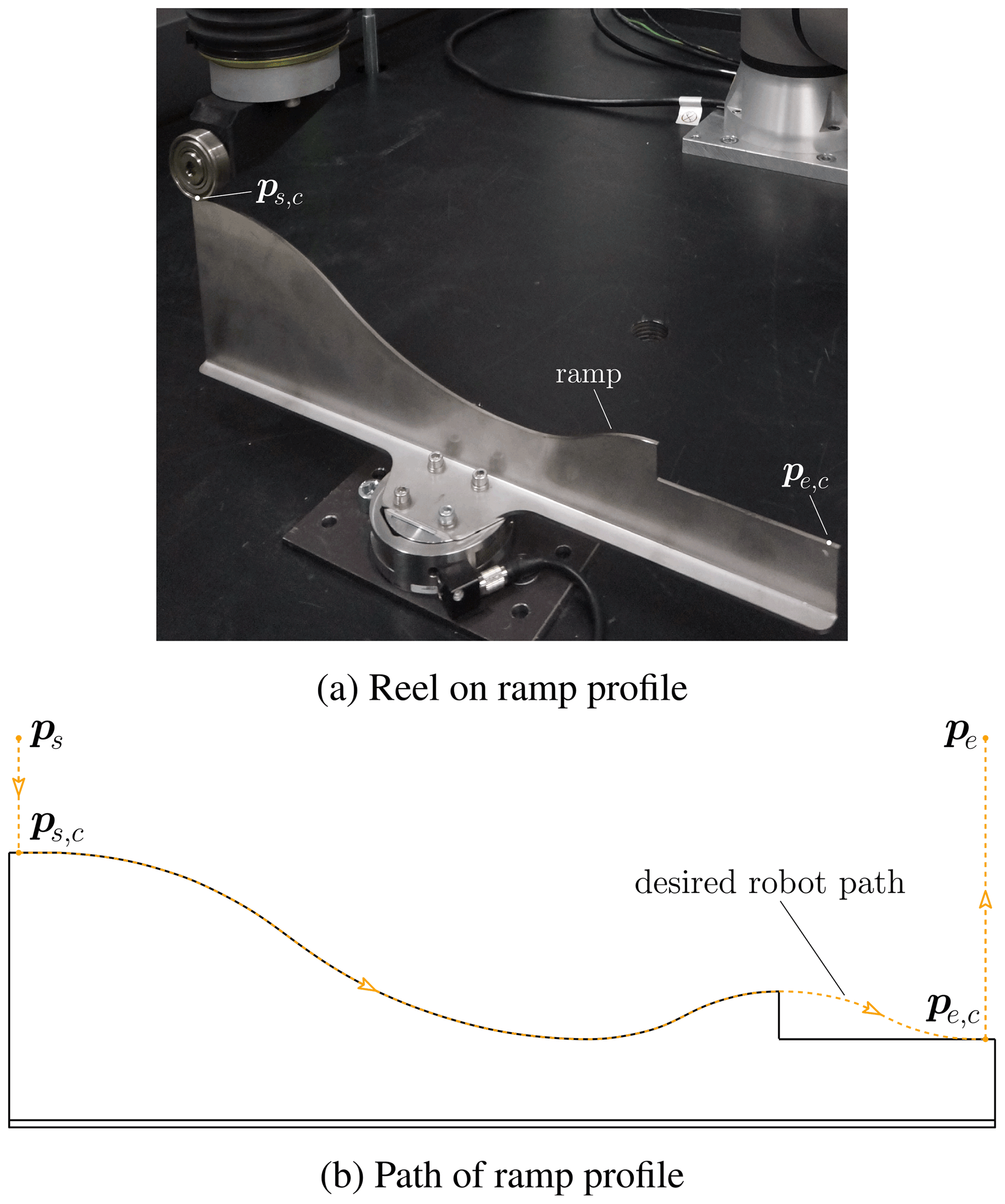
The ramp profile of Fig. 6 involves various orientation changes and a ramp (or rather a jump) that will lead to a takeoff of the robot end-effector. Due to these fast orientation changes, highly dynamic force control is required for suitable performance. The TCP velocity is limited to 0.25 m s−1.
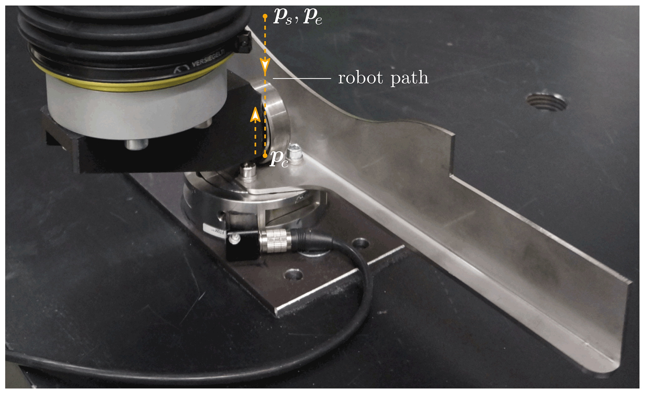
5.2 Direct sensor contact
The direct sensor contact test, shown in Fig. 7, is simply a vertical movement directly onto the force/torque sensor of Fig. 6a, using an end-effector velocity of 0.10 or 0.25 m s−1. Downwards, either the UR position or force control is used until the robot reaches the contact pose pc, where it stands still for approx. 6 s and applies the desired force. Upwards, the UR uses position control for all test cases. This test considers the maximum ACF/UR force of 100 N to evaluate how well the ACF and the UR can handle such a high force.
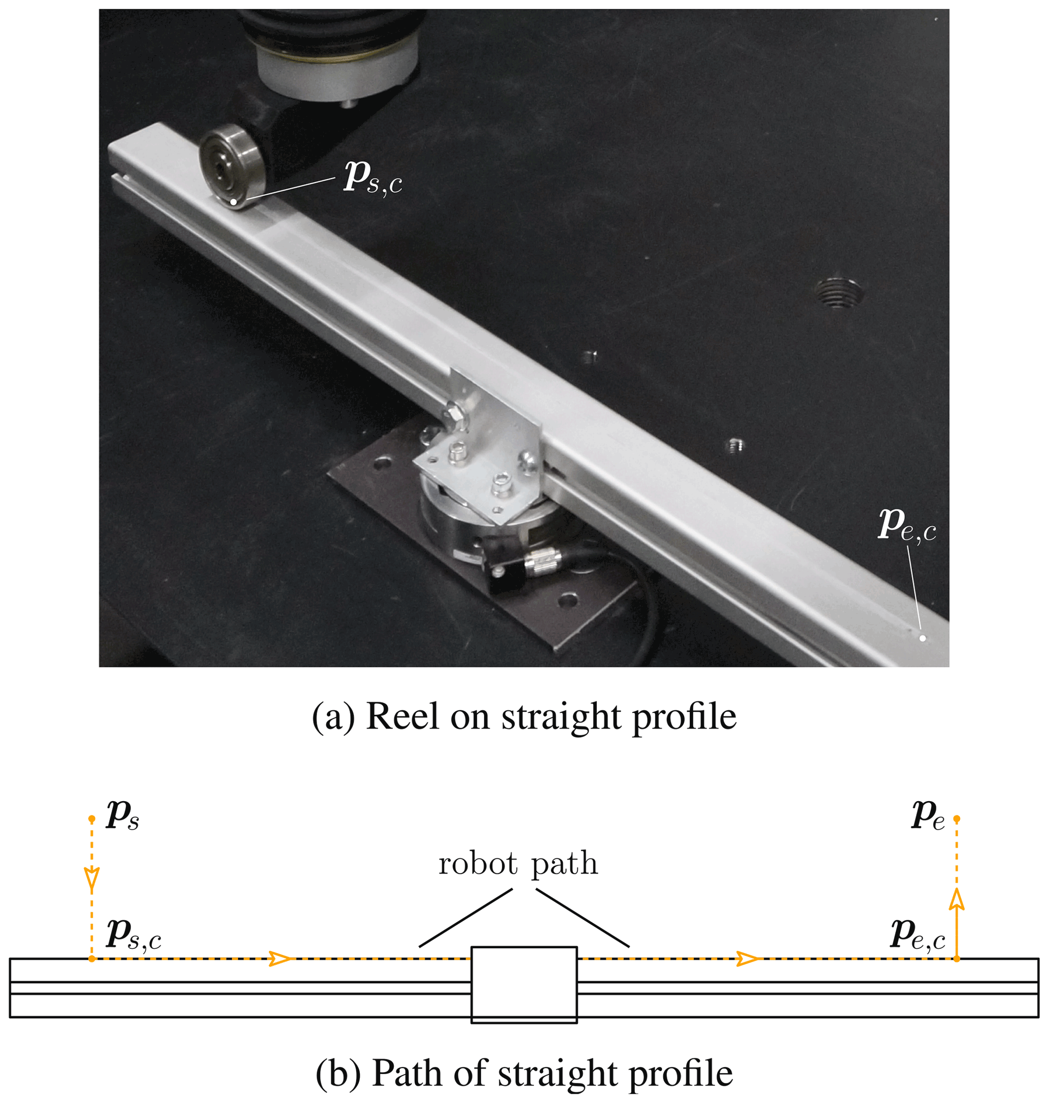
5.3 Straight profile
Figure 8 shows the so-called straight profile, which is basically an aluminium profile, and it allows a movement speed up to 0.90 m s−1 due to its simple, straight shape. The length of the straight line is 0.53 m, which is approx. the total arc length of the ramp profile, to achieve a travel time like the other test case.
The assessment criteria are the deviation from the desired normal force, which should be applied to the work piece and the settling time to define the duration until the force error stays within a specified error band. If we consider a normal robot path to the surface of a work piece, then the normal force is equal the force Fz of the total force vector , represented in the TCP frame ℱTCP. However, the ATI force/torque sensor, shown in Fig. 4, measures the forces ATIF in its own frame ℱATI, and sampled with 800 µs, and further requires transformation to ℱTCP.
At first, the force vector is transformed to the UR base frame ℱUR, i.e. , and subsequently to ℱTCP, i.e. , using the actual TCP orientation. This orientation is represented by the rotation matrix and depends on joint coordinates q∈ℝ6. Therefore, the TCP orientation data must be sampled with 800 µs as well. However, the UR10e internally uses a sampling time of 2 ms, i.e. upsampling is required. PolyScope 5.9.1, the UR operating system, represents the TCP orientation as a rotation vector, which is a compact form of the axis–angle representation (Siciliano and Khatib, 2016). For simplified data upsampling, this representation can also be converted to roll–pitch–yaw angles (Siciliano and Khatib, 2016), which is a consecutive rotation order of z–y–x, with angles γ–β–α, without a singularity problem because the robot mainly rotates about the x axis with the roll angle α. Considering these angles, data upsampling from 2 ms to 800 µs is easily possible, for example, via piecewise cubic interpolation (Fritsch and Carlson, 1980). Consequently, it is feasible to transform the ATI forces to ℱTCP and to calculate the absolute z-force error as follows:
Respectively, this is valid for a single measurement value or for the whole force path. This can be further separated into the two time domains, as follows:
The former represents the first few seconds of the standstill at the beginning (start of contact at t=0) and is set to tc=3 s for both the ramp and the straight profiles and to tc=6 s for the direct sensor test. The latter considers the time between the start of movement tm≥tc and the end time te. These times are determined automatically, using the desired velocity of the robot path. For the evaluation, the maximum absolute force error and the mean absolute error with the corresponding standard deviation of both time domains are important.
In addition to the force error, the settling time tset is another important criterion for the force control assessment. It defines the duration until the error stays within the error band of ±10 N or rather ±10 % of the maximal force of ACF and UR. For each test case, the average of five test runs with same parameters is used for the assessment.
7.1 Ramp profile
Figure 9 shows the normal forces of ACF and UR10e at first contact with the ramp profile for a desired velocity of and a desired force of Fd=15 N. It can be seen in the detailed view of Fig. 9b that the ACF exhibits a much shorter transient oscillation compared to the UR.
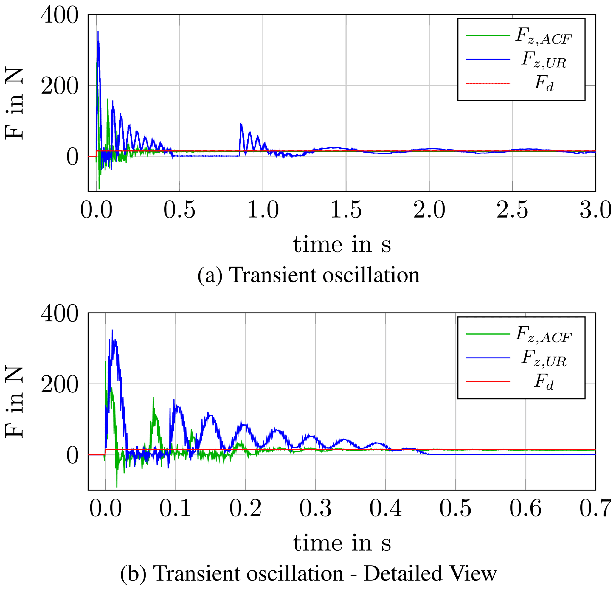
Figure 10 shows the force evolution of ACF and UR10e for a desired velocity of vd=0.25 m s−1 and desired forces of Fd=15 N and Fd=35 N. The orientation changes are challenging for both ACF and UR force control, and this partly leads to a loss of contact with the work piece. This particularly happens for the UR force control and causes force peaks when contact is regained. The effect of the jump is recognizable at a time of approx. t=6 s, with measured forces near zero for both ACF and UR, followed by another force peak with transient oscillation. However, the UR regains contact much later than the ACF. For the last 2 s of the trajectory, the robot should already stay constant at its end pose, but this is delayed due to the UR force control.
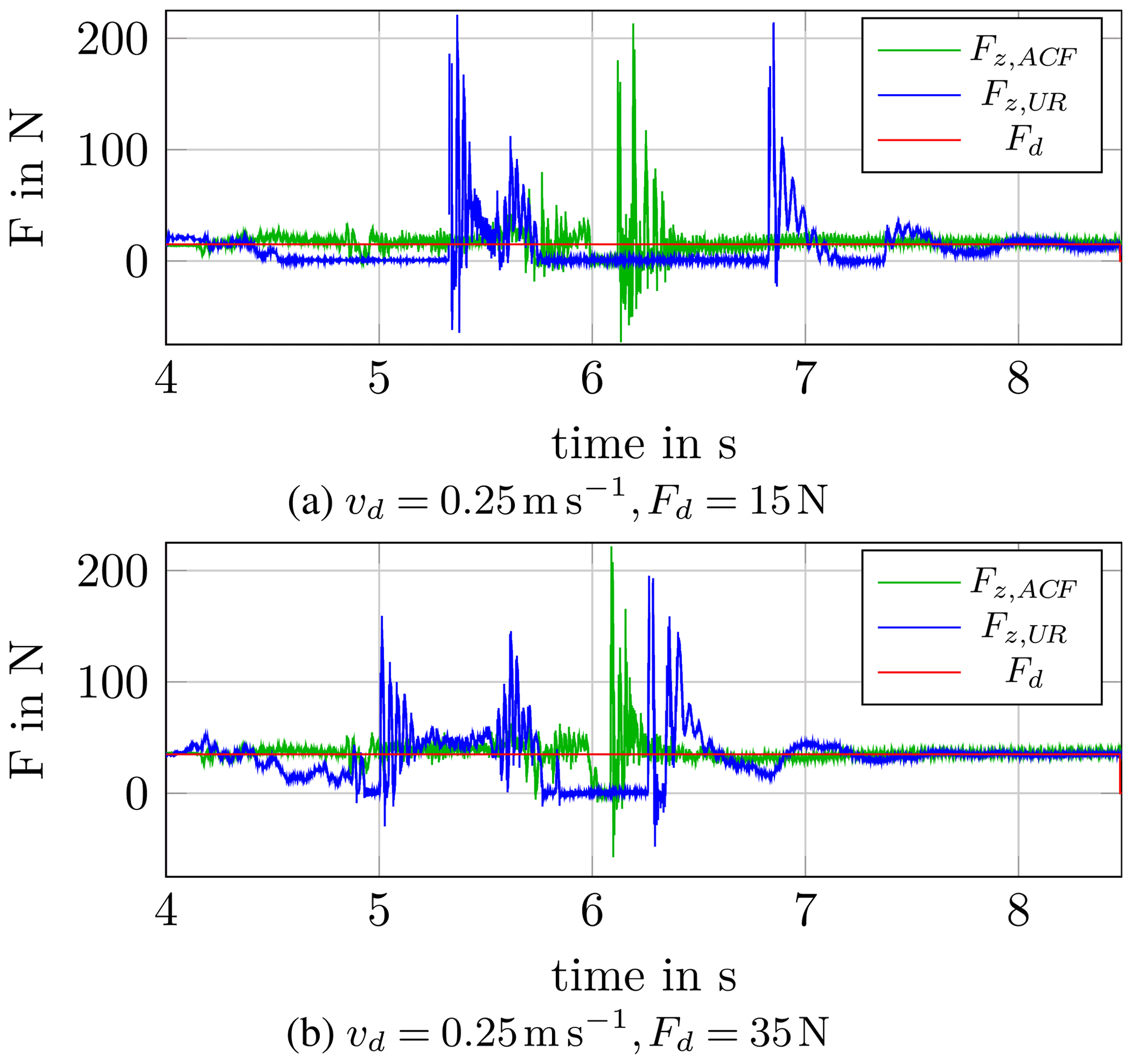
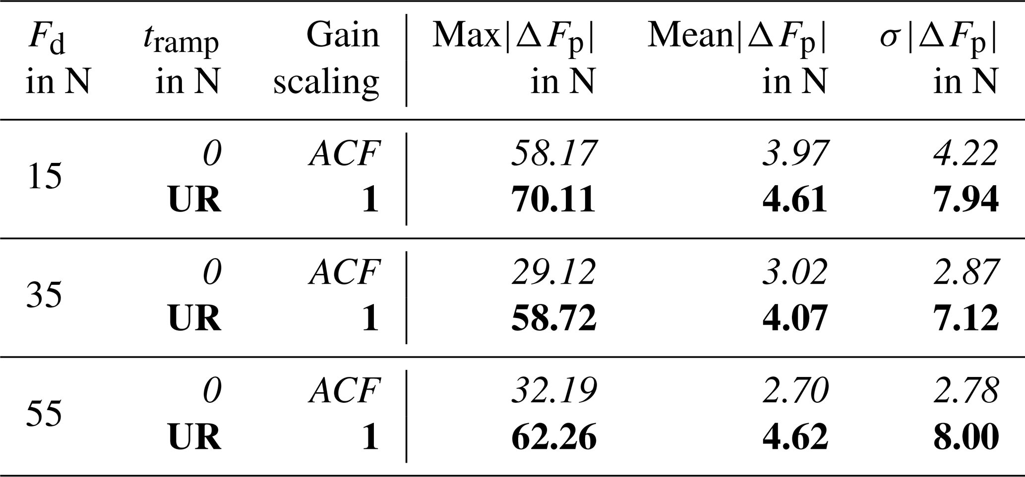
Table 1 summarizes the results for the ramp profile for the average of five test runs with desired velocity vd=0.25 m s−1. The ACF force control leads to much shorter settling times and also to lower force errors for both time domains of interest.
Table 1Assessment of ACF and UR force control, with the ramp profile (vd=0.25 m s−1). Bold font refers to Fz,ACF and italic font to Fz,UR data.

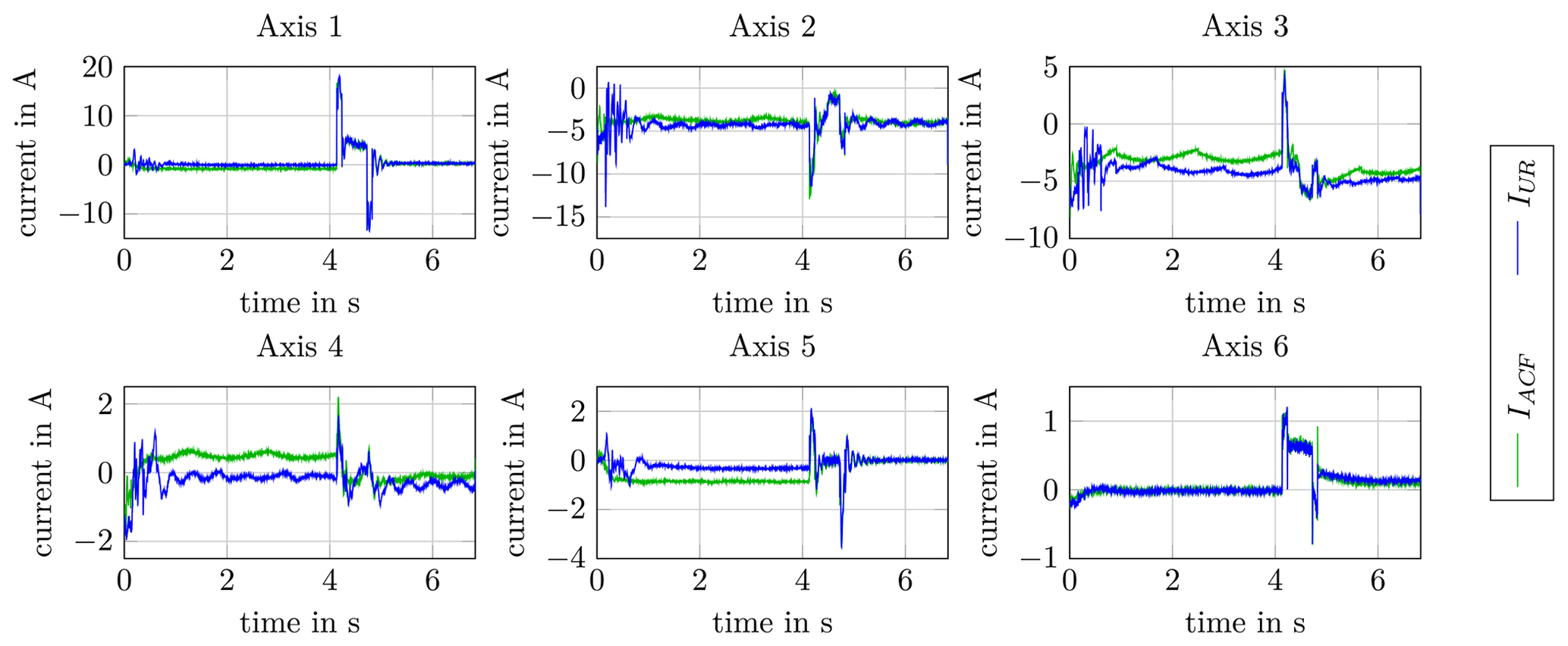
The corresponding UR motor currents for the whole path (first contact, movement, and standstill) for a desired force of Fd=15 N are shown in Appendix A in Fig. A1. Oscillations due to UR force control are also visible in the measured currents.
7.2 Direct sensor contact
This test with a movement directly onto the force/torque sensor that checks the performance of the UR/ACF force control when the desired contact is 100 N. Considering the desired velocities of vd=0.10 m s−1 and vd=0.25 m s−1, the force evolution of Fig. 11 shows a very stable control behaviour of the ACF. This implies a significant advantage of the ACF-K 109/04 over the UR10e. Closely looking at the beginning of Fig. 11, it should be noted that the impact time varies due to the difference between UR position and force control. However, for the assessment the force evolution is synchronized to have the same contact time at t=0.
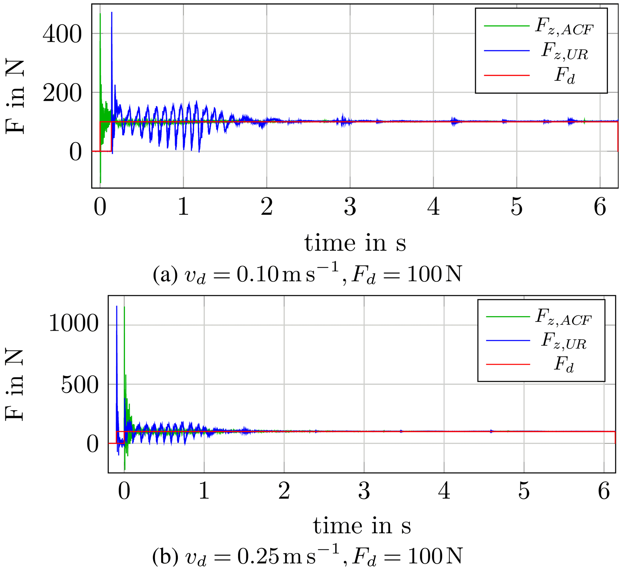
Table 2Assessment of ACF and UR force control, with the direct sensor contact (Fd=100 N).
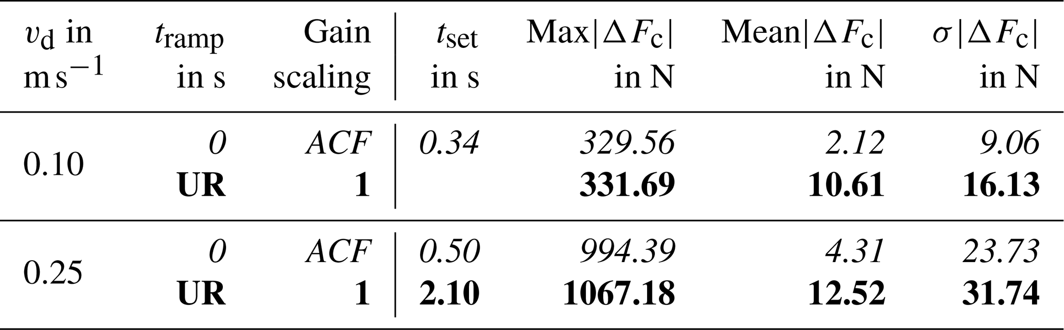
As shown in Table 2, using the average of five test runs, the stable control behaviour of the ACF, even for such a high force, leads to short settling times, especially compared to the UR. This results in much smaller absolute mean errors and standard deviations as well. For vd=0.10 m s−1, the UR force error exceeds the defined error band of ±10 N, and so the oscillation time is impossible to evaluate. The force oscillations due to UR force control are also visible in the measured motor currents of Fig. B1.
7.3 Straight profile
Figure 12 visualizes the forces of the straight profile for a desired TCP velocity of vd=0.90 m s−1 and the desired forces Fd=15 N, Fd=35 N and Fd=55 N. The required horizontal movement for the straight profile simplifies the force control, but the ACF force control is superior. However, during the 2 s long standstill after the movement, the UR force control seems to lead to a marginally lower force offset.
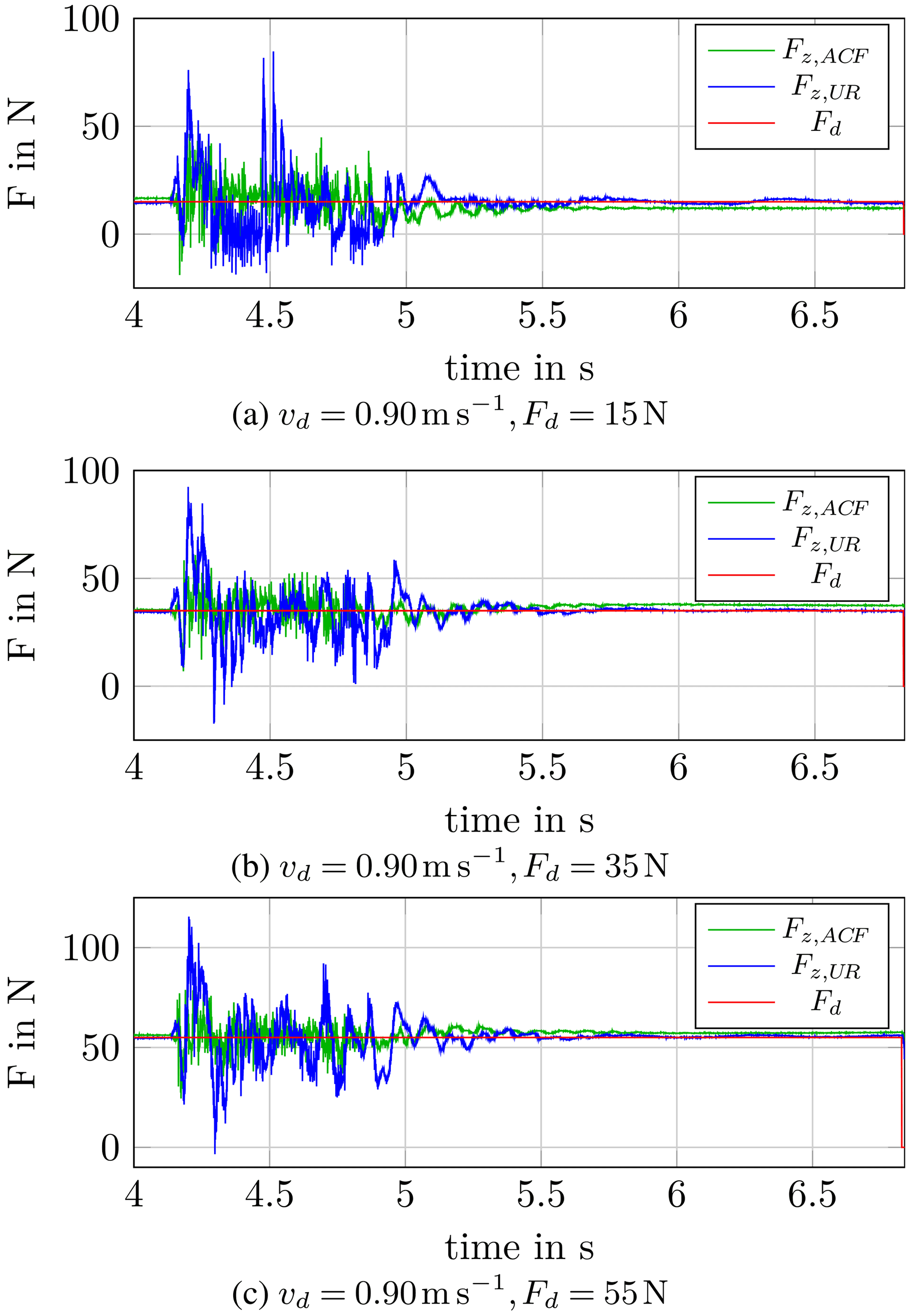
Table 3 summarizes the results of the straight profile, again using the average of five test runs. The ACF achieves better results for the horizontal movement. In particular, the low absolute mean error and corresponding standard deviation reveal the better performance for such high TCP velocity.
Table 3Assessment of ACF and UR force control of movement and standstill, with the straight profile (vd=0.90 m s−1, ).
For completeness, Fig. C1 shows the corresponding UR motor currents for the whole path for a desired force of Fd=55 N.
We proposed realistic test scenarios for the assessment of force control and experimentally evaluated the force control of Universal Robots UR10e and FerRobotics ACF-K 109/04. The results confirm that the UR is well suited to simple, straight line motions with low speed, as it is the intended application for such a collaborative robot. In summary, the ACF force control works well for all tested velocities and forces and guarantees a short transient oscillation. It also shows superior force control behaviour for fast orientation changes. In contrast, the force control of UR10e is suitable to only a limited extent for such fast orientation changes because it temporarily loses contact with the work piece, especially for lower forces. However, the UR force control performance is appropriate for simple, straight line movements and lower velocities. As shown for the test cases, the UR force control performance decreases with increasing TCP velocity. In combination with high forces, and considering the tested parameters, the UR force control even exhibits stability problems. Yet, the UR10e is designed as a collaborative robot (cobot) and not as robot for surface finishing.
The proposed test scenarios for force control evaluation are applicable to general systems. So these test scenarios could serve as a standard force control test, similar to the ISO 9283 test for positioning accuracy evaluation. Future work, involving tests with other robots using different force control implementations or other force compliance devices, is required for a more generalized force control performance benchmarking.


Figure B1Motor currents of the UR drives for the direct sensor contact (vd=0.25 m s−1, Fd=100 N).
Universal Robots (UR script) programmes are provided on the GitHub repository of JKU Linz – Institute of Robotics (2022, https://github.com/JKU-Linz-Institute-of-Robotics/ur10e_force_control_comparison). All other data can be provided by the corresponding author upon request.
Videos from the test scenarios (ramp profile, direct sensor contact, and straight profile) can be provided by the corresponding author upon request.
All measurements and data analysis were performed by SG. SG wrote the draft, while AM and HG reviewed and edited the paper.
At least one of the (co-)authors is a member of the editorial board of Mechanical Sciences. The peer-review process was guided by an independent editor, and the authors also have no other competing interests to declare.
Publisher’s note: Copernicus Publications remains neutral with regard to jurisdictional claims in published maps and institutional affiliations.
This article is part of the special issue “Advances in Service and Industrial Robotics – RAAD2021”. It is a result of the The 30th International Conference on Robotics in Alpe–Adria–Danube Region, RAAD 2021, Futuroscope-Poitiers, France, 21–23 June 2021.
This work has been supported by the LCM – K2 Center for Symbiotic Mechatronics within the framework of the Austrian COMET-K2 programme. For the assessment, the active contact flange ACF-K 109/04 was provided by FerRobotics Compliant Robot Technology GmbH.
This paper was edited by Mohamed Amine Laribi and reviewed by Jozsef Tar and one anonymous referee.
ATI Industrial Automation: ATI Delta SI-660-60, https://www.ati-ia.com/products/ft/ft_models.aspx?id=Delta, last access: 6 December 2021a. a
ATI Industrial Automation: Passive Compliant Force Control Device, https://www.ati-ia.com/products/deburr/ForceControl_Main.aspx, last access: 6 December 2021b. a
B&R Industrial Automation GmbH: B&R X20 AI4632, https://www.br-automation.com/en-gb/downloads/control-and-io-systems/x20-system-coated/analog-io-modules/analog-inputs/x20cai4632/datasheet-x20cai4632/, last access: 11 February 2021a. a
B&R Industrial Automation GmbH: B&R X20 CP3484, https://www.br-automation.com/en-gb/downloads/control-and-io-systems/x20-system/cpus/x20cp3484/datasheet-x20cp3484/, last access: 11 February 2021b. a
Bremer, H.: Elastic Multibody Dynamics – A Direct Ritz Approach, Springer Netherlands, https://doi.org/10.1007/978-1-4020-8680-9, 2008. a
FerRobotics Compliant Robot Technology GmbH: Active Contact Flange, https://www.ferrobotics.com/en/services/products/active-contact-flange/, last access: 6 December 2021a. a, b
FerRobotics Compliant Robot Technology GmbH: Active Contact Flange Kit, https://www.ferrobotics.com/en/services/products/active-contact-flange-kit/, last access: 6 December 2021b. a, b, c
FerRobotics Compliant Robot Technology GmbH: Active Contact Flange – User Manual, 2021c. a
Fritsch, F. N. and Carlson, R. E.: Monotone Piecewise Cubic Interpolation, SIAM J. Numer. Anal., 17, 238–246, 1980. a
Iglesias, I., Sebastián, M., and Ares, J.: Overview of the state of robotic machining: Current situation and future potential, Procedia Engineer., 132, 911–917, 2015. a
JKU Linz – Institute of Robotics: UR10e Force Control Comparison, GitHub [code, data set] https://github.com/JKU-Linz-Institute-of-Robotics/ur10e_force_control_comparison, last access: 13 April 2022 (also available at Zenodo: https://doi.org/10.5281/zenodo.6457906). a, b, c
PushCorp Inc.: Robotic Force Compliance Devices, https://pushcorp.com/productcat/robotic-force-compliance-devices/, last access: 6 December 2021. a, b
Robotiq: Sanding Kit, https://robotiq.com/products/sanding-kit, last access: 6 December 2021. a
Siciliano, B. and Khatib, O.: Springer Handbook of Robotics, Springer, 2nd Edn., 2016. a, b
Siciliano, B. and Villani, L.: Robot Force Control, Springer Science & Business Media, 1999. a, b, c
Universal Robots A/S: Universal Robot UR10e, https://www.universal-robots.com/products/ur10-robot/, last access: 6 December 2021. a, b
Winkler, A. and Suchý, J.: Force Controlled Contour Following on Unknown Objects with an Industrial Robot, in: IEEE International Symposium on Robotic and Sensors Environments (ROSE), IEEE, 208–213, https://doi.org/10.1109/ROSE.2013.6698444, 2013. a
- Abstract
- Introduction
- Desired characteristics
- Control of active and passive compliance
- Test set-up
- Test scenarios
- Assessment criteria
- Results
- Conclusions
- Appendix A: Results for the ramp profile
- Appendix B: Results for the direct sensor contact
- Appendix C: Results for the straight profile
- Code and data availability
- Video supplement
- Author contributions
- Competing interests
- Disclaimer
- Special issue statement
- Acknowledgements
- Review statement
- References