the Creative Commons Attribution 4.0 License.
the Creative Commons Attribution 4.0 License.
 | 26 Aug 2019
Architectural singularities of parallel mechanisms with prismatic joints due to special designs of platform shapes
Shaoping Bai
Singularity is an inherent property of robotic manipulators. A manipulator becomes singular when it gains or losses degrees of freedom at a particular configuration. In this work, a type of singularities caused by special shapes of platforms, either the mobile or the base platform, is addressed. This type of singularities pertains to the architecture singularity, but associated only with special shape designs of base and mobile platforms and spans in the whole workspace, which is referred as shape singularity. The paper provides formulations of shape singularity. The geometry and algebra properties of shape singularity are analyzed. Three examples of shape singularity identification for parallel mechanisms with prismatic joints are included, one for 3-DOF planar mechanisms, the others for 3-DOF and 6-DOF spatial mechanisms. The application of shape singularity in adjustable compliance mechanism design is illustrated.
- Article
(9006 KB) - Full-text XML
- BibTeX
- EndNote


Singularity analysis is essential for robotic manipulators, particularly for parallel kinematics machines (PKMs). Up to date, singularity analysis has been extensively addressed in literature. A classic article on singularity analysis was published by Gosselin and Angeles (1990), which defines three different types of singularities, namely, the input singularity (Type I or forward singularity), output singularity (Type II or inverse singularity), the combined singularity (Type III singularity). These three types of singularities have been studied for numerous types of robots. Husty and Zsombor-Murray (1994) reported a special type of singular Stewart–Gough platform, in which the six leg axes remain in a specific linear complex, congruence or hyperbolical ruled surface under the singular configuration, which they called constraint singularity. Zlatanov et al. (2002) studied the constraint singularity for a PKM with less than six DOFs, where both the mechanism as a whole and the mobile platform (MP) have at least one increased DOF. Liu et al. (2003) reported the configuration singularity, which was identified through the differential forms associated with the constraint functions. Regarding the analysis approaches, Park and Kim (1999) proposed a coordinate-invariant differential geometric method for analysis of kinematic singularities for closed kinematic chains containing both active and passive joints. Merlet (1989) adopted a method based on Grassmann line geometry for the singularity analysis of PKMs. Bonev et al. (2003) applied screw theory in the singularity analysis of 3-DOF planar PKMs. Other researches on singularity analysis can be found in the works of Amine et al. (2012); Liu et al. (2012); Zarkandi (2011); Fang et al. (2012); Gan et al. (2013); Wolf and Glozman (2011); Alici and Shirinzadeh (2004); Wang and Gosselin (1997); Romdhane et al. (2002); Bandyopadhyay and Ghosal (2004); Li et al. (2003), and Kim and Chung (1999).
Most singularity analyses up to date were conducted for configuration dependent singularity. As reported by Ma and Angeles (1991b), singularities can also be classified into three different categories, namely, architecture, configuration and formulation singularities. Among them, architecture singularity is a type of singularity which is caused by a special architecture of a manipulator and it exists for all configurations inside the whole or a part of the workspace. Related works can be found in the works of Borrás et al. (2011) and Karger (2008), where architecture singularity was studied for cases with collinear points in the MP or in the base.
The singularity analyzed in this work pertains to the architecture singularity. Its analysis is focused on the shapes of the MP and the base platform. The objective is to explore the influence of the shape design of platforms on the singularity. It is noticed that most manipulators studied are assumed of having a fixed shape of the MP and base platforms, while cases with different shapes of the platforms are rarely considered. It is thus desirable to study what will happen with a variety of shapes of MP and base platforms. In a recent work by Wu et al. (2017), it was found numerically that a manipulator becomes singular due to some special shapes of base and mobile platforms. To be concise, we refer the singularity due to special shapes of the platforms as shape singularity. In that work, we study generally the shape singularity and identify the singularities for the 3-PPR, 3-PPS and 3-PPPS mechanisms.
Another objective of this work is to explore utilizing their singularities in novel mechanism designs. While most singularity analyses were carried out with purpose to identify the singular configurations and to eliminate singularity from the perspective of manipulator design and control, it would be of great significance if a singularity analysis could inspire novel mechanism designs. As reported recently by Rubbert et al. (2014), singularities can also be used to enhance compliance performance of mechanisms.
In this paper, we define and formulate the shape singularity, which is determined by parameters describing the shapes of the mobile and base platforms. Properties of shape singularity are analyzed. Examples of shape singularity analysis for three PKMs are presented, along with an example of adjustable compliance mechanism based on shape singularity.
The paper is organized as follows. Section 2 provides the definition of shape singularity, with equations for the shape singularity formulated. Section 3 presents the identification of shape singularity in planar 3-PPR mechanisms. The shape singularity identification is extended to spatial 3-PPS and 3-PPPS PKMs in Sects. 4 and 5. The application of shape singularity is presented in Sect. 6. The work is discussed and concluded in Sect. 7.
We start with a general description of PKMs. A PKM is modeled as a set of serial kinematic chains connected in parallel to two rigid bodies, namely, the base platform and the MP. The manipulator's motion is described through joint variables , and MP motion variables , where n is the number of DOFs of the manipulator.
The manipulator's constraint equation is generally expressed as
The velocity equation is obtained by differentiating Eq. (1)
with
Then the Jacobian matrix of the manipulator can be expressed as
With the above equations, extensive studies have been done to investigate the influence of link dimensions and motion variables.
Our purpose is to look into the influence of platform shapes. In this light, we include shape parameters in the formulation.
The velocity equation remains unchanged in its form, but J is a function of both motion variables x and shape parameters s, namely,
As mentioned in the works of Ma and Angeles (1991b), Borrás et al. (2011), and Karger (2008), both size/dimension parameters and shape parameters can lead to architecture singularity, where the latter one is specially referred to as shape singularity. More specifically, shape singularity is a singularity that is uniquely determined by the shape of platforms of a PKM. The platform shape of the PKM under shape singularity is called singular platform shape, or, singular shape in short.
With regard to the shape singularity, the following characteristics are noted:
-
Remark 1: The unique determination of the shape singularity means that the singularity is only depended on shape parameters, not motion variables, or in other words, the shape singularity is configuration independent.
-
Remark 2: According to Remark 1, a PKM with shape singularity is singular in all configurations. This is in line with the architecture singularity.
-
Remark 3: For shape singularity, the shape is unique, while the associated design configurations are not. This means that infinite singular PKMs with one or more shape parameters taking different values exist for the same singular shape.
For any given set of shape parameters, Remark 2 implies that
In other words, f is a constant function, thus its derivatives w.r.t. motion variable should vanish
where n is the number of MP motion variables.
Equations (7) and (8) are the system of shape singularity equations. With proper algebraic manipulation, a function in terms of shape parameters that leads to shape singularity can be obtained. The function will normally be obtained as an implicit function as
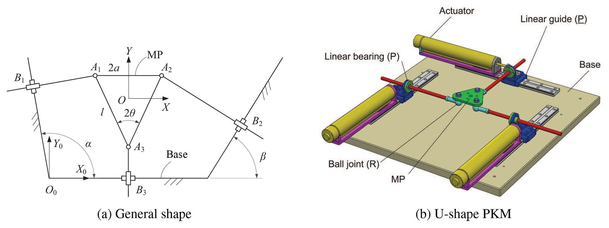
We include three examples to demonstrate the identification and analysis of shape singularity. The first example is a planar 3-PPR PKM, as shown in Fig. 1a. This model is a generalized 3-PPR PKM, where the base and MP are parameterized. Special cases are the Δ- and U-shape 3-PPR PKMs (Binau et al., 2010; Wu and Bai, 2012), the U-shape one being depicted in Fig. 1b.
The MP is modeled as an isosceles triangle with side length l and vertex angle 2θ. The base platform is defined geometrically with adjacent angles α, β for the two linear guides.
The global frame {O0} is attached to the base with its origin located at a corner of the base, where X0-axis is parallel to the bottom line of the base. Local frame {O} is attached to the MP with its origin located at its geometric center. Rotation angle ϕ of the MP is measured counter-clockwise from X0-axis to X-axis.
Referring to Wu et al. (2017), the Jacobian matrix of the PKM is readily obtained
where a=lsθ and . Hence 2a and 3h define the bottom side length and the height of the MP. Moreover, s and c stand for sine and cosine, respectively.
The determinant of the Jacobian matrix in Eq. (10) is expressed as
which is a function of motion variable ϕ and shape parameters α,β and θ. We take the derivative of f with respect to motion variable ϕ and let it equal to zero
Equation (11) can be expressed as a linear function of cϕ and sϕ,
with
Similarly, Eq. (12) can be expressed as
with
The system of the two equations can now be written as
with
The determinant of M has to be zero, so we have
which is
This equation stands for the manifold of all shape parameters that leads to shape singularity. Figure 2a and b show the 3-D surface of function g, plotted for two given values of θ.

It can be seen from the plots of g that there are some points where g becomes zero, which are the points of shape singularity. Equation (22) was solved analytically by virtue of computer algebra, which yields three singular shapes
The corresponding manipulators are shown in Fig. 3a–c. For the first singular shape, as shown in Fig. 3a, the lines of translation of the active prismatic joints are parallel, and perpendicular to the lines of translation of the three passive prismatic joints. The MP can still move along the direction of the passive prismatic joints even though all the three active joints are locked.
For the second singular shape depicted in Fig. 3b, the MP can perform a small rotation about an instantaneous center of rotation (G1), even all the actuators are locked. For the third singular shape, as shown in Fig. 3c, a small rotation of the MP about an instantaneous center of rotation (G2) is feasible, even with all the actuators locked. The instantaneous rotation of the MP in both cases can also be easily interpreted by Arnold–Kennedy theorem (Mohammadi, 2005).
In the aforementioned three singular shapes, there are infinitive many designs associated with each shape. Take the second shape as example, the manipulator is singular while can take any values satisfying Eq. (23b), but the shapes of the base and MP remain the same. In other words, it is only the shape that determines this type of singularity.
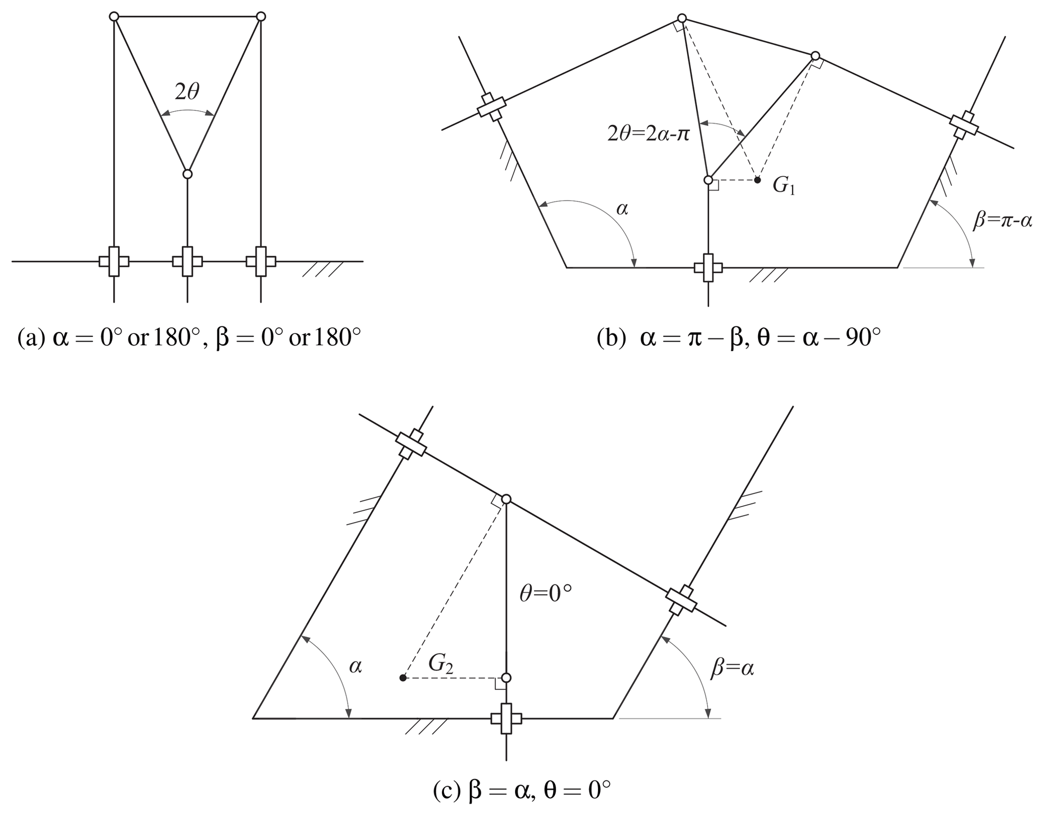
Figure 3Singular shapes of the 3-PKM. The shape of the base platform in (a) can be viewed as a straight line, while the base platforms in (b) and (c) are isosceles trapezoid and parallelogram, respectively, if we virtually close the opening by drawing a line parallel to the bottom line.
In the above formulation, if we include l as a shape variable too, a trivial solution of l=0 will be obtained, which means the MP becomes geometrically a point.
The formulation of Eq. (22) is derived to display the manifold and to obtain the solutions of shape singularity. If our interest is only the shape singularity solution, an alternative formulation is readily obtained by letting all coefficients equal to zero, namely,
The system of coefficient equations yields the same results as Eq. (23).
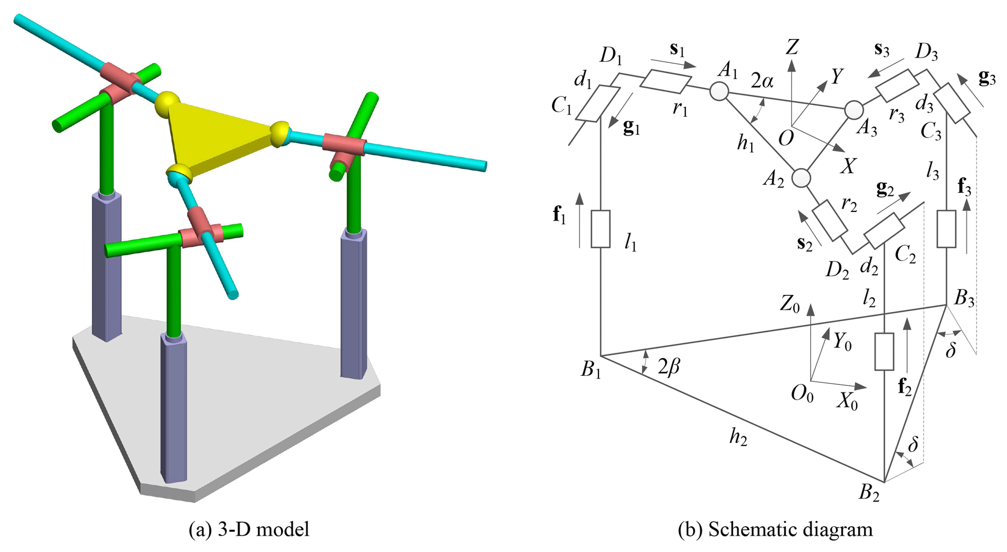
The second example is about a spatial PKM, namely, a 3-PPS PKM. The model of general 3-PPS PKM is shown in Fig. 4a and b. A special case of 3-PPS PKM discussed in the work of Bonev (2008) is depicted in Fig. 4c.
The shape of MP is defined as an isosceles triangle with side length h1 and vertex angle 2α, the feasible range of the angle being defined as ∘. The base platform is defined in a similar way with side length h2 and vertex angle 2β (∘). The axes of the passive prismatic joints are perpendicular to the axes of the actuated prismatic joints, while the orientation of axes of the actuated prismatic joints is described by the pan angle δ (∘) and tilt angle γ (∘).

4.1 Kinematics of the 3-PPS PKM
We formulate first the kinematics model of mechanism by including shape parameters. As shown in Fig. 4b, the global frame {O0} is attached to the base with its origin located at the centroid of the base, where Y0-axis is pointed along the direction of B2B3, Z0 is perpendicular to the base. Local frame {O} is attached to the MP and defined in a similar way.
For general 3-PPS PKM (), let describe the pose of the MP with respect to the global frame. The position vector of point Ai in general 3-PPS PKM is obtained by
where is the position vector of point Ai in the local frame, R=Rz(ϕ)Ry(θ)Rx(ψ) is the rotation matrix and is the position vector of point O in the global frame.
Let , be the position vectors of points Ai and Bi in the global frame. Projection of Ai in the base plane satisfies following equations
The position vector of point Bi is
By virtue of Eqs. (25)–(27c), we obtain,
Substituting Eqs. (29a)–(29c) into Eq. (25), we can determine the position of point Ai expressed by z, ψ and θ.
The position vector of point Ai can also be expressed in a form as
where unit vectors fi for the axes of the active prismatic joints are
where i is the unit vector parallel to X0-axis, while the unit vectors gi for the axes of the passive prismatic joints are
Combining Eqs. (25) and (30) yields solutions to the inverse position problem,
Differentiating both sides of Eqs. (33a)–(33c) with respect to time, we obtain
where is the velocity vector of the active prismatic joints, is the velocity of the MP, and J2 is the Jacobian matrix.
Two cases need special attention:
(a) δ=0∘, the actuating input of each actuator can be expressed as
its Jacobian matrix then takes the form of
The determinant of the Jacobian matrix of Eq. (37) is found as zero.
(b) δ=90∘, the actuating input of each actuator can be expressed as
By differentiating Eqs. (38)–(40), the Jacobian matrix can be obtained.
4.2 Singular shapes for the 3-PPS PKM
The first equation to determine the shape singularity is defined form zero determinant of the Jacobian matrix
Equation (8) implies three more equations for 3-PPS PKM,
where xi are the three motion variables z,ψ and θ. We further define
A solution satisfying Eq. (43) will naturally satisfy Eqs. (41) and (42). For the 3-PPS PKM, four shape parameters are considered. We need to identify shape parameters to satisfy Eq. (43). Preliminary examination finds that β has less influence on shape singularity unless β=0 which yields a trivial PKM. So we mainly analyze the shape singularity for three shape parameters, α,γ and δ.
4.2.1 Special case of δ=0∘
We first look at a special case of δ=0∘. In this case, the Jacobian matirx is found always singular. The determinant and its derivatives with respect to the configuration variables vanish. The 3-PPS PKMs with δ=0 are of shape singularity.
4.2.2 Other cases
In other cases of δ≠0∘, function g is not generally vanish. We plot the variations of function g with respect to the three shape parameters of interest, as shown in Fig. 5. In each plot, one of the three parameters are fixed.
All plots in Fig. 5 are generated for an arbitrary configuration. From the plots, we can found that g becomes zero for the following situations: (1) γ=0∘ or 180∘, when the three active prismatic joints are coplanar with the base platform; (2) α=0∘ or α=90∘, when the three vertexes are collinear. Plots with a few other configurations are generated too. Similar plots are obtained, in which g becomes zero for the same situations.
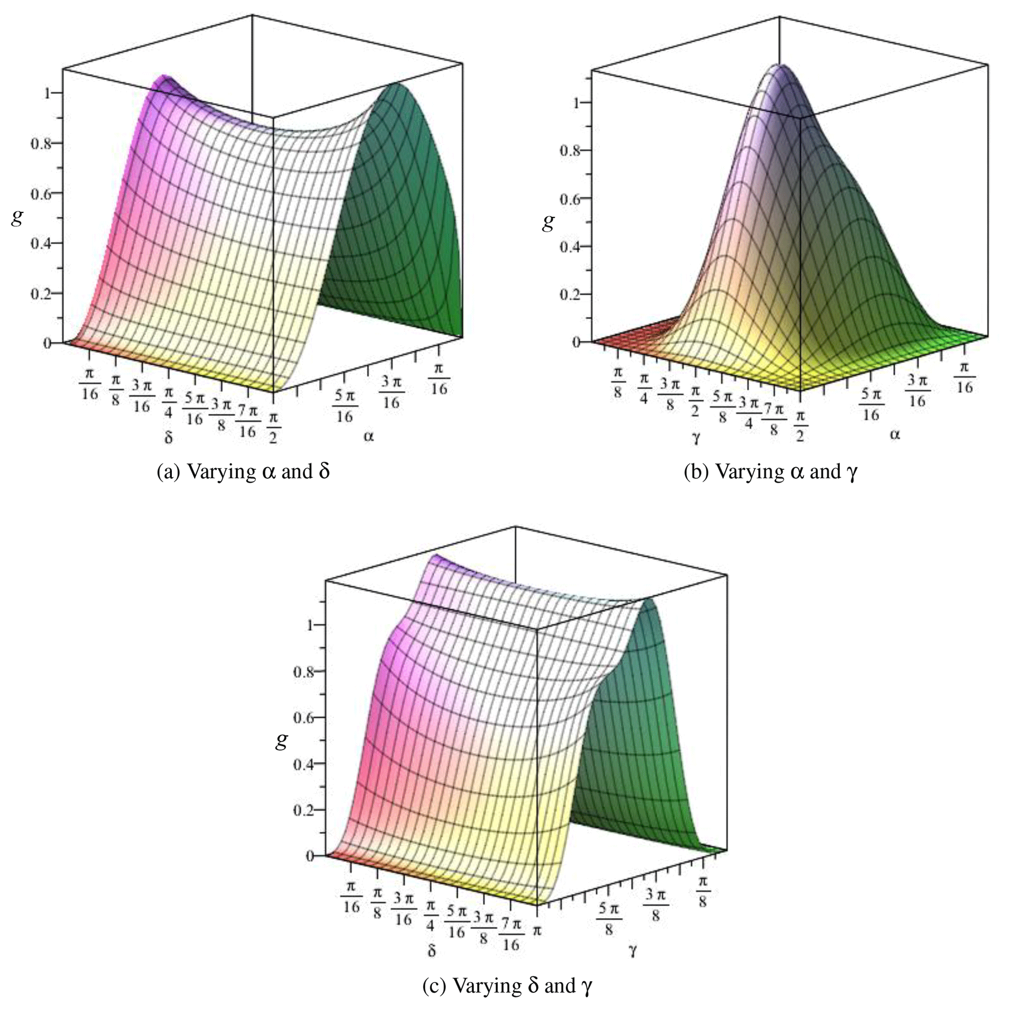
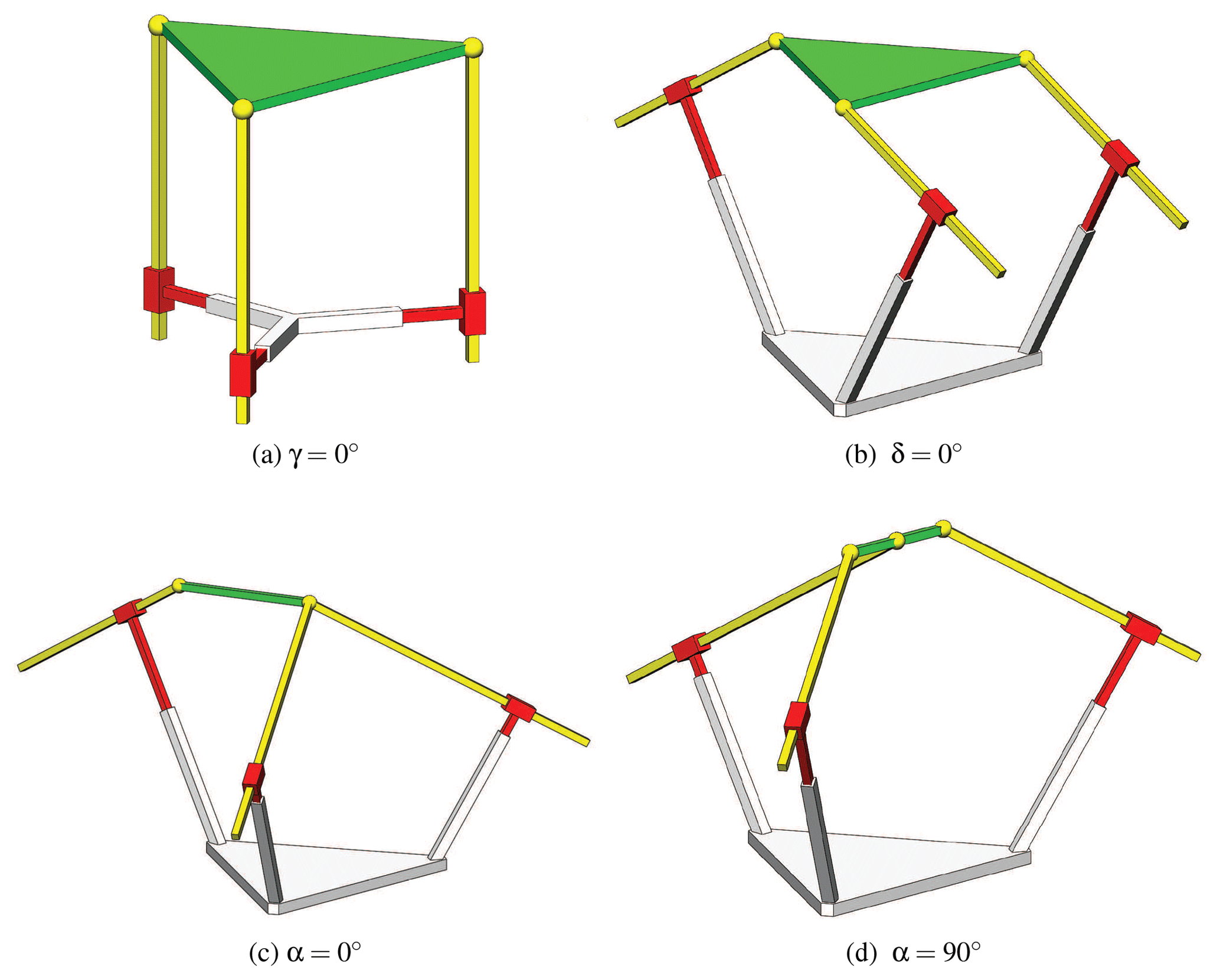
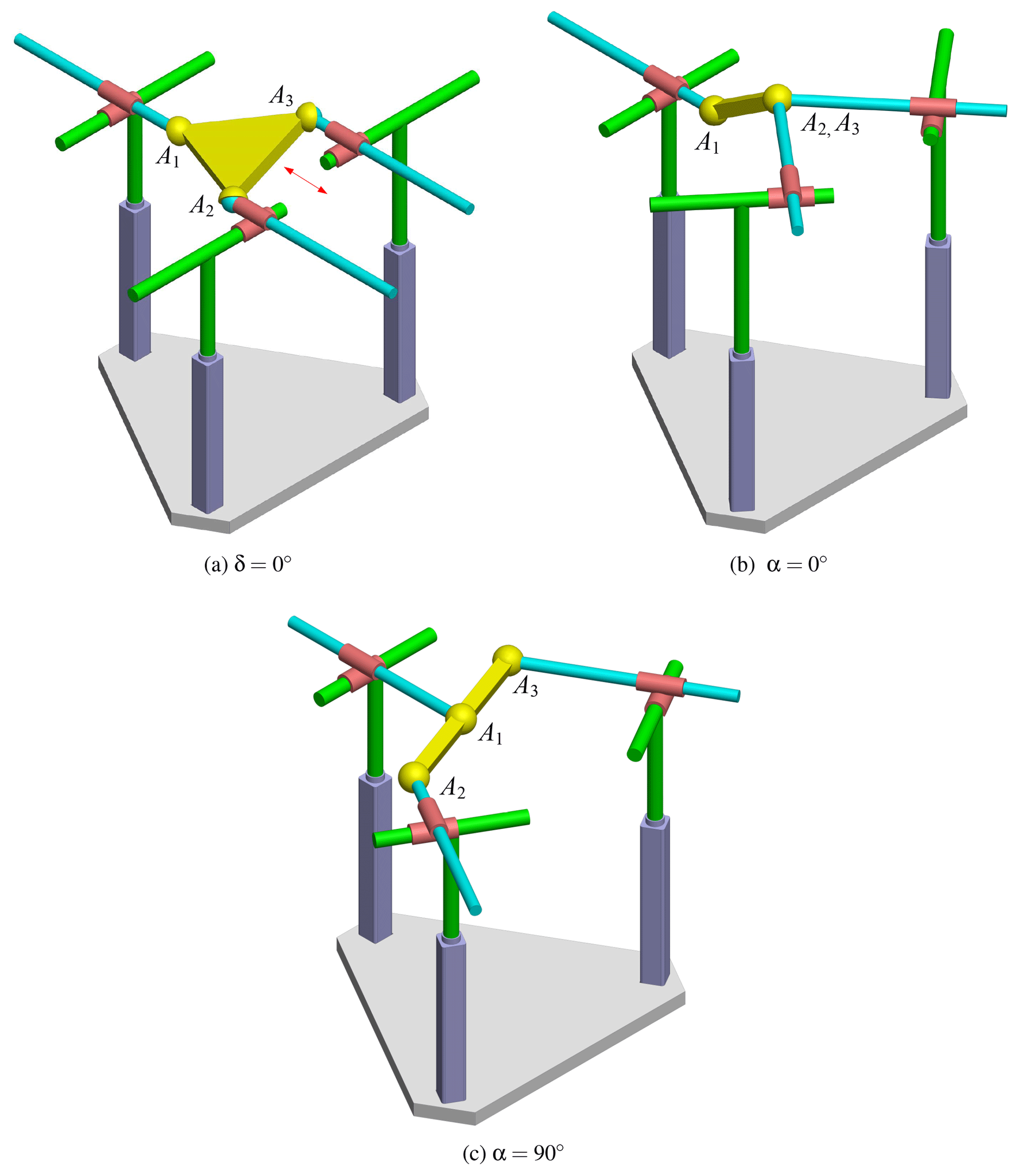
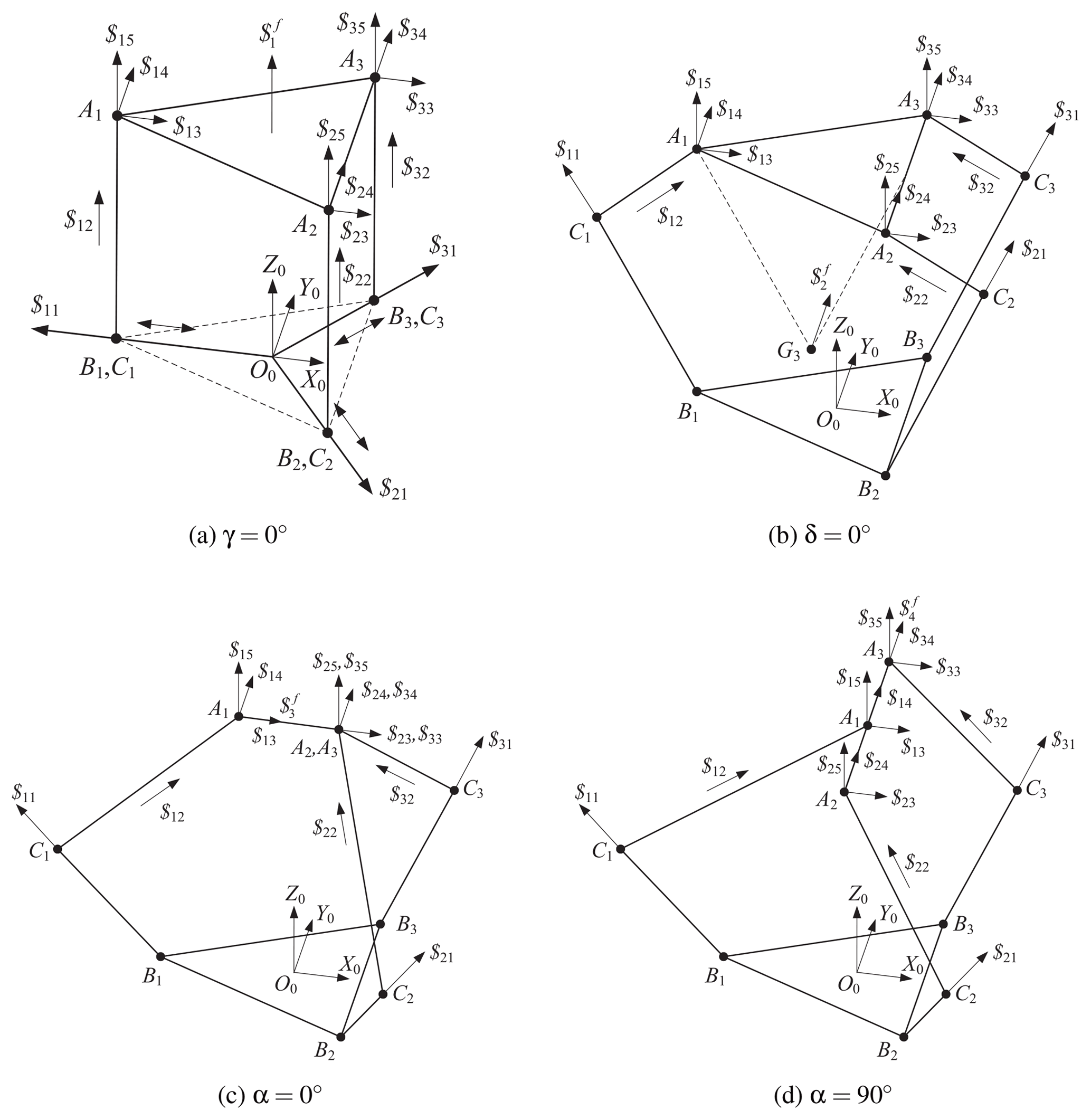
In summary, both functions f and are equal to 0 in following four situations: (1) δ=0∘; (2) γ=0∘ or 180∘; (3) α=0∘ and (4) α=90∘. In all four situations, the PKMs are of shape singularity. The PKMs with these singular shapes are depicted in Figs. 6a–d.
The singular shapes identified by combination of analytical formulation and graphics method can be further justified with other methods, for example, screw theory (Wu et al., 2017). Appendix provides verification of these shape singularity by means of screw theory.
We include one more example of shape singularity analysis for 6-DOF PKMs. Here, a 3-PPPS PKM with six DOFs is taken into consideration, as depicted in Fig. 7a. The three limbs are identical, which consists of two active prismatic joints (the first two joints), one passive prismatic joint and one passive spherical joint. Moreover, the axes of the three prismatic joints in each limb form an orthogonal reference frame.
Both the local frame, global frame and shape parameters chosen for the 3-PPPS PKM are similar with the 3-PPS one, as shown in Fig. 7b, so these details will not be described in this section. On the other side, a brief introduction of the inverse kinematics and Jacobian matrix are presented below.
Here, the position vector of point Ai in the global frame can be expressed as
where unit vector fi for the axis of the first active prismatic joint in each limb is
Unit vector gi for the axis of the second active prismatic joint in each limb can be obtained as
Moreover, unit vector si for the axis of the passive prismatic joint is
Multiplying both sides of Eq. (44) with vector fi and gi respectively, we can obtain the solutions to the inverse position problem.
Differentiating both sides of the Eqs. (48) and (49) with respect to time, the Jacobian matrix can be expressed as
with
With the obtained Jacobian matrix and the same method mentioned in the previous sections, analysis of shape singularity of the 3-PPPS PKM is conducted. It is found that, with the shape parameters considered, singular shapes exist in any of the three cases, (1) δ=0∘, (2) α=0∘, (3) α=90∘, as shown in Fig. 8. For δ=0∘, when the three limbs are parallel to each other, the MP can still move along the direction of the passive prismatic joints with all active joints locked. With respect to α=0∘ or α=90∘, the MP can still rotate about the axis of A1A2 even though all the six actuators are locked.
The shape singularity can have some practical implications in PKM design, where the singularity is used to enhance the PKM's performance, namely, the compliance, as the example reported in the work of Rubbert et al. (2014). In robotics and automation applications, compliance is needed for certain operations which compliant interaction between the robot and the environment. Two usually used compliance are passive and active compliance (Schutter and Brussel, 1988). For passive compliance, it contains an elastic element, e.g. a spring which can store energy. On the other hand, active compliance is based on the control of stiff actuators to mimic the behavior of the spring (Albu-Schäffer, 2008).
It is known that a mechanism exhibits a large compliance in near-singularity configurations. With the shape singularity, it is possible to adjust the compliance by means of shape adjustment, as we illustrate presently with the 3-PPR PKM.
The stiffness matrix (Gosselin, 1990; Wu et al., 2010) of the 3-PPR PKM can be expressed as
where Kp is a matrix describing the stiffness of the platform mounted with elastic elements. For simplicity, . The deflection of the mobile platform is thus
where is the PKM's compliance matrix.
Note that, the first two columns of the Jacobian matrix as mentioned in Eq. (10) are without units while the third has units of length. A simple method for rendering these units homogeneous is to divide the elements of the third column by a characteristic length (Ma and Angeles, 1991a; Arsenault and Boudreau, 2004). For the considered 3-PPR PKM, side length l is chosen as the characteristic length.
To determine the limit value of the deformation, a Lagrange function is defined as
where λi is the Lagrangian multiplier.
The stationary value of L should satisfy following equations
which yields
Obviously, λi is the eigenvalue of . Then, we can obtain following equation
This shows that the maximum or minimum eigenvalue λi of is the limit value of . Let and , the maximum and minimum deformations can be expressed as
The stiffness matrix of the 3-PPR PKM, with θ=30∘ and shape parameter included, is expressed as
with
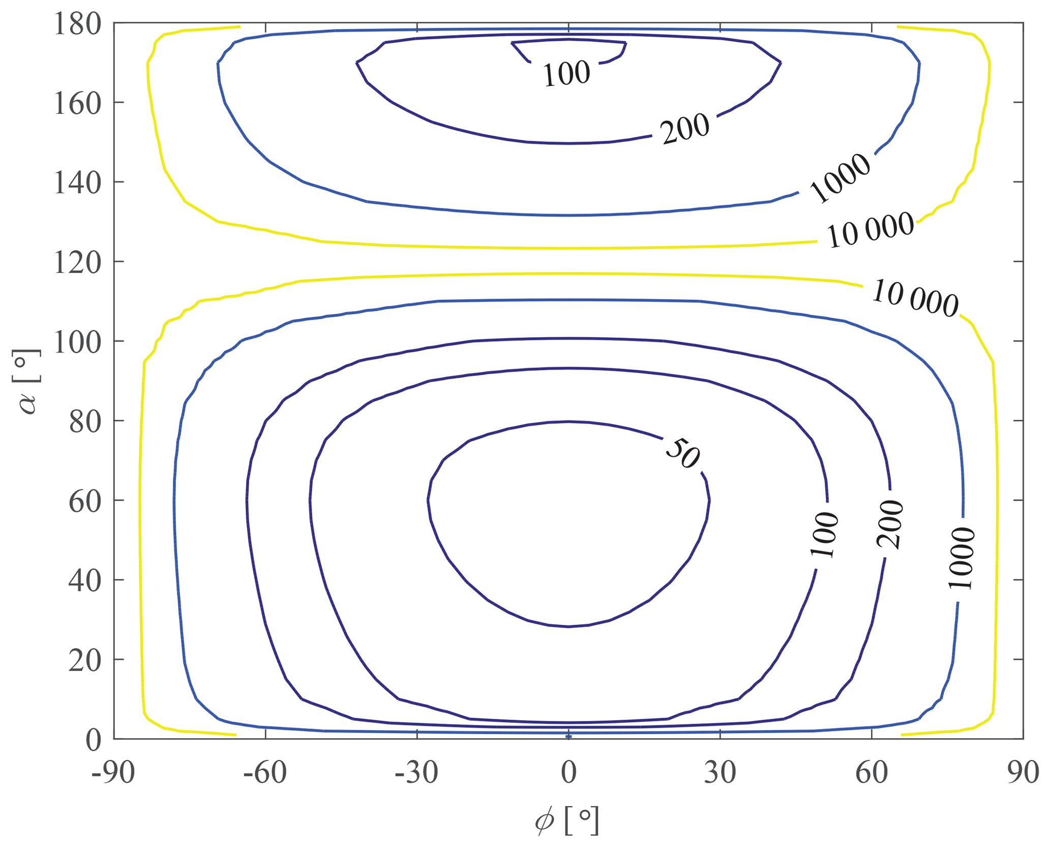
According to Eq. (58), the distribution of maximum deformation Smax is obtained and depicted in Fig. 9. It is found that the distribution of compliance is symmetrical about ϕ=0∘, and the compliance is very high near ϕ=0∘. On the other hand, the compliance changes significantly when it approaches to singular configurations (∘). Moreover, singular shapes (α=0∘, 120∘ and 180∘) also possess great compliance performance.
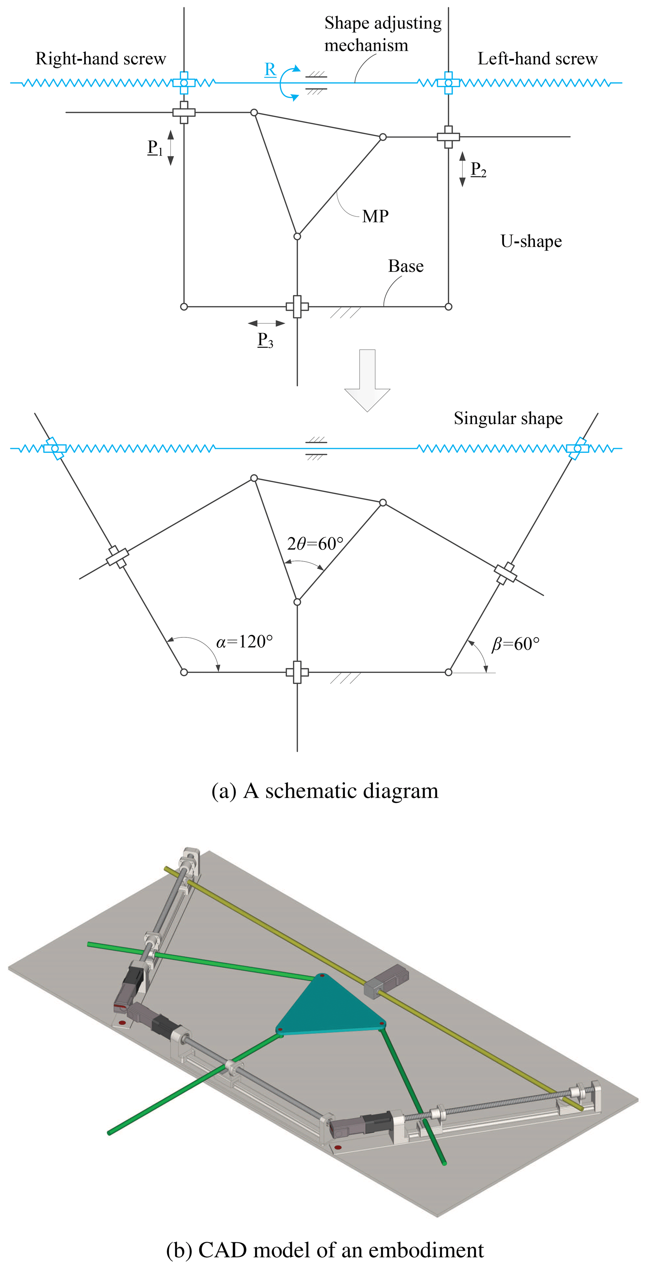
Figure 10 shows a schematic of compliance adjustable PKM and an embodiment. In the mechanism, P1, P2 and P3 are actuators of the 3-PPR PKM, R is the actuator of the shape adjusting mechanism which used to change the shape of the base. By controlling the movement of R, the shape of the base platform can be adjusted, and thus compliance can be changed accordingly.
The objectives of this work are two folds. One objective is to investigate the influence of platform shapes on the singularity. The other is to explore the application of platform-shape related singularity in the novel mechanism design. In this work, shape singularity analysis is formulated and analyzed, with respect to the shapes of MP and base platform. Shape singularity identification was conducted for both planar and spatial mechanisms. New and non-trivial shape singularities are revealed. In the literature, the shape singularity are found for either the mobile platform and the base platform having similar shapes, or some points in the MP or the base are collinear. In this work, shape singularities with a variety of platform shapes are identified, which is a contribution of this work.
The identification of PKMs with shape singularity has some practical implications in robotic mechanism design. A PKM of shape singularity could find potential applications in assembly, as it can provide a high compliance due to the presence of instantaneous center of rotation, thus form a remote center of compliance (Kieffer and Lenarcic, 1994). New devices can thus be envisaged for this type of applications.
In this work, we only analyze shape singularity of three types of PKMs, for which the platform shapes are described by selected parameters. Needless to say, shape singularity of other PKMs with duly selected shape parameters and possible new compliant PKMs will be topics of future research.
All the data used in this article can be made available upon reasonable request. Please contact the corresponding author (wuxy@cqut.edu.cn).

Figure (A1) shows all twist screws of the manipulator. Taking the first limb for an example, the twist screws can be written as
where j and k represent the unit vectors of Y0- and Z0-axis.
When the actuators are locked, the wrench screws of the first limb are
where .
In a similar way, the wrench screws of another two limbs can be obtained
The system of wrench screws of the considered manipulator with all actuators locked can be expressed as
which can be written in matrix form as
If the manipulator is fully constrained and free of shape singularity, the rank of Q will be equal to 6. Otherwise, a lower rank Q implies a unconstrained motion feasible and the PKM is shape singular for the given shape parameters.
We can now check the four singular shapes as presented in Sect. 4. We redraw the four cases with screws displayed, as shown in Fig. A2a–d.
We take Case 2 (δ=0∘) shown in Fig. A2b as an example. The wrench screws can be expressed as
The reciprocal screw of the wrench screws is found as
This means there is a unconstrained instantaneous motion of MP that rotates about an axis, the instantaneous screw axis, which is parallel to Y0-axis and passing through point G3. The position vector of point G3 is
Other cases, Case 1, 3 and 4, can be shown similarly with screw theory that they are shape singular, which support the numerical identification results.
XW conducted theoretical calculation and example studies and wrote the manuscript under the guidance of SB. SB verified the established model and supervised the whole work.
The authors declare that they have no conflict of interest.
This paper was edited by Chin-Hsing Kuo and reviewed by Miguel Díaz-Rodríguez and one anonymous referee.
Albu-Schäffer, A.: Soft robotics: From torque feedback controlled lightweight robots to intrinsically compliant systems, IEEE Robot. Autom. Mag., 15, 20–30, 2008. a
Alici, G. and Shirinzadeh, B.: Topology optimisation and singularity analysis of a 3-SPS parallel manipulator with a passive constraining spherical joint, Mech. Mach. Theory, 39, 215–235, 2004. a
Amine, S., Masouleh, M., Caro, S., Wenger, P., and Gosselin, C.: Singularity conditions of 3T1R parallel manipulators with identical limb structures, J. Mech. Robot., 4, 011011, https://doi.org/10.1115/1.4005336, 2012. a
Arsenault, M. and Boudreau, R.: The synthesis of three-degree-of-freedom planar parallel mechanisms with revolute joints (3-RRR) for an optimal singularity-free workspace, J. Field Robot., 21, 259–274, 2004. a
Bandyopadhyay, S. and Ghosal, A.: Analysis of configuration space singularities of closed-loop mechanisms and parallel manipulators, Mech. and Mach. Theory, 39, 519–544, 2004. a
Binau, N., Caro, S., Bai, S., and Wenger, P.: Comparison of 3-PPR parallel planar manipulators based on their sensitivity to joint clearances, IEEE Int. C. Int. Robot., 18–22 October 2010, Taipei, Taiwan, 2778–2783, 2010. a
Bonev, I.: Direct kinematics of zero-torsion parallel mechanisms, IEEE Int. Conf. Robot., 19–23 May 2008, Pasadena, CA, USA, 3851–3856, 2008. a
Bonev, I., Zlatanov, D., and Gosselin, C.: Singularity analysis of 3-DOF planar parallel mechanisms via screw theory, J. Mech. Design, 125, 573–581, 2003. a
Borrás, J., Thomas, F., and Torras C.: Architectural singularities of a class of pentapods, Mech. Mach. Theory, 46, 1107–1120, 2011. a, b
Fang, H., Fang, Y., and Zhang, K.: Reciprocal screw theory based singularity analysis of a novel 3-DOF parallel manipulator, Chin. J. Mech. Eng., 25, 647–653, 2012. a
Gan, D., Dai, J. , Dias, J., and Seneviratne, L.: Unified kinematics and singularity analysis of a metamorphic parallel mechanism with bifurcated motion, ASME. J. Mechanisms Robotics, 5, 031004–031004-11, 2013. a
Gosselin, C.: Stiffness mapping for parallel manipulators, IEEE T. Robotic. Autom., 6, 377–382, 1990. a
Gosselin, C. and Angeles, J.: Singularity analysis of closed-loop kinematic chains, IEEE T. Robotic. Autom., 6, 281–290, 1990. a
Husty, M. and Zsombor-Murray, P.: A special type of singular Stewart–Gough platform, Advances in Robot Kinematics and Computational Geometry, Springer Netherlands, 449–458, 1994. a
Karger, A.: Architecturally singular non-planar parallel manipulators, Mech. Mach.Theory, 43, 335–346, 2008. a, b
Kieffer, J. and Lenarcic, J.: On the exploitation of mechanical advantage near robot singularities, Informatica, 18, 315–323, 1994. a
Kim, D. and Chung, W.: Analytic singularity equation and analysis of six-DOF parallel manipulators using local structurization method, IEEE T. Robotic. Autom., 15, 612–622, 1999. a
Li, Y., Huang, Z., and Chen, L.: Singular loci analysis of 3/6-Stewart manipulator by singularity-equivalent mechanism, IEEE Int. Conf. Robot., 14–19 September 2003, Taipei, Taiwan, 1881–1886, 2003. a
Liu, G., Lou, Y., and Li, Z.: Singularities of parallel manipulators: A geometric treatment, IEEE T. Robotic. Autom., 19, 579–594, 2003. a
Liu, X., Wu, C., and Wang, J.: A new approach for singularity analysis and closeness measurement to singularities of parallel manipulators, J. Mech. Robot., 4, 041001, https://doi.org/10.1115/1.4007004, 2012. a
Ma, O. and Angeles, J.: Optimum architecture design of platform manipulators, IEEE Int. Conf. Robot., 19–22 June 1991, Pisa, Italy, 1130–1135, 1991a. a
Ma, O. and Angeles, J.: Architecture singularities of platform manipulators, IEEE Int. Conf. Robot., 9–11 April 1991, Sacramento, CA, USA, 1542–1547, 1991b. a, b
Merlet, J.: Singular configurations of parallel manipulators and Grassmann geometry, Int. J. Robot. Res., 8, 45–56, 1989. a
Mohammadi, H.: Instantaneous center of rotation and singularities of planar parallel manipulators, Inter. J. of Mechanical Engineering Education, 33, 251–259, 2005. a
Park, F. and Kim, J.: Singularity analysis of closed kinematic chains, J. Mech. Design, 121, 32–38, 1999. a
Romdhane, L., Affi, Z., and Fayet, M.: Design and singularity analysis of a 3-translational-DOF in-parallel manipulator, J. Mech. Design, 124, 419–426, 2002. a
Rubbert, L., Caro, S., Gangloff, J., and Renaud. P.: Using singularities of parallel manipulators to enhance the rigid-body replacement design method of compliant mechanisms, J. Mech. Design, 136, 051010, https://doi.org/10.1115/1.4026949, 2014. a, b
Schutter, J. and Brussel. H.: Compliant robot motion I. A formalism for specifying compliant motion tasks, Int. J. Robot. Res., 7, 3–17, 1988. a
Wang, J. and Gosselin, C.: Kinematic analysis and singularity representation of spatial five degree of freedom parallel mechanisms, J. Field Robot., 14, 851–869, 1997. a
Wolf, A. and Glozman, D.: Singularity analysis of large workspace 3RRRS parallel mechanism using line geometry and linear complex approximation, J. Mech. Robot., 3, 011004, https://doi.org/10.1115/1.4002815, 2011. a
Wu, G. and Bai, S.: Error modelling and experimental validation of a planar 3-PPR parallel manipulator with joint clearances, J. Mech. Robot., 4, 041008–1-041008-12, 2012. a
Wu, J., Wang, J., Wang, L., and You, Z.: Performance comparison of three planar 3-DOF parallel manipulators with 4-RRR, 3-RRR and 2-RRR structures, Mechatronics, 20, 510–517, 2010. a
Wu, X., Xie, Z., Kepler, J., and Bai, S.: A parametric model of 3-PPR planar parallel manipulators for optimum shape design of platforms, Mech. Mach. Theory, 118, 139–153, 2017. a, b, c
Zarkandi, S.: Kinematics and singularity analysis of a parallel manipulator with three rotational and one translational DOFs, Mech. Based Des. Struct., 39, 392–407, 2011. a
Zlatanov, D., Bonev, I., and Gosselin, C.: Constraint singularities of parallel mechanisms, IEEE T. Robotic. Autom., 11–15 May 2002, Washington, DC, USA, 496–502, 2002. a
- Abstract
- Introduction
- Singularity due to platform shape
- Shape singularity analysis of a 3-PPR PKM
- Shape singularity of a 3-PPS PKM
- Shape singularity of a 3-PPPS PKM
- Implication of shape singularity
- Conclusions
- Data availability
- Appendix A: Shape singularity verification with screw theory
- Author contributions
- Competing interests
- Review statement
- References