the Creative Commons Attribution 4.0 License.
the Creative Commons Attribution 4.0 License.
 | 27 Apr 2022
A passive upper-limb exoskeleton for industrial application based on pneumatic artificial muscles
Maria Paterna
Stefania Magnetti Gisolo
Carlo De Benedictis
Giovanni Gerardo Muscolo
Carlo Ferraresi
In recent years, exoskeletons are increasingly spreading into the industrial manufacturing sector to improve productivity and to reduce the incidence of work-related musculoskeletal diseases. The aim of this paper is to present a 2 degrees of freedom (DoF) passive upper-limb exoskeleton, consisting of two McKibben pneumatic artificial muscles (PAMs), and used for assisting workers during activities that require them to keep their hands in a sustained position over the head for a long time.
Simulations are performed to test two different commercial PAMs and two different designs of the transmission system used to convey the traction force exerted by the pneumatic muscles to the limb; then the results are discussed. A preliminary assembly of the exoskeleton is also presented. The study confirms that PAMs can be used to realize a passive upper-limb exoskeleton for industrial application and that appropriate working space can be obtained with an accurate design of the transmission system.
- Article
(2718 KB) - Full-text XML
- BibTeX
- EndNote


Work-related diseases reduce the quality of life of workers and entail high costs for enterprises and society. Moreover, they represent an increasingly concerning issue due to their high incidence. In Europe, three in five workers suffer from work-related diseases, which, in 60 % of cases, consists of musculoskeletal diseases (MSDs). Finally, 40 % of these diseases concern the upper limbs and shoulders. A risk factor is represented by those activities requiring the workers to keep their hands in a sustained position over the head for a long time. The large moments due to the gravitational forces involved make the compressive load acting on the shoulder equal to about 50 % of the total body weight, thus increasing the possibility of developing degenerative tendinitis of biceps and supraspinatus (Hall, 2011; Sylla et al., 2014).
In recent years, the use of robots has increased in all industrial sectors to overcome the natural limitations of humans in performing repetitive and heavy tasks. However, manufacturing automation is limited by frequent variations in the production systems and by the increasing need for customization and personalization of the products. An alternative could be represented by the use of exoskeletons, which can be worn by workers to increase their performance and strength and to reduce the load on the shoulder (Gopura and Kiguchi, 2009) and hence the incidence of MSDs. Industrial upper-limb exoskeletons can be active or passive. In the first case, they actively assist human movements thanks to one or more actuators and an external power source (Bai et al., 2017; Ebrahimi, 2017; Mauri et al., 2019; Otten et al., 2018; Stadler et al., 2016). The actuators are usually placed on the back of the user, whereas the transmission system can be constituted of cables and hidden pulleys or gears. Passive exoskeletons, instead, return the previously stored energy through passive elements (Altenburger et al., 2016; Angold et al., 2017; Doyle, 2013; Kim et al., 2018; Maurice et al., 2020; Moisè et al., 2019; Pacifico et al., 2020; Spada et al., 2017; de Vries et al., 2019; Wang et al., 2021); hence, they do not require an external power source to supply and control the actuation system. In particular, they often employ spring-based systems (e.g., passive parallelogram or cantilever–spring, gear–spring, cam–spring, pulley–spring, or cable–spring mechanisms) to balance the gravitational forces. The design of both active and passive exoskeletons must take into account that the device should be easily and quickly worn, as well as easily adaptable to the anthropometric characteristics of different subjects. Moreover, the exoskeleton joints should be aligned with the anatomical joints of the worker's upper limbs to avoid undesired forces that may cause pain, dislocation, or fracture (Cui et al., 2017; Dehez and Sapin, 2011; Lo and Xie, 2012; Park et al., 2008). However, passive exoskeletons are lighter and less bulky than active exoskeletons. In addition, they have a higher power-to-weight ratio and higher autonomy; hence, they are more suitable than active exoskeletons for industrial applications.
Thanks to their intrinsic deformability, high power-to-weight ratio, and similarity to human muscles, pneumatic artificial muscles (PAMs) have been employed to develop active exoskeletons for medical rehabilitation (Balasubramanian et al., 2008; Klein et al., 2008; Tsagarakis and Caldwell, 2003). However, the heaviness and bulkiness related to the pressurized air supply limit the use of pneumatic-actuated active exoskeletons to fixed-platform-based systems (Gull et al., 2020). Given their passive characteristics when inflated with pressurized air, PAMs can also be employed as passive elements within the structure of an exoskeleton, similarly to spring-based systems (Magnetti Gisolo et al., 2021; Lo Piccolo, et al., 2022; Pardoel and Doumit, 2019). In this way, it is possible to take advantage of the aforementioned characteristics of PAMs, which naturally fit any application based on the interaction of an external device (that is, the exoskeleton) and a human being (i.e., a human-machine interface), without a critical increase in the bulkiness and weight of the overall system. The availability of PAMs with different sizes, characteristics, and load capabilities, as well as the possibility to regulate the internal pressure to achieve different behaviors, allow for extensive customization of the actuator's response that can match different applications and working conditions. With respect to simpler elastic elements, the main drawbacks of this technology are the nonlinear behavior and the reduced stroke, which can be improved by an appropriate design of the transmission system. This paper aims to describe a 2 degrees of freedom (DoF) passive upper-limb exoskeleton, based on two McKibben PAMs, for assisting workers during a long-lasting overhead task. A preliminary feasibility study of this system has been presented in a previous work (Magnetti Gisolo et al., 2021), of which the current paper represents an extended version. A design of the exoskeleton is described, respectful of the biomechanical aspects, and the feasibility of the proposed solution in a larger workspace is verified. The choice of the PAM, the design of the transmission system, and the full architecture of the exoskeleton are here presented and discussed, to demonstrate the feasibility of the solution proposed.
2.1 Design specifications and selection of PAMs
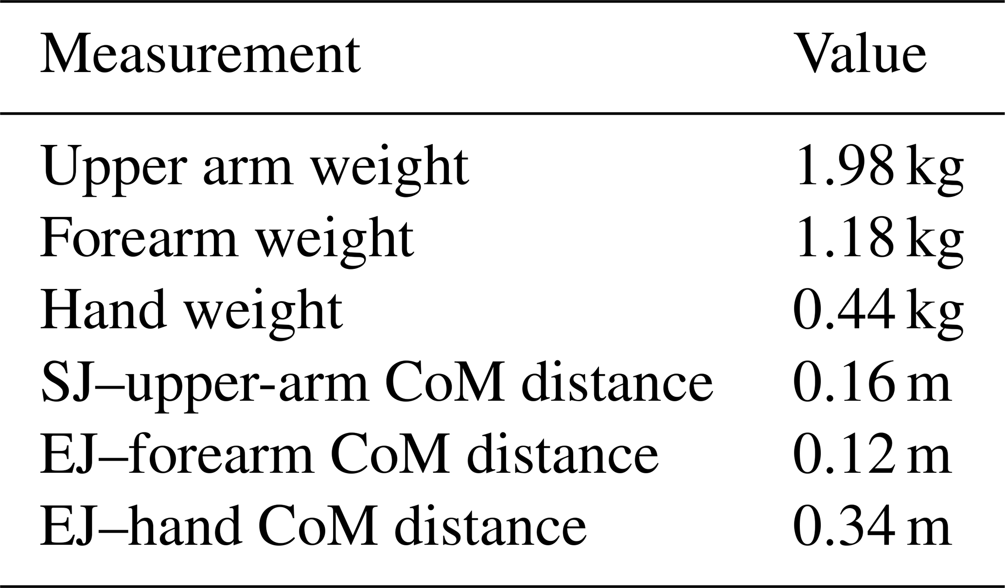
The overall objective of this study is to design a passive upper-limb exoskeleton to assist the worker during an overhead task. The shoulder torque generated by the arm weight depends on both the subject anthropometry and the rotations at the elbow and shoulder joints. The shoulder torque reaches its maximum value when the shoulder elevation angle θ1 and the elbow flexion–extension angle θ2 are, respectively, 90 and 0∘. The pattern of the gravitational torque due to the weight of the upper limb alone, shown in Fig. 1, is calculated thanks to the inertial parameters identified by Zatsiorsky (de Leva, 1996) and listed in Table 1 for a subject of 1.74 m height and body mass equal to 73 kg.
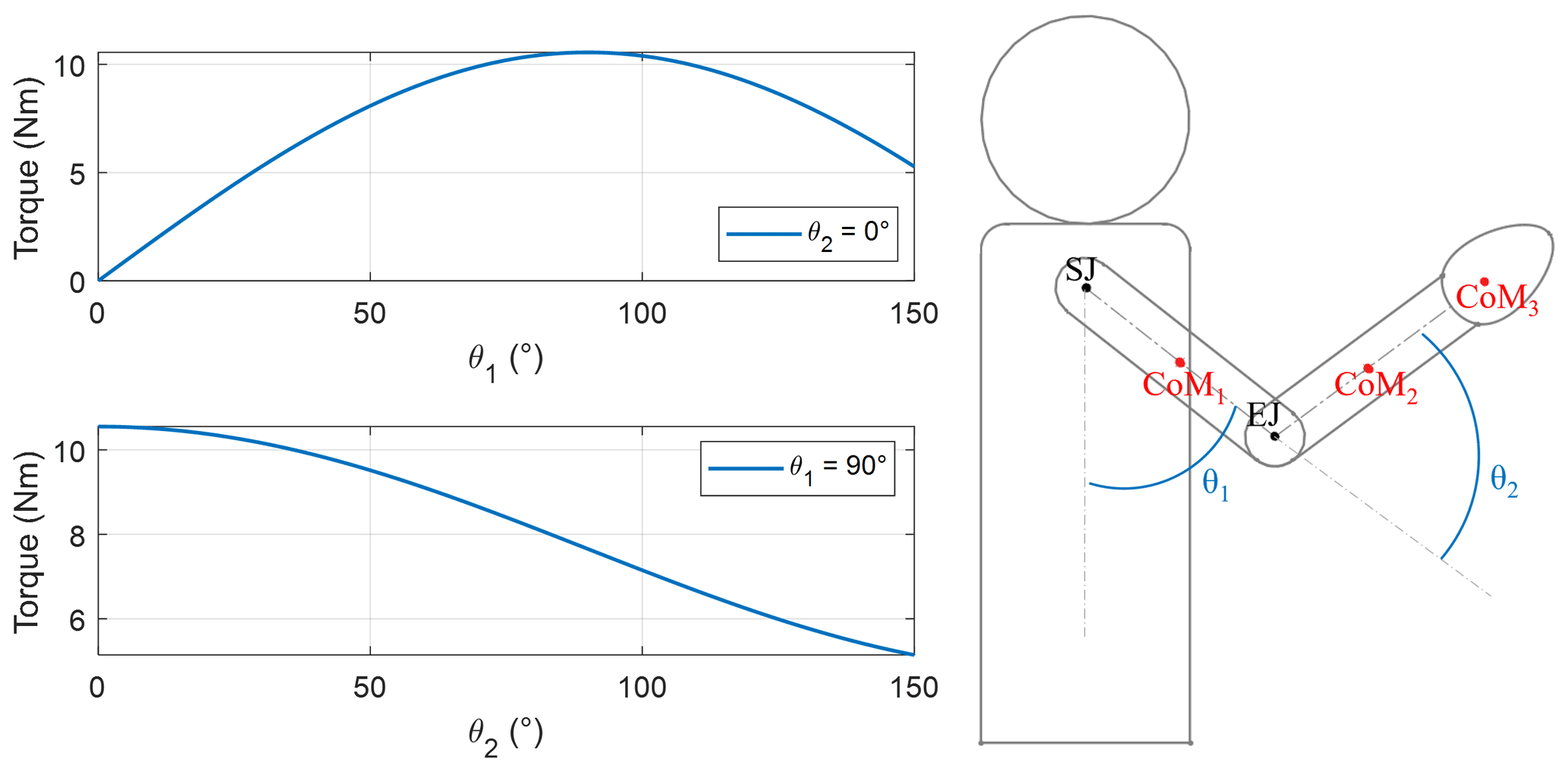
Figure 1Torque due to gravity with respect to the elevation angle of the upper arm θ1 and the forearm flexion angle θ2. SJ and EJ represent the glenohumeral (shoulder) joint center and the elbow joint center, respectively, whereas CoM1, CoM2, and CoM3 are the centers of mass of upper arm, forearm, and hand.
Table 1Anthropometric data used to estimate joint torque values in Fig. 1. SJ and EJ represent the glenohumeral (shoulder) joint center and the elbow joint center, respectively, whereas CoM is the center of mass of each segment.
To define the size of the pneumatic muscle and the architecture of the transmission system, the heaviest exoskeleton working condition is considered. Therefore, the system behavior is studied by changing the shoulder elevation angle (θ1∈ [90∘, 120∘]) while maintaining the elbow extended ().
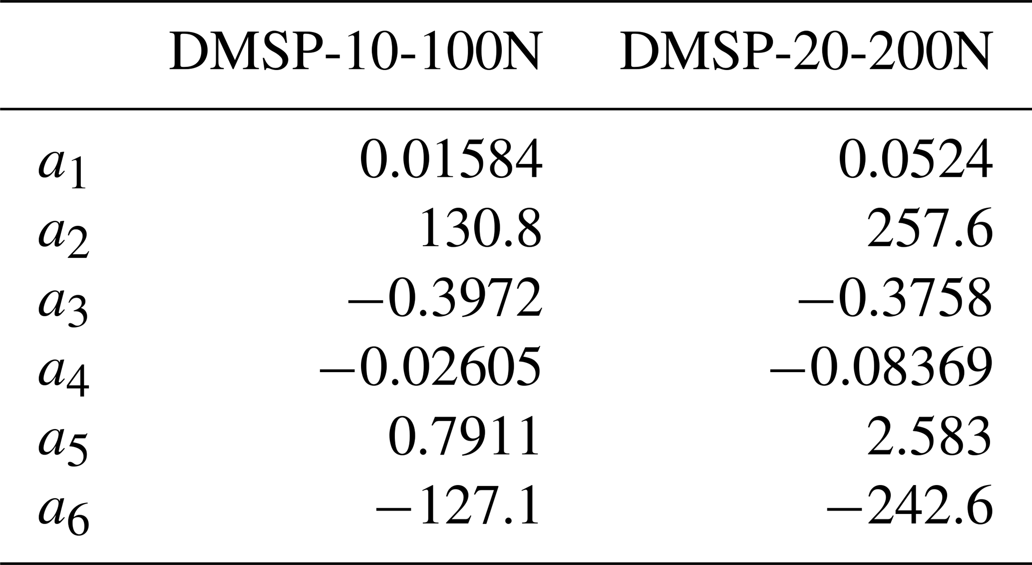
The tension force Fmu produced by a PAM is a function of many parameters, such as supply pressure p, diameter, and percentage of muscle contraction k. Therefore, two different sizes of the commercial McKibben artificial muscles (DMSP series, nominal length l0=0.21 m, FESTO, Germany) have been considered and tested for this application. The static characteristics of the PAMs tension force, shown in Fig. 2, are provided by the manufacturer and can be approximated by the modified Hill's muscle model proposed by Pitei and Tóthová (2016) and described by Eq. (1). The coefficients of the latter are obtained by interpolation and listed in Table 2.
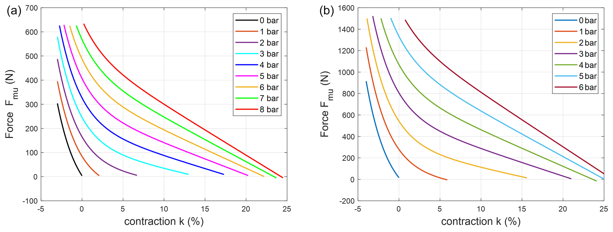
Figure 2Static characteristics of McKibben muscles: DMSP-10-100N series (a) and DMSP-20-200N series (b) from FESTO at different supply pressures.
The choice of the PAM is mainly driven by the maximum force required by the application as well as the desired shape of the force–contraction characteristic, which also depends on the size and the bulkiness of the actuator. However, PAMs generally have limited stroke; therefore, they require appropriate transmission systems to achieve a wide workspace. Moreover, the transmission system has a critical impact on the general performance of the device. Indeed, to perform in the desired way, the exoskeleton should exert a supporting torque as close as possible to the torque due to the gravitational load. This result cannot be achieved by the PAM itself; therefore, a transmission system able to adapt the characteristics of the McKibben muscle to the external load is necessary. To fulfill this requirement, two designs of the transmission system are evaluated, aiming at reducing the mismatch between the torque provided by the PAM and the gravitational torque throughout the range considered. In both cases, the pneumatic muscles are placed behind the back of the user, and the traction force is transmitted by the sliding of a tendon cable on a pulley (first case, Fig. 3a) or on a fixed cam centered at the glenohumeral joint (second case, Fig. 3b).
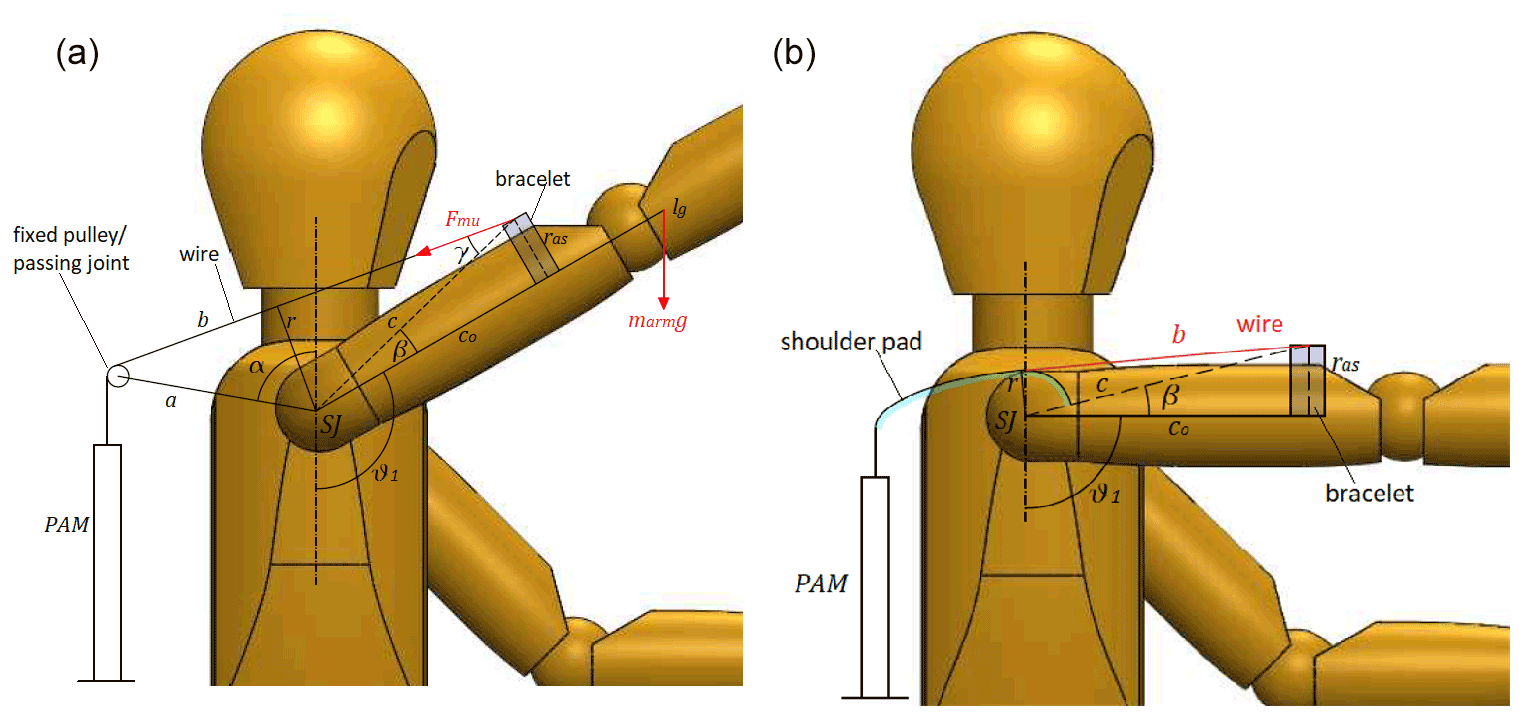
Figure 3Different designs of the exoskeleton: pulley-based design (a) and cam-based design (b).
Table 2Coefficients of Eq. (1) for approximating the static characteristics of commercial FESTO McKibben muscles.
2.2 A preliminary design of the transmission system based on pulley and cable
In the first case (named pulley-based design), a transmission based on cable and pulley (or a fixed passing point) is hypothesized to transmit the PAM tension force to the bracelet, located on the user's upper arm (Lo Piccolo et al., 2022). Concerning Fig. 3a, a, c0, α, and β are constant and define the size of the exoskeleton. The cable length b and the lever arm r of the tension force, instead, depended on the shoulder elevation angle θ1 and were calculated by the geometry through Eqs. (2) and (3) (Magnetti Gisolo et al., 2021; Lo Piccolo et al., 2022).
In the equations, A is the area of the triangle (a, b, c), while S is the semi-perimeter of the same triangle.
The variation of length b corresponds to the contraction of the pneumatic muscle. This allows for the evaluation, through Eq. (1), of the tensile force exerted by the PAM at different supply pressures. Finally, the torque provided by the exoskeleton is obtained.
2.3 The final cam-based design of the transmission system
A second architecture using a cam-based transmission system is also studied. To avoid the onset of forces that can cause discomfort or undesired movements of the limb, the cam center must coincide with the ideal center of the glenohumeral joint (Dehez and Sapin, 2011; Gull et al., 2020). In addition, the cam should not obstruct the user's view. To optimize the functionality of the overall architecture, a solution based on a cam radius increasing with the shoulder elevation angle is proposed. The tension force produced by the PAM and, consequently, the shoulder torque provided by the exoskeleton decrease with the contraction of the PAM. Therefore, the increase in the cam radius should partially balance the reduction of the maximum tensile force and extend the workspace of the exoskeleton. The cam design has been performed by the graphical approach described in detail by Magnetti Gisolo et al. (2021), briefly summarized in the following and shown in Fig. 4.

Figure 4Cam profile design obtained by graphical approach: by using DMSP-20-200N muscle (a), and DMSP-10-100N muscle (b). (c) Drawing of cam implementation in the exoskeleton.
Previous work (Magnetti Gisolo et al., 2021) showed a preliminary design of the cam profile, with an initial cam radius ri equal to 23.5 mm. This solution exhibited good performance; however, it can be considered only the result of a theoretical optimization approach. For the actual realization and integration of the cam within the final exoskeleton design, the initial cam radius should be greater than 34.5 mm, which represents the longitudinal distance between the acromion (highest point of the human shoulder complex) and the center of the shoulder joint (de Leva, 1996). For this reason, the theoretical result is compared to a more feasible solution that considered an initial cam radius set equal to 37 mm. By design specification, this value corresponds to the initial lever arm ri () of the muscle force. Starting from this initial condition, the two parameters do not coincide for any of the higher elevation angles. The initial contraction of the PAM ki is defined by considering the force–contraction characteristics for a nominal supply pressure (DMSP-10-100N: 4 bar; DMSP-20-200N: 2 bar), to balance the gravitational torque calculated at the initial condition. The behavior of the system is studied for elevation angles comprised between 90 and 120∘. For values higher than 120∘, the PAM reaches the end of its stroke. The muscle force lever arm at the maximum elevation angle (rf), instead, is tuned between 40 and 70 mm to achieve the best performance that can be reached by the PAM selected, given the characteristics shown in Fig. 2. Its value is selected also by considering that a large rf corresponds to a large cam radius, likely resulting in a solution hard to implement in the final structure. The cam profile has been obtained graphically by circular arc interpolation, ensuring the tangency between the profile itself and the cable trajectory for the initial and final elevation angles selected. The iterative process is repeated for two more intermediate positions (θ1=100 and ) that are arbitrarily selected. Finally, discrete data from the CAD files are imported into MATLAB; then, through a fourth-degree-polynomial interpolation function, the muscle force lever arm r, the free cable length b, and hence the percentage contraction k are calculated for each elevation angle within the working range. Finally, the muscle tension force and the muscle torque are evaluated, given in Eq. (1), and the analysis of the static equilibrium condition of the system is performed.
2.4 Assembly of the exoskeleton including the final cam-based transmission system
A preliminary assembly of the complete exoskeleton is shown in Fig. 5.
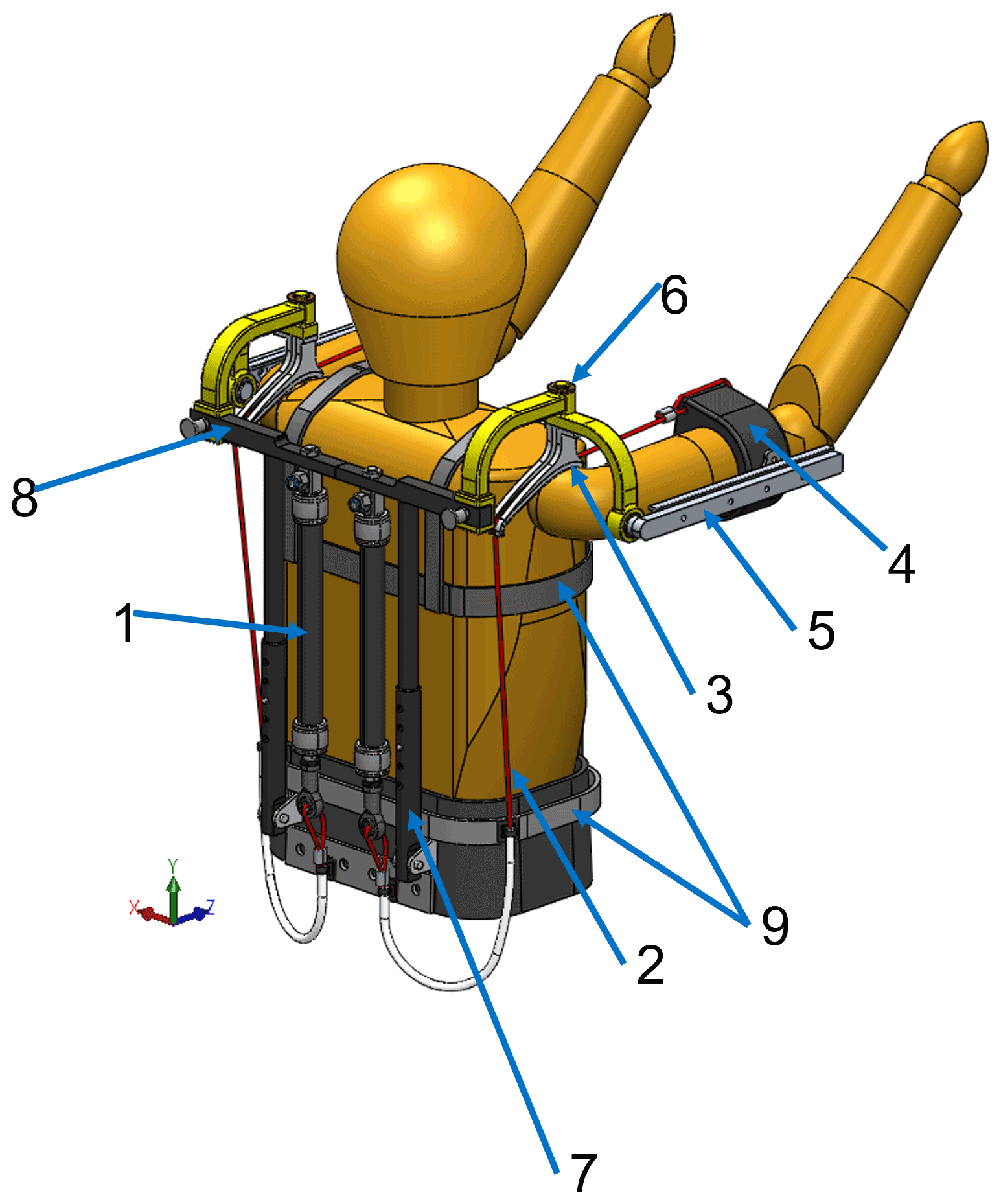
The PAM (1) is on the user's back. Its upper end is connected to the structure while the lower end is connected to a cable (2) that is wrapped around the shoulder pad (3) and connected to the bracelet (4) that supports the user's upper arm. This bracelet must be rigidly coupled to the structure of the exoskeleton to prevent sliding along the longitudinal direction of the arm due to large shear force. Moreover, the position of the bracelet with respect to the structure of the exoskeleton also depends on the anthropometry of the user; therefore, a telescopic linear guide (5) could be used to adjust the longitudinal position of the bracelet along the arm.
The human shoulder joint complex can be modeled as a 5 DoF joint: 3 rotations (flexion–extension; abduction–adduction; internal–external rotation) and 2 translations (elevation–depression and retraction–protraction). However, the first 2 rotational DoF, with larger ranges of motion, can be considered the most significant to comfortably carry out most of the work activities. For this reason, the exoskeleton architecture proposed integrates a universal joint (6) that replicates flexion–extension and abduction–adduction of the shoulder. To achieve the correct functionality, the two rotation axes of the mechanical joint shall be aligned with the glenohumeral joint axes, and their intersection shall coincide with the ideal center of such a joint, as shown in Fig. 6. The first arch of the universal joint is fixed to the frame, while the second one can rotate with respect to the first one, thanks to a bearing. This relative motion allows for the shoulder abduction–adduction. Then, a strut connects the bracelet to the moving arch, and its rotation with respect to the moving arch matches the flexion–extension of the shoulder joint. The shoulder pad is rigidly connected to the movable arch of the universal joint so that it can follow the user's limb during the arm abduction–adduction movement and limit friction between the cable and the cam profile.
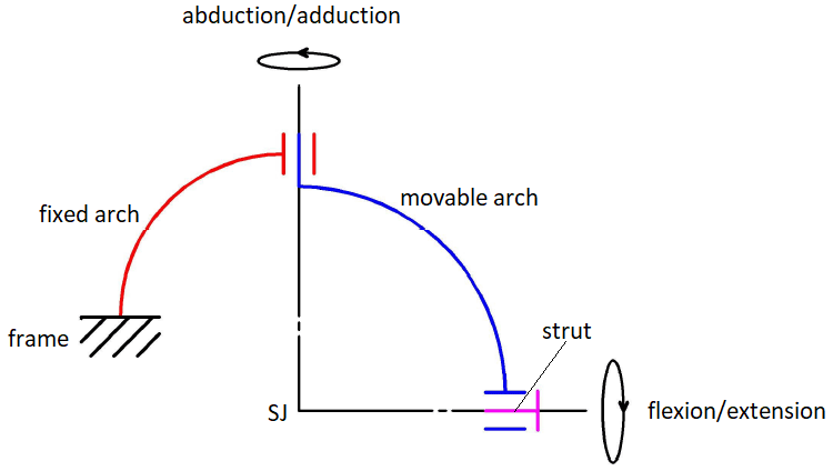
Figure 6Diagram of the universal joint in the frontal plane; SJ represents the center of the glenohumeral joint.
Finally, some adjustable systems are proposed to make the exoskeleton adaptable to different subjects' physical characteristics:
-
A telescopic rod (7) is proposed, positioned at the back of the subject, to adjust the vertical position of the shoulder pad;
-
A linear guide (8) is proposed, positioned at the back of the subject, to adjust horizontally the position of the universal joint with respect to the frame. To ease this process, the cable must be connected to the lower end of the actuator through a sheath and two heat clips. In this way, it is not necessary to align vertically the actuator and the cam;
-
A commercial harness (9) is proposed, used to support the rigid structures of the exoskeleton, allowing us to easily fit the exoskeleton to different users.
2.5 Simulations
Simulations were performed to analyze the two different commercial PAMs and the two transmission systems presented. The exoskeleton structure was based on the following geometrical parameters and conditions: c0=0.2 m, β=14, and θ2=0∘ (see Fig. 3a, b).
For the pulley-based design simulations, the constants a and α (shown in Fig. 3a) were set equal to 0.15 m and 80∘, respectively. As far as the cam-based design is concerned, the behavior of the device was tested for both the theoretical optimal value (ri=23.5 mm) and the actual feasible value selected (ri=37 mm) for the initial cam radius. The performance of the general system has been evaluated in different conditions of external load and supply pressure, for several combinations of shoulder elevation and elbow flexion–extension angles representative of the theoretical workspace of an exoskeleton for such applications. In particular, an unloaded condition, considering only the weight of the arm, and a loaded condition, with an additional 1 kg weight in the hand, were considered. All the simulations have been performed in the MATLAB environment.
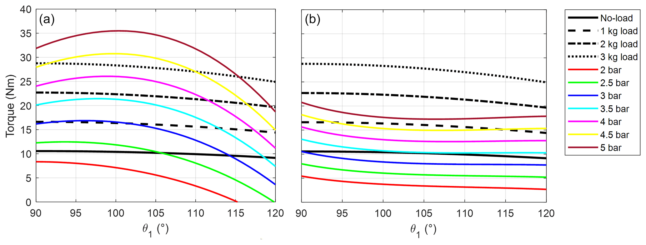
Figure 7Gravitational torque in no-load (black line) and 1 kg (dashed black line), 2 kg (dot-dashed black line), and 3 kg (dotted black line) loaded conditions as well as torque exerted by the exoskeleton (colored lines) at different supply pressures, by employing the DMSP-20-200N muscle. The plot in (a) refers to the pulley-based design of the transmission system, while the plot in (b) refers to the cam-based design considering the theoretical optimal value of ri=23.5 mm.
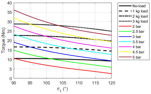
Figure 8Gravitational torque in no-load (black line) and 1 kg (dashed black line), 2 kg (dot-dashed black line), and 3 kg (dotted black line) loaded conditions as well as torque exerted by the exoskeleton at different supply pressures by employing the DMSP-20-200N muscle and the cam profile with ri=37 mm.
3.1 Comparison of FESTO PAMs
In the previous study (Magnetti Gisolo et al., 2021), the DMSP-20-200N pneumatic muscle had been tested in the pulley-based design and by employing the theoretical optimal value of cam initial radius (ri=23.5 mm). Figure 7 shows the torque values due to gravity in the unloaded and loaded conditions, along with the torque values exerted by the PAM at different supply pressures, for both solutions. The limited mismatch between the gravitational torque and that provided by the exoskeleton suggested that the cam-based solution can be more effective than the pulley-based design. In the cam-based solution (Fig. 7b), the exoskeleton provided most of the muscle work needed to raise the arms and hold the position. The remaining part, instead, can be easily provided by the user.
However, as discussed in Sect. 2.3, the cam with initial radius ri equal to 23.5 mm cannot be easily mounted over the user's shoulder. For this reason, the cam profile has been recalculated by increasing the initial radius. By considering the renewed, feasible cam profile obtained based on ri=37 mm, the trend of the torque values exerted by the exoskeleton is quite different with respect to the gravitational load (Fig. 8), causing higher efforts on the shoulder complex muscles to be balanced by the user. Therefore, the DMSP-20-200N McKibben muscle is not suitable for this application for any of the transmission systems tested (see Figs. 7a and 8). The cam-based mechanism (Fig. 8) partially reduces the mismatch, but the optimal performance could not be achieved due to the cam size.

Figure 9Gravitational torque in no-load (black line) and 1 kg (dashed black line), 2 kg (dot-dashed black line), and 3 kg (dotted black line) loaded conditions as well as torque exerted by the exoskeleton (colored lines) at different supply pressures, by employing the DMSP-10-100N muscle. The plot in (a) refers to the pulley-based design of the transmission system, while the plot in (b) refers to the cam-based design considering ri=37 mm.
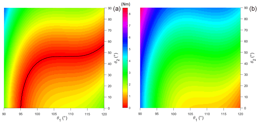
Figure 10Surface of the absolute difference of the torque due to gravity, with no load, and the torque generated by the DMSP-10-100N PAM, projected on plane π: ΔTorque = 0, by employing the shoulder pad at pressures of 5 (a) and 6 bar (b).
The adoption of a different PAM (FESTO DMSP-10-100N) highlights a significant increase in the performance of both transmission systems (Fig. 9). In the unloaded condition, the exoskeleton can balance at least 58 % of the gravitational torque with the pulley-based design (Fig. 9a), while the cam-based system provides at least 74 % of the gravitational torque (Fig. 9b). With respect to the results shown in Fig. 8, the torque values exerted by the more compact PAM (Fig. 9b) enable a significant reduction of the efforts required by the user to keep the upper limb lifted in the working position and allow them to obtain the best results among the tested configurations. As signaled by the curves presented in Fig. 9, through appropriate regulation of the supply pressure, the device action can be adapted to the weight of the user's arms and different operating conditions. On the other hand, the maximum force exerted by the PAM strongly depends on its size, and even at its maximum operating pressure (8 bar), the FESTO DMSP-10-100N PAM is not able to fully balance the gravitational torque with more than 2 kg of additional payload. However, since the proposed exoskeleton aims to support the user during repetitive lightweight overhead tasks, the more compact PAM can be considered appropriate for the intended application.
Finally, compared to the FESTO DMSP-20-200N (Fig. 8), higher pressure values (5 to 6 bar) are required to provide the required traction force and the corresponding supporting torque at the shoulder when a more compact PAM is chosen.
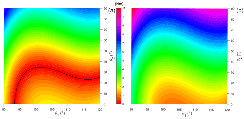
Figure 11Surface of the absolute difference of the torque due to gravity, in the loaded condition, and the torque generated by the DMSP-10-100N PAM, projected on plane π: ΔTorque = 0, by employing the shoulder pad at pressures of 7 (a) and 8 bar (b).
3.2 Workspace evaluation and discussion for different loading conditions and supply pressures
In this section, the torque provided by the cam-based mechanism, employing the FESTO DMSP-10-100N actuator, is evaluated by varying both the elevation angle of the upper arm (θ1) and the elbow flexion–extension angle (θ2). The ranges selected are θ1∈ [90∘, 120∘], as considered in Sect. 3.1, and θ2∈ [0∘, 90∘], since larger elbow flexion angles are unlikely maintained during overhead tasks.
The absolute difference between the two torque values is calculated for each position inside the theoretical workspace, providing the residual torque that the shoulder complex muscles must provide to lift or to lower the upper limb from each equilibrium position. The results of the analysis for the unloaded condition are shown in Fig. 10 when the DMSP-10-100N pneumatic muscle is pressurized at 5 bar (Fig. 10a) or 6 bar (Fig. 10b). Those values are selected given the results of the simulations discussed in Sect. 3.1 (Fig. 9b). The surface ΔTorque, obtained as the absolute difference between the gravitational torque and the one generated by the PAM, was projected in a “horizontal” plane π: ΔTorque = 0. In Fig. 10a, the black line represents the configuration within the theoretical workspace that corresponds to the static equilibrium condition, in which there is no effort on the user's shoulder muscles since the two torque values are equal. When a supply pressure equal to 6 bar is selected (Fig. 10b), no static equilibrium condition is achieved throughout the workspace, yet no black line is shown. The same result is highlighted in Fig. 9b, where no intersection between the gravitational torque and the torque provided by the device is observed for the θ2=0 condition. This result confirms the necessity for an appropriate selection of the supply pressure when a stable equilibrium position is required. However, due to the limited magnitude of the residual torque shown for most of the positions inside the workspace (Fig. 10), the worker is expected to provide such a difference during operation by their muscle strength.
Figure 11 reports the effort required from the user in loaded condition by pressurizing the DMSP-10-100N muscle at higher supply pressures (7 bar, Fig. 11a, and 8 bar, Fig. 11b). Higher pressures, with respect to the ones selected in the unloaded condition (see Fig. 10), are required to provide the balancing torque due to the participation of the additional external load. In both Figs. 10 and 11, the area surrounding each black line corresponds to low values of residual torque that are requested from the user to move the arm away from the equilibrium condition. Especially in the unloaded condition (Fig. 10), the area corresponding to low values of residual torque (up to 2.5–3 Nm) is large enough to cover the theoretical workspace for the most part. In this condition, we can assume that the real workspace of the exoskeleton is rather comparable to the theoretical one. In the loaded condition (Fig. 11), the workspace seems to be narrower. At such high supply pressures, even small variations of the PAM tensile force generate large variations in its length and consequently in the free cable length. Although the exoskeleton is no longer able to guarantee the desired arm elevation angle value with the same level of performance obtained in the unloaded condition, it is still allowed to reach high elevation angles and elbow flexion–extension angles up to 50∘, which might be appropriate for most of the applications considered.
In this paper, a novel passive exoskeleton based on McKibben PAMs has been presented, which aimed at assisting workers during overhead tasks. The use of pneumatic artificial muscles rather than elastic passive elements has provided additional flexibility to the solution, given the availability of these actuators in different sizes, load capabilities, and nonlinear force–contraction characteristics. Moreover, the intrinsic deformability of PAMs and their relatively simple use and low cost represent relevant aspects that may help in the adoption of these devices in such applications.
In order to adjust the characteristic of the PAM to the specific application, i.e., the support of the gravitational load due to raised arms during work, a specific cam-based design of the transmission system has been presented. This solution has been discussed and compared to a former design based on cable and pulley. The cam-based design improves the overall performance of the exoskeleton by increasing both the effort support and the upper-limb range of movement. Different commercial PAMs have been also tested by simulations: in particular, by comparing the results of two FESTO pneumatic muscles, the DMSP-10-100N model has proven to be the best choice for the loading conditions tested. The performance of the system has been assessed for a supply pressure between 0 and 8 bar, delivering an evaluation of the workspace of the system, in terms of shoulder elevation angle and elbow flexion–extension angle.
Finally, a first assembly of the final exoskeleton has been presented. The exoskeleton structure must be as lightweight and as simple as possible. In addition, it must adapt to the user's anthropometric characteristics. Assuming the use of high-performance mechanical aluminum alloys for the realization of all structural components, the weight of the exoskeleton is about 6 kg. The estimated mass is greater than that of commercial passive upper-limb exoskeletons and could negatively affect the perceived effort of the lower back and legs. However, this is only a preliminary design. Further structural analysis will be necessary to optimize the architecture of the exoskeleton and to choose the most appropriate materials. In addition, a multibody model could help to study the following: the pressure distribution in the contact areas between the exoskeleton and the user (e.g., the bracelet), the motion of the exoskeleton components relative to the body segments, and the possible alterations to joint angles trajectories. Indeed, all these factors can cause discomfort and pain for prolonged tasks.
The solution presented seems to be promising; however, further work is necessary to assess the performance of the system in a real scenario. In particular, the same considerations done for model simulations in the current work will be verified in the field when a prototype of the system will be manufactured. In particular, the potential contribution of friction in the transmission system that was neglected in the simulations might alter the real force exerted by the PAM, affecting the supporting functionality of the device. Similarly, pneumatic losses and the exoskeleton weight might affect the overall behavior. Moreover, to further enhance the short stroke of the PAM, a cable-based transmission including a reduction system could be helpful and should be considered in the next versions of the design. A second parallel passive device could also be considered to increase the actual workspace of the system.
All data included in this study are available upon request from the corresponding author.
SMG developed the methodology with contributions by all the co-authors; MP and CDB contributed to the model simulations and discussion of the results. MP, SMG, and CDB prepared the original draft; GGM and CF reviewed and edited the article.
The contact author has declared that neither they nor their co-authors have any competing interests.
Publisher’s note: Copernicus Publications remains neutral with regard to jurisdictional claims in published maps and institutional affiliations.
This article is part of the special issue “Advances in Service and Industrial Robotics – RAAD2021”. It is a result of the 30th International Conference on Robotics in Alpe-Adria-Danube Region, RAAD 2021, Futuroscope-Poitiers, France, 21–23 June 2021.
This paper was edited by Mohamed Amine Laribi and reviewed by Domenico Mundo and one anonymous referee.
Altenburger, R., Scherly, D., and Stadler, K. S.: Design of a passive, iso-elastic upper limb exoskeleton for gravity compensation, Robomech J., 3, 1–7, https://doi.org/10.1186/s40648-016-0051-5, 2016.
Angold, R., Lubin, J., Solano, M., Paretich, C., and Mastaler, T.: Exoskeleton and method of providing an assistive torque to an arm of a wearer, CA2952403A1, 2017.
Bai, S., Christensen, S., and Islam, M. R. U.: An upper-body exoskeleton with a novel shoulder mechanism for assistive applications, 2017 IEEE Int. Conf. Adv. Intell. Mech., 1041–1046, https://doi.org/10.1109/AIM.2017.8014156, 2017.
Balasubramanian, S., Wei, H. R., Perez, M., Shepard, B., Koeneman, E., Koeneman, J., and He, J.: Rupert: An exoskeleton robot for assisting rehabilitation of arm functions, in: 2008 Virtual Rehabilitation, IWVR, https://doi.org/10.1109/ICVR.2008.4625154, 163–167, 2008.
Cui, X., Chen, W., Jin, X., and Agrawal, S. K.: Design of a 7-DOF Cable-Driven Arm Exoskeleton (CAREX-7) and a Controller for Dexterous Motion Training or Assistance, IEEE/ASME Trans. Mech., 22, 161–172, https://doi.org/10.1109/TMECH.2016.2618888, 2017.
Dehez, B. and Sapin, J.: ShouldeRO, an alignement-free two-DOF rehabilitation robot for the shoulder complex, in: 2011 IEEE International Conference of Rehabilitation Robotics, IEEE, 8 pp., https://doi.org/10.1109/ICORR.2011.5975339, 2011.
de Leva, P.: Adjustments to Zatsiorsky-Seluyanov's segment inertia parameters, J. Biomech., 29, 1223–1230, https://doi.org/10.1002/ima.22019, 1996.
de Vries, A., Murphy, M., Könemann, R., Kingma, I., and de Looze, M.: The Amount of Support Provided by a Passive Arm Support Exoskeleton in a Range of Elevated Arm Postures, IISE Trans. Occup. Ergon. Hum. Factors, 7, 311–321, https://doi.org/10.1080/24725838.2019.1669736, 2019.
Doyle, M. C.: Adaptive arm support systems and methods for use, US20120184880A1, 2013.
Ebrahimi, A.: Stuttgart Exo-Jacket: an Exoskeleton for Industrial Upper Body Applications, 2017 10th Int. Conf. Hum. Syst. Interact., 258–263, https://doi.org/10.1109/HSI.2017.8005042, 2017.
Gopura, R. A. R. C. and Kiguchi, K.: Mechanical designs of active upper-limb exoskeleton robots state-of-the-art and design difficulties, in: 2009 IEEE International Conference on Rehabilitation Robotics, IEEE, ICORR 2009, https://doi.org/10.1109/ICORR.2009.5209630, 178–187, 2009.
Gull, M. A., Bai, S., and Bak, T.: A review on design of upper limb exoskeletons, Robotics, 9, 1–35, https://doi.org/10.3390/robotics9010016, 2020.
Hall, S. J.: Basic Biomechanics, 6th Edn., edited by: Johonson, C. and Hash, D. B., McGraw-Hill, New York, 2011.
Kim, S., Nussbaum, M. A., Mokhlespour Esfahani, M. I., Alemi, M. M., Alabdulkarim, S., and Rashedi, E.: Assessing the influence of a passive, upper extremity exoskeletal vest for tasks requiring arm elevation: Part I – “Expected” effects on discomfort, shoulder muscle activity, and work task performance, Appl. Ergon., 70, 315–322, https://doi.org/10.1016/j.apergo.2018.02.025, 2018.
Klein, J., Spencer, S. J., Allington, J., Minakata, K., Wolbrecht, E. T., Smith, R., Bobrow, J. E., and Reinkensmeyer, D. J.: Biomimetic orthosis for the neurorehabilitation of the elbow and shoulder (BONES), in 2008 2nd Biennial IEEE RAS & EMBS International Conference on Biomedical Robotics and Biomechatronics, IEEE, 535–541, https://doi.org/10.1109/BIOROB.2008.4762866, 2008.
Lo, H. S. and Xie, S. Q.: Exoskeleton robots for upper-limb rehabilitation: State of the art and future prospects, Med. Eng. Phys., 34, 261–268, https://doi.org/10.1016/j.medengphy.2011.10.004, 2012.
Lo Piccolo, M. V., Muscolo, G. G., and Ferraresi, C.: Use of Pneumatic Artificial Muscles in a Passive Upper Body Exoskeleton, MESROB 2021, in press, 2022.
Magnetti Gisolo, S., Muscolo, G.G., Paterna, M., De Benedictis, C., and Ferraresi, C.: Feasibility Study of a Passive Pneumatic Exoskeleton for Upper Limbs Based on a McKibben Artificial Muscle, in: Advances in Service and Industrial Robotics, edited by: Zeghloul, S., Laribi, M. A., and Sandoval, J., RAAD 2021, Mechanisms and Machine Science, Vol. 102, Springer, Cham., https://doi.org/10.1007/978-3-030-75259-0_23, 2021.
Mauri, A., Lettori, J., Fusi, G., Fausti, D., Mor, M., Braghin, F., Legnani, G., and Roveda, L.: Mechanical and control design of an industrial exoskeleton for advanced human empowering in heavy parts manipulation tasks, Robotics, 8, 65, https://doi.org/10.3390/robotics8030065, 2019.
Maurice, P., Ivaldi, S., Babic, J., Camernik, J., Gorjan, D., Schirrmeister, B., Bornmann, J., Tagliapietra, L., Latella, C., Pucci, D., and Fritzsche, L.: Objective and Subjective Effects of a Passive Exoskeleton on Overhead Work, IEEE Trans. Neural Syst. Rehabil. Eng., 28, 152–164, https://doi.org/10.1109/TNSRE.2019.2945368, 2020.
Moisè, M., Morelli, L., Giovacchini, F., Vitiello, N., and Colombina, G.: System for assisting an operator in exerting efforts, WO/2019/016629, 2019.
Otten, B. M., Weidner, R., and Argubi-Wollesen, A.: Evaluation of a Novel Active Exoskeleton for Tasks at or above Head Level, IEEE Robot. Autom. Lett., 3, 2408–2415, https://doi.org/10.1109/LRA.2018.2812905, 2018.
Pacifico, I., Scano, A., Guanziroli, E., Moisè, M., Morelli, L., Chiavenna, A., Romo, D., Spada, S., Colombina, G., Molteni, F., Giovacchini, F., Vitiello, N., and Crea, S.: An Experimental Evaluation of the Proto-MATE: A Novel Ergonomic Upper-Limb Exoskeleton to Reduce Workers' Physical Strain, IEEE Robot. Autom. Mag., 27, 54–65, 2020.
Pardoel, S. and Doumit, M.: Development and testing of a passive ankle exoskeleton, Biocybern. Biomed. Eng., 3, 902–913, https://doi.org/10.1016/j.bbe.2019.08.007, 2019.
Park, H.-S., Ren, Y., and Zhang, L.-Q.: IntelliArm: an Exoskeleton for Diagnosis and Treatment of Patients with Neurological Impairments, in: 2008 2nd Biennial IEEE RAS & EMBS International Conference on Biomedical Robotics and Biomechatronics, IEEE, 109–114, https://doi.org/10.1109/BIOROB.2008.4762876, 2008.
Pitei, J. and Tóthová, M.: Modelling of pneumatic muscle actuator using Hill's model with different approximations of static characteristics of artificial muscle, in: MATEC Web of Conferences, 76, 02015, https://doi.org/10.1051/matecconf/20167602015, 2016.
Spada, S., Ghibaudo, L., Gilotta, S., Gastaldi, L., and Cavatorta, M. P.: Investigation into the Applicability of a Passive Upper-limb Exoskeleton in Automotive Industry, Procedia Manuf., 11, 1255–1262, https://doi.org/10.1016/j.promfg.2017.07.252, 2017.
Stadler, K. S., Altenburger, R., Schmidhauser, E., Scherly, D., Ortiz, J., Toxiri, S., Mateos, L., and Masood, J.: Robo-mate an exoskeleton for industrial use – Concept and mechanical design, Adv. Coop. Robot. Proc. 19th Int. Conf. Climbing Walk. Robot. Support Technol. Mob. Mach. CLAWAR 2016, World Scientific, 806–813, https://doi.org/10.1142/9789813149137_0094, 2016.
Sylla, N., Bonnet, V., Colledani, F., and Fraisse, P.: Ergonomic contribution of ABLE exoskeleton in automotive industry, Int. J. Ind. Ergon., 44, 475–481, https://doi.org/10.1016/j.ergon.2014.03.008, 2014.
Tsagarakis, N. G. and Caldwell, D. G.: Development and control of a “soft-actuated” exoskeleton for use in physiotherapy and training, Auton. Robots, 15, 21–33, https://doi.org/10.1023/A:1024484615192, 2003.
Wang, H.-M., Le, D. K. L., and Lin, W.-C.: Evaluation of a Passive Upper-Limbs Exoskeleton Applied to Assist Farming Activities in Fruit Orchards, Appl. Sci., 11, 757, https://doi.org/10.3390/app11020757, 2021.