the Creative Commons Attribution 4.0 License.
the Creative Commons Attribution 4.0 License.
 | 14 Jul 2026

Research on kinematics and fractional order active disturbance rejection control of skating training robot
Baihang Wang
Xue Zhao
Yihang Gong
Longchao Sun
Zi Yang
Speed skating training imposes rigorous requirements on movement accuracy and dynamic stability. Traditional training relies heavily on coaches' subjective experience; exoskeleton robots suffer from limitations of large additional inertia and insufficient flexibility. Although cable-driven robots possess the advantage of flexible transmission, existing control methods fail to meet the demand for high-precision trajectory tracking. To address this issue, this study conducted systematic research: a cable-driven robotic mechanism adapted for skating training was designed, and a geometric model of fixed-mobile coordinate systems was established, with the Newton–Raphson iterative method employed to solve forward and inverse kinematic equations. An improved fractional-order active disturbance rejection control (FOADRC) strategy was proposed, which removes the tracking differentiator of traditional ADRC and integrates a fractional-order extended state observer (FOESO) with a fractional-order PD control law, thereby enhancing dynamic response and anti-disturbance capability. Human skating movement data were collected using the NOKOV infrared motion capture system, and reference trajectories were generated via fitting with eighth-order Fourier series. Comparative simulations with traditional PID control were performed. The results demonstrate that the motor angle tracking error under the FOADRC strategy is significantly reduced, with improved control precision. This study provides a practical solution for precise skating training and offers reference value for the development of intelligent auxiliary equipment in competitive sports.
- Article
(3485 KB) - Full-text XML
- BibTeX
- EndNote


In the field of ice and snow competitive sports, speed skating and short track speed skating impose stringent requirements on athletes' explosive power, endurance, coordination, and movement precision. Traditional training models rely heavily on coaches' subjective experience for evaluation, suffering from inherent limitations including insufficient personalization of training plans, delayed feedback on training effects, and limited precision in load regulation. These drawbacks render them incompetent in meeting the demands of scientific training in modern competitive sports (Buiter, 2020). With the advancement of artificial intelligence and robotics technology, intelligent auxiliary training robots have emerged as a pivotal solution to break through the bottlenecks of traditional training. By accurately perceiving real-time motion states and dynamically regulating training loads, these robots can achieve closed-loop optimization of personalized training programs and significantly enhance training efficacy.
Current mainstream exoskeleton training robots, constrained by their rigid link structures, require drive units to be mounted in close proximity to joints. This results in substantial additional inertia and bulkiness of the system (Barnett et al., 2023), which not only increases the athletes' movement burden but also may constrain movement flexibility (Iverach-Brereton et al., 2014), making them incompatible with the high-speed dynamic characteristics of skating (Lu et al., 2026, 2025). In contrast, cable-driven robots, leveraging the structural advantage of decoupling drive units from the human body, transmit force and motion through lightweight, high-strength cables. They not only eliminate the adverse impact of additional inertia on movement flexibility but also utilize the compliance of cables to mitigate the risk of rigid collisions (Song et al., 2025). Meanwhile, they possess merits such as a large workspace, efficient force transmission, and minimal error accumulation, thus serving as an ideal mechanical carrier for high-precision control in skating training (Alwan et al., 2025; Li and Yao, 2025). Although scholars have conducted relevant research on cable-driven robots (e.g., the trunk balance trainer TruST), the ankle rehabilitation mechanism (Khan et al., 2017), and the gait simulation robot MotionMaker (Zhang et al., 2024), most of these studies focus on stability maintenance in rehabilitation training or simulation of basic movements with relatively simplistic control strategies. If applied to skating training, they fail to adequately account for the nonlinear coupling, instantaneous disturbances, and high-precision trajectory tracking requirements arising from complex scenarios in skating – such as high-speed ice pushing, dynamic balance adjustment, and fluctuations in ice friction – making direct migration to competitive skating training scenarios infeasible.
Control strategy is the core determinant of the performance of cable-driven skating training robots. Although integer-order PID controllers are widely adopted in mechanical systems due to their simple structure and strong robustness, their tracking accuracy and anti-disturbance capability are no longer sufficient to meet high-precision training requirements when confronting dynamic disturbances (e.g., sudden changes in ice friction, movement disturbances from trainers) and the nonlinear coupling characteristics of the system during skating training (Koukolová, 2015). Active disturbance rejection control (ADRC) offers an effective solution for nonlinear system control via real-time estimation and compensation for internal and external disturbances via an extended state observer (ESO) (Koukolová, 2015). However, traditional nonlinear ADRC suffers from complex parameter tuning and heavy computational load. Linear active disturbance rejection control (LADRC) simplifies parameter adjustment by linearizing the ESO (Chen et al., 2018), and subsequent scholars have further proposed improved schemes such as adaptive LADRC and full-state feedback ADRC, which have validated their anti-disturbance advantages in scenarios like hydraulic servo systems and electromechanical actuators (Tan and Fu, 2016; Yao and Deng, 2017). Nevertheless, the tracking differentiator (TD) in traditional ADRC and LADRC induces delays in dynamic response, making it difficult to adapt to the control requirements of high-frequency movements in skating, such as rapid ice pushing and sudden stops with direction changes.
The development of fractional-order control theory provides a novel pathway to overcome the limitations of integer-order control. By introducing non-integer-order calculus operators, it enables adjustable slopes of integral amplitude-frequency characteristics and enhances the high-frequency noise suppression capability of differential links. Compared with integer-order PID controllers, it exhibits superior performance in response speed, robustness, and adaptability to complex disturbances (Liu et al., 2020; Luo et al., 2014). Existing studies have applied fractional-order PID to scenarios such as hard disk drive servo systems and light rail vehicle torque control, verifying its effectiveness in improving tracking accuracy and anti-disturbance performance (Liu et al., 2020; Luo et al., 2014). Yet, most existing research on the integration of fractional-order control and ADRC focuses on general mechanical systems, failing to fully consider the unique characteristics of cable-driven skating training robots – including multi-cable coordination, strong dynamic disturbances, and stringent requirements for trajectory tracking accuracy. There is a lack of dedicated design and validation of control strategies specifically tailored to this scenario, resulting in a significant mismatch gap between existing control methods and the high-precision demands of skating training.
To bridge this critical gap, this study proposes a novel cable-driven skating training robot and FOADRC strategy targeting its high-precision trajectory tracking requirements, conducting a full-process investigation from mechanism modeling to control verification. First, a cable-driven robotic mechanism adapted to skating training scenarios is designed, and a geometric model under fixed-mobile coordinate systems is established. The forward and inverse kinematic equations of the robot are derived and solved using the Newton–Raphson iterative method to ensure that the accuracy of the kinematic model meets the requirements for control strategy design. Furthermore, a hybrid control strategy integrating ADRC and fractional-order control is proposed to enhance control tracking accuracy. To validate the effectiveness of the proposed method, motion data of key lower limb joints during skating will be collected via the NOKOV infrared motion capture system as control inputs, and experiments will be conducted on the permanent magnet synchronous motor (PMSM) drive unit to systematically verify its superiority in trajectory tracking accuracy. This study aims to provide a novel method and practical reference for the control strategies of similar intelligent auxiliary equipment in the field of competitive sports.
2.1 Overall structure of the cable-driven skating training robot
The skating training robot is an intelligent auxiliary device specifically designed to improve the lower limb strength and movement coordination of speed skaters. Its core objective is to achieve precise training of high-difficulty competitive movements through human–robot collaboration. The design followed three core principles: first, the mechanism must accurately match the technical indicators of professional training; second, all parts in contact with the athlete's body must balance safety and comfort for long-term wear; third, the entire machine must possess practical attributes of easy maintenance, easy deployment, and easy operation. Based on the above principles, the overall layout of the final cable-driven skating training robot is shown in Fig. 1.
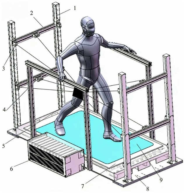
Figure 1Structure diagram of skating training robot. 1 – column; 2 – column crossbeam; 3 – pulley; 4 – handrails; 5 – calf strap; 6 – servo driver; 7 – chassis cover version; 8 – chassis; 9 – mirror surface.
Structurally, the robot consists of eight functional modules: (1) columns – as the vertical supporting framework of the entire system, they bear the main load; (2) column crossbeams – horizontally connecting the left and right columns to form a stable gantry frame; (3) pulleys – distributed on the inner sides of the columns and crossbeams, used to guide and change the direction of the cables, ensuring a smooth and efficient force transmission path; (4) handrails – symmetrically arranged on both sides of the athlete's arms, adopting an ergonomic curved surface design that is not only easy to grasp but also provides real-time balance compensation during high-speed skating; (5) servo drivers – installed inside the chassis, real-time feedback of cable tension and displacement through high-precision encoders to achieve millisecond-level response; (6) chassis cover plates – made of lightweight and high-strength composite materials, which not only protect internal components but also facilitate quick disassembly and maintenance; (7) chassis – integrating a counterweight and shock absorption system to ensure the entire machine remains stable under the athlete's explosive ice-pushing movements; (8) mirror surface – its surface undergoes special polishing treatment, with a friction coefficient similar to that of real ice, enabling the athlete to obtain an immersive training experience both visually and tactilely. In addition, the entire system is connected to key parts of the athlete's waist, legs, and ankles through multiple high-strength and low-extension cables, forming a closed-loop force control network.
In terms of the drive configuration, the robot abandoned conventional rigid linkages in favor of a servo motor-cable hybrid drive scheme. The drive unit was composed of an S7-1200 PLC, a 60ASM400 permanent magnet synchronous motor (PMSM) with a rated power of 400 W and a rated speed of 3000 rpm, and a type 1204 ball screw, as illustrated in Fig. 2. Based on the real-time collected posture data of the athlete, the servo motors dynamically adjusted the magnitude and direction of the output force of each cable. This design not only provided upward lifting assistance during the athlete's take-off phase but also applied controllable damping at the moment of ice landing, thereby effectively mitigating joint impact. This flexible drive strategy not only significantly reduced the mechanism inertia but also greatly enhanced the safety redundancy of training.
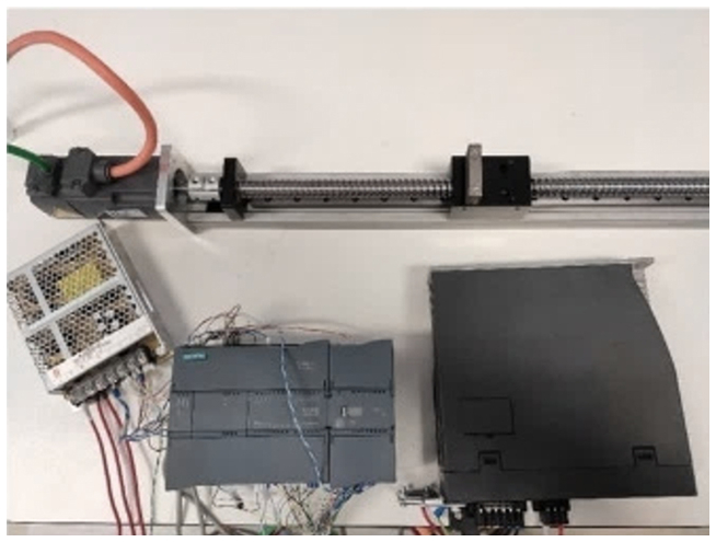
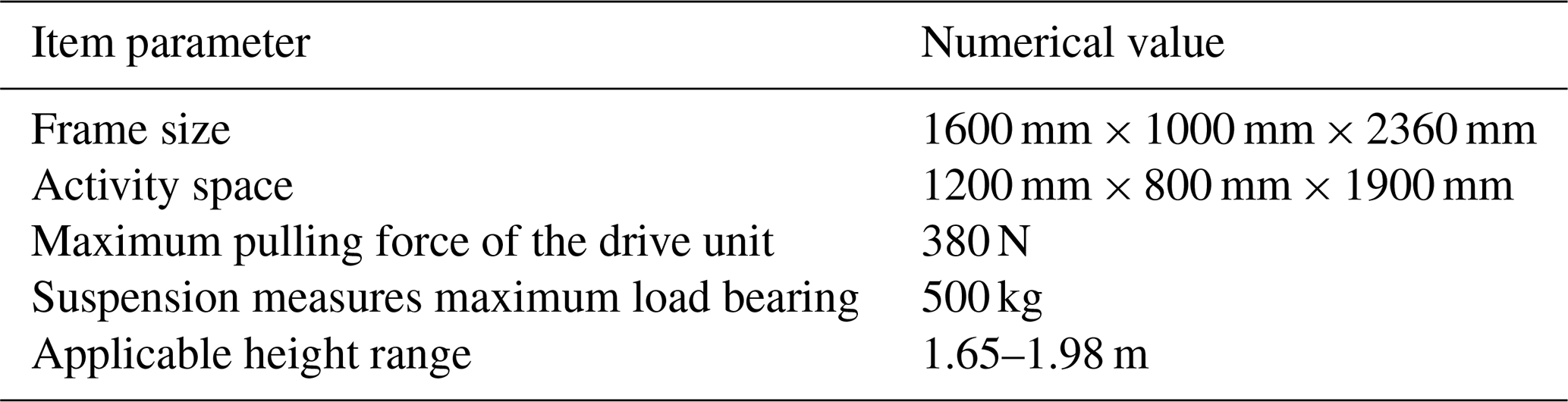
In terms of the driving method, the robot abandons the traditional rigid links and adopts a servo motor-cable composite driving scheme. Based on the real-time collected athlete's posture data, the servo motor dynamically adjusts the output force magnitude and direction of each cable. It can not only provide upward lifting assistance during the athlete's take-off phase but also apply controllable damping at the moment of ice landing, effectively reducing joint impact. This flexible driving strategy not only significantly reduces the mechanism inertia but also greatly improves the safety redundancy of training. The selection of the key technical parameters for the system is rigorously grounded in a combination of biomechanical design principles and practical engineering requirements. Specifically, the applicable height range (1.65–1.98 m) and the designated activity space are scaled to accommodate the anthropometric data of professional speed skaters and their extensive dynamic range of motion during the low-posture ice-pushing phase. To guarantee structural reliability, the maximum pulling force of the drive unit (380 N) and the suspension's maximum load-bearing capacity (500 kg) are engineered to incorporate a robust safety margin, safely withstanding the peak dynamic impact loads generated by athletes' explosive instantaneous forces. Furthermore, the overall frame size is optimized to balance the necessity of an immersive, broad training workspace with the spatial deployment constraints of standard indoor sports facilities. The main structural parameters of the cable-driven ice-skating training robot are presented in Table 1.
2.2 Simplified model of ice skating training robot
To conduct systematic kinematic modeling of the skating training robot, the primary task is to establish an accurate mapping relationship between the pose (position and attitude) of the moving platform in space and the real-time lengths of the eight cables. Figure 3 shows a simplified model of the robot mechanism. For this purpose, a fixed coordinate system O-XYZ and a follower coordinate system p-xyz were introduced as the description benchmarks respectively. The fixed coordinate system O-XYZ was set at the geometric center of the rectangular plane formed by the surface of the robot's bottom frame, where the origin O is the centroid of the rectangle. The orientation rules of the coordinate axes are as follows: the Z axis is perpendicular to the plane A5A6A7A8 and points upward; the X axis is parallel to A5A6, with its positive direction pointing from A5 to A6; the Y axis is determined according to the right-hand rule. The moving coordinate system p-xyz is fixed on the moving platform at the center of the athlete's thigh, and its origin p is located at the geometric center of the rectangular plane a5a6a7a8 formed by the lower surface of the moving platform. The axis directions of this coordinate system follow the same definition logic as the fixed coordinate system: the z axis is perpendicular to the plane a5a6a7a8 and points upward; the x axis is parallel to the side a5a6, with the positive direction pointing from a5 to a6; the y axis is also determined according to the right-hand rule to ensure that the two coordinate systems have consistent directions in the initial state, facilitating subsequent coordinate transformations.
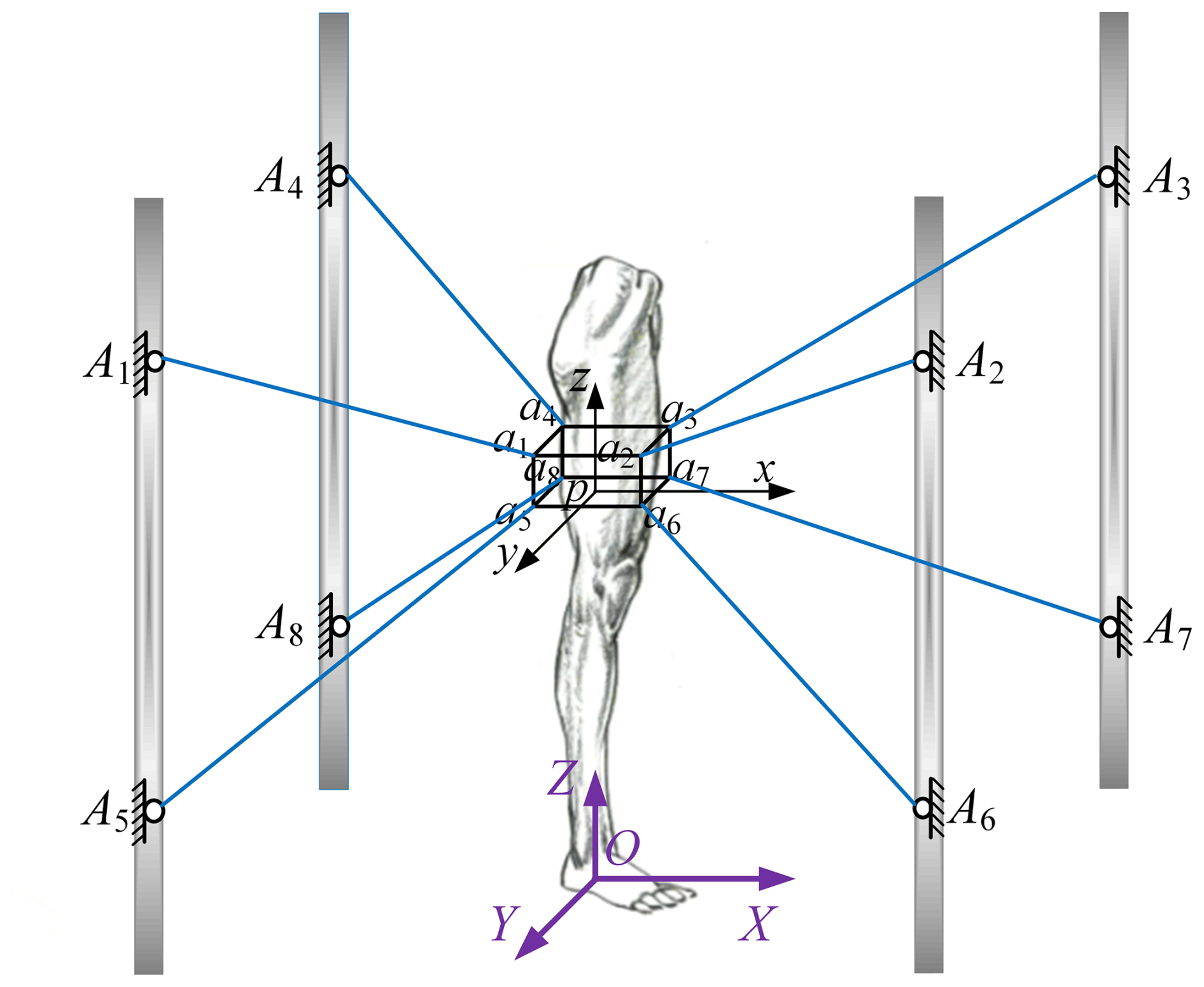
Regarding the cable connection points, let Ai (i=1, 2, …, 8) denote the fixed connection points of the ith cable with the fixed platform and ai (i=1, 2, …, 8) denote the connection points of the same cable with the moving platform. Meanwhile, to describe the geometric dimensions of the moving platform, parameters a, b, and c are introduced to represent the length, width, and height of the moving platform in the x, y, and z directions respectively.
In all subsequent kinematic derivations, it is assumed that the cables are always in a fully tensioned state, i.e., there is no slack or elastic elongation. Therefore, the elastic deformation, self-weight of the cables, and the sag effect caused thereby can be ignored, simplifying each cable into an ideal massless straight segment, which significantly reduces the modeling complexity. Meanwhile, in previous research (Qi et al., 2020), it was concluded that the degree of freedom of the skating training robot is 6. It can be seen that under the drive of eight cables, the moving platform can achieve rotation and translation in three-dimensional space, which can fulfill the training tasks of speed skaters.
3.1 Inverse kinematic analysis of the skating training robot
Inverse kinematics for the cable-driven skating training robot is defined as calculating the lengths of all driving cables given the predefined pose parameters of the end-effector (leg brace). The inverse kinematic model for this robotic system is depicted in Fig. 4a. For the cable-driven skating training robot, its end-effector (leg brace) acts as the movable platform of the overall robotic system, which is coupled with each pulley block module through driving cables with distinct lengths. In this configuration, Li (i=1, 2, …, 8) represents the length of the ith driving cable, and Ui stands for the unit vector corresponding to the length of the ith driving cable.
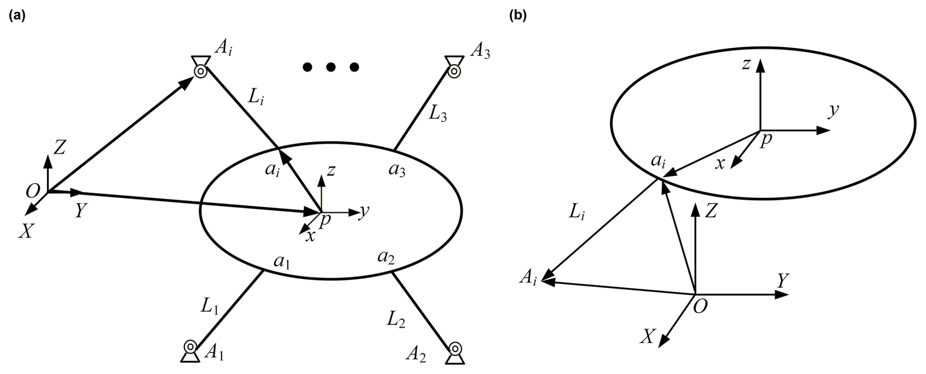
Figure 4Inverse kinematic model: (a) inverse kinematic model of the robot; (b) inverse kinematic model of a single cable.
For the skating training robot, inverse kinematics entails determining the length of each driving cable when the pose of the end-effector (leg brace) is known. The inverse kinematic model corresponding to this robotic system is presented in Fig. 4a. In this system, the end-effector (i.e., the leg brace) of the cable-driven ice-skating training robot acts as the moving platform. This moving platform is linked to each pulley block module via cables of differing lengths, where Li (for i=1, 2, …, 8) represents the length of the ith cable, and Ui denotes the unit vector corresponding to the ith cable.
Initially, the length characteristics of a single driving cable are analyzed for a predefined pose of the end-effector (leg brace). The inverse kinematic model corresponding to a single driving cable is depicted in Fig. 4b. Op designates the position vector of the local coordinate system's origin p with respect to the global coordinate system, while Opi denotes the position vector of the connection point ai within the local coordinate system. OAi signifies the position vector of the cable exit point Ai in the global coordinate system. Drawing on the coordinate system transformation relationship elaborated earlier, in conjunction with the closed vector quadrilateral approach, the length vector corresponding to a single driving cable can be deduced. The specific steps of this derivation process are presented as follows:
Here, R – rotation matrix from the fixed coordinate system to the moving coordinate system;
The length of the ith cable is expressed as follows:
where ∥⋅∥ denotes the norm. Subsequently, by substituting the position coordinates of specific points into Eq. (1), the length vectors of each individual cable can be derived.
3.2 Forward kinematic analysis of the ice-skating training robot
The importance of forward kinematic analysis for robotic systems resides in computing the positional and orientational parameters of the robot's end-effector based on prespecified joint parameters, a process vital for achieving accurate spatial localization and path formulation (Wang et al., 2025). The forward kinematic model characterizes the mapping correspondence between joint angular parameters and the positional and orientational states of the end-effector. By means of forward kinematic analysis, engineers are able to ascertain the precise positional coordinates and directional posture of the robot's end-effector under prespecified joint angular conditions (Huang et al., 2022; Luputi et al., 2022). For the cable-driven skating training robot, forward kinematic analysis is defined as calculating the solution for the positional posture of the moving platform within the fixed coordinate frame, given the known length parameters of each individual driving cable li (i=1, 2, …, 8). In this context, the resulting solutions include the positional coordinate s and attitude angles of the moving platform within this fixed coordinate frame.
It can be known from Eq. (2) that
The cable-driven skating training robot belongs to the category of parallel kinematic mechanisms. In the process of forward kinematic computation for cable-driven parallel kinematic mechanisms, the Newton–Raphson iterative method or analytical method are commonly employed as solution approaches. The analytical method entails a comparatively intricate procedure with large-scale computational workloads, placing stringent demands on computational capabilities. Serving as an approximate root-solving technique applicable to equations in both real and complex domains, the Newton–Raphson iterative method possesses prominent merits including rapid convergence speed and precise solution results. Consequently, the Newton–Raphson iterative method is adopted as the primary solution approach in the present research.
A construction function is established according to Eq. (3):
According to the Newton–Raphson iterative method,
where δXk denotes the pose increment of the moving platform:
where Fi(X) denotes the deviation function of the ith cable. Equation (6) is rearranged, and its specific form after rearrangement is given as follows:
where Ji represents the matrix obtained by taking the partial derivative of Fi(X) with respect to the pose. Its specific expression is given as follows:
Equation (8) is rewritten into its matrix form as follows:
where
The general formula for iterative solution is expressed as follows:
where J− denotes the pseudoinverse matrix of J. Its specific form is given as follows:
At the start of the iteration, the initial guess value is substituted in; its increment value δX0 is then calculated. The cyclic solution of Eq. (11) is performed until the constraint condition is satisfied, which represents the user-defined error limit. Regarding the convergence characteristics, the Newton–Raphson method exhibits quadratic convergence in the vicinity of the exact root, allowing it to reach high-precision targets within a minimal number of iterations. However, its convergence is inherently sensitive to the selection of the initial guess X0. To address this in practical engineering implementation, the kinematic pose of the moving platform from the previous control cycle is invariably selected as the initial guess for the current cycle. Given that the sampling period of the servo control system is at the millisecond level, the spatial displacement between adjacent cycles is infinitesimally small. This strategic selection perfectly satisfies the prerequisite that the initial value must be close to the exact solution, thereby strictly guaranteeing the robust convergence and real-time computational efficiency of the forward kinematic algorithm. Thus, the forward kinematic analysis of the ice-skating training robot is completed.
3.3 Forward and inverse kinematics simulation verification of the ice-skating training robot
To confirm the validity of the constructed forward and inverse kinematic analyses for the skating training robot, simulation verification of the forward and inverse kinematics was performed within the MATLAB platform.
Five sets of pose points were chosen to validate the forward and inverse kinematic algorithms. Initially, the five selected sets of pose points were fed into the system, and the lengths of the eight driving cables associated with each set of pose points were derived through inverse kinematic computation. Subsequently, the outcomes obtained from the inverse kinematic computation were entered, and the forward kinematic algorithm was employed to verify whether the output end-effector pose matched the five pre-chosen sets of pose points. The forward and inverse kinematic algorithms were considered valid provided that the deviation between these two sets of outcomes lied within a permissible range.
The five sets of pose points chosen within the workspace of the skating training robot are tabulated in Table 2.
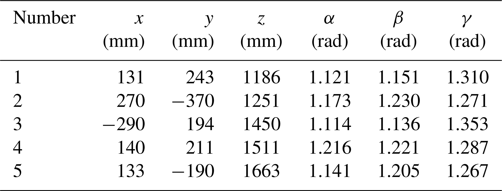
The coordinate values of the five sets of pose points listed in Table 2 were input into Eq. (2) in turn, and the lengths of the eight driving cables for the skating training robot associated with each individual set of pose points were derived through inverse kinematic calculation, with the resultant data tabulated in Table 3.
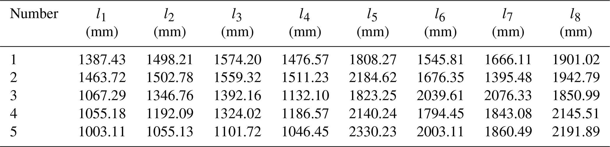
After the inverse kinematics solutions were obtained, these values were substituted into Eq. (11) for iteration, and the forward kinematics solutions were thus derived. The forward kinematics results are presented in Table 4.
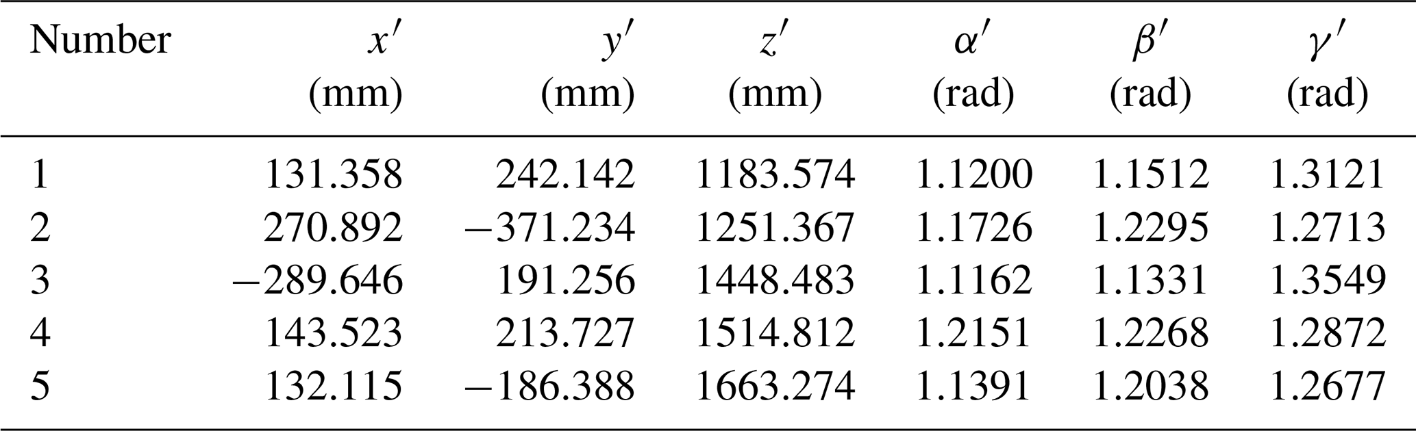
Having acquired the solutions to the forward kinematics problem, we present the error formula below, which is used to compute the deviations between the five sets of data in Tables 2 and 4.
where Y – xyzαβγ in Table 2; Y′ – in Table 4.
Following calculation and analysis, the maximum deviation of the five groups of experimental data is 0.95 %, a value lower than 1 %. This demonstrates that the average deviations of position and attitude for the five groups of pose points all lie within the permissible error margin, which can meet the demands of forward and inverse kinematic calculations. Therefore, the validity of the constructed kinematic model for the skating training robot is confirmed.
By means of the kinematic model and calculation for the skating training robot, the motion characteristics of the robotic system were elucidated, and precise control was achieved to guarantee the effectiveness and security of the training results. This, in turn, places strict demands on the anti-disturbance robustness and trajectory tracking precision of the control approach during the training process. To realize high-accuracy trajectory following and stable operation control of the skating training robot, as well as the accurate control and replication of athletes' skating motions, this research put forward a modified FOADRC method. Through the incorporation of fractional-order calculus operators to improve the structural design of the active disturbance rejection controller, the proposed method is intended to boost the trajectory tracking accuracy and dynamic response capability of the control system.
4.1 PMSM model
To ensure the stable operation of the permanent magnet synchronous motor (PMSM), a vector control method was adopted in this study. Based on the coordinate transformation theory of AC motors, the equivalent model of the PMSM was established using Park transformation and Clark transformation, resulting in control characteristics similar to those of DC motors. The stator voltage equations of the PMSM in the synchronous rotating coordinate system (d-q frame) are as follows:
where ud and uq are the d-q axis stator voltages, and id and iq are the d-q axis stator currents. R is the stator resistance, and Ld and Lq are the stator magnetic flux densities. ωe is the rotor electrical angular velocity, and ψf is the magnetic flux.
The electromagnetic torque of the PMSM in the d-q coordinate system can be expressed as follows (Roman et al., 2019):
To ensure the high reliability of the PMSM under harsh environments, a surface-mounted PMSM was selected in this study. A rotor flux-oriented control strategy (id=0) combined with a PI controller was adopted for the PMSM. When id=0 was substituted into Eq. (13), the stator voltage equation becomes
The electromagnetic torque equation is expressed as follows:
The expression of the q axis reference current given by the speed loop is
where Kpω and Kiω are the PI parameters of the speed loop, is the set speed of the PMSM, ωm is the mechanical angular velocity, and Bω is the active damping coefficient.
Based on the feedforward decoupling control strategy, the q axis voltage was obtained through the current loop:
The current and mechanical motion equations of the PMSM can be expressed as follows (Tom and Daya, 2025):
4.2 Fractional-order active disturbance rejection control strategy
By integrating the ADRC methodology with fractional-order control theory, the core principles of fractional-order algorithms were incorporated into the extended state observer module, enabling accurate estimation of both internal and external disturbances acting on the controlled system. Meanwhile, the nonlinear state feedback error control law was substituted with a fractional-order PID regulator. Through such a hybrid design, the resultant controller and its corresponding controlled plant exhibited prominent merits, including rapid dynamic response, strong anti-disturbance robustness, high control accuracy, and a broad parameter tuning range (Sangar et al., 2026).
Conventional ADRC architectures comprise a tracking differentiator component, whose primary role is to generate an optimized transient response profile and furnish the differential signal associated with this process. To prevent excessive overshoot during step signal responses, the control output magnitude is regulated to rise gradually at the initial phase of operation. Nevertheless, this conservative adjustment strategy inevitably leads to extended rise time and sluggish overall system responsiveness.
In light of the inherent structural features of the controlled object and the stringent requirements for high-speed control performance, the tracking differentiator was eliminated from the fractional-order ADRC controller proposed in this research. The core objective of this structural modification is to utilize the large initial error-derived control signal to drive the controlled system promptly, thereby realizing high-efficiency trajectory tracking capability of the control framework. On this basis, the FOADRC scheme developed in the present study is composed of two core modules, namely a fractional-order extended state observer and a fractional-order control law. The block diagram illustrating the system architecture is presented in Fig. 5.
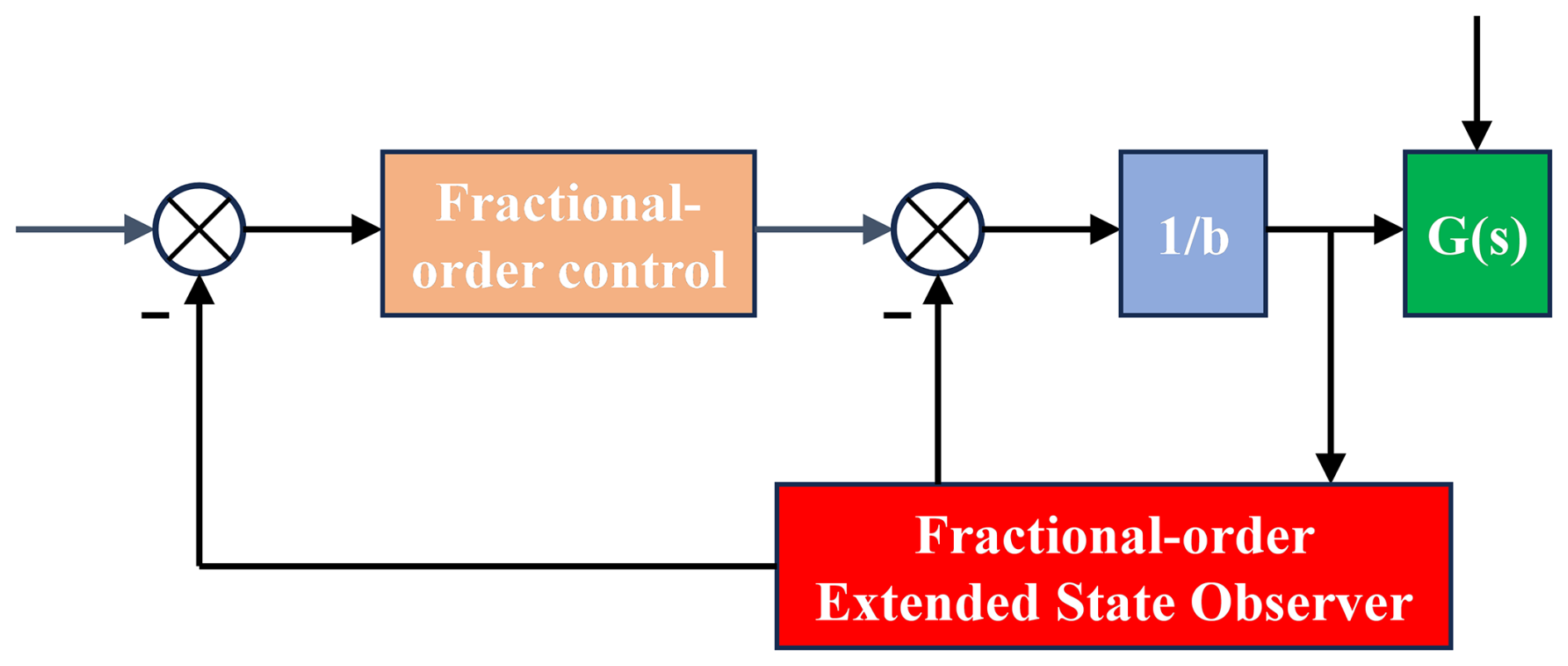
The application of fractional-order calculus in the active disturbance rejection controller is as follows:
where u represents the system input and y stands for the system output. α () designates the fractional-order differential order of the system. w denotes the external disturbance acting on the system, and b defined as the system gain parameter. a1 and a2 are the intrinsic parameter coefficients of the system.
Via a straightforward linear transformation approach, the fractional-order system can be equivalent to a second-order dynamic system. Thus, a third-order FOESO was adopted to precisely estimate the system states as well as internal and external disturbances, with the generated system errors compensated for by the fractional-order control law. By integrating the prominent superiorities of fractional-order controllers – including a broad parameter tuning range and excellent anti-disturbance robustness – with the core functional characteristic of active disturbance rejection controllers to real-time observe internal and external disturbances of the controlled system, the fractional-order active disturbance rejection controller was consequently developed and constructed.
4.3 Fractional-order extended state observer
As the core component of ADRC, the ESO is designed to estimate the internal and external disturbances acting on the controlled system. Drawing on the design principle of state observers, the disturbance factors that influence the system output are extended to form a new state variable; such an expansion process is independent of the disturbance generation model and enables the non-contact estimation of the system's disturbance signals without the need for direct detection. Firstly, Eq. (20) is rearranged and derived in the following form:
Taking the second-order position loop as the controlled object, it was expanded into a state space of the following form:
The total system disturbance is , with the specific expression , covering internal and external disturbances of the system. This disturbance was expanded into a state variable of the system, , where
According to the state space structure of the controlled object, a fractional-order extended state observer was designed as follows:
The outputs z1, z2, z3 of the observer observe the system states x1, x2, x3 respectively, and β1, β2, β3 are the gain coefficients of the extended state observer. The FOESO framework is shown in Fig. 6.
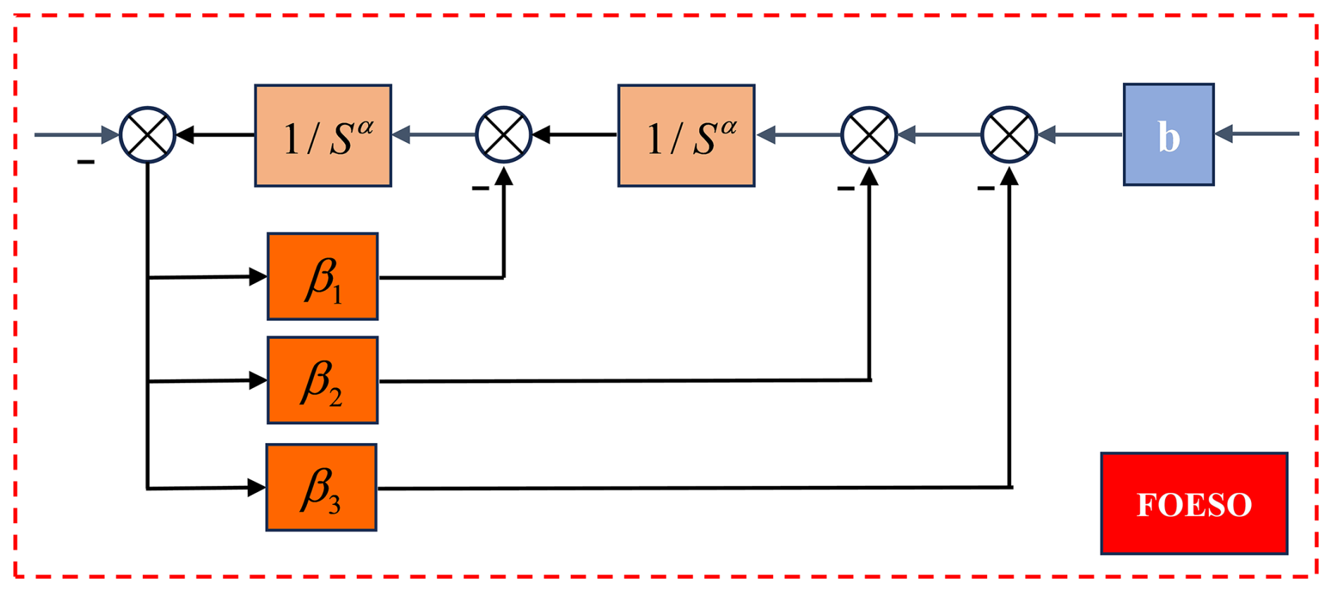
FOESO is a linear proportional fractional-order system; through the mapping relationship w=sα, where α is the proportional order of the original system, the complex plane of the proportional fractional-order system can be mapped to the complex plane of the integer-order system with w as the variable. Therefore, the stability of the fractional-order system can be analyzed by the root locus method:
By defining the error (i=1, 2, 3), the error equation of FOESO can be expressed as
After the w=sα mapping, the error equation becomes
Based on the bandwidth parameter tuning approach for integer-order extended state observers, to ensure the convergence of the error equation, the characteristic poles must be configured within the stable domain. Given that , it can be deduced that the root locus corresponding to its transfer function falls within the left half of the s-domain, namely that the stable domain encompasses the entire left half of the s-domain. This bandwidth-based tuning strategy for integer-order ESOs is thus applicable to the parameter calibration of linear fractional-order extended state observers (FOESOs). Hence, the design philosophy behind the bandwidth parameter method for integer-order ESOs is adopted for reference: all the aforementioned characteristic poles are set to be identical multiple roots, and the observer bandwidth concept put forward by Professor Gao Zhiqiang can be employed to characterize this configuration.
Therefore, the observer gain parameters are parameterized as β1=3w0, , . It can be seen that the only parameter to be adjusted is w0, which simplifies the parameter adjustment process of the fractional-order extended state observer.
4.4 Fractional-order calculus approximation method
Taking advantage of the modular independence of all components in ADRC, this research presents a fractional-order control unit to substitute for the state feedback error control law in the ADRC architecture. In contrast to conventional PID regulators, the FOPID controller introduces two additional tunable parameters, namely the integral order λ and the differential order μ. Consequently, the application of the FOPID controller in a control system enables it to deliver superior control performance characteristics. The structural block diagram of the FOPID controller is depicted in Fig. 7.
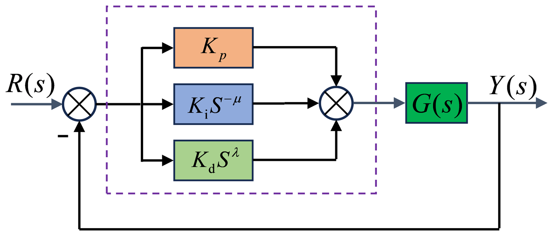
Since the disturbances in ADRC have been compensated and observed, the fractional-order PID (i.e., FOPID) control was adopted in this study (Li et al., 2022).
In regard to the fractional-order control scheme proposed in the present research, the Oustaloup method (Li et al., 2013a, b) was adopted to achieve the approximation of fractional-order differentiation. Firstly, the to-be-approximated frequency band [wb, wh] was defined and determined, and subsequently the corresponding rational approximation function was derived by means of rational function fitting, whose mathematical form is given as follows:
where
λ is the fractional order, and the order n in Eq. (31) is . Generally speaking, when n=5, the fitting result can meet the accuracy requirement (Chen et al., 2021)
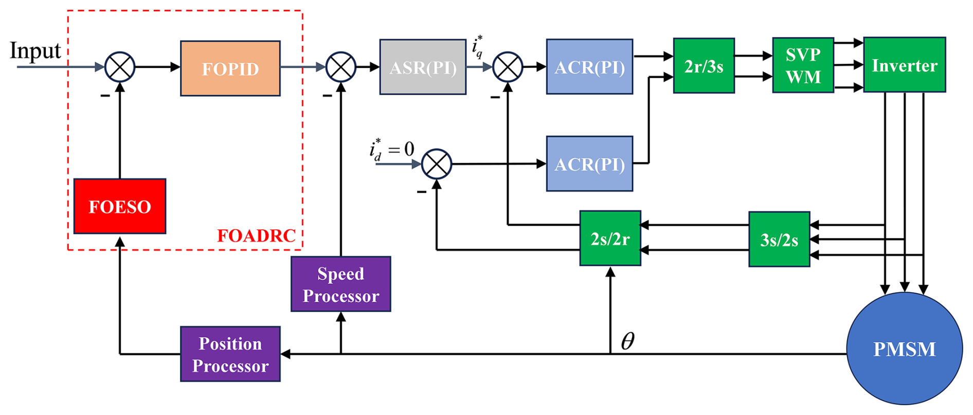
The FOADRC developed in the present research is to be implemented in the position loop within the control system. In line with the overshoot-free performance specification of the servo system, the developed fractional-order control law employs only fractional-order PD control. The structural block diagram of the position servo system is illustrated in Fig. 8.
5.1 Lower limb motion capture of the auxiliary training robot
To obtain the reference trajectory required for robot control, the NOKOV infrared motion capture system (configured with eight infrared cameras, capturing at a sampling frequency of 100 Hz with a spatial positioning error of less than 0.1 mm) was adopted to collect the lower limb motion data of the human body during skating. The experimental subject was a speed skater (male, 25 years old, height 178 cm, weight 70 kg), and the dynamic data during his standard straight-line skating cycle were continuously collected. The experimental process is shown in Fig. 9.
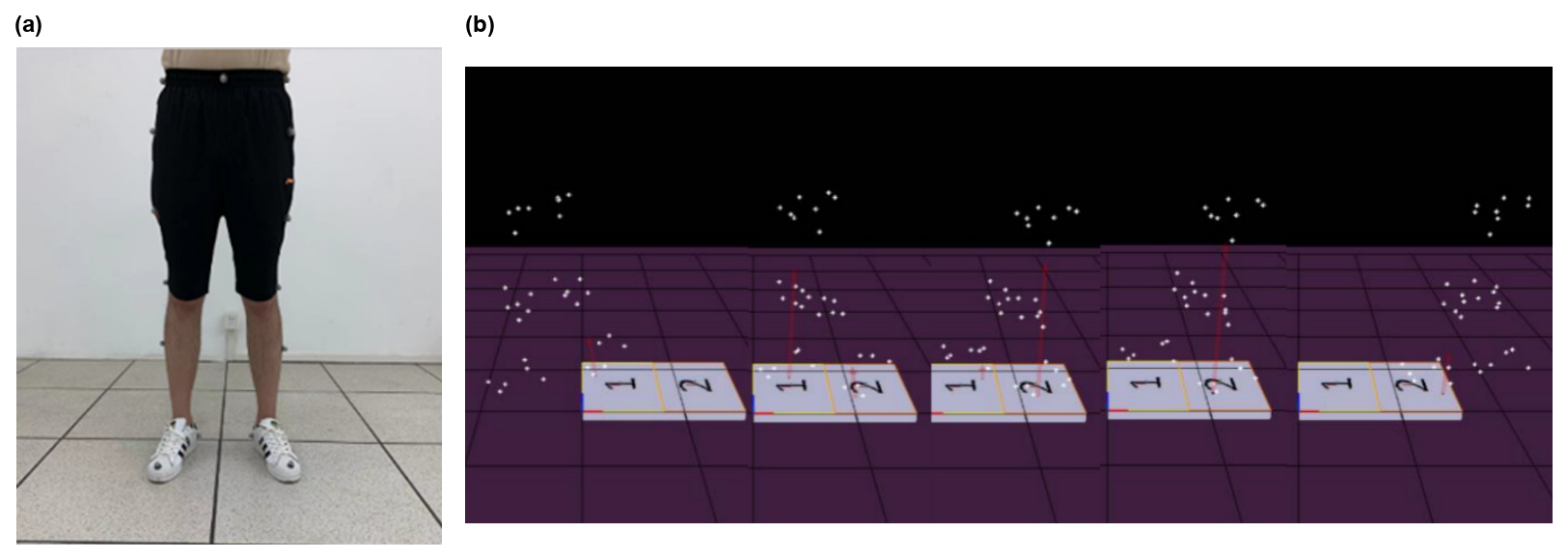
The hip joint is the connecting hub between the trunk and the lower limbs. During skating, the body weight of the human body must be transmitted to the lower limbs through the hip joint, which is a core supporting structure for maintaining an upright skating posture and stabilizing the body's center of gravity. During skating, the body's center of gravity shifts frequently, and the hip joint can adjust the position of the center of gravity by fine-tuning the angle (e.g., tilting, rotating) to maintain dynamic balance. Especially during high-speed skating and the post-push phase of speed skating, the load-bearing capacity of the hip joint directly determines the balance and stability of the body. This study focused on the movement of the hip joint in the coronal and sagittal planes.
Due to the limitations of the physiological structure of the human lower limb joints, the movement range of the core control joint (hip joint) was determined based on the physiological structure characteristics of the human lower limb joints: sagittal plane (flexion-extension) −50–40°, coronal plane (abduction/adduction) −40° (Baranowski et al., 2015). Retroreflective markers were attached to the key bony landmarks of the athlete's hip, thigh, lower leg, and ankle. After collecting the original motion data, noise reduction preprocessing was performed to extract the time series data, a fourth-order zero-phase Butterworth low-pass filter with a cutoff frequency of 6 Hz was applied to smooth the raw coordinates and eliminate high-frequency noise induced by soft tissue vibrations and environmental interference. Furthermore, a cubic spline interpolation algorithm was utilized to compensate for any missing data frames caused by momentary marker occlusions during high-speed motion. Following this rigorous noise reduction preprocessing, the kinematic model of the lower limb was processed to extract the precise time series data of hip joint angle and angular velocity.
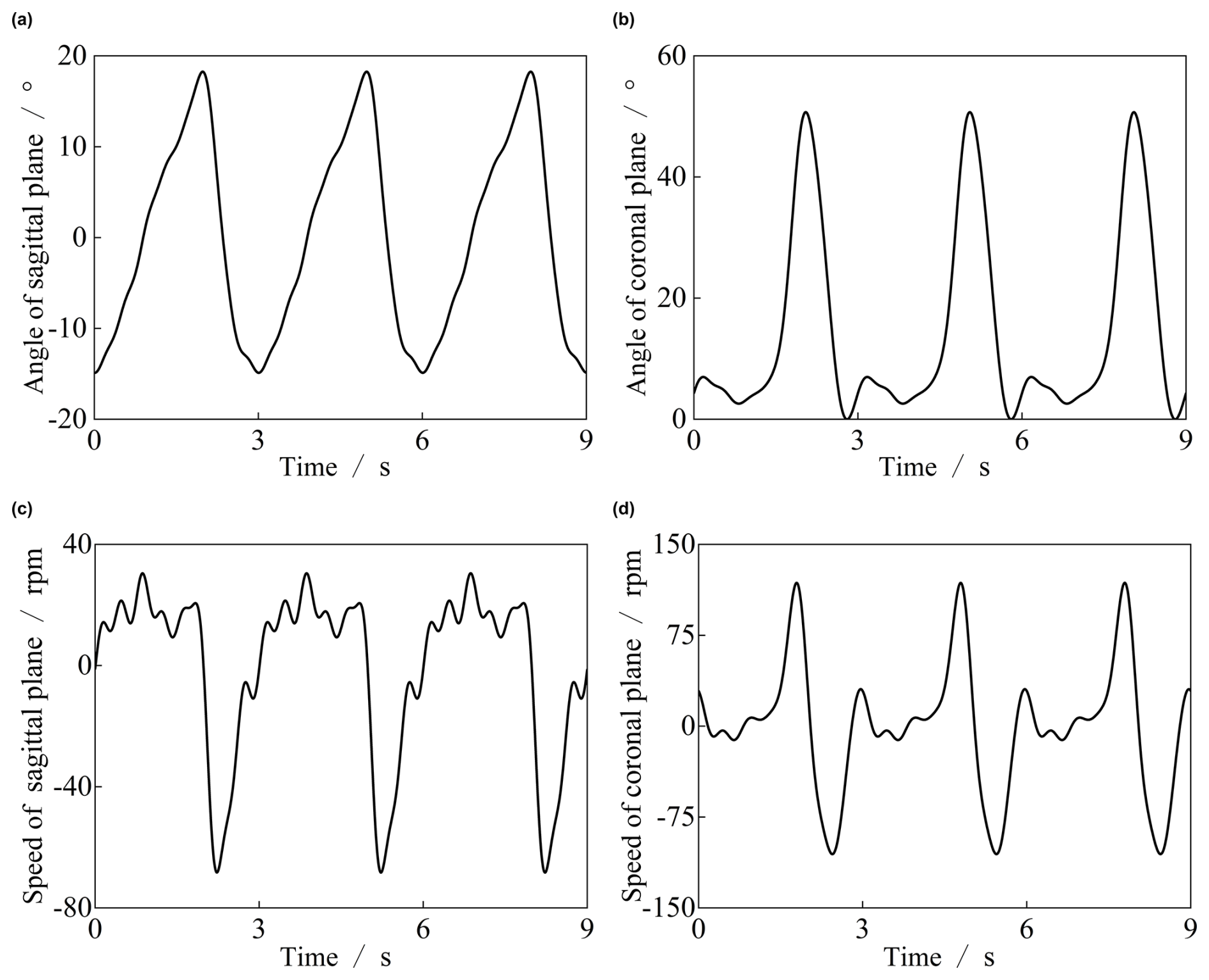
Figure 10Position and speed of the sagittal plane and coronal plane during skating: (a) angle of sagittal plane; (b) angle of coronal plane; (c) rotational speed of sagittal plane; (d) rotational speed of coronal plane.
First, by simulating human skating on the ground, the movement trajectories of various parts of the lower limbs during skating were obtained. The movement angles of the hip joint in space are shown in Fig. 10.
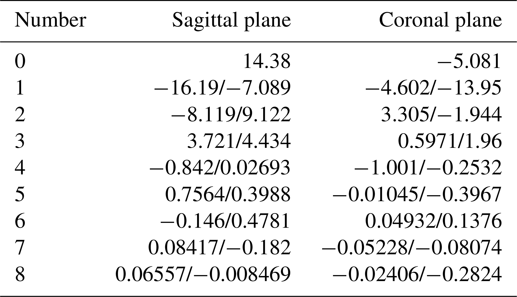
To obtain a smooth and reproducible control reference trajectory while ensuring the fitting accuracy of the Fourier series, an eighth-order Fourier series was employed to fit the preprocessed hip joint angle data. The coefficients corresponding to each order are shown in Table 5.
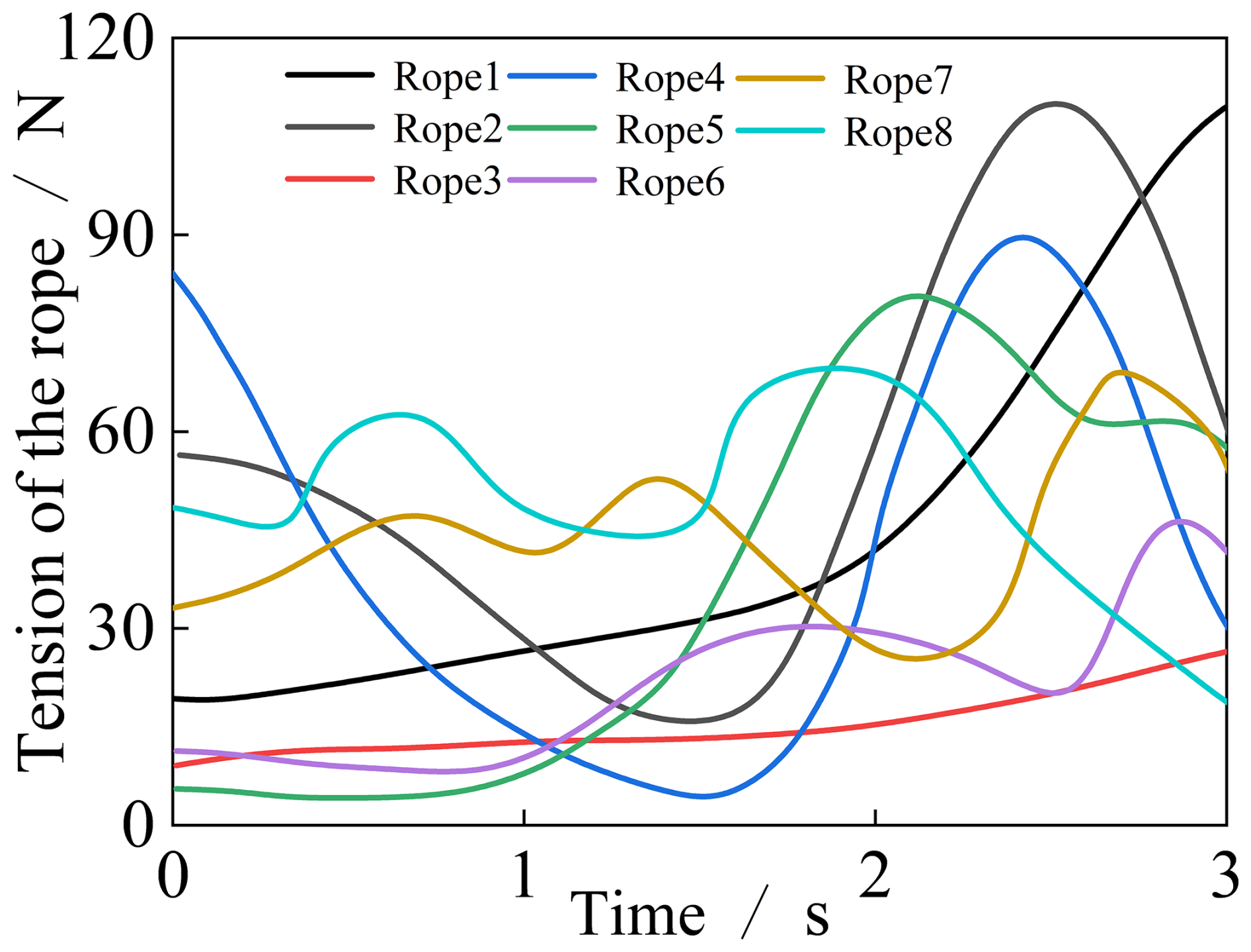
Since load magnitude is a critical factor affecting controller accuracy, the load torques of the eight cables governing hip joint movement were measured via sensors during the experiment. The specific magnitudes of cable tension are illustrated in Fig. 11. Collecting the tension values at corresponding positions through experiments to serve as the data source in subsequent control programs can render the control effect more consistent with practical scenarios.
5.2 Control system modeling and data required for input
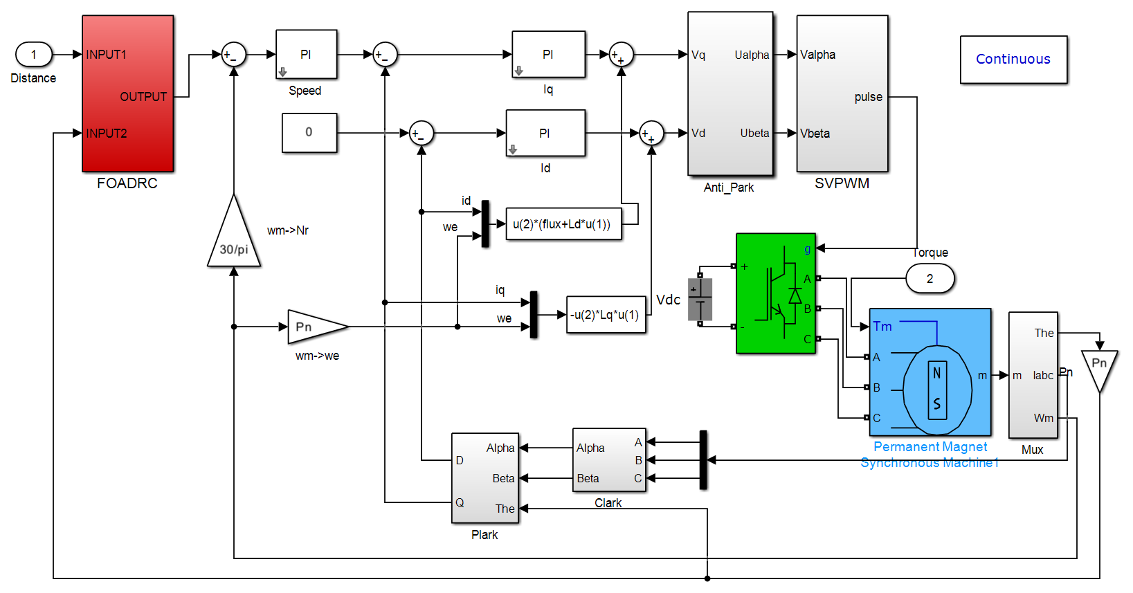
To verify the effectiveness and stability of the FOADRC method, conventional proportional-integral-derivative (PID) control was introduced as a benchmark method in this chapter. Specifically, trajectory tracking experiments on joint motion were conducted separately using these two control strategies, followed by a comparative analysis of their respective tracking performance. This experimental design aimed to verify whether the FOADRC method demonstrates superior control stability and trajectory tracking accuracy under actual skating conditions. A simulation structural model was established via Simulink, as depicted in Fig. 12.
Typically, the drive motors of robots are mounted at the joint positions of the mechanism. This mounting configuration increases the mass at the joints, thereby restricting the motion performance of the robot (Wang et al., 2021). Therefore, the drive motors of the cable-driven skating training robot are installed on the robot chassis, rendering the components directly attached to the human body more lightweight and further enhancing motion flexibility and skating training efficacy. The drive motors are connected to the ball screws via couplings, while the cables are attached to the sliders. When the motors rotate, they drive the ball screws to rotate, causing the sliders to move, which ultimately achieves the control of cable length variation and tension adjustment.
Based on the kinematic model established in Sect. 3, the fitted hip joint trajectory is converted into cable length variations, and then the ideal rotation angles and rotational speeds corresponding to each of the eight cables are solved. Regarding the accuracy and reliability of the solved ideal rotation angles, a detailed comparison of the solution algorithms has been conducted in Sect. 2, which will not be reiterated herein. Meanwhile, to fully verify the feasibility of the method proposed in this paper and avoid information redundancy, this chapter will present the control effects of Motors 1 and 2 corresponding to Cables 1 and 2.
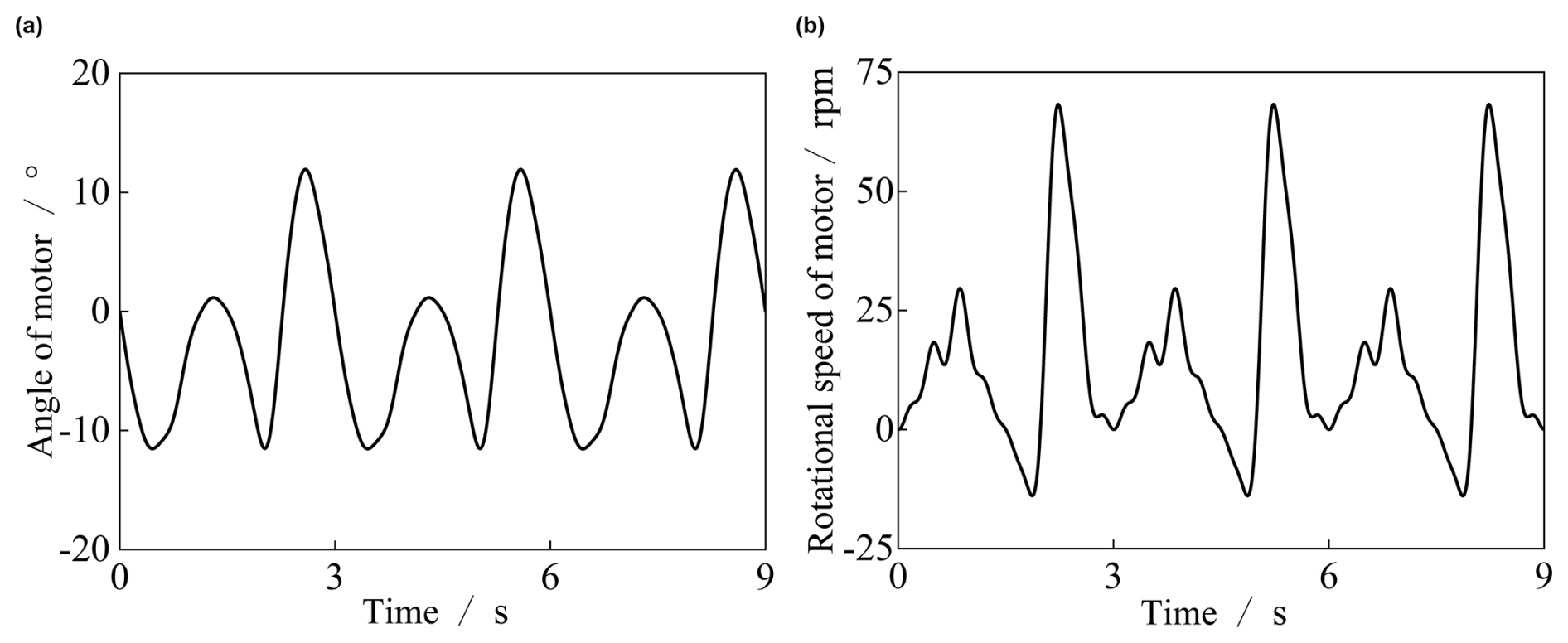
Figure 13Rotation angle and ideal speed of Motor 1: (a) angle of Motor 1; (b) rotational speed of Motor 1.
Taking the ideal rotation angles as the control targets of the method proposed in this paper, the required rotation angles and ideal rotational speeds of Motor 1 can be obtained through kinematic calculations, with the results illustrated in Fig. 13.
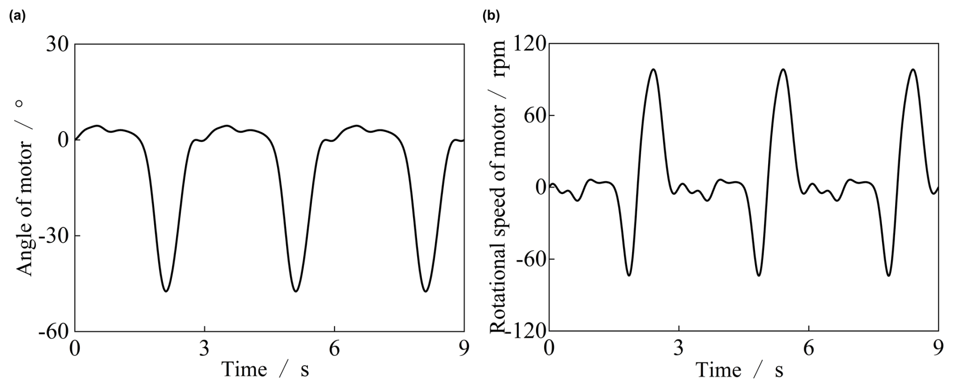
Figure 14Rotation angle and ideal speed of Motor 2: (a) angle of Motor 2; (b) rotational speed of Motor 2.
The required rotation angle and rotational speed of Motor 2 were derived through kinematic calculations, with the results presented in Fig. 14.
5.3 Result analysis
To verify the performance of the proposed improved fractional-order active disturbance rejection control (FOADRC), a comparative experiment with traditional PID control was conducted using the motor rotation angle tracking error as the evaluation index. The tracking error is defined as follows:
where θref(t) is the ideal rotation angle of the motor; θact(t) is the actual output rotation angle of the motor.
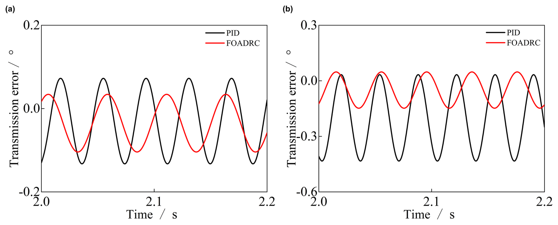
Figure 15Rotation angle and ideal speed of Motor 1 and Motor 2: (a) comparison of control effects of Motor 1; (b) comparison of control effects of Motor 2.
Taking the ideal rotation angles of Motor 1 and Motor 2 as position inputs, the transmission errors under the two control methods were derived respectively via Eq. (32). Figure 15 presents a comparison of the error results between the PID controller and the fractional-order active disturbance rejection controller (FOADRC). It can be clearly observed that, in contrast to the conventional PID control, FOADRC is capable of narrowing the error range and significantly improving the motion control accuracy. Furthermore, a comprehensive analysis of the control effects between Motor 1 and Motor 2 demonstrates a high degree of consistency in their tracking error profiles. Despite the distinct ideal motion trajectories and dynamic load variations experienced by different cables during the skating cycle, the FOADRC strategy maintains a stable, uniform, and low-error response across multiple drive units. This consistency is extremely critical for multi-motor cooperative control scenarios, as it ensures that all cables operate in precise synchronization without generating unbalanced internal tensions or uncoordinated mechanism movements. This finding fully validates the effectiveness, robustness, and superiority of the control method proposed in this study for complex multi-cable cooperative driving systems.
Addressing the high-precision trajectory tracking requirement of cable-driven skating training robots, this study conducted a full-process investigation encompassing mechanism design, kinematic modeling, and control strategy verification. Specifically, a cable-driven robotic mechanism tailored to skating scenarios was designed, and a geometric model of fixed-follower coordinate systems was established, laying a solid foundation for subsequent analyses. The forward and inverse kinematic equations were derived and solved using the Newton–Raphson iterative method; simulation results verified that the mapping error between the pose and cable length is ≤ 1 %, ensuring high model accuracy. An improved fractional-order active disturbance rejection control (FOADRC) strategy was proposed: by removing the tracking differentiator (TD) of traditional ADRC to accelerate dynamic response, and integrating a fractional-order extended state observer (FOESO) with a fractional-order PD control law, the strategy achieves effective compensation for internal and external disturbances and optimization of trajectory precision. Skating motion data were acquired via the NOKOV infrared motion capture system, and reference trajectories were generated through Fourier series fitting. Comparative simulation results demonstrate that the FOADRC strategy outperforms the traditional PID control significantly in both trajectory tracking accuracy and anti-disturbance performance. This study provides a practical and feasible technical solution for the intelligent and high-precision control of cable-driven skating training robots, and offers novel insights and references for the optimization of control strategies for similar intelligent auxiliary equipment in the field of competitive sports. However, this study is limited to simulation validation and single-subject data. Future work will construct a physical prototype and conduct multi-subject trials in real-world training scenarios.
The underlying research data are not publicly accessible. Access to the data may be granted upon reasonable request to the corresponding author, subject to approval.
BW conceptualized the study and acquired the funding and resources. XZ developed the methodology, wrote the original draft, and reviewed, validated, and edited the paper. YG analyzed the formula. LS curated the data. ZY visualized the data and developed the software.
The contact author has declared that none of the authors has any competing interests.
Publisher's note: Copernicus Publications remains neutral with regard to jurisdictional claims made in the text, published maps, institutional affiliations, or any other geographical representation in this paper. The authors bear the ultimate responsibility for providing appropriate place names. Views expressed in the text are those of the authors and do not necessarily reflect the views of the publisher.
We are grateful for the assistance and collaboration from our colleagues, which were essential to the success of this project. We also appreciate the research facilities provided by our institution and the constructive feedback from the reviewers.
This paper was edited by Zi Bin and reviewed by two anonymous referees.
Alwan, Y. H., Oglah, A. A., and Croock, M. S.: Optimized Adaptive Fuzzy Synergetic Controller for Suspended Cable-Driven Parallel Robots, Automation, 6, 15, https://doi.org/10.3390/automation6020015, 2025.
Baranowski, J., Bauer, W., Zagorowska, M., Dziwinski, T., and Piatek, P.: Time-domain Oustaloup approximation, 2015 20th International Conference on Methods and Models in Automation and Robotics (MMAR), 116–120, https://doi.org/10.1109/MMAR.2015.7283857, 2015.
Barnett, E., Boucher, G., and Gosselin, C.: Dynamic modeling, trajectory planning and prototyping of an ice-skating robot, Mechatronics, 94, 103008, https://doi.org/10.1016/j.mechatronics.2023.103008, 2023.
Buiter, S.: How syn-rift sedimentation promotes the formation of hyper-extended margins, EGU General Assembly 2020, Online, 4–8 May 2020, EGU2020-18622, https://doi.org/10.5194/egusphere-egu2020-18622, 2020.
Chen, P., Luo, Y., Zheng, W., Gao, Z., and Chen, Y.: Fractional order active disturbance rejection control with the idea of cascaded fractional order integrator equivalence, ISA Trans., 114, 359–369, https://doi.org/10.1016/j.isatra.2020.12.030, 2021.
Chen, Z., Liu, J., and Sun, M.: Overview of a novel control method: Active disturbance rejection control technology and its practical applications, CAAI Trans. Intell. Syst., 13, 865–877, https://doi.org/10.11992/tis.201711029, 2018.
Huang, Y., Lu, Q., Wang, H., Liu, J., Li, Z., Zou, X., and Zhan, X.: Kinematics Analysis and Simulation of a Novel 3T Parallel Mechanism, Math. Probl. Eng., 2022, 3424012, https://doi.org/10.1155/2022/3424012, 2022.
Iverach-Brereton, C., Baltes, J., Anderson, J., Winton, A., and Carrier, D.: Gait design for an ice skating humanoid robot, Robot. Auton. Syst., 62, 306–318, https://doi.org/10.1016/j.robot.2013.09.016, 2014.
Khan, M. I., Santamaria, V., Kang, J., Bradley, B. M., Dutkowsky, J. P., Gordon, A. M., and Agrawal, S. K.: Enhancing Seated Stability Using Trunk Support Trainer (TruST), IEEE Robot. Autom. Lett., 2, 1609–1616, https://doi.org/10.1109/LRA.2017.2678600, 2017.
Koukolová, I. L.: Overview of the Robotic Rehabilitation Systems for Lower Limb Rehabilitation, Transfer Inovácií, 31, 107–111, 2015.
Li, J. L., Bao, J. H., and Yu, Y.: Impedance Control System for a Biped Skating Robot, Appl. Mech. Mater., 475–476, 693–696, https://doi.org/10.4028/www.scientific.net/AMM.475-476.693, 2013a.
Li, M., Li, D., Wang, J., and Zhao, C.: Active disturbance rejection control for fractional-order system, ISA Trans., 52, 365–374, https://doi.org/10.1016/j.isatra.2013.01.001, 2013b.
Li, X. and Yao, Y.: Transmission characteristics analysis and friction compensation of double lasso driven upper limb rehabilitation robot, J. Mech. Sci. Technol., 39, 2211–2222, https://doi.org/10.1007/s12206-025-0342-y, 2025.
Li, Y.-X., Wei, M., and Tong, S.: Event-Triggered Adaptive Neural Control for Fractional-Order Nonlinear Systems Based on Finite-Time Scheme, IEEE Trans. Cybern., 52, 9481–9489, https://doi.org/10.1109/TCYB.2021.3056990, 2022.
Liu, C., Luo, G., Duan, X., Chen, Z., Zhang, Z., and Qiu, C.: Adaptive LADRC-Based Disturbance Rejection Method for Electromechanical Servo System, IEEE Trans. Ind. Appl., 56, 876–889, https://doi.org/10.1109/TIA.2019.2955664, 2020.
Lu, Y., Huang, A., Li, P., Wu, Q., and Liu, Y.: Robust adaptive nonsingular fast terminal sliding mode control for cable driven parallel robots, Proc. Inst. Mech. Eng. Part I J. Syst. Control Eng., 239, 841–855, https://doi.org/10.1177/09596518241301839, 2025.
Lu, Y., Zhang, F., Shang, W., Ma, Y., Gao, X., and Kong, L.: Design and modelling of a flexible cable-driven robotic joint with variable stiffness capability, Robot. Auton. Syst., 196, 105249, https://doi.org/10.1016/j.robot.2025.105249, 2026.
Luo, Y., Zhang, T., Lee, B. J., Kang, C., and Chen, Y. Q.: Fractional-Order Proportional Derivative Controller Synthesis and Implementation for Hard-Disk-Drive Servo System, IEEE Trans. Control Syst. Technol., 22, 281–289, https://doi.org/10.1109/TCST.2013.2239111, 2014.
Luputi, A.-M.-F., Lovasz, E.-C., Ceccarelli, M., Sticlaru, C., and Scurt, A.-M.: Kinematic study of feasibility of geared planar parallel manipulator, Proc. Inst. Mech. Eng. Part C J. Mech. Eng. Sci., 236, 10001–10016, https://doi.org/10.1177/09544062221105988, 2022.
Qi, Z., Zhang, W. L., Wang, M. Q., Liu, P. F., and Liu, Y. Q.: Study for the Application of Fractional Order PID Torque Control in Side-Drive Coupled Tram, Acta Autom. Sin., 46, 482–494, https://doi.org/10.16383/j.aas.c190084, 2020.
Roman, R.-C., Precup, R.-E., Petriu, E. M., and Dragan, F.: Combination of Data-Driven Active Disturbance Rejection and Takagi-Sugeno Fuzzy Control with Experimental Validation on Tower Crane Systems, Energies, 12, 1548, https://doi.org/10.3390/en12081548, 2019.
Sangar, B., Singh, M., and Sreejeth, M.: Enhancing PMSM Drive Performance for Electric Vehicles Through ANFIS-HCC Integration, Arab. J. Sci. Eng., 51, 7821–7834, https://doi.org/10.1007/s13369-025-10509-y, 2026.
Song, D., Lu, M., Zhao, L., Sun, Z., Wang, H., and Zhang, L.: A novel design method for a reconfigurable two-drive cable-driven parallel robot, Proc. Inst. Mech. Eng. Part C J. Mech. Eng. Sci., 239, 2049–2062, https://doi.org/10.1177/09544062241293253, 2025.
Tan, W. and Fu, C.: Linear Active Disturbance Rejection Control: Analysis and Tuning via IMC, IEEE Trans. Ind. Electron., 63, 2350–2359, https://doi.org/10.1109/TIE.2015.2505668, 2016.
Tom, A. M. and Daya, J. L. F.: Design of machine learning-based controllers for speed control of PMSM drive, Sci. Rep., 15, 17826, https://doi.org/10.1038/s41598-025-02396-y, 2025.
Wang, B., Shi, H., Shi, J., Zhao, X., Tong, T., and Wang, J.: Research on real-time kinematics algorithm and gait planning of rope-driven skating training robot, Arch. Mech. Eng., 765–793, https://doi.org/10.24425/ame.2025.155872, 2025.
Wang, Y., Lyu, C., and Liu, J.: Kinematic Analysis and Verification of a New 5-DOF Parallel Mechanism, Appl. Sci., 11, 8157, https://doi.org/10.3390/app11178157, 2021.
Yao, J. and Deng, W.: Active Disturbance Rejection Adaptive Control of Hydraulic Servo Systems, IEEE Trans. Ind. Electron., 64, 8023–8032, https://doi.org/10.1109/TIE.2017.2694382, 2017.
Zhang, L., Li, R., Ning, F., Chai, C., and Jia, Z.: Performance Analysis and Optimization Design of a Dual-Mode Reconfigurable Ankle Joint Parallel Rehabilitation Mechanism, Appl. Sci., 14, 1757, https://doi.org/10.3390/app14051757, 2024.
- Abstract
- Introduction
- Structure of the cable-driven skating training robot
- Kinematic model of the skating training robot
- Fractional-order ADRC control strategy for permanent magnet synchronous motors
- Experiments and verification
- Conclusion
- Data availability
- Author contributions
- Competing interests
- Disclaimer
- Acknowledgements
- Review statement
- References
- Abstract
- Introduction
- Structure of the cable-driven skating training robot
- Kinematic model of the skating training robot
- Fractional-order ADRC control strategy for permanent magnet synchronous motors
- Experiments and verification
- Conclusion
- Data availability
- Author contributions
- Competing interests
- Disclaimer
- Acknowledgements
- Review statement
- References