the Creative Commons Attribution 4.0 License.
the Creative Commons Attribution 4.0 License.
 | 06 Jul 2026
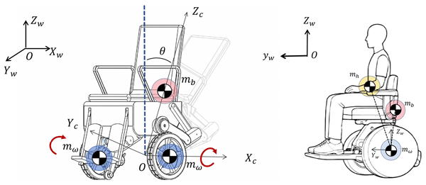
Hybrid nonlinear model predictive and linear quadratic balance control for a two-wheeled self-balancing wheelchair
Haomin Sun
Xinying Zhang
Yaozhi Gu
Shuai Wang
Weiyue Chen
Shuyue Zhang
Tianyu Xu
Hongliu Yu

A two-wheeled self-balancing wheelchair is a highly nonlinear and underactuated wheeled inverted-pendulum system, which faces severe balance control challenges under large tilt angles, load variations, and external disturbances. A hybrid nonlinear model predictive control–linear quadratic regulator (NMPC–LQR) balance control scheme is presented that combines nonlinear optimal recovery and efficient local stabilization while reducing the computational burden. A reduced-order nonlinear dynamic model of the wheelchair–occupant system is derived via the Lagrange method. The proposed controller confines LQR to a locally valid region verified by linearization-error analysis, whereas NMPC is employed for large-deviation recovery. A linearization-error analysis is first used to determine the switching-threshold search range, and a normalized five-index criterion identifies 0.100 rad as the optimal nominal threshold. Mass-sensitivity tests further provide an empirical relation for estimating the optimal threshold within the tested mass range. Comparative simulations under initial tilt angles of 35, 40, and 45° show faster convergence than standalone LQR and standalone NMPC controllers. Benchmark comparisons with SMC demonstrate a larger recoverable initial-angle range. Robustness tests under parameter variations, pulse and step disturbances, and flat-ground friction changes, together with prototype experiments, validate the stability, disturbance rejection, and engineering applicability of the proposed control strategy.
- Article
(5243 KB) - Full-text XML
- BibTeX
- EndNote


Two-wheeled self-balancing wheelchairs are becoming increasingly popular due to their compact structure, greater maneuverability in narrow spaces, and better adaptability to complex indoor and outdoor environments (Zhang et al., 2024). They represent a promising solution for improving the mobility of individuals with lower-limb impairment during daily living. However, such wheelchairs must not only provide mobility but also ensure stability and safety under various operating conditions to be truly useful and acceptable (Onozuka et al., 2020). Consequently, stability and safety have become the two key concerns for both researchers and users. The inherent static instability of self-balancing wheelchairs necessitates high gain feedback of fast state estimation, which inevitably amplifies sensor noise and model errors. Kalman filtering has been widely adopted to mitigate this sensitivity, as demonstrated by Huynh et al. (2017) in an optimal control framework, by Zhang et al. (2019) within a PID structure, and by Ma et al. (2024) using a fuzzy Kalman approach. However, these methods share three critical weaknesses: (i) reliance on known model and noise statistics, which do not hold under load variations; (ii) heuristic parameter tuning without online adaptation; and (iii) a decoupled design of estimation and control, leading to degraded performance under large-angle deviations or external disturbances. Thus, developing an adaptive or robust co-design of state estimation and feedback control remains an open challenge.
Model-based controllers have been explored to overcome the poor adaptability existing in conventional methods. Among them, the LQR controller has been widely used in self-balancing systems due to its simple structure and satisfactory local stabilization performance. For instance, Feng et al. (2023) applied LQR to a two-wheel-legged robot and verified its efficient and stable regulation capability near the equilibrium point. Owing to its linear nature, LQR performs well near the equilibrium point but deteriorates rapidly under large-angle deviations. Recent studies have attempted to improve the robustness of LQR by introducing online self-tuning or hierarchical reconfiguration mechanisms. For example, Saleem et al. (2021) proposed several hierarchical self-tuning LQR procedures in which the weighting factors of the quadratic performance index are adjusted online to improve disturbance rejection in under-actuated mechatronic systems. Even with friction feedforward compensation (Zhang et al., 2025), its effective operating region remains fundamentally constrained. Compared with regular self-balancing vehicles, self-balancing wheelchairs are characterized by larger-scale and higher inertia, making safety an overriding concern in control design. Under sudden external disturbances, the system must be stabilized rapidly to avoid overturning while maintaining acceptable recovery performance even at relatively large inclination angles. This inevitably leads to strongly nonlinear dynamic behavior. Analogous control difficulties have been observed in two-wheeled inverted-pendulum systems subject to uncertain rolling resistance and angle limits (Liang et al., 2021). Consequently, the sole use of LQR control is insufficient to achieve satisfactory performance for self-balancing wheelchairs. Hence, the design of advanced control schemes capable of dealing with severe system nonlinearity still poses a considerable challenge.
Predictive, adaptive, and intelligent control approaches have attracted increasing attention to cope with nonlinear behavior during large-angle recovery (Zhang and Mohamad Nor, 2025). For instance, Cui et al. (2015) and Li and Zhang (2010) employed adaptive backstepping and motion/force control strategies, respectively, for wheeled inverted-pendulum systems. Shen and Hong (2022) proposed an MPC strategy for a two-wheeled inverted-pendulum system and demonstrated its capability to handle nonlinear effects through online control. However, its effectiveness under strongly nonlinear large-angle recovery conditions remains insufficiently validated. Liu et al. (2024) introduced NMPC into the control of a self-balancing wheelchair to further improve control performance under highly nonlinear conditions, while Li et al. (2021) demonstrated the applicability of predictive control to nonholonomic wheel-legged robots. These results indicate that predictive control methods are effective in handling nonlinear system dynamics. Nevertheless, it is important to emphasize that model predictive controllers still rely on online optimization at each sampling instant, thereby imposing a substantial computational burden. In addition, the control effectiveness in the near-equilibrium region is not always superior to that of traditional control approaches. An NMPC–LQR hybrid controller is proposed to improve large-angle recovery while reducing the computational burden. When the self-balancing system experiences a relatively large tilt angle, the NMPC controller is activated to provide the control input. As the tilt angle decreases and enters a predefined threshold region, the control law is switched to the LQR controller. The proposed strategy therefore combines the nonlinear recovery capability of NMPC under large-tilt-angle conditions with the computational efficiency and regulation performance of LQR in the near-equilibrium region. Furthermore, a switching-threshold evaluation method is also designed to resolve the problem of switching-angle selection. Subsequent simulations and experiments verify the effectiveness and practical applicability of the proposed hybrid controller for engineering implementation.
The main contributions are summarized as follows:
-
A reduced-order wheelchair–occupant dynamic model is established for longitudinal balance recovery, and the validity range of the modeling assumptions is explicitly discussed.
-
A hybrid NMPC–LQR balance controller is constructed, where NMPC is used for large-deviation nonlinear recovery and LQR is restricted to the local region supported by linearization-validity analysis.
-
A switching-threshold selection procedure is developed by combining linearization-error analysis and a normalized five-index evaluation criterion. In addition, a mass-sensitivity study is conducted to obtain an empirical threshold-estimation relation within the tested equivalent-mass range.
-
Comparative simulations, SMC benchmark tests, disturbance tests, friction-coefficient tests, computational-efficiency tests, and prototype experiments are conducted to evaluate the proposed method.
However, three gaps remain:
-
switching thresholds in existing hybrid schemes are often selected empirically, and their searchable range or parameter-dependent estimation is rarely quantified;
-
the validity range of LQR linearization is rarely quantified when large initial tilt angles are considered;
-
limited studies validate wheelchair-oriented hybrid control under load variations, friction mismatch, external disturbances, and prototype experiments.
The remainder of this paper is organized as follows. Section 2 presents the reduced-order dynamic model of the wheelchair–occupant system and discusses the validity range of the modeling assumptions. Section 3 introduces the hybrid NMPC–LQR controller, the linearization-error-based threshold search range, the five-index threshold evaluation method, the mass-dependent threshold estimation, and the stability considerations. Section 4 reports comparative simulations, SMC benchmark tests, pulse- and step-disturbance tests, friction-coefficient tests, computational-efficiency evaluations, and prototype experiments. Section 5 concludes the paper and discusses the limitations and future research directions.
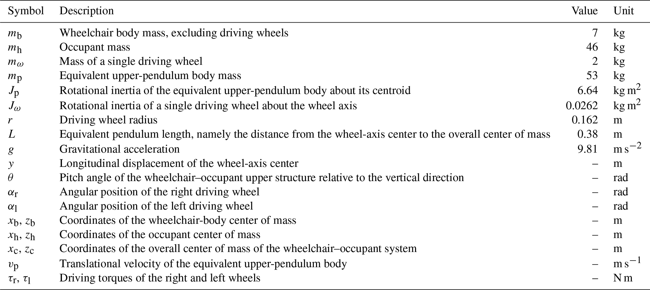
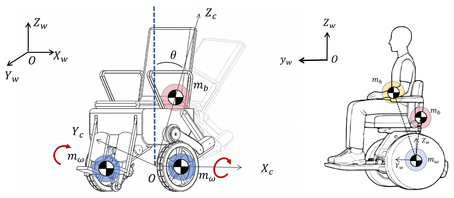
Since both LQR and NMPC are model-based control methods, the accuracy of the dynamic model is of great importance. The wheelchair system is simplified as an inverted-pendulum system, following the classical modeling framework commonly adopted for nonholonomic two-wheeled inverted-pendulum robots (Kim et al., 2005). The main symbols and physical parameters used in the dynamic model are summarized in Table 1. The three-dimensional wheelchair–occupant configuration and the planar reduced model used in the subsequent derivation are shown in Fig. 1.
Table 1Main symbols and physical parameters of the wheelchair–occupant system.
The following assumptions are adopted:
-
Item 1. Only the motion of the wheelchair system in the longitudinal plane is considered, while yaw, roll, and left–right asymmetry are neglected.
-
Item 2. The two driving wheels are assumed to have identical structural and inertial parameters.
-
Item 3. Pure rolling without slipping is assumed between the driving wheels and the ground.
-
Item 4. The relative posture between the wheelchair body and the occupant is assumed unchanged and is treated as a rigidly connected whole.
-
Item 5. The effects of tire elastic deformation and local ground unevenness are neglected.
The above assumptions are adopted to obtain a tractable reduced-order model for real-time controller design. Therefore, the proposed model mainly describes longitudinal balance recovery and pitch stabilization during straight-line motion. Yaw, roll, lateral motion, tire deformation, wheel slip, and active occupant motion are not explicitly considered. The rigid-body assumption between the wheelchair and the occupant is reasonable when the occupant maintains a relatively fixed seated posture, but it may introduce modeling errors when the occupant posture or mass distribution changes. In addition, friction and external forces are not included in the nominal prediction model but are treated as unmodeled dynamics and external disturbances. Their influence is further evaluated through parameter-variation and disturbance-rejection simulations.
The two driving wheels are connected by a light linkage, and the total mass of the system is represented by an equivalent concentrated mass. This equivalent mass is connected to the midpoint of the two wheels. These uncertainties are further investigated in the robustness tests (Dai et al., 2015).
2.1 Determination of the overall center of mass
The equivalent pendulum-body mass of the upper structure is defined as
The total mass of the system consists of the wheelchair body, excluding the two driving wheels, and the occupant mass. The overall center of mass of the wheelchair–occupant system is determined by mass-weighted averaging:
where (xb,zb) and (xh,zh) denote the center-of-mass coordinates of the wheelchair body and the occupant, respectively, and (xc,zc) denotes the overall center-of-mass coordinates of the wheelchair–occupant system.
2.2 Unconstrained dynamic modeling
The total kinetic energy of the system consists of the translational and rotational kinetic energy of the equivalent upper body Tp and the two driving wheels Tω:
where vp is the translational velocity of the equivalent upper-pendulum body, and denotes the common angular velocity of the two driving wheels under straight-line motion, namely . The potential energy is determined mainly by the gravitational position of the equivalent upper body:
and the Lagrangian is
Substituting the above expressions into the Lagrange equations yields
where is the generalized coordinate vector, and 𝒬 denotes the generalized force vector. For convenience in subsequent analysis, the unconstrained nonlinear dynamics can be written in the compact form
where u denotes the single-wheel driving torque under symmetric actuation, with . Therefore, the total longitudinal driving force generated by the two wheels is . Ac(q) is the nonholonomic constraint matrix, Bd(q) is the dynamic input matrix, and λ denotes the Lagrange multipliers associated with the wheel–ground motion constraints.
2.3 Nonholonomic constraint equations and model reduction
Due to the pure rolling assumption of the two driving wheels, the wheel–ground motion constraints can be written as
where y denotes the longitudinal displacement of the wheelchair body; r is the wheel radius; and αr and αl are the angular displacements of the right and left wheels, respectively.
Taking the time derivative of Eq. (9), the velocity-level nonholonomic constraints are obtained as
Let the full generalized coordinate vector be defined as
Then Eq. (10) can be expressed in matrix form as
where the constraint Jacobian is
Before eliminating the constraint forces, the constrained Lagrange equations can generally be written as
where Mf(q) is the full mass matrix, denotes the Coriolis and centrifugal terms, Gf(q) is the gravitational term, and Bf(q) is the full input distribution matrix. The input u denotes the single-wheel driving torque under symmetric actuation, namely , and λ is the vector of Lagrange multipliers associated with the rolling constraints.
To avoid explicitly solving the constraint reaction forces in the control model, a null-space projection method is employed. The following derivation gives the projection procedure used to eliminate the Lagrange multipliers and obtain the reduced-order dynamics. Let S(q) be a basis matrix of the null space of Ac(q), satisfying
For straight-line symmetric motion, the independent velocity vector is selected as
The full generalized velocity can then be parameterized as
where
It can be verified from Eqs. (13) and (18) that
which indicates that all generalized velocities generated by S(q)v automatically satisfy the nonholonomic rolling constraints.
Taking the time derivative of Eq. (17) gives
Substituting Eqs. (17) and (20) into Eq. (14) yields
Premultiplying both sides of Eq. (21) by ST(q) gives
According to Eq. (15),
Therefore, the term containing the Lagrange multipliers is eliminated by the null-space projection, and the reduced-order dynamic model can be written as
where
Since S(q) in Eq. (18) is constant for the present longitudinal rolling model, .
For the reduced longitudinal balance model, Eq. (24) can be further expressed as
where
The reduced matrices are given by
Here, mp denotes the equivalent mass of the wheelchair–occupant body, mω denotes the mass of a single wheel, Jω is the wheel moment of inertia, Jp is the pitch moment of inertia of the wheelchair–occupant body, L is the distance from the wheel axle to the equivalent center of mass, and g is the gravitational acceleration.
For numerical implementation in the NMPC prediction model and Simulink simulation, Eq. (26) is solved explicitly as
Let
Then the longitudinal acceleration and pitch angular acceleration are obtained as
For the balance control problem, the state vector is selected as
The nonlinear state-space model used in the controller design is then written as
3.1 Overall construction of the control method
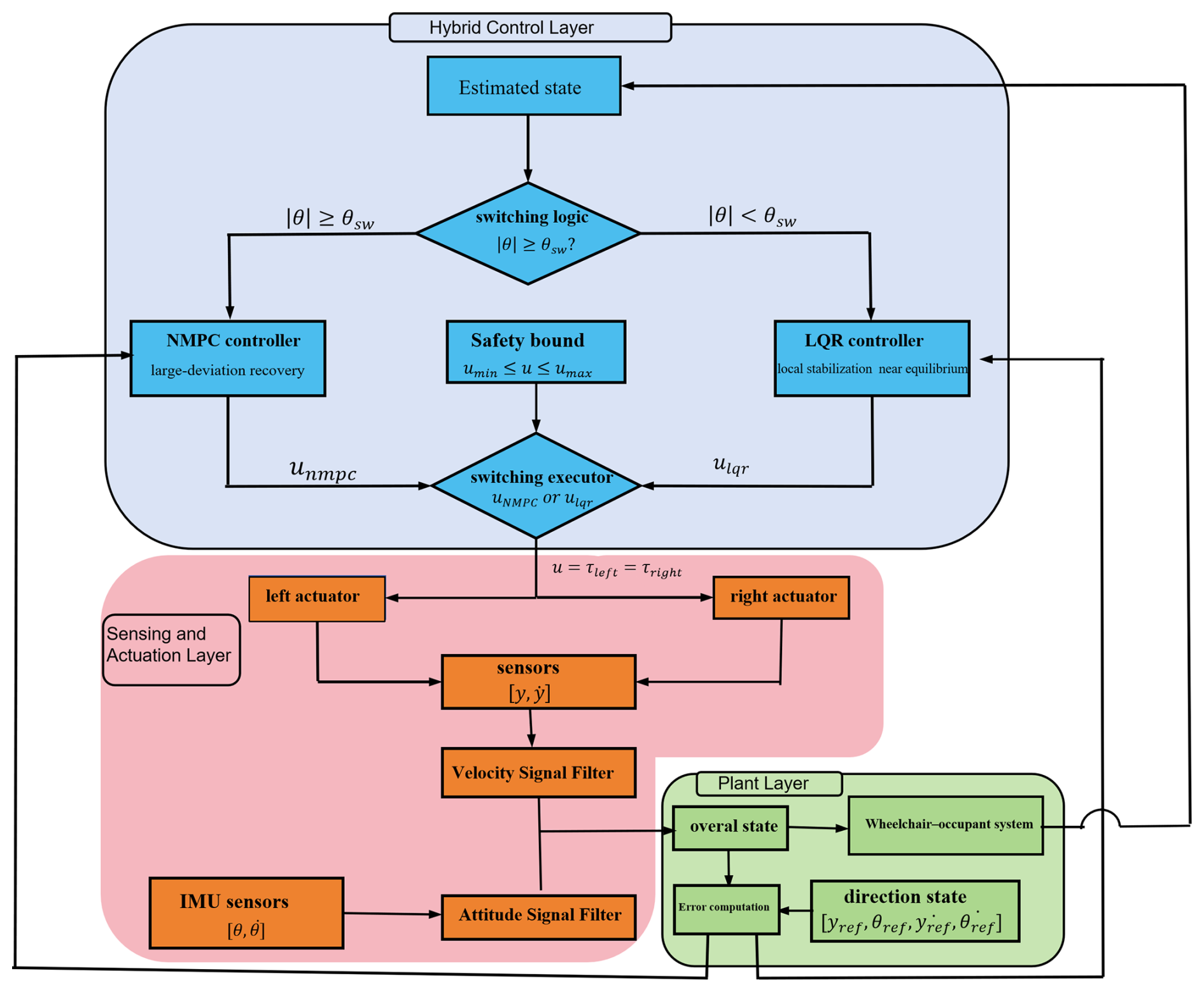
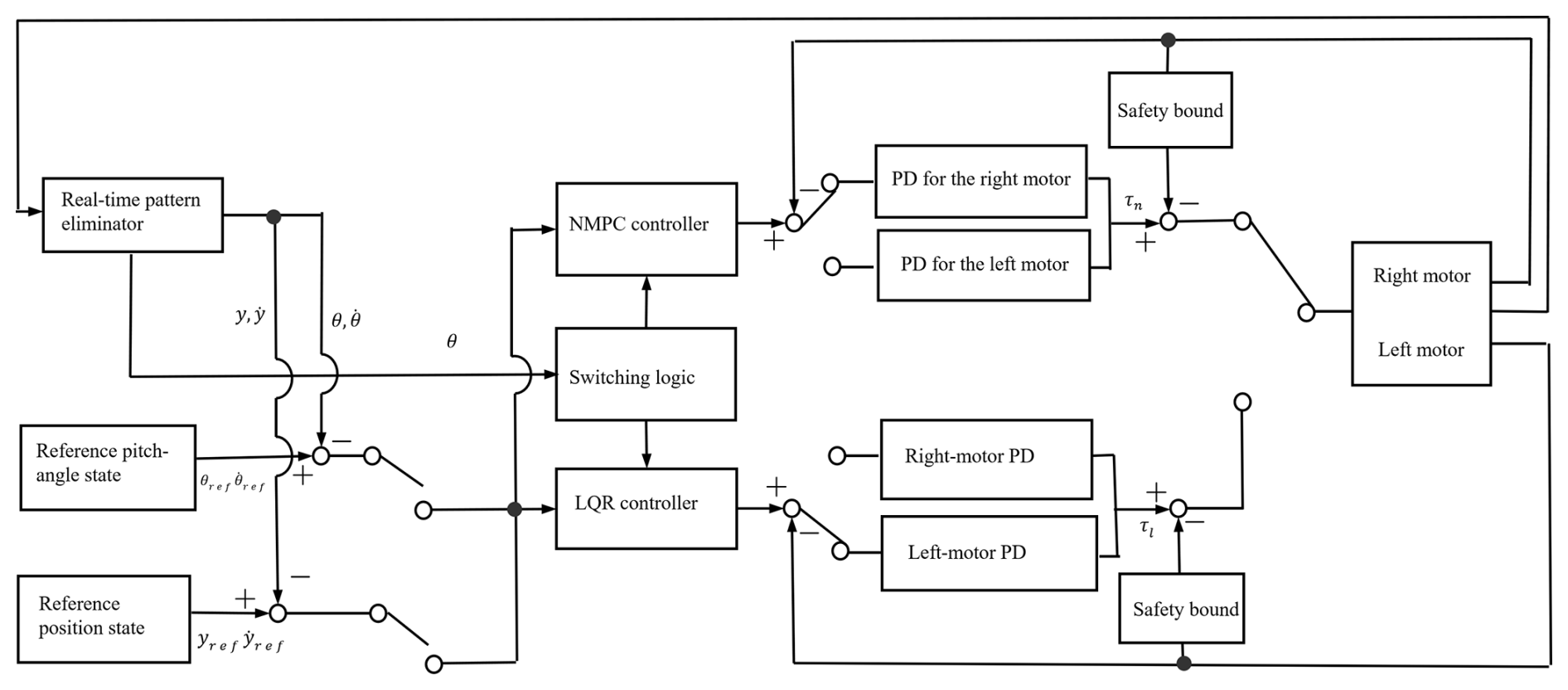
The hybrid controller is designed to address the online optimization problem in self-balancing control. The controller provides the driving torque command to the PD-actuated system. It consists of two components, namely an NMPC controller and an LQR controller. When the tilt angle exceeds the predefined switching threshold θsw, the NMPC controller is activated to cope with the nonlinear operating condition. In the controller design, u denotes the single-wheel torque command, and the same command is applied to the left and right wheels under straight-line symmetric motion. Once the tilt angle falls below the switching threshold, the control law is switched to the LQR controller:
The overall hybrid control architecture is illustrated in Fig. 2.
3.2 LQR controller design
The LQR controller is used for local stabilization when the system approaches the equilibrium point. Based on the linearized state-space model and with reference to Chacko and Abraham (2023), the cost function of the LQR controller is constructed as
where QL and RL are the weighting matrices for the state error and the control input, respectively. They are selected as
By solving the algebraic Riccati equation, the optimal feedback gain matrix is obtained, and the LQR control law becomes
where K is the LQR feedback gain matrix and xref denotes the reference state vector.
3.3 NMPC controller design
The NMPC controller is employed to address the highly nonlinear behavior of the system. When the tilt angle of the wheelchair exceeds the switching threshold, the NMPC controller is activated. At each control update, an optimal control sequence over a finite prediction horizon is solved online on the basis of the current system state and the nonlinear dynamic model. Only the first control input is then applied to the system, thereby forming a receding-horizon optimization framework.
With the state at the kth sampling instant, prediction horizon Np, and sampling time defined, the finite-horizon objective function is written as
where k is the current sampling instant, i is the prediction-step index, Np is the prediction horizon, and uk+i is the predicted equivalent torque input at the (k+i)th step. The weighting matrices are selected by prioritizing attitude safety. Larger weights are assigned to the pitch angle and pitch angular velocity, while the input term penalizes excessive wheel torque:
The nonlinear state equations are directly used as prediction-model constraints, and actuator limits are imposed as input constraints:
Here, umin and umax are the lower and upper bounds of the single-wheel torque command.
3.4 Switching-threshold evaluation and parameter sensitivity
The switching threshold determines the boundary between the nonlinear recovery stage and the local stabilization stage. According to the switching law in Eq. (34), NMPC is activated when , whereas LQR is used when . Therefore, if the threshold is too small, the NMPC controller remains active until the system is very close to the equilibrium, which increases the computational burden and may delay the use of efficient local regulation. Conversely, if the threshold is too large, the controller may switch to LQR while the system is still in a region with strong nonlinear effects, which may weaken the recovery capability and reduce the validity of the local linear controller. Hence, the switching threshold must be selected by considering both nonlinear recovery and local stabilization performance.
3.4.1 Determination of the threshold search range
Before evaluating the switching threshold, a linearization-error analysis was conducted to determine a reasonable search interval. The nonlinear model and the linearized model were compared under different local angular ranges. The tested ranges were selected as 0.015, 0.030, 0.050, 0.080, 0.100, and 0.150 rad, which correspond to the candidate switching thresholds used in the following evaluation. An additional range of 0.200 rad was included as an outside reference.
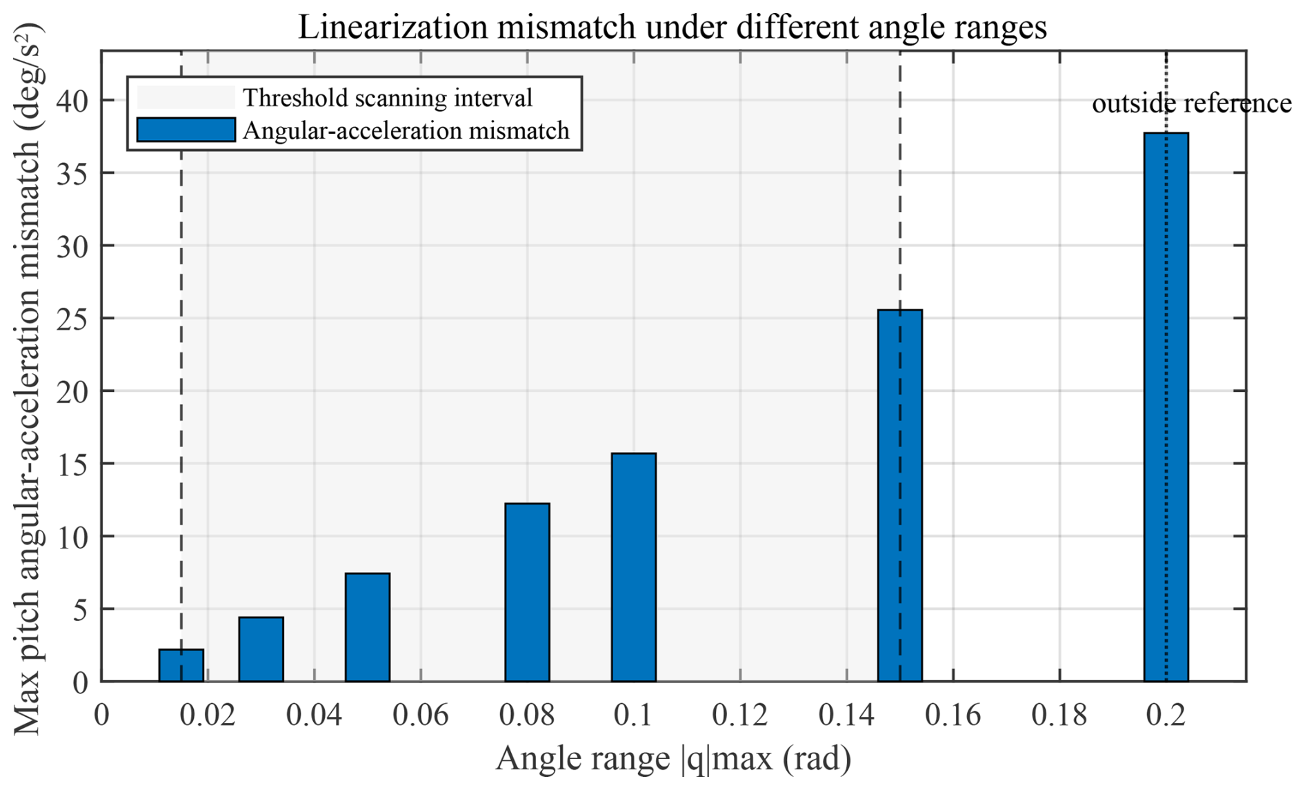
Figure 3Linearization mismatch under different angular ranges. The shaded region denotes the selected switching-threshold search interval of 0.015–0.150 rad, while 0.200 rad is used as an outside reference.
The results in Fig. 3 show that the pitch angular–acceleration mismatch increases as the angular range expands. Within the interval of 0.015–0.150 rad, the mismatch increases gradually, whereas a more pronounced increase is observed when the range is enlarged to 0.200 rad. Therefore, the interval of 0.015–0.150 rad is adopted as the switching-threshold search range. It should be noted that the linearization-error analysis is used to determine the candidate range, while the final threshold is selected according to the five-index performance evaluation.
3.4.2 Five-index evaluation under nominal parameters
Based on the above search interval, six switching thresholds are selected for simulation tests:
Under identical initial conditions, controller parameters, and input constraints, the five performance indices corresponding to each threshold are extracted, as shown in Table 2.
Table 2Performance indices under different switching thresholds under nominal model parameters.
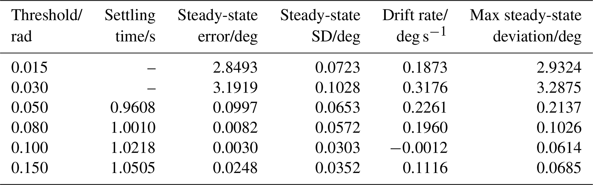
The min–max normalization method is employed to remove the influence of different physical dimensions and numerical ranges among the evaluation indices:
where ηi denotes the original value of a performance index and denotes its normalized value.
A five-index composite cost function is then established to comprehensively evaluate the threshold-dependent performance:
where , , , , and denote the normalized settling time, steady-state error, steady-state standard deviation, drift rate, and maximum steady-state deviation, respectively. The weights are selected as
A larger weight is assigned to the steady-state error because accurate balance near the equilibrium is a primary requirement for wheelchair stabilization. A lower value of J5 indicates better overall control performance.
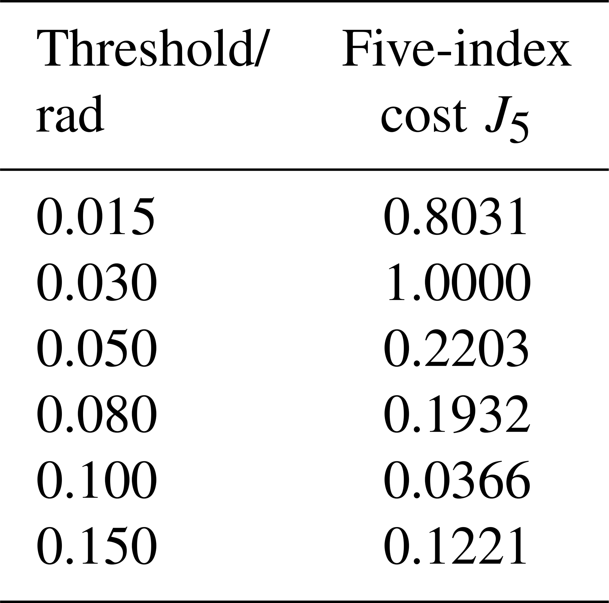
The calculated five-index costs are summarized in Table 3. The results show that smaller thresholds lead to shorter settling time in some cases, but they may also produce larger steady-state error and fluctuation. As the threshold increases, the steady-state behavior improves within a certain range, while the settling time gradually increases. Among the tested candidates, θsw=0.100 rad yields the minimum five-index cost, indicating the best overall trade-off between transient recovery and steady-state regulation under the nominal model parameters.
Table 3Five-index costs under different switching thresholds under nominal model parameters.
3.4.3 Parameter sensitivity of the selected threshold
To examine whether the selected switching threshold strongly depends on nominal model parameters, a one-factor-at-a-time sensitivity analysis was further conducted. The equivalent upper-body mass mp and the equivalent pendulum length L were varied independently. For each parameter factor, the threshold was scanned within the local range of 0.08–0.12 rad, and the optimal threshold was selected according to the minimum five-index cost.
For the equivalent mass variation, the mass factor is defined as
The optimal threshold decreases as the equivalent mass increases. A linear fitting gives
with R2=0.945. This negative correlation indicates that a larger equivalent upper-body mass tends to require a smaller switching threshold, allowing NMPC to remain active over a wider angular region before switching to LQR. It should also be noted that the optimal thresholds for the 0.8 and 0.9 mass factors are located at the upper boundary of the tested interval, suggesting that the optimal threshold may shift slightly upward when the equivalent mass decreases.
For the equivalent pendulum-length variation, the optimal threshold does not show a strictly monotonic trend. Under several length-variation cases, the minimum J5 occurs at the lower boundary of the tested interval, namely θsw=0.08 rad. This indicates that when the center-of-mass-related parameter deviates from the nominal value, a smaller switching threshold is generally beneficial because NMPC remains active over a wider angular region and provides stronger nonlinear recovery capability.
Table 4Optimal switching thresholds under representative parameter variations.
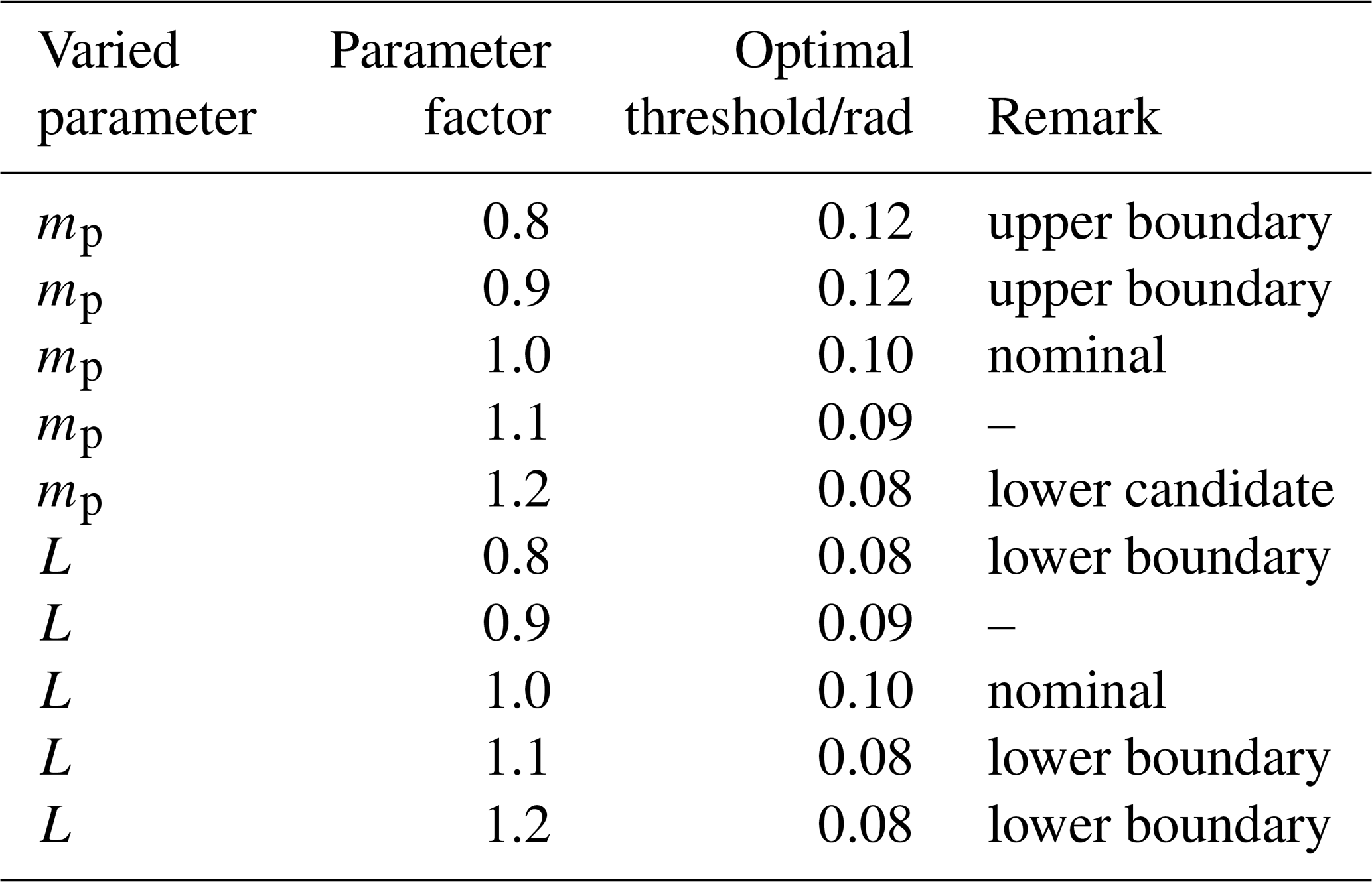
Overall, the nominal threshold evaluation identifies θsw=0.100 rad as the best fixed switching threshold under the nominal model parameters. The mass-sensitivity analysis further provides an empirical estimate of the optimal threshold within the tested mass range. For , the fitted relation indicates that a larger equivalent mass generally requires a smaller switching threshold. Therefore, θsw=0.100 rad is adopted as the nominal fixed threshold, while the fitted mass–threshold relation provides a reference for parameter-dependent threshold adjustment within the tested range.
3.5 Stability considerations
The stability consideration of the proposed controller is based on the functional division between NMPC and LQR. LQR is not used over the entire nonlinear operating range but is restricted to the near-equilibrium region verified by the linearization-error analysis in Sect. 3.4. In this region, the nonlinear model is linearized around the equilibrium point, and the LQR gain is designed so that the closed-loop matrix Al−BlK is Hurwitz. Thus, the LQR stage provides local asymptotic stability for the linearized system.
For states outside the local region, NMPC is activated to handle large-deviation nonlinear recovery under input constraints. The switching threshold therefore serves as a boundary between nonlinear recovery and local stabilization, preventing premature use of LQR in regions where the linear approximation is less reliable.
The above discussion provides a local stability guarantee for the LQR stage and a practical stability argument for the hybrid framework. Rigorous global Lyapunov proof for the completely switched nonlinear system is beyond the scope of this study. Therefore, the overall closed-loop behavior is validated through large-initial-angle simulations, disturbance tests, parameter-sensitivity tests, friction-coefficient tests, and prototype experiments.
4.1 Prototype
The desktop-scale two-wheeled self-balancing prototype used for experimental validation was developed based on the WHEELTEC B570 balancing vehicle architecture and employed an STM32F103C8T6 microcontroller together with an MPU6050 sensor for attitude measurement and closed-loop control implementation.
4.2 Simulation
Simulink in MATLAB is used to construct the simulation platform. The model includes the wheelchair body, driving wheels, center-of-mass and inertia parameters, external-disturbance input, and state-output modules. The body is modeled as a rigid body pitching about the wheel axis, and the driving torque is applied through the wheel-actuator module. The outputs include the pitch angle, pitch angular velocity, wheel displacement, and wheel velocity, which are used by the LQR, NMPC, and hybrid controllers. Disturbance input ports are reserved for robustness tests. The corresponding signal–flow relationship is shown in Fig. 4.
4.2.1 Numerical discretization of the NMPC model
The continuous-time nonlinear dynamic model is numerically discretized before being incorporated into the finite-horizon optimization problem. The state evolution is approximated with high accuracy by jointly utilizing the state values and dynamic information at both ends of the interval as well as the midpoint state in each sampling interval:
where Δt is the sampling interval; xm,k is the midpoint state; and um,k is the midpoint control input, which can be approximated as . The resulting discrete state–transition relationship enables the construction of the discrete prediction model required by NMPC. Based on the above discrete state–transition relationship, the NMPC problem is formulated as a nonlinear programming problem over a finite prediction horizon. The optimization variables include the state sequence and control input sequence over the prediction horizon, while the constraints include consistency between the current state and the measured state, discrete state–transition constraints, and upper and lower bounds on the control input. To guarantee real-time performance and closed-loop robustness, a receding-horizon optimization mechanism is adopted. At each sampling instant, the optimization problem is reformulated using the current measured state as the initial condition. The optimal future control sequence is computed, and only the first control input is implemented.
4.3 Balance verification
4.3.1 Comparative simulation under large initial tilt angles
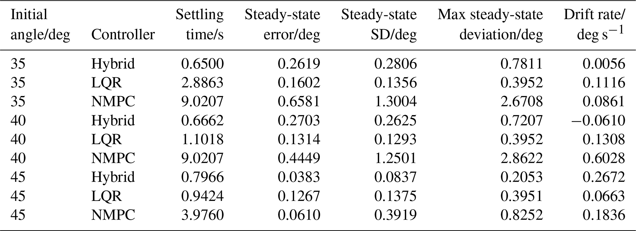
The recovery motion of the self-balancing wheelchair is simulated under initial tilt angles of 35, 40, and 45°. The standalone LQR controller, the standalone NMPC controller, and the proposed hybrid NMPC–LQR controller are compared under the same system parameters, input constraints, and simulation settings. The representative response curves are shown in Fig. 5, and the quantitative performance indices are summarized in Table 5.
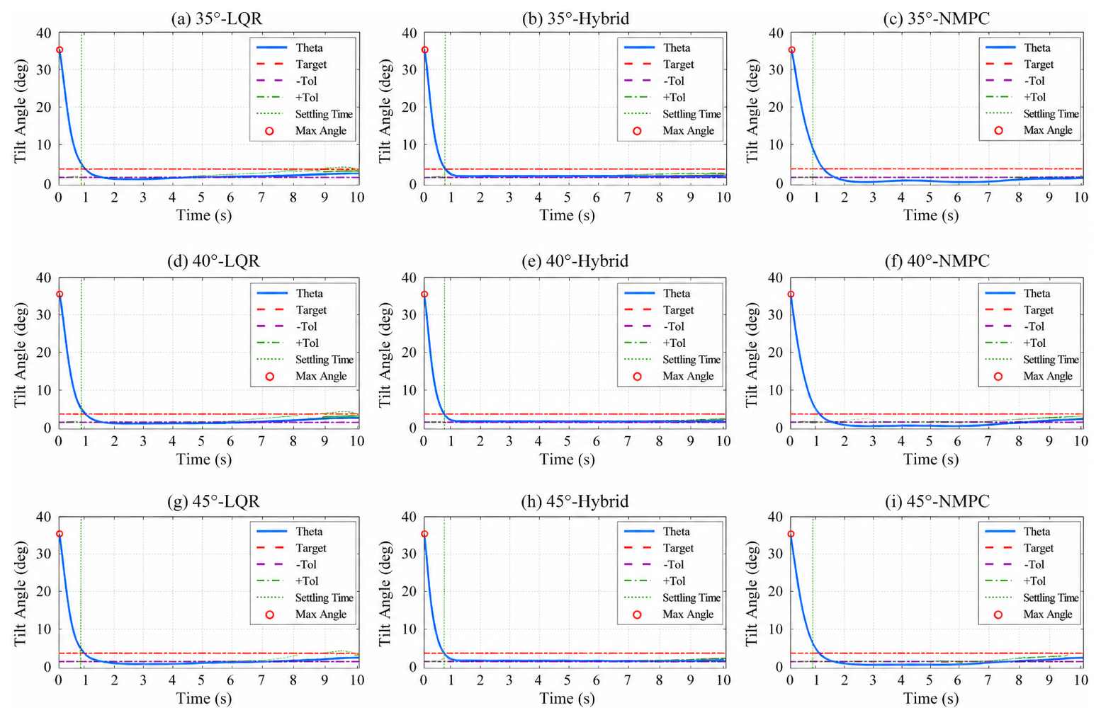
Figure 5Comparative simulation responses of the LQR, NMPC, and hybrid controllers under initial tilt angles of 35, 40, and 45°.
Table 5Performance comparison of LQR, NMPC, and hybrid controllers under large initial tilt angles.
4.3.2 Benchmark comparison with sliding-mode control
The SMC controller was tested using the same simulation model and input constraint as the proposed controller. Since sliding-mode control is widely applied to nonlinear systems, it provides a meaningful benchmark for evaluating the proposed hybrid strategy. Recent studies have also used SMC as a robust benchmark to evaluate intelligent LQR-based controllers for inverted-pendulum-type systems (Saleem et al., 2025).
Table 6Performance of the SMC benchmark under different recoverable initial tilt angles.
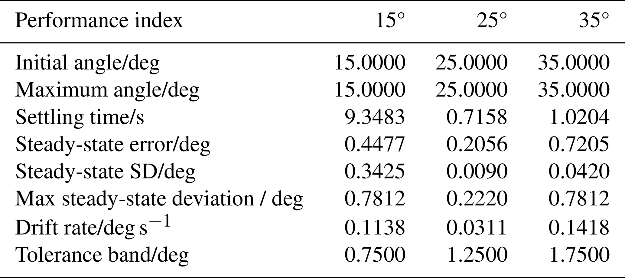
Table 7Recoverability comparison between the proposed hybrid NMPC–LQR controller and the SMC benchmark under different initial tilt angles.

4.3.3 Comparative analysis of control performance
Table 5 shows that the proposed hybrid controller achieves the shortest settling time under all three large-initial-angle conditions. At 35 and 40°, LQR gives slightly smaller steady-state error and fluctuation, reflecting its local regulation advantage. However, the standalone LQR controller has weaker large-deviation recovery capability, whereas the standalone NMPC controller shows longer settling time and larger residual oscillation.
At 45°, the hybrid controller achieves the fastest recovery and the smallest steady-state error, standard deviation, and maximum steady-state deviation. This indicates that NMPC improves large-angle nonlinear recovery, while LQR enhances local stabilization after the state enters the near-equilibrium region.
The SMC benchmark results in Tables 6 and 7 show that SMC fails under 40 and 45°, whereas the proposed hybrid controller remains stable under all tested initial angles. Therefore, the hybrid NMPC–LQR controller provides a better balance between recoverability, local stabilization, and robustness under the same input constraint.
4.3.4 Computational efficiency test
A computational time test was conducted under the same simulation conditions to evaluate the computational efficiency of the proposed hybrid controller. Five repeated runs were performed under the same simulation settings. The average computation time decreases from 48.04 min for standalone NMPC to 35.00 min for the hybrid controller, indicating that the proposed switching strategy reduces the online computational burden. The detailed results are provided in Appendix B.
4.3.5 External disturbance test
The disturbance-rejection capability of the hybrid controller is evaluated using both pulse and step disturbances. The disturbance magnitudes are 50, 65, 70, and 80 N, and the response curves are provided in Appendix A.
The system exhibits a secondary pitch deflection after the pulse is applied, but no sustained divergence is observed. Under 50 and 65 N disturbances, the wheelchair quickly returns to the stable region. Under 70 and 80 N disturbances, the recovery process becomes longer and the residual oscillation increases, but the response remains bounded. These results indicate that the proposed controller retains disturbance-rejection capability under representative pulse impacts.
In addition to the pulse-disturbance test, a step-disturbance test was conducted to evaluate the response of the proposed controller under persistent external force. The step disturbance was applied at t=2 s after the initial recovery process, and the tested disturbance magnitudes were 10, 20, and 30 N. The detailed response curves are provided in Appendix D. The results show that the post-step peak deviation increases with the disturbance magnitude. Specifically, the maximum post-step pitch deviations are 3.62, 5.89, and 8.11° under 10, 20, and 30 N step disturbances, respectively. Nevertheless, the responses remain bounded and gradually return to the near-equilibrium region. This indicates that the proposed hybrid controller can maintain recovery capability under persistent external disturbances.
4.3.6 Flat-ground friction-coefficient robustness test
Flat-ground simulations were further conducted to examine the influence of wheel–ground friction uncertainty. The slope angle was set to zero, and all controller parameters were kept unchanged. Only the static friction coefficient in the spatial contact model was varied. The tested coefficients were 0.03, 0.10, and 0.30, corresponding to low-, medium-, and high-friction contact conditions, respectively.
Table 8Flat-ground robustness test under different static friction coefficients.
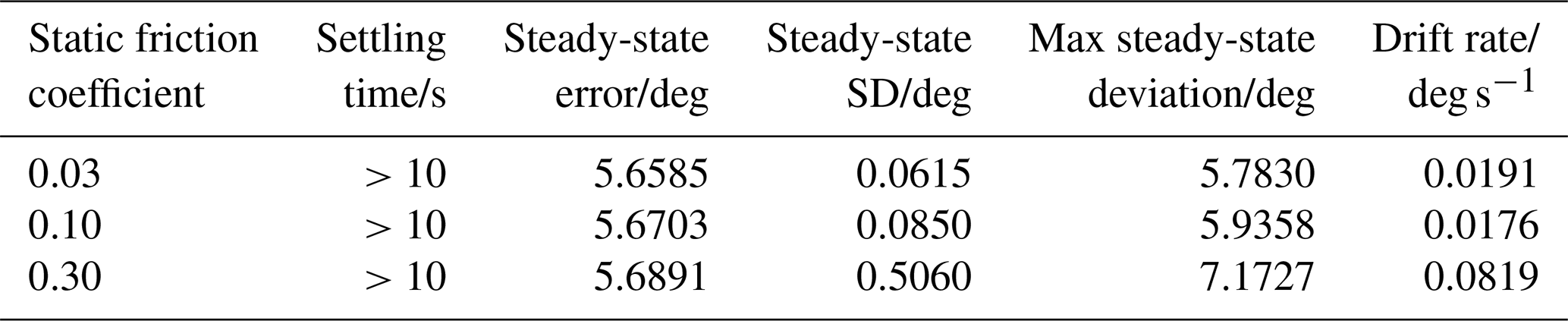
The results in Table 8 show that the wheelchair does not overturn under the tested friction coefficients, indicating bounded recovery under friction-parameter variations. The steady-state error changes slightly from 0.03 to 0.10, while the high-friction case of 0.30 produces larger steady-state fluctuation. This suggests that stronger wheel–ground contact interaction may amplify residual pitch oscillations.
Since the responses do not enter and remain within the prescribed error band during the 10 s simulation, these results are interpreted as bounded recovery rather than exact convergence to the upright target. The detailed response curves are provided in Appendix C, where the final steady-state mean angle is also marked for each friction condition.
4.3.7 Prototype balance-recovery experiments
Prototype balance-recovery experiments were conducted under initial tilt angles of 25, 30, and 35°. The measured responses are shown in Fig. 6. In all cases, the prototype recovers to a small neighborhood around the upright equilibrium, indicating the physical realizability of the proposed controller.
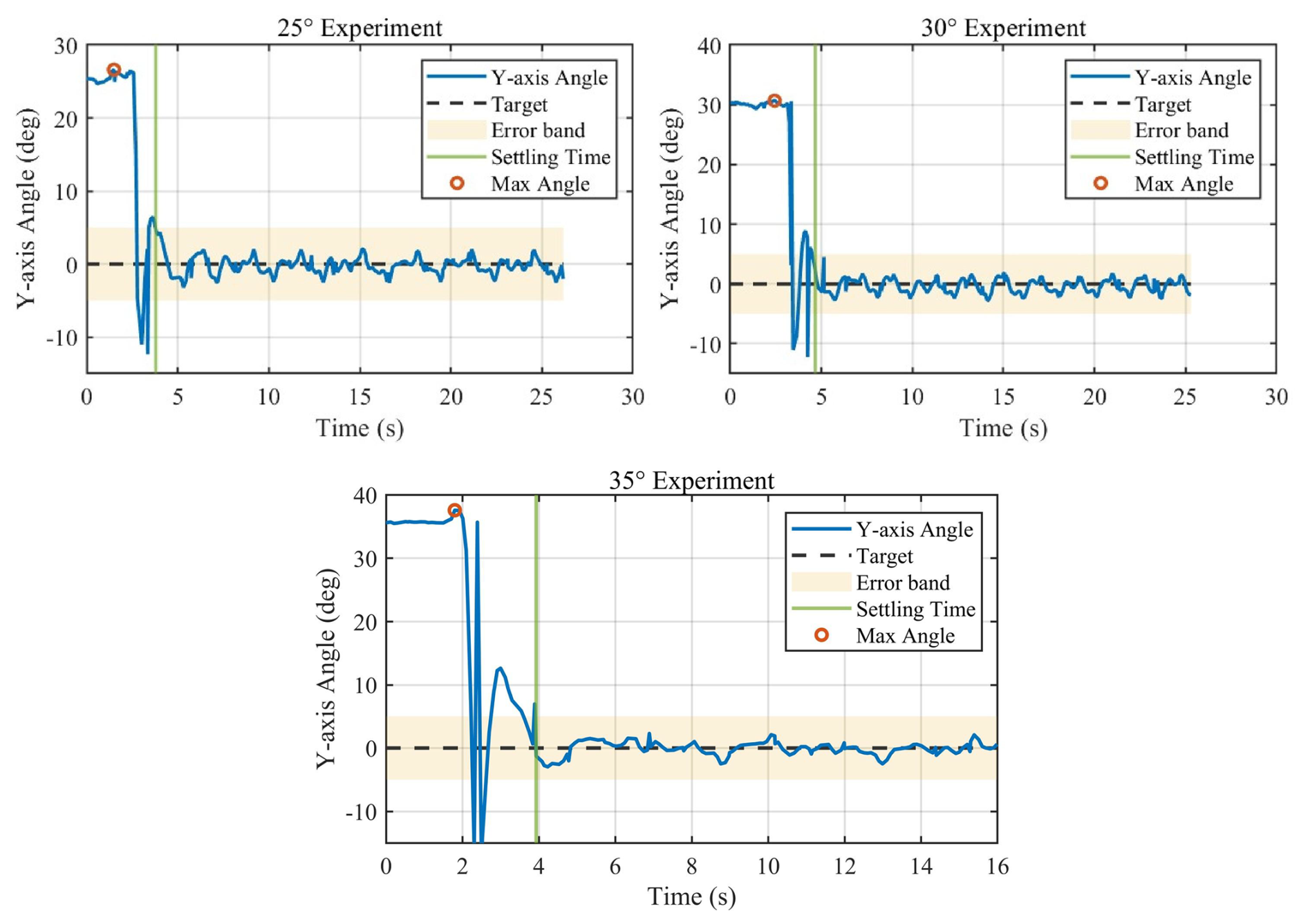
Figure 6Prototype balance-recovery experiment results under initial tilt angles of 25, 30, and 35°.
When the initial angle increases, the transient rebound and oscillation become more evident. Nevertheless, the response remains bounded and eventually approaches the upright region. These experimental results are consistent with the simulation trends and further support the engineering applicability of the proposed hybrid control strategy.
This paper develops a hybrid NMPC–LQR balance control strategy for two-wheeled self-balancing wheelchairs. NMPC is used for large-deviation nonlinear recovery, while LQR is restricted to the local stabilization region verified by linearization-error analysis. Comparative simulations, SMC benchmark tests, disturbance tests, friction-coefficient tests, and prototype experiments show that the proposed controller improves large-angle recovery capability while reducing the computational burden compared with the standalone NMPC.
For switching-threshold selection, the linearization-error analysis is first used to determine the threshold search range. A normalized five-index evaluation criterion is then adopted to compare different threshold candidates. Under the nominal model parameters, θsw=0.100 rad gives the lowest comprehensive cost and is selected as the nominal fixed threshold. The mass-sensitivity analysis further provides an empirical estimate of the optimal threshold within the tested mass range. For , the fitted relation indicates that a larger equivalent upper-body mass generally requires a smaller switching threshold.
Several limitations remain. The model is a planar reduced-order model and does not include yaw, roll, tire deformation, lateral instability, or active human-body motion. The stability discussion is based on local LQR analysis and closed-loop simulations rather than rigorous global Lyapunov proof for the switched nonlinear system. In addition, the prototype experiments are conducted on a desktop-scale platform. Future work will focus on human–wheelchair coupled modeling, multi-parameter threshold fitting, adaptive switching-threshold calculation, explicit friction compensation, robust NMPC with terminal constraints, and full-scale experiments on slopes and uneven terrains.
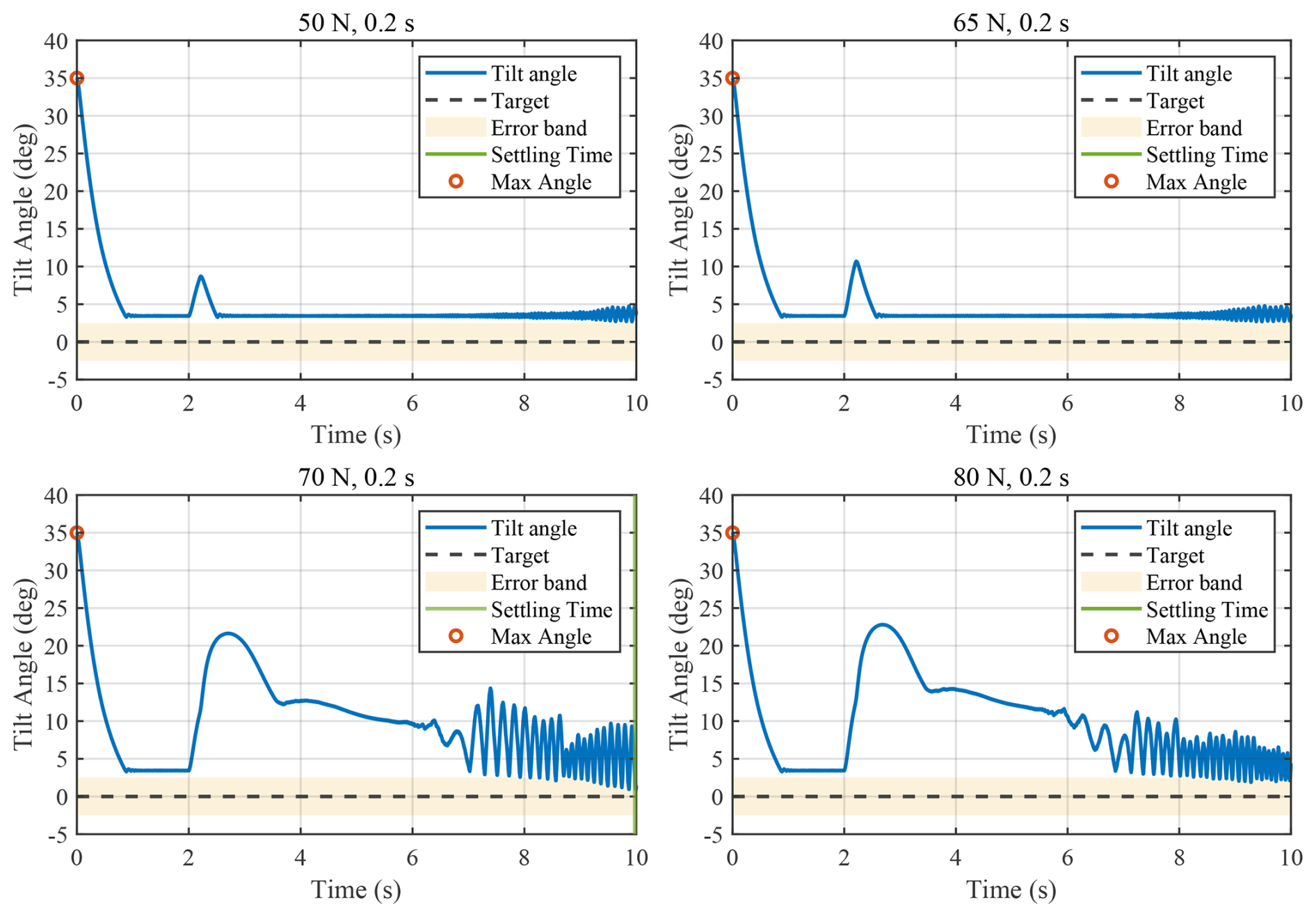
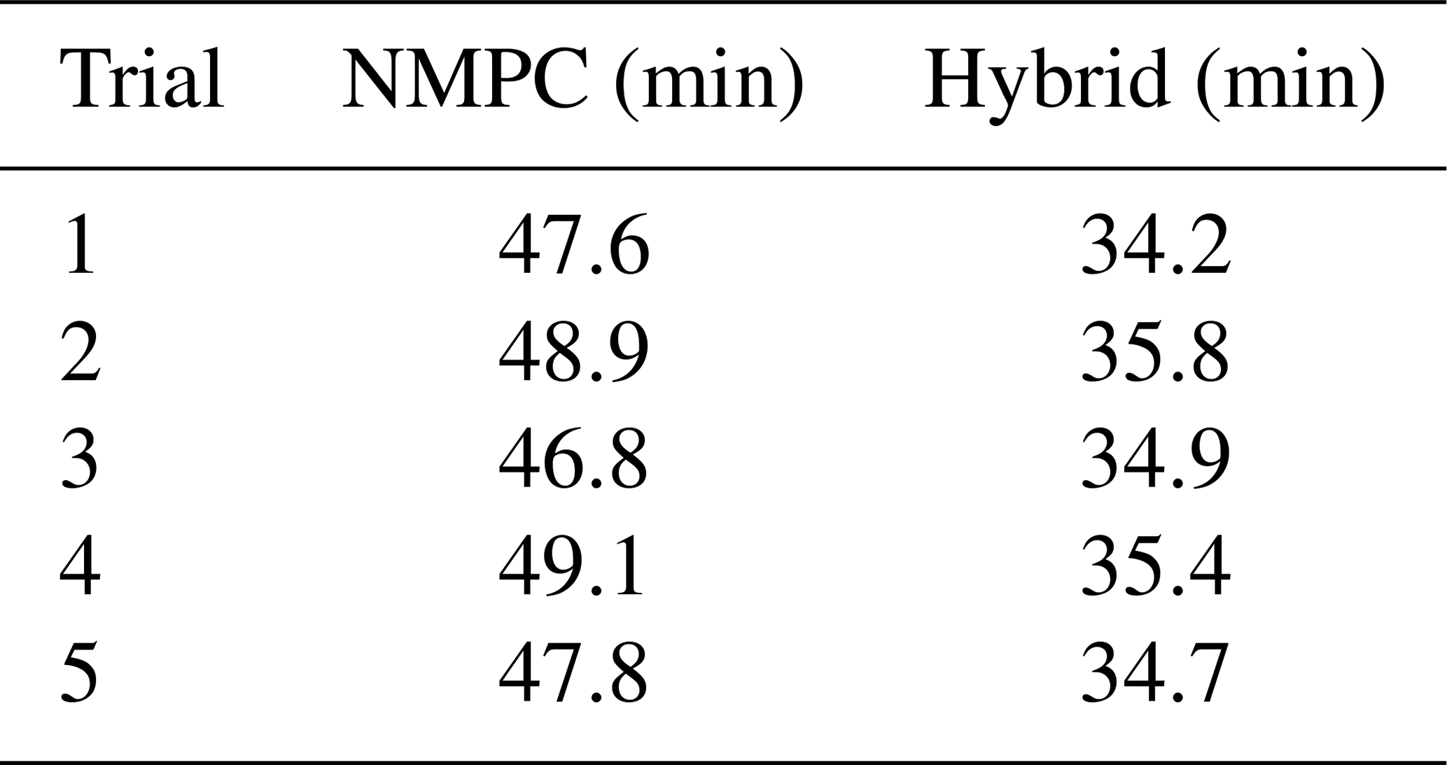
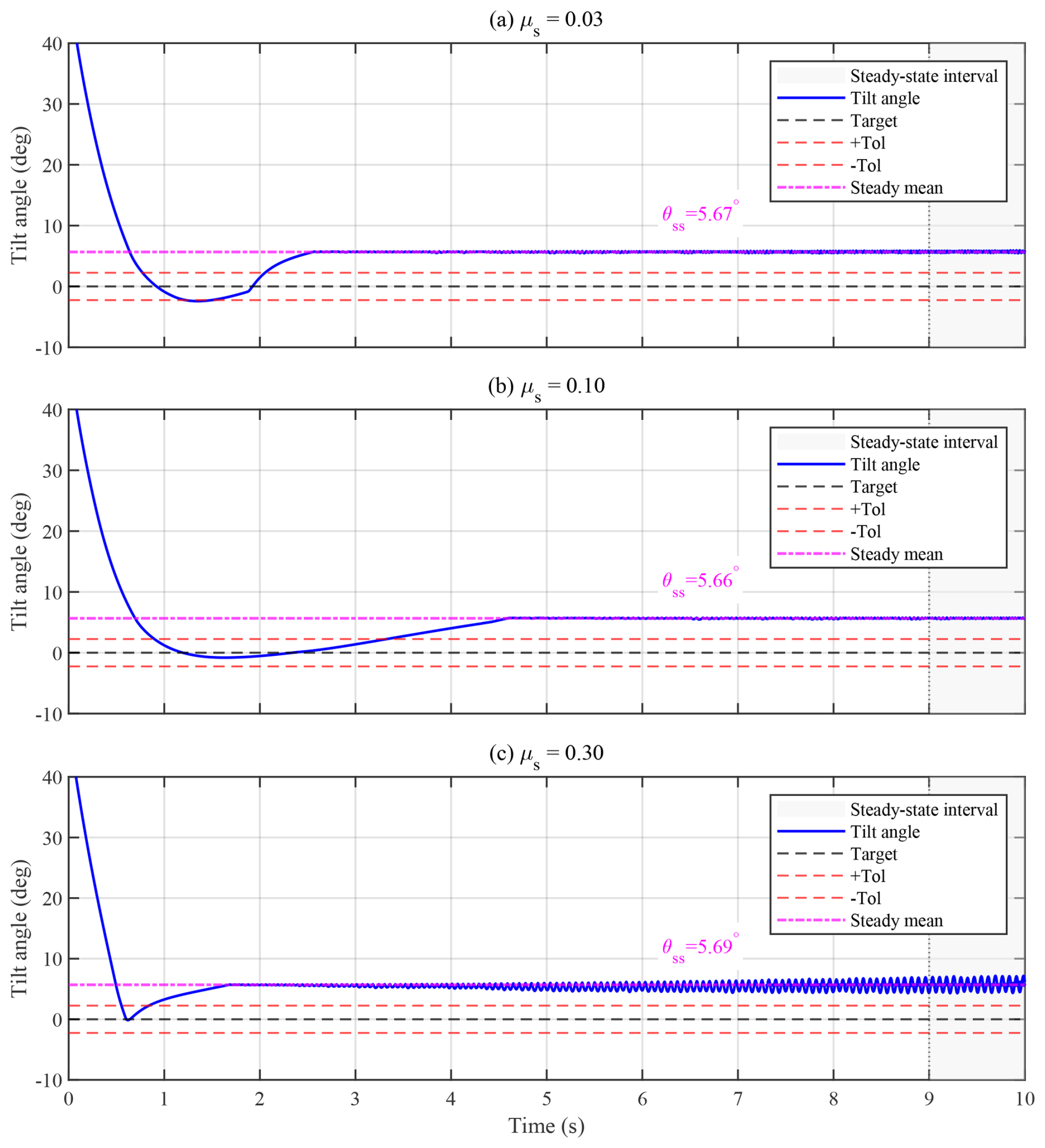
Figure C1Pitch-angle responses under different flat-ground static friction coefficients. The horizontal dash-dotted line denotes the final steady-state mean angle θss, calculated from the last 10 % of the simulation time.
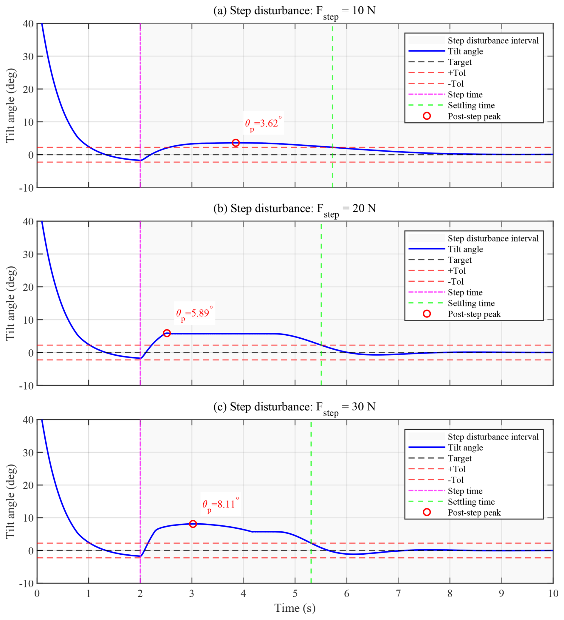
Figure D1Pitch-angle responses under different step disturbances. The shaded region denotes the period after the step disturbance is applied, and the red marker indicates the maximum post-step pitch deviation.
The code and data used in this study are not publicly available due to laboratory confidentiality requirements. Relevant information may be made available by the corresponding author upon reasonable request and with permission from the laboratory.
Haomin Sun contributed to algorithm design, dynamic modeling, and hardware implementation. Xinying Zhang contributed to simulation system development and simulation experiment design. Yaozhi Gu performed data processing. Weiyue Chen and Shuyue Zhang contributed to manuscript preparation.
The contact author has declared that none of the authors has any competing interests.
Publisher's note: Copernicus Publications remains neutral with regard to jurisdictional claims made in the text, published maps, institutional affiliations, or any other geographical representation in this paper. The authors bear the ultimate responsibility for providing appropriate place names. Views expressed in the text are those of the authors and do not necessarily reflect the views of the publisher.
The authors thank Chongyu Wang, Lin Gui, Dongyang Shao, and Wenhao Yan for their participation. The authors used ChatGPT for language polishing and LaTeX-formatting assistance. All scientific content, data interpretation, and conclusions were checked and approved by the authors.
This research has been supported by the Shanghai High-Quality Development Program for Science and Technology Industry–Elderly Care Technology Support Project (grant no. 25YL1900900).
This paper was edited by Liangliang Cheng and reviewed by four anonymous referees.
Chacko, S. J. and Abraham, R. J.: On LQR controller design for an inverted pendulum stabilization, Int. J. Dynam. Control, 11, 1584–1592, https://doi.org/10.1007/s40435-022-01079-0, 2023.
Chénier, F., Marquis, E., and Fleury-Rousseau, M.: Tracking the whole-body centre of mass of humans seated in a wheelchair using motion capture, J. Biomech., 156, 111675, https://doi.org/10.1016/j.jbiomech.2023.111675, 2023.
Cui, R., Guo, J., and Mao, Z.: Adaptive backstepping control of wheeled inverted pendulums models, Nonlinear Dynam., 79, 501–511, https://doi.org/10.1007/s11071-014-1682-9, 2015.
Dai, F., Gao, X., Jiang, S., Guo, W., and Liu, Y.: A two-wheeled inverted pendulum robot with friction compensation, Mechatronics, 30, 116–125, https://doi.org/10.1016/j.mechatronics.2015.06.011, 2015.
Feng, X., Liu, S., Yuan, Q., Xiao, J., and Zhao, D.: Research on wheel-legged robot based on LQR and ADRC, Sci. Rep., 13, 15122, https://doi.org/10.1038/s41598-023-41462-1, 2023.
Huynh, H. N., Verlinden, O., and Vande Wouwer, A.: Comparative application of model predictive control strategies to a wheeled mobile robot, J. Intell. Robot. Syst., 87, 81–95, https://doi.org/10.1007/s10846-017-0500-2, 2017.
Kim, S. and Kwon, S.: Dynamic modeling of a two-wheeled inverted pendulum balancing mobile robot, Int. J. Control Autom. Syst., 13, 926–933, https://doi.org/10.1007/s12555-014-0564-8, 2015.
Kim, Y., Kim, S. H., and Kwak, Y. K.: Dynamic analysis of a nonholonomic two-wheeled inverted pendulum robot, J. Intell. Robot. Syst., 44, 25–46, https://doi.org/10.1007/s10846-005-9022-4, 2005.
Li, J., Wang, J., Wang, S., Qi, W., Zhang, L., Hu, Y., and Su, H.: Neural approximation-based model predictive tracking control of non-holonomic wheel-legged robots, Int. J. Control Autom. Syst., 19, 372–381, https://doi.org/10.1007/s12555-019-0927-2, 2021.
Li, Z. and Zhang, Y.: Robust adaptive motion/force control for wheeled inverted pendulums, Automatica, 46, 1346–1353, https://doi.org/10.1016/j.automatica.2010.05.015, 2010.
Liang, S., Wang, Z., and Stepan, G.: Motion control of a two-wheeled inverted pendulum with uncertain rolling resistance and angle constraint based on slow-fast dynamics, Nonlinear Dynam., 104, 2185–2199, https://doi.org/10.1007/s11071-021-06439-7, 2021.
Liu, C., Qin, K., Xin, G., Li, C., and Wang, S.: Nonlinear model predictive control for a self-balancing wheelchair, IEEE Access, 12, 28938–28949, https://doi.org/10.1109/ACCESS.2024.3368853, 2024.
Ma, Y., Meng, F., and Xiong, S.: Design and implementation of a two-wheeled self-balancing car using a fuzzy Kalman filter, Appl. Sci., 14, 5296, https://doi.org/10.3390/app14125296, 2024.
Onozuka, Y., Tomokuni, N., Murata, G., and Shino, M.: Attitude control of an inverted-pendulum-type robotic wheelchair to climb stairs considering dynamic equilibrium, Robomech J., 7, 23, https://doi.org/10.1186/s40648-020-00171-4, 2020.
Saleem, O., Mahmood-ul-Hasan, K., and Rizwan, M.: An experimental comparison of different hierarchical self-tuning regulatory control procedures for under-actuated mechatronic systems, PLOS ONE, 16, e0256750, https://doi.org/10.1371/journal.pone.0256750, 2021.
Saleem, O., Iqbal, J., and Alharbi, S.: Self-regulating fuzzy-LQR control of an inverted pendulum system via adaptive hyperbolic error modulation, Machines, 13, 939, https://doi.org/10.3390/machines13100939, 2025. a
Shen, J. and Hong, D.: Model predictive control using dynamic model decomposition applied to two-wheeled inverted pendulum mobile robot, in: 2022 19th International Conference on Ubiquitous Robots (UR), Jeju, Republic of Korea, 332–337, https://doi.org/10.1109/UR55393.2022.9826244, 2022.
Xin, G., Jin, B., Liu, C., and Jiang, M.: A unified control framework for self-balancing robots: addressing model variations in wheel-legged platforms and human-carrying wheelchairs, Sensors, 25, 7144, https://doi.org/10.3390/s25237144, 2025.
Yan, C. and Li, X.: Research on stability control system of two-wheel heavy-load self-balancing vehicles in complex terrain, Appl. Sci., 14, 7682, https://doi.org/10.3390/app14177682, 2024.
Zhang, A., Zhou, R., Zhang, T., Zheng, J., and Chen, S.: Balance control method for bipedal wheel-legged robots based on friction feedforward linear quadratic regulator, Sensors, 25, 1056, https://doi.org/10.3390/s25041056, 2025.
Zhang, B. and Wu, G.: Design of two-wheel self-balancing vehicle based on visual identification, EURASIP J. Image Video Process., 2019, 34, https://doi.org/10.1186/s13640-019-0434-7, 2019.
Zhang, H. and Mohamad Nor, N.: Control strategies for two-wheeled self-balancing robotic systems: a comprehensive review, Robotics, 14, 101, https://doi.org/10.3390/robotics14080101, 2025.
Zhang, Z., Xu, P., Wu, C., and Yu, H.: Smart nursing wheelchairs: a new trend in assisted care and the future of multifunctional integration, Biomimetics, 9, 492, https://doi.org/10.3390/biomimetics9080492, 2024.
- Abstract
- Introduction
- Modeling
- Hybrid NMPC–LQR control method
- Experiments
- Conclusions
- Appendix A: Pitch-angle responses under external pulse disturbances
- Appendix B: Detailed results of the computational time tests
- Appendix C: Pitch-angle responses under different flat-ground friction coefficients
- Appendix D: Pitch-angle responses under step disturbances
- Code and data availability
- Author contributions
- Competing interests
- Disclaimer
- Acknowledgements
- Financial support
- Review statement
- References
- Abstract
- Introduction
- Modeling
- Hybrid NMPC–LQR control method
- Experiments
- Conclusions
- Appendix A: Pitch-angle responses under external pulse disturbances
- Appendix B: Detailed results of the computational time tests
- Appendix C: Pitch-angle responses under different flat-ground friction coefficients
- Appendix D: Pitch-angle responses under step disturbances
- Code and data availability
- Author contributions
- Competing interests
- Disclaimer
- Acknowledgements
- Financial support
- Review statement
- References