the Creative Commons Attribution 4.0 License.
the Creative Commons Attribution 4.0 License.
 | 05 Mar 2024
Design and obstacle-crossing analysis of a four-link rocker-suspension planetary exploration robot
Zhen Song
Zirong Luo
Huixiang Xie
At present, there are still many meteorite craters and boulders on the surface of Mars and the Moon that cannot be accessed by existing planetary exploration robots. To provide a solution to this issue, this paper proposes a four-link rocker-suspension planetary exploration robot that combines both the reliability and low complexity of wheeled rovers with competent terrain adaptability and obstacle-crossing performance. Relying on its special differential pitch device, the robot can adapt to fluctuations in terrain by using both active and passive modes. Moreover, the four-link rocker suspensions on both sides of the robot can increase the instantaneous rotation radius of the rockers when the robot climbs over obstacles. In this paper, using modelling and simulations, we demonstrate that the four-link rocker suspension can improve the robot's obstacle-crossing capability. The geometric and static conditions required for the robot to cross obstacles are derived and discussed, and numerical simulations are conducted to identify the maximum obstacle-crossing heights that satisfy different conditions. Finally, a physical prototype of the robot is developed.
- Article
(9981 KB) - Full-text XML
- BibTeX
- EndNote


Due to the increasing interest in space exploration, a variety of mobile robots have been sent to the surface of the Moon and Mars for exploration missions (Zhang et al., 2021). However, there are still many meteorite craters and boulders on the surface of these planetary bodies that existing robots cannot easily explore. This has resulted in higher requirements with respect to the terrain adaptability and obstacle-crossing capability of planetary rovers (Zakrajsek et al., 2005). In addition, these exploration robots have to overcome the outer-space environment, which is characterized by low gravity, high vacuum, heavy radiation, extreme hot or cold, and weak magnetic fields. Therefore, it is of great practical significance to develop a planetary exploration robot with strong obstacle-crossing capability and terrain adaptability while maintaining the other advantages of existing planetary rovers.
Currently, six-wheeled rocker–bogie rovers represent the most mature technology in this field and are the most widely applied robot type. From the Sojourner in 1997 (Lindemann and Voorhees, 2005; Bogue, 2012) and the Spirit and Opportunity in 2003 (Squyres and Crater, 2004) to Perseverance (Sharafa et al., 2020), the lunar exploration robot (Zhai et al., 2018) and Jade Rabbit 2 (Zhang et al., 2014) today, six-wheeled rocker–bogie rovers show excellent terrain adaptability and manoeuvrability on uneven planetary surfaces. The rocker–bogie suspension can maintain all of the rover wheels in contact with the ground (Bruzzone and Quaglia, 2012). Furthermore, the pure mechanical structure makes additional control and actuate modules to adjust the rover's configuration unnecessary. Nevertheless, rocker–bogie suspensions not only increase the mass of the robot but also limit the robot's obstacle-crossing ability. When rocker–bogie robots climb steps and stairs, they often experience the undesired phenomenon that some wheels float from the ground, which may lead to mobile robot instability (Kim et al., 2012).
Some planetary exploration robots adopt an active and controllable chassis structure, such as the Sample Return Rover (SRR; Kozma et al., 2007, 2008), Tri-star (Aoki et al., 2013), Nomad (Cabrol et al., 2001a, b), Sherpa (Cordes et al., 2011; Roehr et al., 2014) and Scarab (Wettergreen et al., 2010). These robots can actively adjust their posture during movement and, thus, maintain the stability of their main bodies. The more flexible chassis structure and joints enhance their obstacle-crossing ability, but they also require the robots to adopt additional actuators or special control strategies, making their control system more complex (Siegwart et al., 2002). Nevertheless, the mechanical structure of this kind of robot is simpler.
However, the applicability of wheeled rovers in unstructured and steep terrain is limited. To overcome these limitations, legged robots provide a very promising alternative for space exploration, for instance, SpaceBok (Arm et al., 2019), SpaceClimber (Bartsch et al., 2010; Bartsch, 2014), Scorpion (Dirk and Frank, 2014), the bio-inspired Lunar Locust (Herkenhoff et al., 2021), WORMS (Lordos et al., 2023) and Spacebit (Excell, 2021). With respect to climbing rocks, crossing trenches, jumping over steep bunkers and other complex movements, legged robots have greater advantages, making them more suitable for exploring unknown areas with complex terrain and high scientific research value.
Hybrid wheeled-legged robots are another feasible scheme that combine the high-speed and efficient performance of wheeled robots with the adaptability of legged robots. Typical examples are ATHLETE (Wilcox, 2011; Sunspiral et al., 2012) and Chariot (Harrison et al., 2008), proposed by NASA, which are used to carry out transportation missions on the Moon. However, on the other hand, legged systems are mechanically complex because additional actuators and sensors are required to steadily maintain their balance, inevitably leading to slow movement (Kim et al., 2012). Furthermore, planning the walking motion online can be computationally expensive (Kolvenbach et al., 2017). The low-gravity environment on a planet's surface can also add more uncertainty to the robot's gait control, especially for robots with a dynamic gait. These reasons all lead to the limited application of legged robots in planetary exploration tasks that require high system stability and reliability. In fact, not all planetary surfaces are suitable for legged systems. For example, the surface of the Moon is covered with a 1–18 m thick layer of rock debris, making it easy for the joints of the leg structure to get stuck (Zakrajsek et al., 2005; Shkuratov and Bondarenko, 2001). Moreover, the rock debris may stick to the hinges on the leg.
Consequently, in this paper, we propose a four-link rocker-suspension planetary exploration robot that has both the reliability and low complexity of wheeled rovers and better terrain adaptability and obstacle-crossing performance. Hitherto, four-link mechanisms have been applied to many wheeled robots, such as Shrimp (Siegwart et al., 2002), CEDRA (Meghdari et al., 2005) and CRAB II (Thueer et al., 2006). Most of these robots adopt parallelogram four-link mechanisms. The four-link mechanisms on both sides of these robots not only improve the stability of their main bodies but also enhance their terrain adaptability. However, the four-link mechanisms on both sides do not significantly improve the robots' obstacle-crossing capability; therefore, Shrimp and CEDRA have a wheel mounted on a four-link mechanism located in front of the robot that will lift the front wheel if an obstacle is encountered.
Compared with the existing wheeled rovers, there are two superiorities of the proposed robot. Firstly, using a differential pitching device, it can passively or actively maintain the balance of its main body during motion. In the passive adaptation mode, the influence of terrain fluctuations on the pitch angle of the robot's main body will be reduced. In the active control mode, the robot can actively adjust the pitch angle of its main body to a specific angle according to task requirements. Secondly, it has a four-link mechanism to connect the primary and secondary rockers, which can increase the instantaneous turning radius of the rockers when the robot climbs over obstacles. This robot provides a feasible scheme to improve the climbing capability and terrain adaptability of wheeled planetary rovers without a complex control strategy or additional mechanical devices and sensors, which has a broad application prospect in future planetary exploration.
The rest of the paper is arranged as follows: Sect. 2 introduces the mechanical structure of the proposed robot; Sect. 3 illustrates a model of the geometric and static conditions required for the robot to cross obstacles; in Sect. 4, numerical simulation is conducted to analyse the obstacle-crossing capability of the robot; the development of the robot's physical prototype is presented in Sect. 5; and Sect. 6 provides a conclusion and an outlook with respect to future applications and improvement of the robot.
2.1 Mechanical structure
The physical prototype (Fig. 1a) and mechanical structure of the proposed robot are shown in Fig. 1. The robot consists of a main body and two four-link rocker suspensions on both sides (Fig. 1b). The rocker suspensions on both sides are connected by a differential pitching device (Fig. 1e), which is contained in the main body (Fig. 1c). By combining active and passive methods, this device enables the robot to adapt to the undulating changes in terrain during movement and also plays a role in adjusting the pitch angle of the main body. The four-link rocker suspension consists of a primary rocker, a secondary rocker, two connecting rods and three walking wheels (Fig. 1f). The primary and secondary rockers and the left and right connecting rods jointly form an isosceles trapezoidal four-link mechanism. In this four-link rocker suspension, the instantaneous rotation centre Ot of the primary and secondary rockers is positioned lower than the centre of the walking wheels when the robot is moving on flat ground (as shown in Fig. 1f), which is conducive to the robot crossing obstacles. As the overturning torque () caused by the pressure (N2) on the front walking wheel will drive the primary rocker to rotate relative to its instantaneous rotation centre Ot when the front walking wheel collides with an obstacle (as the instantaneous rotation centre of the primary and secondary rockers is lower than the centre of the wheel), it will be beneficial for the primary rocker to rotate clockwise, which will help the front walking wheels climb up along the obstacle. The further mathematical demonstration of this will be elaborated upon in Sect. 2.4. To enhance its manoeuvrability, the proposed robot adopts a six-wheel independent-drive system. There is a direct-current (DC) motor inside each wheel to independently drive its rotation (as shown in Fig. 1d and f). In addition, the four front and rear walking wheels can turn independently via a steering device, which is used to realize the robot's steering. The structure of the steering device is shown in Fig. 1d.
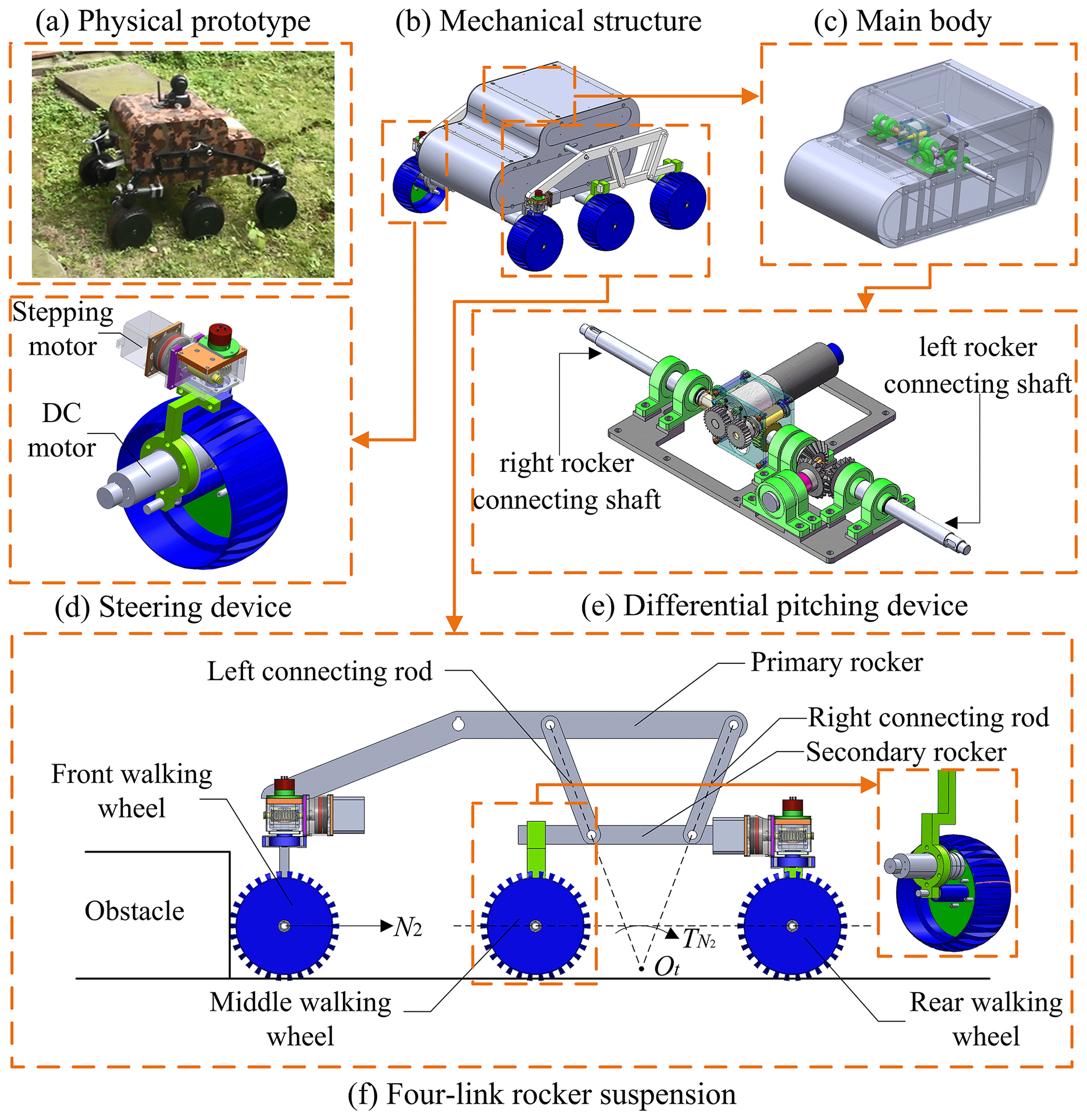
Figure 1Mechanical structure of the robot: (a) physical prototype; (b) mechanical structure; (c) main body; (d) steering device; (e) differential pitching device; (f) four-link rocker suspension.
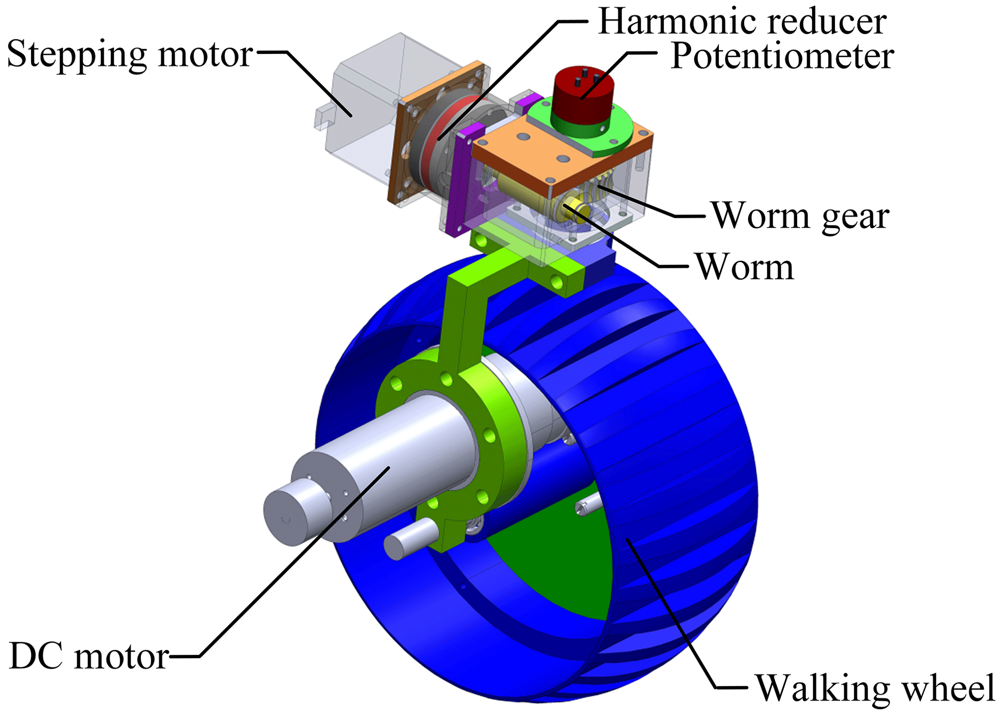
2.2 Steering device
In the four-link rocker suspension, the primary and secondary rockers can only rotate in relatively the same plane, but they cannot swing freely. Therefore, the robot's steering relies on the steering devices installed on the front and rear walking wheels. As shown in Fig. 2, the steering device constitutes a stepping motor, a harmonic reducer, a potentiometer, and a worm and worm gear mechanism. In the device, the stepping motor drives the worm and worm gear mechanism to realize the steering of the walking wheel, while the wheel is directly driven by a DC servo motor. The potentiometer on the top of the device measures the rotation angle of the walking wheel in real time, which constitutes a closed control loop and ensures that the wheel can rotate to a specific angle. The harmonic reducer is used to reduce the output speed of the stepping motor and increases the steering torque of the wheel.
2.3 Differential pitching device
Through the differential pitching device, the robot can reduce or control the pitch angle of the main body during movement. Figure 3 shows the composition (Fig. 3a, b) and a simplified mechanism diagram (Fig. 3c) of the device. The differential pitching device is composed of a differential bevel gear group and an active pitch control device. The differential bevel gear group has three bevel gears (1′, 2′ and 3′), which are assembled on the left rocker connecting shaft, the main body shaft and the worm gear shaft respectively. The worm gear shaft is coaxial with the right rocker connecting shaft, but they can rotate relative to each other and generate an angle difference through the active pitch control device. The bearing support of the main body shaft is directly installed on the device base, which is fixed on the main body, so the axis direction of the main body shaft is always the same as that of the main body.
The active pitch control device is formed by a group of fixed straight gears (Gear 1 and Gear 2), a worm (w) and worm gear (wg) mechanism, and a DC motor (m) fixed on the bracket. The right rocker connecting shaft is fixed on the motor bracket by a lantern ring, so the active pitch control device will always rotate synchronously with the right primary rocker. In the active pitch control device, the DC motor drives the worm and worm gear mechanism through a fixed gear group, which is used to increase the worm's speed. When the robot wants to actively adjust its main body's pitch angle, the DC motor will drive bevel gear 3′ to rotate relative to the right rocker connecting shaft through the worm and worm gear mechanism. (The absolute pitch angles of the left and right rocker connection shafts relative to the ground will not change due to the output torque of the DC motor.) Then, bevel gear 3′ will drive bevel gear 2′ to rotate relative to bevel gear 1′ through the differential bevel gear group. The main body shaft will also rotate around the left rocker connection shaft with bevel gear 2′. Because the main body shaft is fixed to the device base through the bearing support and the axis direction of the main body shaft is always the same as that of the main body, the robot's main body will also change its pitch angle accordingly. When the DC motor is turned off, bevel gear 3′ will rotate synchronously with the right primary rocker. Moreover, the pitch angle of the robot's main body relative to the ground mainly depends on the pitch angles of the left and right rocker connecting shafts relative to the ground. A detailed mathematical demonstration is given in the following.
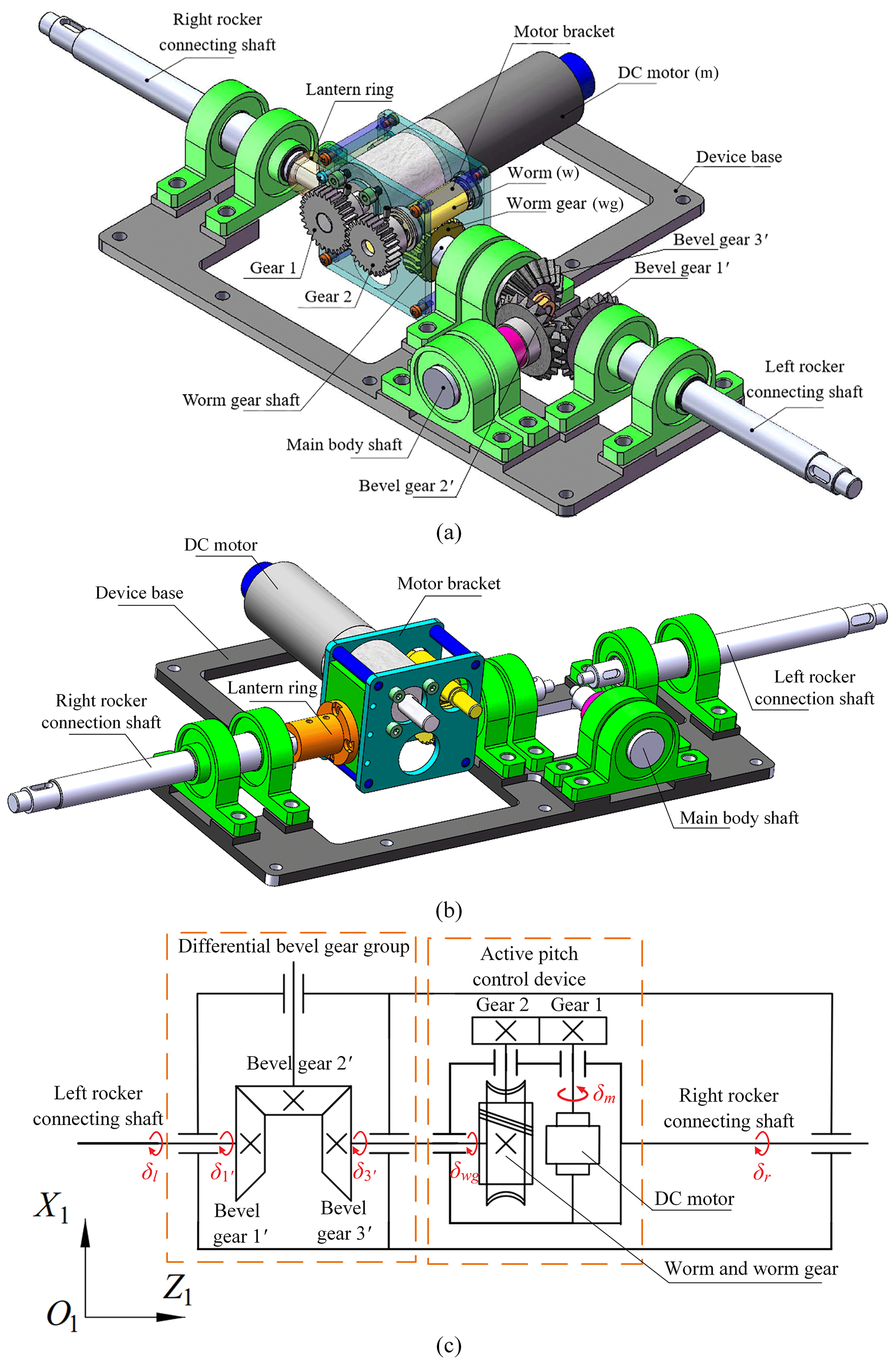
Figure 3Differential pitching device: (a) the composition of the differential pitching device; (b) the composition of the differential pitching device from another perspective; (c) a simplified mechanism diagram of the differential pitching device.
In Fig. 3c, the coordinate frame is that of the robot's main body, in which the X1 axis always points straight ahead of the main body and the X1–O1–Z1 plane always coincides with the device base.
From Fig. 3c, the mathematical relationship between the pitch angles of the left and right primary rockers relative to the device base (the coordinate frame ) can be calculated and derived. In the differential bevel gear group, the teeth numbers of the three bevel gears are the same, i.e. . Therefore, the relations between the bevel gears' rotation angles relative to the device base (the robot's main body coordinate frame ) can be obtained as follows:
In Eq. (1), δl, , and δwg represent the rotation angles of the left rocker connecting shaft, bevel gear 1′, bevel gear 3′ and the worm gear relative to the coordinate frame respectively. Their positive directions are marked using numerical values in Fig. 3c.
In the active pitch control device, the output speed of the DC motor is increased through the straight gears 1 and 2. Hence, the relation between the DC motor's output rotation angle and the worm's rotation angle relative to the device base can be derived as follows:
In Eq. (2), δm (the direction of δm is marked in Fig. 3c) and δw are the rotation angles of the DC motor and the worm relative to the device base (the coordinate frame ) respectively; z1 and z2 are the teeth numbers of the straight gears 1 and 2. In addition, because the right rocker connecting shaft is fixed on the motor bracket and rotates synchronously with the whole active pitch control device, the relation between the rotation angle of the right rocker connecting shaft (δr) relative to the device base and that of the worm gear can be derived as follows:
In Eq. (3), zw represent the number of worm's heads and zwg represent the number of worm's gear teeth. By combing Eqs. (1), (2) and (3), the relationship between the rotation angles of the left and right rocker connecting shafts relative to the device base can be obtained as follows:
It is assumed that α represents the pitch angle of the main body relative to the ground and that and represent those of the respective left and right primary rockers. Because the device base is fixed inside the main body, the pitch angle of it is equal to α and there are
By substituting Eq. (4) into Eq. (5), the pitch angle α of the main body relative to the ground can be expressed as follows:
From Eq. (6), it can be seen that the pitch angle of the left and right primary rockers and the output rotation angle of the DC motor jointly determine the pitch angle of the main body during robot motion. Moreover, through the differential pitching device, these respective influences have been halved. The pitch angle control of the robot's main body can be divided into two modes: the passive adaptation mode and the active control mode.
With respect to the passive adaptation mode, this mode can reduce the impact of terrain fluctuations on the pitch angle of the robot's main body. When the DC motor is turned off, the worm–worm gear mechanism is in a self-locking status, meaning that the right rocker connecting shaft and the worm gear shaft can rotate synchronously, i.e. δm=0. In this case, the robot can passively adapt to fluctuations in the terrain during motion. If the left primary rocker rotates a certain angle relative to the main body, through the differential bevel gear group, the right rocker will rotate the same angle relative to the main body in the opposite direction and vice versa. Thus, the pitch angle of the main body will always be half of the sum of the pitch angles of the primary rockers on both sides. The mathematical relationship between the pitch angles of the primary rockers and the main body can be expressed as follows:
With respect to the active control mode, this mode enables the robot to actively adjust the pitch angle of its main body to a specific angle according to task requirements. When the robot is moving on a slope but wants to keep its body horizontal or when the robot wants to keep its body at a specific angle for observation or operation, the active control mode will be activated by the operator via the remote control. The control commands sent by the remote control will be accepted by the internal control centre of the robot and converted into pulse-width modulation (PWM) signals to drive the DC motor to output the rotation angle. The output rotation angle of the DC motor is controlled via the proportional–integral–derivative (PID) closed-loop control. According to Eq. (6), the operator will control the DC motor to output a certain rotation angle, and the worm shaft will then be driven to rotate through the worm–worm gear mechanism. Next, in the differential bevel gear group, the main body shaft will rotate around the left rocker connecting shaft until the main body reaches the pitch angle expected by operators.
2.4 Four-link rocker suspension
Figure 4 shows the composition and structure of the robot's rocker suspension. d1–d9 (marked in Fig. 4b) represent the measurements of each respective part of the rocker suspension. As shown in Fig. 4a, the four-link rocker suspension is composed of a primary rocker, a secondary rocker, two connecting rods and three walking wheels. The primary and secondary rockers and the left and right connecting rods jointly form an isosceles trapezoidal four-link mechanism (A–B–C–D), in which the length of the left connecting rod A–C is equal to that of the right connecting rod B–D. To better characterize the geometric configuration of the four-link mechanism, the included angle between the upper connecting rod (A–B) and the left connecting rod (A–C) is defined as θ3, whereas the included angle between the upper connecting rod (A–B) and the lower connecting rod (C–D) is defined as θ2.
When the robot is climbing over an obstacle, the primary and secondary rocker will rotate accordingly. Different from the traditional rocker–bogie suspension, the proposed four-link rocker suspension can increase the instantaneous rotation radius of the primary and secondary rocker through the four-link mechanism, which makes the rotation torques applied from the obstacle's support forces to the rockers conducive to their rotation. This improves the obstacle-crossing capability of the robot.
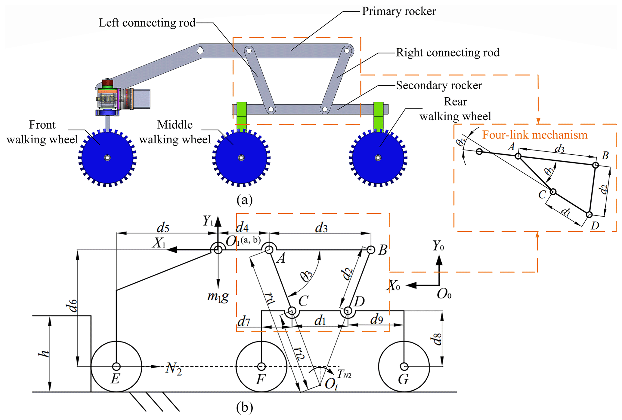
Figure 4Composition and structure of the rocker suspension: (a) the composition of the four-link rocker suspension; (b) the simplified structure of the rocker suspension.
As shown in Fig. 4b, the O0{X0,Y0} coordinate frame is a ground-fixed coordinate frame, whereas O1{X1,Y1} is the robot's main body coordinate frame located at the intersection of the centreline of the robot's main body and the rotation axes of the primary rockers on both sides. Let the coordinate of the origin O1 expressed in the ground-fixed coordinate frame O0{X0,Y0} be (a, b). The transformation matrix of the robot's body coordinate frame O1{X1,Y1} relative to the ground-fixed coordinate frame O0{X0,Y0} can be obtained in the homogeneous transformation matrix form as follows:
Draw the extension lines of the connecting rods A–C and B–D and make them intersect at point Ot. Point Ot is the instantaneous rotation centre of the primary and secondary rockers. In the coordinate frame O1{X1,Y1}, the coordinate vector of point Ot can be expressed as follows:
In Eq. (9) and Fig. 4b, represents the rotation radius of point A on the primary rocker about the instantaneous centre Ot, whereas represents that of point C on the secondary rocker. The respective values of and can be expressed as follows:
For example, when the front walking wheel makes contact with an obstacle, the coordinate vector of the centre of the front walking wheel (E) in O1{X1,Y1} can be expressed as follows:
We assume that the left and right rocker suspensions of the robot cross the obstacle simultaneously and that the robot does not actively adjust the pitch angle of the main body, i.e. the pitch angles of the left and right primary rockers are equal to that of the main body, . Because the direction of the support force (N2 in Fig. 4b) from the obstacle on the front walking wheel is perpendicular to the vertical surface of the obstacle, the rotation torque that N2 applies to the primary rocker can be expressed as follows:
In Eq. (13), N2 represents the vector of N2, 0T1 is the transformation matrix of the robot's body coordinate frame O1{X1,Y1} relative to the fixed coordinate frame O0{X0,Y0}, and and 1pE are the coordinate vectors of the point Ot and the centre of the front walking wheel (E) in O1{X1,Y1}. When the front walking wheel is climbing the obstacle, the primary rocker will rotate clockwise around the instantaneous centre Ot. Therefore, according to the right-hand principle, if is less than zero, it can be considered that the rotation torque applied by N2 is conducive to the rotation of the rocker. The same analysis method is also applicable to the robot's other wheels crossing obstacles.
From Eq. (13), it can be seen that the value of is related to the structural parameters of the robot. Therefore, we can optimize the structural parameters of the robot to make the torques that it receives more conducive to crossing obstacles. Hence, compared with traditional rocker–bogie suspensions, the four-link rocker suspension improves the obstacle-crossing capability of the proposed robot and make it climb over obstacles more easily. Further detailed analysis will be conducted in Sects. 3 and 4.
To analyse the optimal obstacle-crossing performance of the robot, it is assumed that the rocker suspensions of the robot cross a regular vertical obstacle simultaneously and that the robot does not actively adjust the pitch angle of the main body, meaning that the pitch angles of the left and right primary rockers are equal on both sides, i.e. . Furthermore, the angles θ3 and θ2 of the left rocker suspension are equal to those of the right rocker suspension. The obstacle-crossing process of the robot can be divided into six stages, as shown in Fig. 5.
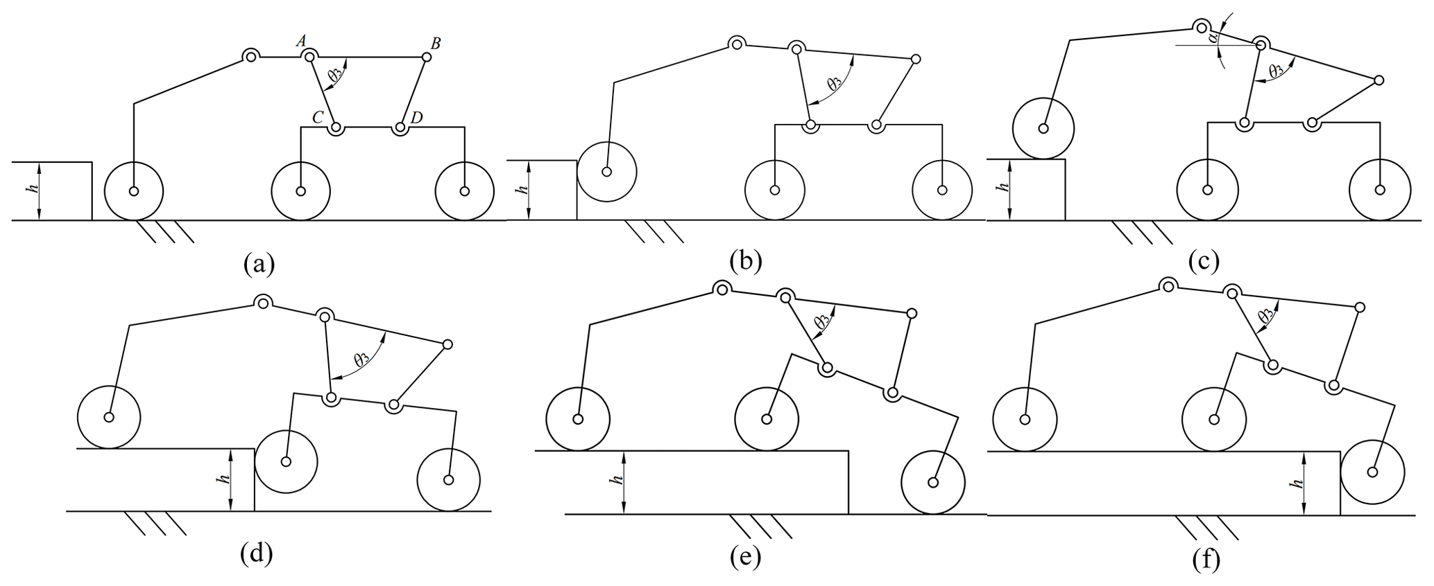
Firstly, the robot moves forward until the front walking wheels encounter the obstacle (Fig. 5a). Then, as the front walking wheels climb up the obstacle, the primary rockers are raised along the vertical surface of the obstacle (Fig. 5b). After the front walking wheels climb onto the obstacle, the robot keeps moving forward until the middle walking wheels contact the obstacle (Fig. 5c). Subsequently, as the middle walking wheels climb along the obstacle's vertical surface, the secondary rockers rotate accordingly (Fig. 5d). After the middle walking wheels climb onto the obstacle, the robot continues to move forward until the rear walking wheels contact the obstacle (Fig. 5e). Finally, under the traction of the front and middle walking wheels, the rear walking wheels of the robot climb over the obstacle (Fig. 5f).
For the robot to successfully climb an obstacle, its geometric posture must satisfy certain geometric and static conditions. In this section, the mathematical models of the geometric and static conditions will be established.
3.1 Geometric condition
The geometric obstacle-crossing height of the robot depends on the relative rotation angle between the primary and secondary rockers. In the rocker suspension, the relative motion range of the primary rocker and the secondary rocker is limited by the four-link mechanism connecting them, as shown in Fig. 6. During the obstacle-crossing process, θ3 continuously changes with the relative rotation between the primary and secondary rockers. When the lower connecting rod (C–D) and the right connecting rod (B–D) are collinear, the four-link mechanism is in the dead-centre position. In this position, there is interference between the right connecting rod (B–D) and the secondary rocker, and θ3 reaches its maximum value θ3max (Fig. 6a). When the left connecting rod (A–C) and the lower connecting rod (C–D) are collinear, the four-link mechanism is also in the dead-centre position. In this position, there is interference between the left connecting rod (A–C) and the secondary rocker, and the included angle θ3 is at its minimum value θ3min (Fig. 6b).
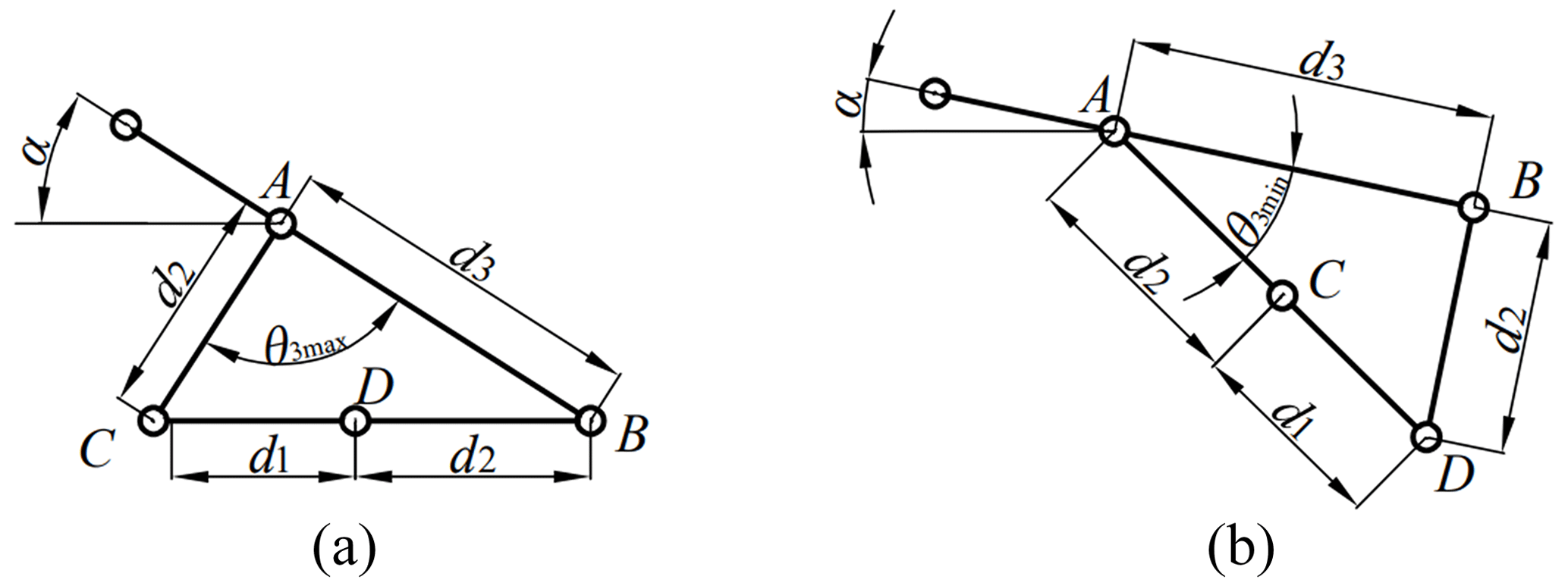
From Fig. 6, the value of θ3max and θ3min can be expressed as follows:
Furthermore, the geometric relationship between θ2 and θ3 can be expressed as follows:
During the obstacle-crossing process, the robot must always ensure that the included angle θ3 is less than θ3max and greater than θ3min. If this is not the case, it will be unable to continue to move forward due to interference within the four-link mechanism (A–B–C–D). Therefore, the geometric conditions that the robot needs to satisfy at any obstacle-crossing stages can be summarized as the following inequality:
In this section, an analysis of the robot's geometric posture at different obstacle-crossing stages is conducted to obtain an expression of the robot's obstacle-crossing height when the geometric conditions are satisfied.
At obstacle-crossing stage (b), as the front walking wheels of the robot climb up the obstacle, the included angle θ3 between the upper connecting rod (A–B) and the left connecting rod (A–C) will also continuously increase. Only when θ3 is always less than θ3max can the robot successfully enter obstacle-crossing stage (c). After the front walking wheels climb onto the obstacle, θ3 reaches its maximum value (as shown in Fig. 7).
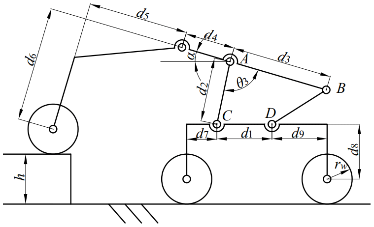
As shown in Fig. 7, the relationship between the obstacle height h and θ3 can be obtained as follows:
Because the middle and rear walking wheels are both on the horizontal ground, . Thus, Eq. (18) can be converted to
By drawing the curve of h as a function of θ3 through Eqs. (16) and (19), the geometric maximum obstacle height that the robot can climb up at stage (b) can be obtained.
At obstacle-crossing stage (d), the front walking wheels have climbed onto the upper surface of the obstacle. Under the traction of the front walking wheels, the middle walking wheels will climb upwards along the vertical surface of the obstacle. When the middle walking wheels are climbing along the vertical surface of the obstacle, the included angle θ3 will continue to decrease. The included angle θ3 must always remain greater than θ3min for the middle walking wheels to climb up the obstacle. After the middle walking wheels climb onto the obstacle, θ3 reaches its minimum value (as shown in Fig. 8).
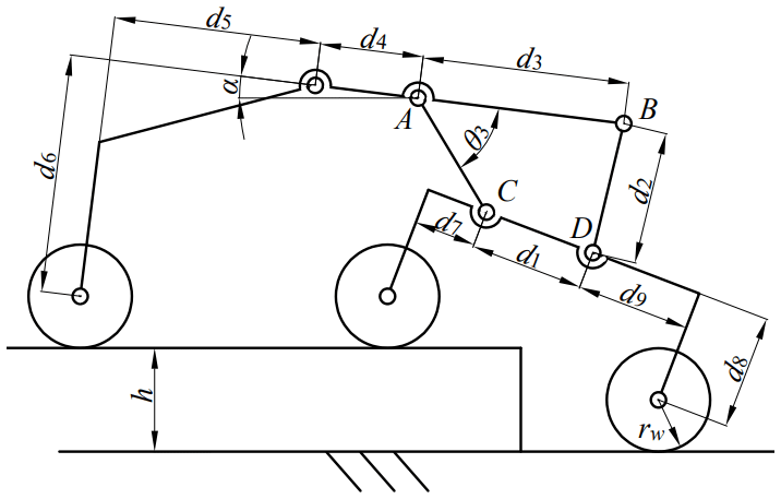
From Fig. 8, the mathematical relationship between α and θ2/ θ3 can be obtained as follows:
The obstacle height h can be expressed as follows:
By drawing the curve of h as a function of θ3 through Eqs. (16), (20) and (21), the geometric maximum obstacle height that the robot can climb up at stage (d) can be obtained.
At stage (f), as the rear walking wheels climb up the obstacle, the included angle θ3 gradually decreases, and there is no longer a risk of interference in the four-link mechanism (A–B–C–D). Hence, analysis of the robot is no longer carried out at this stage.
3.2 Static condition
In addition to the geometric conditions, the robot also needs to satisfy certain static conditions to cross the obstacle. From Fig. 5, it can be seen that the robot's three pairs of walking wheels will successively climb along the obstacle vertical surface during the obstacle-crossing process. Therefore, we conduct static analyses of the robot at these respective obstacle-crossing stages to obtain the static conditions that the robot needs to satisfy.
Figure 9 shows the static-force situation of the robot at obstacle-crossing stage (b). At this stage, the front walking wheels are climbing up the obstacle and the primary rocker will be raised along the vertical surface of the obstacle. Meanwhile, the middle and rear walking wheels continue to move forward to maintain the contact between the front walking wheels and the obstacle.
Because the mass of the primary and secondary rockers is far less than that of the robot's main body, their mass is ignored to simplify the analysis and calculation.
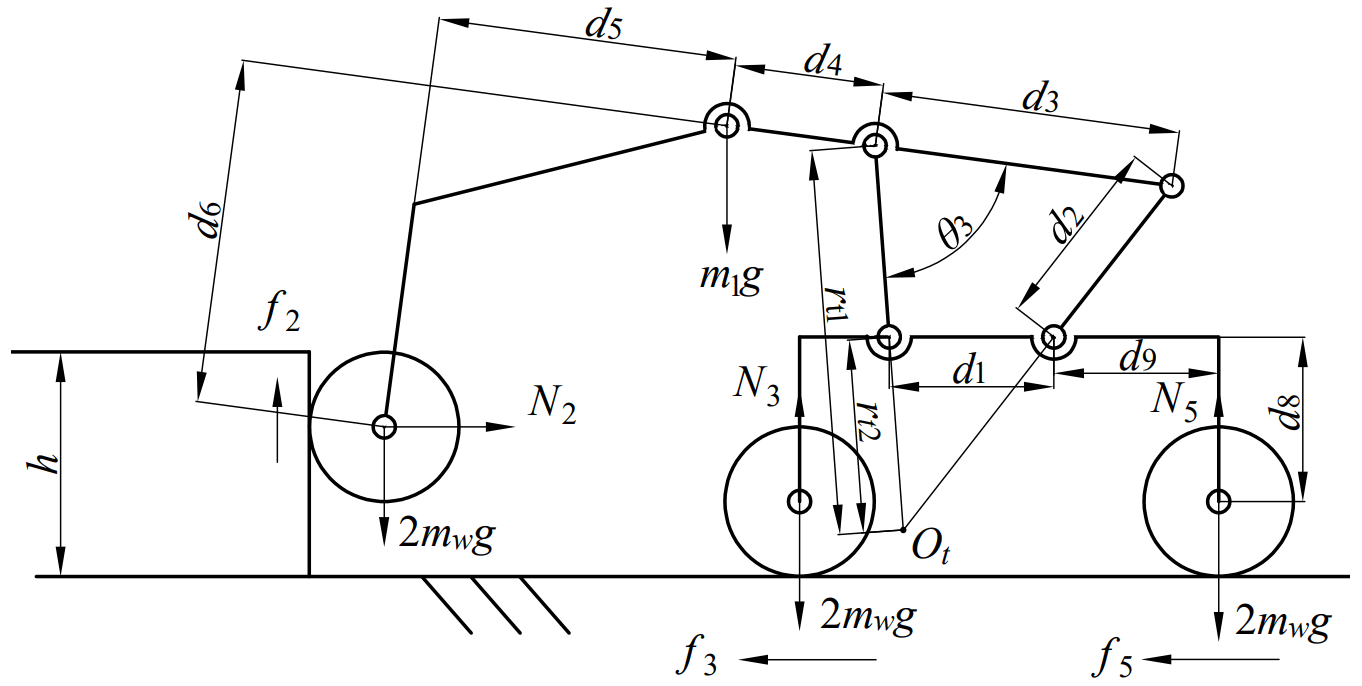
In Fig. 9, N2 represents the horizontal normal force exerted by the obstacle on the front walking wheels, f2 is the vertical frictional force between the obstacle and the front walking wheels, N3 and N5 represent the respective vertical support forces of the ground to the middle and rear walking wheels, f3 and f5 are the respective horizontal frictional forces between the ground and the middle and rear walking wheels, m1 represents the mass of the robot's main body, and mw and rw are the respective mass and radius of the walking wheel.
From Fig. 10, the static equilibrium equations of the robot in the horizontal and vertical directions can be derived as follows:
The balance equation of the torques applied to the primary rocker about point Ot can be obtained as follows:
In Eq. (23), there are
It is assumed that the sliding friction coefficient between the wheels and the ground and the obstacle surface is μ. At stage (b), if the front walking wheels can lift the primary rockers under the traction of sliding friction, the primary rockers can also be lifted when the pressure on the front walking wheels is large enough and the front walking wheels are subjected to static friction or rolling friction. Thus, we assume that the output torques of the front motors are large enough and that the front walking wheels rotate relative to the vertical surface of the obstacle. The middle and rear walking wheels are pure rolling on the ground without slipping. The frictional force on the front walking wheels is f2=μN2. Incorporating f2=μN2 into Eq. (23), the expression of N2 can be obtained as follows:
Because the included angle θ3 increases as the front walking wheels gradually climb upward, Eq. (25) represents the minimum pressure that the front walking wheels need to apply to the vertical surface of the obstacle as the pitch angle θ3 increases. To provide enough pressure, it is necessary to keep the middle and rear walking wheels from slipping, i.e. . Therefore, substituting Eq. (22) into , the static condition required for the robot to cross the obstacle at stage (b) can be expressed as the following inequality:
At stage (b), the robot can only lift the primary rocker without slipping the middle and rear wheels when it always satisfies inequality (26). Through Eq. (25), by drawing the curve of N2 as a function of θ3 and making a comparison with , the feasible region of the robot's geometric posture for which the robot can pass obstacle-crossing stage (b) will be obtained.
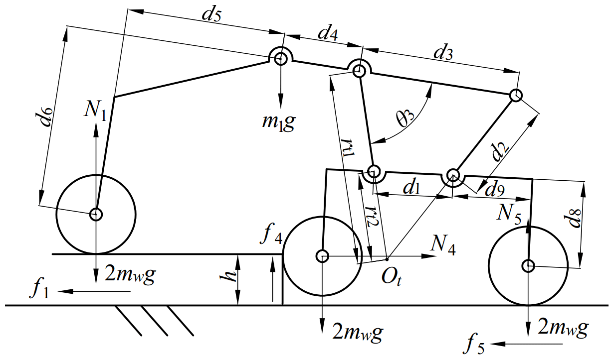
Figure 10 shows the static-force situation for the robot at obstacle-crossing stage (d). At this stage, the front walking wheels have climbed onto the upper surface of the obstacle, the middle walking wheels are climbing up the obstacle's vertical surface, and the secondary rockers are also raised. Meanwhile, the front and rear walking wheels continue moving forward to provide pressure between the middle walking wheels and the obstacle.
In Fig. 10, N1 represents the vertical support force of the obstacle to the front walking wheels, f1 is the horizontal frictional force between the obstacle and the middle walking wheels, N4 represents the horizontal normal force exerted by the obstacle on the middle walking wheels, and f4 is the vertical frictional force between the obstacle and the middle walking wheels. From Fig. 10, the static-force equilibrium equations of the robot in the horizontal and vertical directions and the torque equilibrium equations of the primary and secondary rockers about point Ot can be obtained as follows:
In Eqs. (29) and (30), there are
The height h of the obstacle that the front walking wheels have climbed onto can be expressed as follows:
Similarly, at stage (d), if the middle walking wheels can lift the secondary rockers under the traction of sliding friction, the secondary rockers can also be lifted when the pressure on the middle walking wheels is large enough and the middle walking wheels are subjected to static friction or rolling friction. We assume that the output torques of the middle motors are large enough and that the middle walking wheels rotate relative to the vertical surface of the obstacle. Therefore, the frictional force on the middle walking wheels is f4=μN4. We also assume that the output torques of the front and rear motors are the same and that both the front and rear walking wheels are pure rolling. Hence, the frictional forces applied to the front and rear walking wheels are equal – that is, f1=f5. Substituting f4=μN4, f1=f5, Eq. (27), Eq. (29) and Eq. (30) into Eq. (28), the expression of N4 can be obtained:
In Eq. (33), there are
As the middle walking wheels gradually climb upward, the included angle θ3 decreases. Equation (33) represents the minimum pressure that the middle walking wheels need to apply to the vertical surface of the obstacle to provide sufficient friction for the middle walking wheels to climb the obstacle. For the same reason, at stage (b), it is also necessary to keep the front and rear walking wheels from slipping at stage (d), i.e. . Therefore, the static condition required for the robot to cross the obstacle at stage (d) can be expressed as the following inequality:
Through Eq. (33), by drawing the curve of N4 as a function of θ3 and making a comparison with , the feasible region of the robot's geometric posture for which the robot can pass obstacle-crossing stage (d) will be obtained.
Figure 11 shows the static-force situation of the robot at obstacle-crossing stage (f). At this stage, the front and middle walking wheels have climbed onto the upper surface of the obstacle, under the traction of the front and middle walking wheels, and the rear walking wheels are climbing up the obstacle vertical surface.
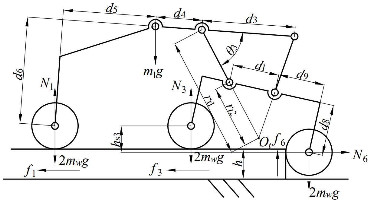
In Fig. 11, N6 represents the horizontal normal force exerted by the obstacle on the rear walking wheels, f6 represents the vertical frictional force between the obstacle and the rear walking wheels, N3 represents the vertical support force of the obstacle to the middle walking wheels, f3 represents the horizontal frictional force between the obstacle and the middle walking wheels at this stage, and represents the vertical distance between the middle and rear walking wheels. From Fig. 11, the static-force equilibrium equations of the robot in the horizontal and vertical directions and the torque equilibrium equations of the primary and secondary rockers about point Ot can be obtained as follows:
In Eq. (39), there are
The vertical distance between the middle and rear walking wheels can be expressed as follows:
At stage (f), we also assume that the rear walking wheels are subjected to sliding friction and that the output torques of the front and middle motors are the same. The front and middle walking wheels are pure rolling on the surface of the obstacle without slipping. Therefore, the frictional force on the rear walking wheels is f6=μN6 and the frictional forces applied to the front and rear walking wheels are equal, i.e. f1=f3. Substituting f6=μN6, f1=f3, Eq. (36), Eq. (38) and Eq. (39) into Eq. (37), the expression of N6 can be obtained:
Equation (42) represents the minimum pressure that the rear walking wheels need to apply to the vertical surface of the obstacle. At stage (f), the front and middle walking wheels must maintain pure rolling to provide sufficient pressure for the rear walking wheels to climb the obstacle, i.e. . Hence, the static condition for obstacle crossing for the proposed robot at stage (f) can be expressed as the following inequality:
Through Eq. (42), by drawing the curve of N6 as a function of θ3 and making a comparison with , the feasible region of the robot's geometric posture for which the robot can pass obstacle-crossing stage (f) will be obtained.
In Sect. 3, the geometric and static conditions that the proposed robot needs to satisfy to cross a vertical obstacle have been obtained via mathematical analysis. In terms of the geometric conditions, the included angle θ3 of the robot's four-link mechanism must always satisfy inequality (17), i.e. . In terms of the static conditions, the robot has to satisfy inequalities (26), (35), and (43) at obstacle-crossing stages (b), (d) and (f) respectively. In addition to the dimensions of each part of the robot, especially that of the four-link mechanism (A–B–C–D), whether the robot can satisfy the obstacle-crossing conditions also depends on the friction between the wheels and the ground as well as the height of obstacles.
In this section, numerical simulations will be conducted to discuss whether the robot can climb obstacles, and the robot's maximum obstacle-crossing height that satisfies the geometric and static conditions will be obtained. The geometric and mass parameters of the robot are assigned as follows: d1=110 mm, d2=128 mm, d3=200 mm, d4=100 mm, d5=200 mm, d6=230 mm, d7=60 mm, d8=110 mm, d9=110 mm, rw=50 mm, m1=8 kg and mw=1 kg. It is assumed that the robot performs exploration missions on the Moon. Thus, the gravitational acceleration g is taken as 1.63 N kg−1.
4.1 Geometric obstacle-crossing capability simulations
It can be seen from inequality (17) that the value range of θ3 geometrically restricts the robot's obstacle-crossing height. By incorporating the robot's geometric parameters in Eqs. (14) and (15), the value range of θ3 can be obtained as follows:
Moreover, by solving the implicit function of Eq. (16) using MATLAB®, the relation curve between θ2 and θ3 can be obtained (as shown in Fig. 12).
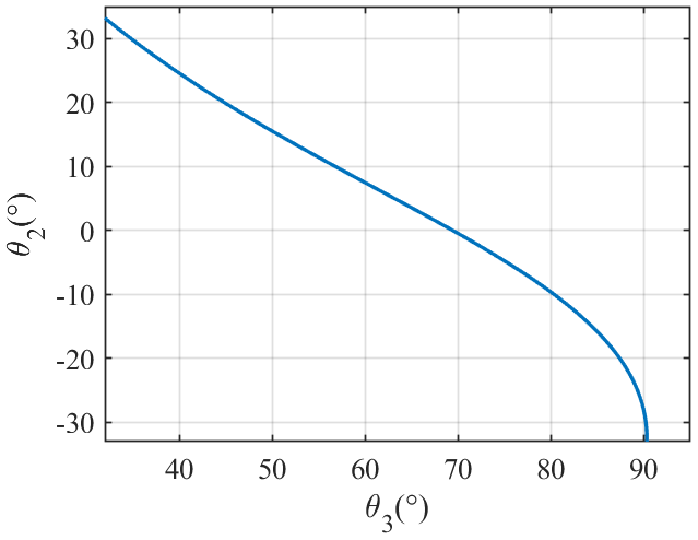
It can be seen from Fig. 12 that θ2 decreases continuously as θ3 increases when θ3 is within the range of .
By substituting the values of θ2 and θ3 into Eqs. (19), (20) and (21) and drawing the curves of the obstacle height h that the robot can climb as a function of θ3 at stages (c) and (e), we can get the relationship between the robot's geometric posture and its obstacle-crossing height (as shown in Fig. 13).
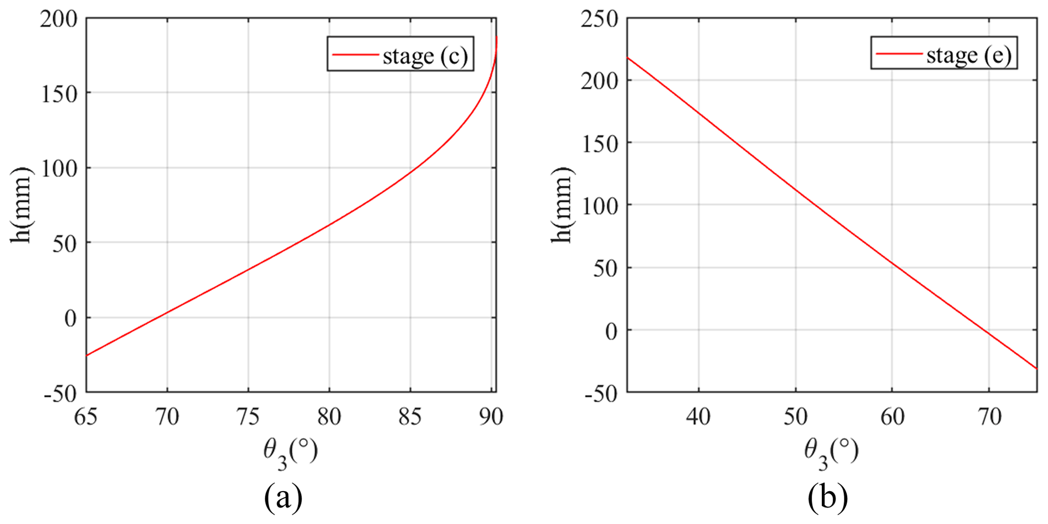
Figure 13Curves of the robot's obstacle-crossing height h as a function of θ3: (a) the obstacle height h that the robot can climb at stage (c) in Fig. 5; (b) the obstacle height h that the robot can climb at stage (e) in Fig. 5.
From Fig. 13, it can be seen that the height h of the obstacle that the robot can climb at stage (c) gradually increases with an increase in θ3. Moreover, when θ3 is equal to θ3max (90.3299°), the maximum obstacle-crossing height satisfying the geometric conditions is 185.2 mm. At stage (e), as θ3 decreases, the obstacle height that the robot can climb onto gradually increases. When θ3 is equal to θ3min (32.5555°), the robot's maximum obstacle-crossing height satisfying the geometric conditions is 218.2 mm.
4.2 Static obstacle-crossing capability simulations
The static conditions that the robot needs to satisfy are different at different obstacle-crossing stages. Thus, we carried out a simulation for each stage in turn. By substituting the geometric and mass parameters into Eqs. (25), (33) and (42) and making the corresponding curves, the feasible region of θ3 that the robot can climb over the obstacle with at different stages can be obtained.
At stage (b), according to Eq. (25) and inequality (26), besides the geometric parameters, whether the robot can cross the obstacle also depends on the friction coefficient μ. Because the middle and rear walking wheels are both on the horizontal ground, in Eq. (25). Hence, by substituting the robot's parameters and into Eq. (25), the curves of N2 as a function of θ3 under different friction coefficients μ can be drawn (as shown in Fig. 14).
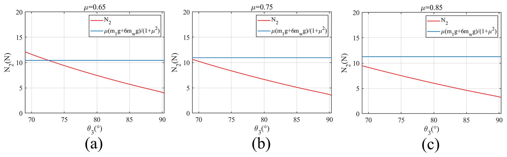
Figure 14Curves of N2 as a function of θ3 at stage (b) in Fig. 5 under different friction coefficients: (a) the curve of N2 as a function of θ3 at stage (b) in Fig. 5 under the friction coefficient μ=0.65; (b) the curve of N2 as a function of θ3 at stage (b) in Fig. 5 under the friction coefficient μ=0.75; (c) the curve of N2 as a function of θ3 at stage (b) in Fig. 5 under the friction coefficient μ=0.85.
It can be seen from Fig. 14 that the pressure that the front walking wheels' of the robot needs to apply to the obstacle decreases gradually as the angle θ3 increases (i.e. as the front walking wheels climb upward along the obstacle). From Fig. 12, we can know that θ3 is equal to 69.44° when the robot is on the ground (i.e. ). Thus, as long as N2 is always less than μ when θ3 is greater than 69.44°, it can be considered that the robot can smoothly pass through stage (b). However, in Fig. 14, when the friction coefficient μ is equal to 0.65, the front walking wheels cannot climb along the vertical surface of the obstacle. Because the pressure N2 is larger than μ when θ3 is less than 72.59°, the middle and rear walking wheels slip and cannot provide enough propulsive force. When the friction coefficient μ is equal to 0.75 and 0.85, the robot can pass stage (b) successfully. Therefore, it can be concluded that a larger the friction coefficient μ is more advantageous with respect to the robot passing obstacle-crossing stage (b).
Compared with the soil on the Earth, lunar soil is drier (Sun et al., 2008). Moreover, there are more irregular structures, such as corners and saw teeth, on the surface of lunar soil particles (Zheng et al., 2004). Therefore, we assume that the friction coefficient μ between the robot's wheels and the lunar surface is 0.75 (Li et al., 2009), and this setting will continue to be used in the following.
Stage (d) is the key step for the robot to cross the obstacle. The height of the obstacle determines whether the robot can successfully pass stage (d). After the front walking wheels climb onto the obstacle upper surface, the pitch angle α of the robot's main body increases, which shortens the instantaneous rotation radius of the secondary rockers and is not conducive to the middle walking wheels climbing onto the obstacle.
Hence, we analyse the force situation with respect to the robot when its middle walking wheels just leave the ground, in order to explore whether the middle walking wheels can leave the ground and climb upwards. At this time, the main body's pitch angle α is equal to −θ2. By substituting and μ=0.75 into Eq. (33), we can draw the curve of N4 as a function of θ3 (as shown in Fig. 15a); concurrently, by incorporating into Eq. (32), we can obtain the curve of the front walking wheels' obstacle-crossing height as a function of θ3 when (as shown in Fig. 15b).
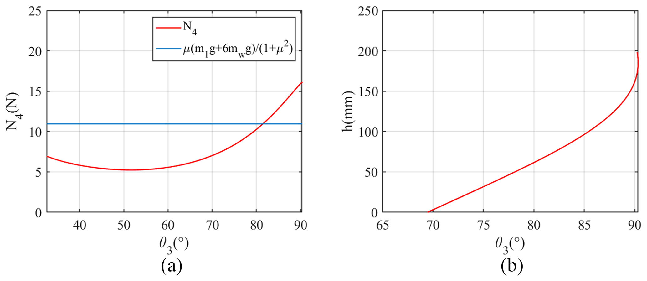
Figure 15Obstacle-crossing situation of the robot at stage (d) in Fig. 5 (): (a) curve of N4 as a function of θ3 at stage (d) in Fig. 5 (); (b) curve of h as a function of θ3 at stage (d) in Fig. 5 ().
Only when the obstacle's normal force N4 satisfies inequality (35) can the middle walking wheels leave the ground and climb the vertical surface of the obstacle. It can be seen from Fig. 15a that θ3 must be less than 81.48° for the robot to satisfy the static condition of the middle walking wheels climbing the obstacle. In Fig. 15b, it can be seen that, when θ3 reaches 81.48°, the height of the obstacle that the front walking wheels have climbed onto is 71 mm.
From Fig. 15a and b, we can see that, when the height of the obstacle is less than 71 mm, the middle walking wheels can climb along the vertical surface of the obstacle away from the ground at stage (d). However, further discussion is still needed to determine whether the robot can consistently satisfy inequality (35) during the climbing process of the middle walking wheels.
Hence, by substituting h=71 mm into Eqs. (32) and (33), the curve of N4 as a function of θ3 when the middle walking wheels are climbing up the obstacle can be obtained (as shown in Fig. 16).
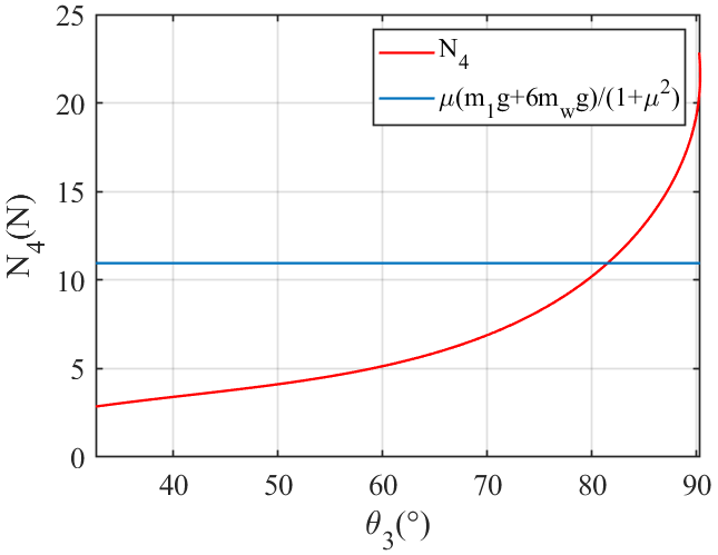
Figure 16Curve of N4 as a function of θ3 when the middle walking wheels are climbing up the obstacle.
When the middle walking wheels are climbing an obstacle, θ3 decreases gradually. From Fig. 16, we see that N4 decreases as θ3 decreases during the climbing process of the middle walking wheels. It can be found that N4 always satisfies inequality (35) when θ3 is less than 81.48°, which means that the middle walking wheels can climb onto an obstacle with a height of 71 mm. We also believe that the middle walking wheels can climb onto an obstacle as long as the height of the obstacle is less than 71 mm. Therefore, the maximum obstacle-crossing height of the robot satisfying the static condition is 71 mm at obstacle-crossing stage (d).
At stage (f), the robot's front and middle walking wheels have climbed onto the upper surface of the obstacle. During the climbing process of the rear walking wheels, the obstacle's normal force N6 must always satisfy inequality (43). Thus, by substituting μ=0.75 into Eq. (42), the curve of N6 as a function of θ3 at stage (f) can be drawn (as shown in Fig. 17a); simultaneously, we can draw the curve of as a function of θ3 (as shown in Fig. 17b).
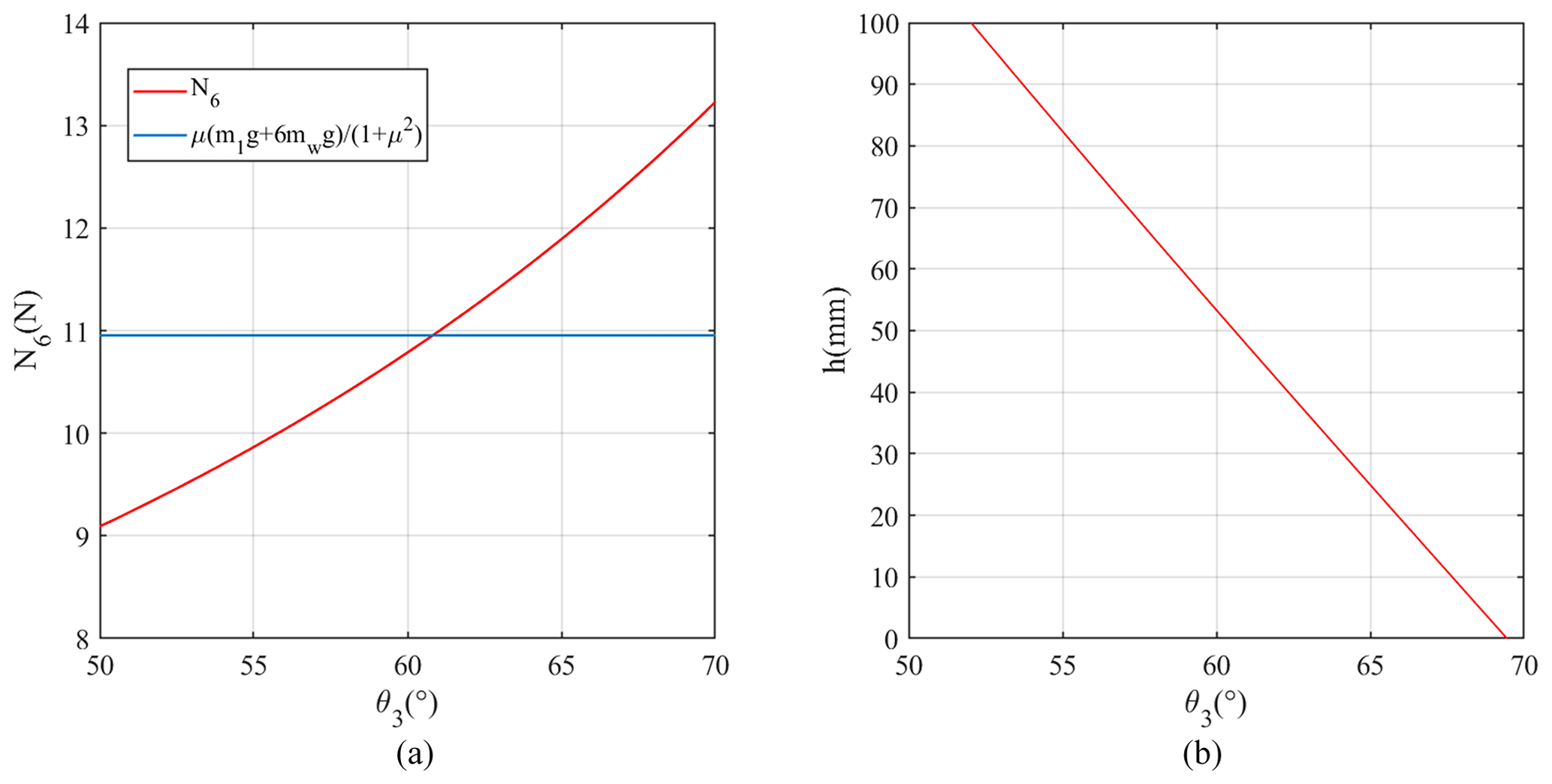
Figure 17Obstacle-crossing situation of the robot at stage (f) in Fig. 5: (a) curve of N6 as a function of θ3 at stage (f) in Fig. 5; (b) curve of as a function of θ3 at stage (f) in Fig. 5.
As the rear wheels climb upwards along the vertical surface of the obstacle, θ3 gradually increases and the vertical distance between the middle and rear walking wheels gradually decreases. From Fig. 17a, it can be seen that inequality (43) is only satisfied when θ3 is less than 60.82°. In Fig. 17b, we find that is equal to 48.7 mm when θ3= 60.82°, which means that the robot no longer meets the obstacle-crossing static conditions when is less than 48.7 mm.
However, when is shorter than the radius of the wheels (50 mm) during the actual obstacle-crossing process, the static-force situation of the robot in Fig. 11 is no longer realistic, and it can be considered that the rear walking wheels can climb onto the upper surface of the obstacle. Moreover, because the minimum value 48.7 mm of is shorter than the wheel radius rw, it can be considered that the rear walking wheels can climb onto the obstacle, and the robot can pass obstacle-crossing stage (f).
In this section, through numerical simulations, we have explored the obstacle-crossing capability of the robot at different obstacle-crossing stages using geometry and statics. From a geometric perspective, restricted by the motion range of the four-link mechanism (A–B–C–D), the maximum obstacle-crossing height of the robot at obstacle-crossing stages (c) and (e) are 182.5 and 218.2 mm respectively. From a statistical perspective, whether the robot can pass stage (d) determines its maximum obstacle-crossing height. The robot's maximum obstacle-crossing height at stage (d) is 71 mm. In addition, the friction coefficient μ between the wheels and the ground must be large enough for the robot to lift the primary rocker along the obstacle during obstacle-crossing stage (b). Furthermore, at stage (f), only when the vertical distance between the middle and rear walking wheels is equal to the radius of the wheel (i.e. the robot still satisfies inequality 43) can the rear walking wheels climb onto the upper surface of the obstacle.
In the previous sections, the mechanical structure of the proposed robot has been introduced, and the obstacle-crossing capability of the proposed robot has been analysed through modelling and simulations.
In this section, a prototype of the proposed robot is developed (as shown in Fig. 18). The structural parameters and technical specifications of the prototype are listed in Table 1. The geometric size of the prototype is 789.5 mm × 454 mm × 595 mm (length × width × height), and it has a total mass of 40 kg. The robot's maximum forward speed is about 5 m s−1, while its steering speed is approximately 24 ° s−1. Relying on the four-link rocker suspensions on both sides, the robot can travel on uneven grassland (Fig. 18b). A differential bevel gear group and an active pitch control device are located inside robot; together, these form the differential pitching device (Fig. 18c). There is also a steering device above the respective front and rear wheels of the robot (Fig. 18d). By controlling the directions of the front and rear walking wheels through the steering devices, the robot can achieve in situ differential steering (Fig. 18e).
Table 1Structural parameters and technical specifications of the prototype.
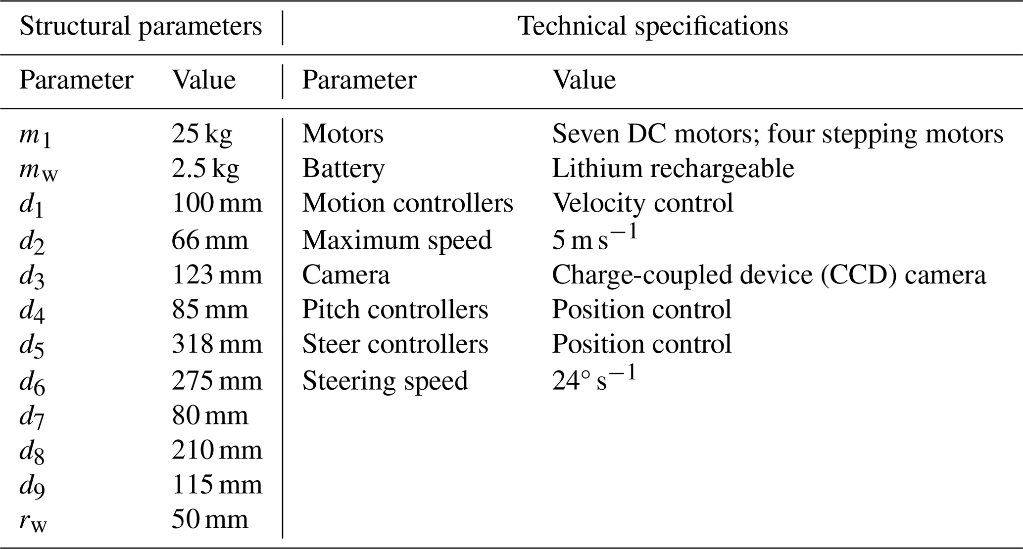
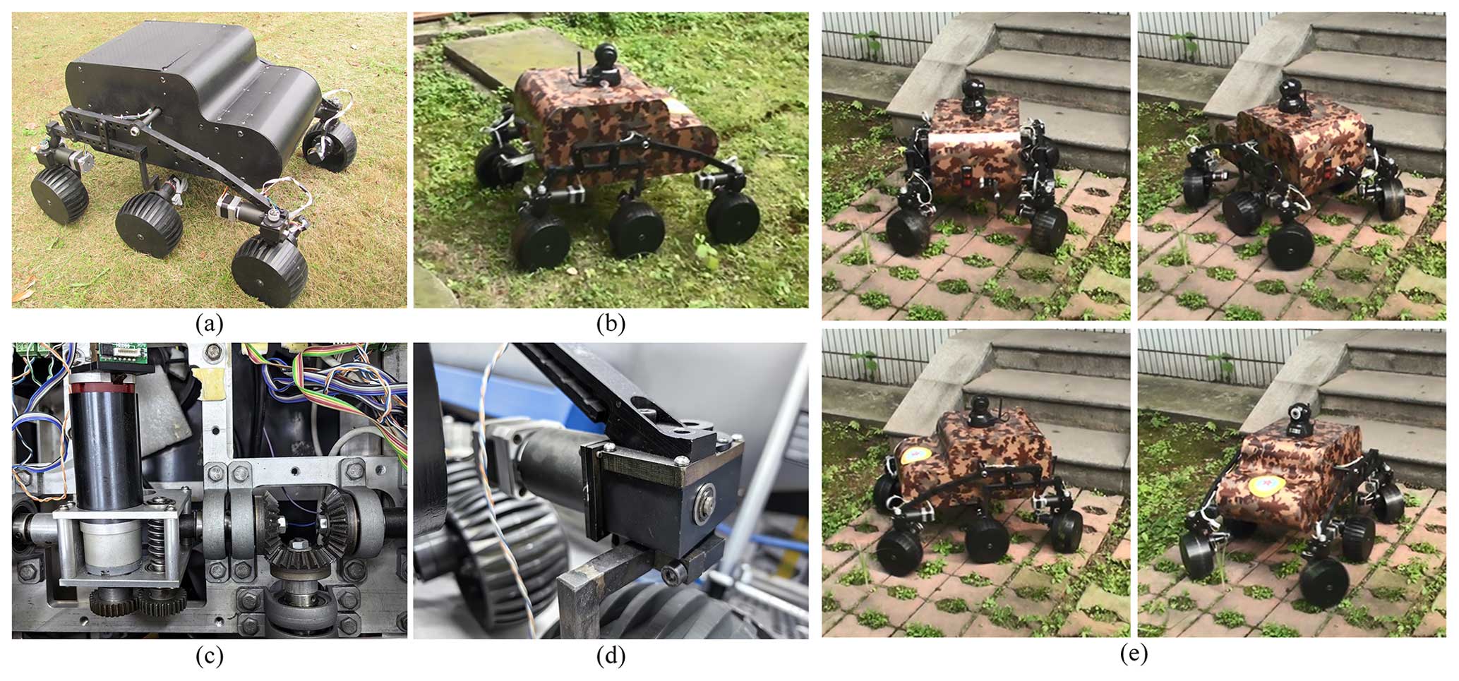
Figure 18Physical prototype of the proposed robot: (a) the appearance of the robot; (b) the robot travelling on the uneven grassland; (c) the differential pitching device in the robot; (d) the steering device; (e) the robot using in situ differential steering.
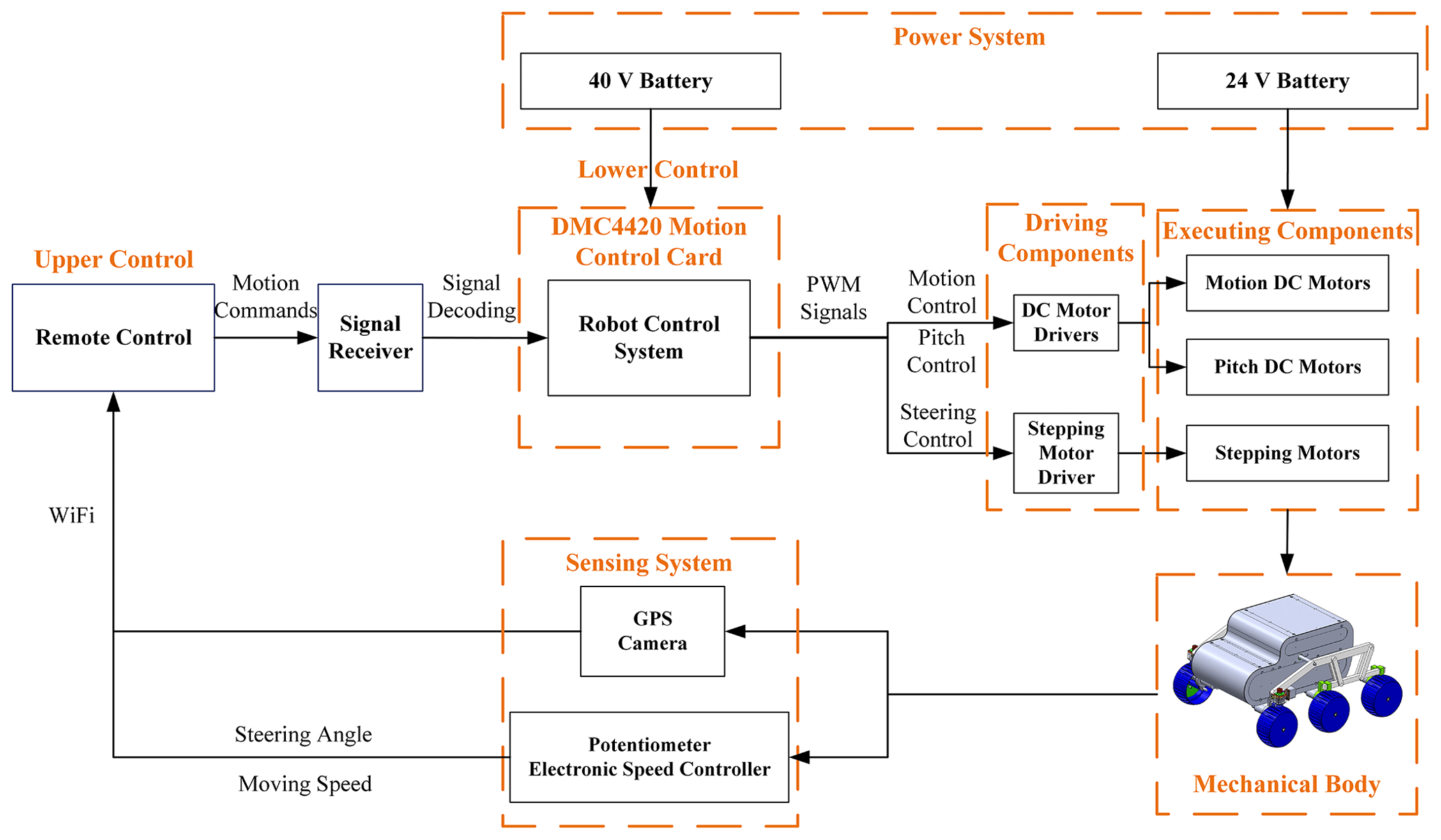
The robot's mechatronic system is shown in Fig. 19. The mechatronic system is composed of six parts: the control system, the sensing system, the driving components, the power system, the executing components and the robot's mechanical body. The robot's control system is composed of two controllers: (1) a low-level controller, which is a DMC4420PC104 Motion Control Card (Leadshine, China), and (2) an upper controller, which is the remote control held by the operator. The motion commands sent by the upper controller are decoded by the signal receiver and then transmitted to the robot's control system. After receiving the decoded signals, the control system sends the PWM signals and controls the 11 motors (7 DC motors and 4 stepping motors) of the robot through the driving components. Driven by the executing components, the robot moves and then feeds back the its status information (speed, steering angle, battery remaining capacity, GPS and so on) and the camera's view to the remote control. The DMC4420 Motion Control Card is supplied electricity by a 40 V battery, and the executing components are powered by a 24 V battery.
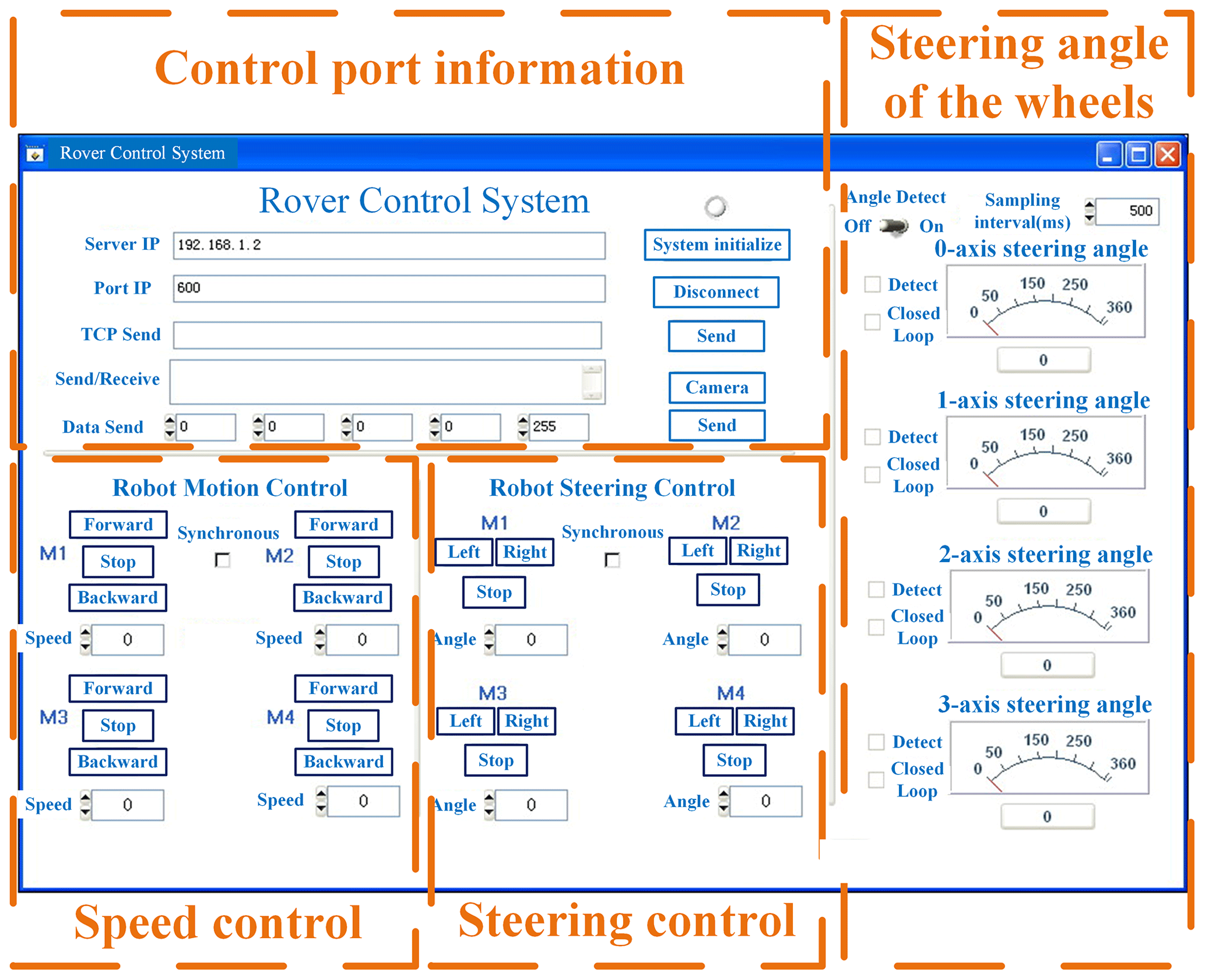
The robot's status information uploaded by the sensing system is visible on the handheld remote control, as shown in Fig. 20 (this software has been independently developed by us). According to the information, the operator can control the motion of the robot by pulling the rocking bars.
This robot is a principal prototype that has been used to verify the feasibility of the design scheme and robot control methods. In the future, a prototype that is consistent with the calculated design parameters will be developed. Following this, a series of experiments, such as traversing a sandy landscape and climbing steps, will be carried out to verify the obstacle-crossing capability and terrain adaptability of the robot.
This paper proposes a design concept for a six-wheeled rocker-suspension planetary exploration rover. Through a differential pitching device, this robot can passively or actively maintain its main body's balance in motion. The proposed robot also has a four-link rocker suspension, which can increase the instantaneous rotation radius of the rockers and improve the obstacle-crossing capability of the robot.
In this paper, the mechanical design of the proposed robot has been presented first. By dividing the robot's obstacle-crossing process into six stages, obstacle-crossing models for the robot were established. The geometric and static conditions for obstacle-crossing were then derived and demonstrated for the robot. Through numerical simulations, the obstacle-crossing capability of the robot was analysed, and the maximum obstacle-crossing height of the robot was calculated using both geometry and statics. Finally, a prototype of the proposed robot was developed, and the mechatronic system of the robot was introduced.
Compared with other traditional planetary rovers, this robot can increase the instantaneous turning radius of its rockers when encountering obstacles via a four-link mechanism connecting the primary and secondary rockers; this means that the robot can climb over obstacles above the radius of the wheels without a complex perception and control strategy. The maximum obstacle-crossing height of the robot is 71 mm, and the obstacle-crossing height transformation ratio – the ratio of the maximum obstacle-crossing height to the wheel radius (Mertyüz et al., 2020) – reaches 1.42. Using the differential pitching device, the robot can adapt to terrain fluctuation via both active and passive modes. In the passive adaptation mode, the influence of terrain fluctuations on the pitch angle of the robot's main body will be reduced. In the active control mode, the robot can actively adjust the pitch angle of its main body to a specific angle according to the task requirements.
This robot provides a feasible design scheme for future planetary exploration rovers that can improve the obstacle-crossing capability and terrain adaptability of rocker-suspension robots without a complex control strategy or additional mechanical devices.
In addition to verifying the robot's performance through more experiments, further research will focus on optimizing the robot's structural parameters to maximize its obstacle-crossing capability.
| Structural parameters | |
| α | The pitch angle of the main body relative to the ground |
| The pitch angle of the left primary rocker relative to the ground | |
| The pitch angle of the right primary rocker relative to the ground | |
| The instantaneous rotation radius of the primary rocker | |
| The instantaneous rotation radius of the secondary rocker | |
| d1 | The length of connecting rod C–D in the four-link mechanism |
| d2 | The length of connecting rods B–D and A–C in the four-link mechanism |
| d3 | The length of connecting rod A–B in the four-link mechanism |
| d4 | The length between the point A and the main body's CoM (centre of mass) |
| d5 | The horizontal length between the front walking wheels and the main body's CoM |
| d6 | The height of the rocker suspension |
| d7 | The horizontal length between the middle walking wheels and point C |
| d8 | The height of the secondary rocker |
| d9 | The horizontal length between the rear walking wheels and point D |
| The number of teeth in bevel gear 1′ | |
| The number of teeth in bevel gear 2′ | |
| The number of teeth in bevel gear 3′ | |
| zw | The number of worm's heads |
| zwg | The number of worm's gear teeth |
| δl | The rotation angle of the left rocker connecting shaft relative to the device base |
| δr | The rotation angle of the right rocker connecting shaft relative to the device base |
| The rotation angle of bevel gear 1′ relative to the device base | |
| The rotation angle of bevel gear 2′ relative to the device base | |
| The rotation angle of bevel gear 3′ relative to the device base | |
| δw | The rotation angle of the worm relative to the device base |
| δwg | The rotation angle of the worm gear relative to the device base |
| δm | The rotation angle of the DC motor relative to the device base |
| O0{X0,Y0} | The ground-fixed coordinate frame |
| O1{X1,Y1} | The robot's body coordinate frame |
| (a, b) | The coordinate of origin O1 expressed in the ground-fixed coordinate frame |
| The value of the rotation torque that N2 applies to the primary rocker in Fig. 3b | |
| θ3 | The included angle between the upper link (A–B) and the front link (A–C) |
| θ2 | The included angle between the upper link (A–B) and the lower link (A–C) |
| h | The height of the obstacle |
| rw | The radius of the walking wheel |
| m1 | The mass of the robot's main body |
| mw | The mass of the walking wheel |
| Ot | The instantaneous centre of the rotation of the rockers |
| The vertical distance between the middle and rear walking wheels at stage (d) | |
| Static parameters | |
| N1 | The vertical support force of the obstacle to the front walking wheels |
| N2 | The horizontal normal force exerted by the obstacle on the front walking wheels |
| N3 | The vertical support force of the ground, stage (b), or obstacle, stage (f), to the middle walking wheels |
| N4 | The horizontal normal force exerted by the obstacle on the middle walking wheels |
| N5 | The support force of the ground to the rear walking wheels |
| N6 | The horizontal normal force exerted by the obstacle on the rear walking wheels |
| f1 | The horizontal frictional force between the obstacle and the middle walking wheels |
| f2 | The vertical frictional force between the obstacle and the front walking wheels |
| f3 | The horizontal frictional force between the ground, stage (b), or obstacle, stage (f), and the middle walking wheels |
| f4 | The vertical frictional force between the obstacle and the middle walking wheels |
| f5 | The horizontal frictional force between the ground and the rear walking wheels |
| f6 | The vertical frictional force between the obstacle and the front walking wheels |
| μ | The sliding friction coefficient between the wheels and the ground and the obstacle surface |
| Mathematical symbols | |
| E1 | |
| E2 | |
| E3 | |
| E4 | |
| E5 | |
| E6 | |
| E7 | |
| E8 | |
| E9 | |
| E10 | |
| E11 | |
| E12 | d6sin α+d5cos α |
| E13 | |
| E14 | |
| E15 | |
The code and data relevant to this work are available from the corresponding author upon reasonable request.
ZS carried out the experiments and wrote the original draft; ZL contributed to the conception of the study and designed the experiments; HX helped revise the paper and gave some advice on robot design. All authors have read and agreed to the published version of the paper.
The contact author has declared that none of the authors has any competing interests.
Publisher’s note: Copernicus Publications remains neutral with regard to jurisdictional claims made in the text, published maps, institutional affiliations, or any other geographical representation in this paper. While Copernicus Publications makes every effort to include appropriate place names, the final responsibility lies with the authors.
The authors acknowledge financial support from the National Natural Science Foundation of China.
This research has been supported by the National Natural Science Foundation of China (grant no. 52175069).
This paper was edited by Engin Tanık and reviewed by Volkan Parlaktaş and two anonymous referees.
Aoki, T., Murayama, Y., and Hirose, S.: Development of a Transformable Three-wheeled Lunar Rover: Tri-Star IV, J. Field Robot., 31, 206–223, https://doi.org/10.1002/rob.21482, 2013.
Arm, P., Zenkl, R., Barton, P., Beglinger, L., Dietsche, A., Ferrazzini, L., Hampp, E., Hinder, J., Huber, C., Schaufelberger, D., Schmitt, F., Sun, B., Stolze, B., Kolvenbach, H., and Hutter, M.: SpaceBok: A Dynamic Legged Robot for Space Exploration, in: 2019 International Conference on Robotics and Automation (ICRA), Montreal, Canada, 20–24 May 2019, IEEE, 6288–6294, https://doi.org/10.1109/ICRA.2019.8794136, 2019.
Bartsch, S.: Development, Control, and Empirical Evaluation of the Six-Legged Robot SpaceClimber Designed for Extraterrestrial Crater Exploration, Künstliche Intelligenz, 28, 127–131, https://doi.org/10.1007/s13218-014-0299-y, 2014.
Bartsch, S., Birnschein, T., Cordes, F., Kühn, D., Kampmann, P., Hilljegerdes, J., Planthaber, S., Römmermann, M., and Kirchner, F.: SpaceClimber: Development of a Six-Legged Climbing Robot for Space Exploration, in: ISR 2010 (41st International Symposium on Robotics) and ROBOTIK 2010 (6th German Conference on Robotics), Munich, Germany, 7–9 June 2010, VDE, 1265–1272, 2010.
Bogue, R.: Robots for space exploration, Ind. Robot, 36, 323–328, https://doi.org/10.1108/01439911211227872, 2012.
Bruzzone, L. and Quaglia, G.: Review article: locomotion systems for ground mobile robots in unstructured environments, Mech. Sci., 3, 49–62, https://doi.org/10.5194/ms-3-49-2012, 2012.
Cabrol, N. A., Bettis III, E. A., Glenister, B., Chong, G., Herrera, C., Jensen, A., Pereira, M., Stoker, C. R., Grin, E. A., Landheim, R., Thomas, G., Golden, J., Saville, K., Ludvigson, G., and Witzke, B.: Nomad Rover Field Experiment, Atacama Desert, Chile: 2. Identification of paleolife evidence using a robotic vehicle: Lessons and recommendations for a Mars sample return mission, J. Geophys. Res.-Planet., 106, 7807–7815, https://doi.org/10.1029/1999JE001181, 2001a.
Cabrol, N. A., Chong-Diaz, G., Stoker, C. R., Gulick, V. C., Landheim, R., Lee, P., Roush, T. L., Zent, A. P., Herrera Lameli, C., Jensen Iglesia, A., Pereira, Arrerondo, M., Dohm, J. M., Keaten, R., Wettergreen, D., Sims, M. H., Schwher, K., Bualat, M. G., Thomas, H. J., Zbinden, E., Christian, D., Pedersen, L., Bettis III, A., Thomas, G., and Witzke, B.: Nomad Rover Field Experiment, Atacama Desert, Chile: 1. Science results overview, J. Geophys. Res.-Planet., 106, 7785–7806, https://doi.org/10.1029/1999JE001166, 2001b.
Cordes, F., Dettmann, A., and Kirchner, F.: Locomotion modes for a hybrid wheeled-leg planetary rover, in: 2011 IEEE International Conference on Robotics and Biomimetics, Karon Beach, Thailand, 7–11 December 2011, IEEE, Vol. 4, https://doi.org/10.1109/ROBIO.2011.6181694, 2011.
Dirk, S. and Frank, K.: The Bio-Inspired SCORPION Robot: Design, Control & Lessons Learned, Künstliche Intelligenz, 28, 127–131, https://doi.org/10.5772/5081, 2014.
Excell, J.: CRAWL SPACE: A diminutive four-legged robot looks set to become the UK's first visitor to the moon, Engineer, 301, 30–31, 2021.
Harrison, D. A., Ambrose, R., Bluethmann, B., and Junkin, L.: Next Generation Rover for Lunar Exploration, in: 2008 IEEE Aerospace Conference, Big Sky, MT, USA, 1–8 March 2008, IEEE, 1–14, https://doi.org/10.1109/AERO.2008.4526234, 2008.
Herkenhoff, B., Lanctot, S., and Hassanalian, M.: Design and Prototyping of Bioinspired Jumping Robot for Lunar Exploration, ASCEND, Las Vegas, Nevada, 15–17 November 2021, AIAA 2021-4145, https://doi.org/10.2514/6.2021-4145, 2021.
Kim, D., Hong, H., Kim, H. S., and Kim, J.: Optimal design and kinetic analysis of a stair-climbing mobile robot with rocker-bogie mechanism, Mech. Mach. Theory, 50, 90–108, https://doi.org/10.1016/j.mechmachtheory.2011.11.013, 2012.
Kolvenbach, H., Breitenstein, M., Gehring, C., and Hutter, M.: Scalability analysis of legged robots for space exploration, in: 68th International Astronautical Congress (IAC), Adelaide, Australia, 25–29 September 2017, IAF, https://doi.org/10.3929/ethz-b-000183684, 2017.
Kozma, R., Hunstberger, T., Aghazarian, H., and Freeman, W. J.: Implementing intentional robotics principles using SSR2K platform, in: IEEE/RSJ International Conference on Intelligent Robots & Systems, San Diego, CA, USA, 29 October–2 November 2007, IEEE, https://doi.org/10.1109/IROS.2007.4399490, 2007.
Kozma, R., Huntsberger, T., Aghazarian, H., Tunstel, E., Ilin, R., and Freeman, W.: Intentional Control for Planetary Rover SRR, Adv. Robotics, 22, 1309–1327, https://doi.org/10.1163/156855308X344846, 2008.
Li, Y., Li, J., Zou, M., and Ren, L.: Simulation of Traction Ability of Lunar Rover with Different Mechanics of Lunar Soil, Transactions of the Chinese Society for Agricultural Machinery, 40, 1–4, ISSN 1000-1298, 2009.
Lindemann, R. A. and Voorhees, C. J.: Mars Exploration Rover mobility assembly design, test and performance, in: 2005 IEEE International Conference on Systems, Man and Cybernetics, Waikoloa, HI, USA, 12 October 2005, IEEE, Vol. 1, https://doi.org/10.1109/ICSMC.2005.1571187, 2005.
Lordos, G., Brown, M. J., Latyshev, K., Liao, A., Shah, S., Meza, C., Bensche, B., Cao, C., Chen, Y., Miller, A. S., Mehrotra, A., Rodriguez, J., Mokkapati, A., Cantu, T., Sapozhnikov, K., Rutledge, J., Trumper, D., Kim, S., de Weck, O., Hoffman, J., and Chun, W.: WORMS: Field-Reconfigurable Robots for Extreme Lunar Terrain, in: 2023 IEEE Aerospace Conference, Big Sky, MT, USA, 4–11 March 2023, IEEE, 1–21, https://doi.org/10.1109/AERO55745.2023.10115833, 2023.
Meghdari, A., Pishkenari, H. N., Gaskarimahalle, A. L., Mahboobi, S. H., and Karimi, R.: A Novel Approach for Optimal Design of a Rover Mechanism, J. Intell. Robot. Syst., 44, 291–312, https://doi.org/10.1007/s10846-005-9013-5, 2005.
Mertyüz, R., Tanyldz, A. K., Taşar, B., Tatar, A. B., and Yakut, O.: FUHAR: A transformable wheel-legged hybrid mobile robot, Robot. Auton. Syst., 133, 103627, https://doi.org/10.1016/j.robot.2020.103627, 2020.
Roehr, T. M., Cordes, F., and Kirchner, F.: Reconfigurable integrated multirobot exploration system (RIMRES): Heterogeneous modular reconfigurable robots for space exploration (Article), J. Field Robot., 31, 3–34, https://doi.org/10.1002/rob.21477, 2014.
Sharafa, O., Amiria, S., AlDhafria, S., Alrais, A., Walia, M., Shamsia, Z. A., Qasima, I. A., Harmoodia, K. A., Teneijia, N. A., Matroushia, H. A., Shamsia, M. A., Tunaiji, E. A., Lootah, F., Badri, K., Mazmi, H. A., Yousuf, M., Mheiri, N. A., Grath, M. M., Withnell, P., Ferringtonb, N., Reed, H., Landinb, B., Ryan, S., Pramannb, B., Brain, D., Deighan, J., Chaffin, M., Edwards, C., Forget, F., Lillis, R., Smith, M., and Wolff, M.: Emirates Mars Mission (EMM) 2020 Overview and Status, 71st International Astronautical Congress, Adelaide, Australia, 12–14 October 2020.
Shkuratov, Y. G. and Bondarenko, N. V.: Regolith layer thickness mapping of the Moon by radar and optical data, Icarus, 149, 329–338, https://doi.org/10.1006/icar.2000.6545, 2001.
Siegwart, R., Lamon, P., Estier, T., Lauria, M. and Piguet, R.: Innovative design for wheeled locomotion in rough terrain, Robot. Auton. Syst., 40, 151–162, https://doi.org/10.1016/S0921-8890(02)00240-3, 2002.
Squyres, S. W. and Crater, G.: The Spirit Rover's Athena Science Investigation at Gusev Crater, Mars, Science, 305, 794–799, https://doi.org/10.1126/science.3050794, 2004.
Sun, P., Gao, F., Jia, Y., Li, W., and Sun, G.: Discrete element simulation of interaction between rover wheel and lunar regolith, Machinery Design and Manufacture, 2008, 75–77, https://doi.org/10.3969/j.issn.1001-3997.2008.10.033, 2008.
Sunspiral, V., Wheeler, D. W., Chavez-Clemente, D., and Mittman, D.: Development and field testing of the FootFall planning system for the ATHLETE robots, J. Field Robot., 29, 483–505, https://doi.org/10.1002/rob.20410, 2012.
Thueer, T., Lamon, P., Krebs, A., and Siegwart, R.: CRAB - Exploration Rover with advanced obstacle negotiation capabilities, 9th ESA Workshop on Advanced Space Technologies for Robotics and Automation (ASTRA 2006), Noordwijk, The Netherlands, 28–30 November 2006, European Space Research and Technology Centre (ESTEC), https://doi.org/10.3929/ethz-a-010043436, 2006.
Wettergreen, D., Jonak, D., Kohanbash, D., and Teza, J.: Design and field experimentation of a prototype Lunar prospector, Int. J. Robot. Res., 29, 1550–1564, https://doi.org/10.1177/0278364910370217, 2010.
Wilcox, B.: ATHLETE: A Cargo-Handling Vehicle for Solar System Exploration, in: 2011 IEEE Aerospace Conference, Big Sky, Montana, USA, 5–12 March 2011, IEEE, 2295–3065, https://doi.org/10.1109/AERO.2011.5747494, 2011.
Zakrajsek, J. J., Mckissock, D. B., Woytach, J. M., Zakrajsek, J. F., Oswald, F. B., Mcentire, K. J., Hill, G. M., Abel, P., Eichenberg, D. J., and Goodnight, T. W.: Exploration Rover Concepts and Development Challenges, in: First Space Exploration Conference: Continuing the Voyage of Discovery American Institute of Aeronautics and Astronautics, Glenn Research Center, Cleveland, OH, AIAA 2005-2525, https://doi.org/10.2514/6.2005-2525, 2005.
Zhai, G. D., Gao, P. Y., and Meng, L. L.: The kinematics modeling and parameter optimization of six-wheel lunar exploration robot, Int. J. Adv. Robot. Syst., 15, 335–346, https://doi.org/10.1177/1729881418770005, 2018.
Zhang, Y., Xiao, J., Zhang, X., Liu, D., and Zou, H.: Design and implementation of Chang'E-3 rover location system, Scientia Sinica Technologica, 44, 483–491, https://doi.org/10.1360/092014-50, 2014.
Zhang, Y., Huang, J., and Han, L.: Research status of planetary surface mobile exploration robots: review, Acta Aeronautica et Astronautica Sinica, 42, 523909, https://doi.org/10.7527/S1000-6893.2020.23909, ISSN:1000-6893, 2021.
Zheng, Y., Ouyang, Z., Wang, S., and Zou, Y.: Physical and Mechanical Properties of Lunar Regolith, Journal of Mineralogy and Petrology, 24, 14–19, https://doi.org/10.3969/j.issn.1001-6872.2004.04.003, 2004.
- Abstract
- Introduction
- Mechanical design
- Modelling of the robot's obstacle-crossing capability
- Numerical simulations
- Physical prototype development
- Conclusion
- Appendix A: Nomenclature
- Code and data availability
- Author contributions
- Competing interests
- Disclaimer
- Acknowledgements
- Financial support
- Review statement
- References