the Creative Commons Attribution 4.0 License.
the Creative Commons Attribution 4.0 License.
 | 30 Jan 2023
Modeling and control strategy of a haptic interactive robot based on a cable-driven parallel mechanism
Da Song
Gang Li
Lixun Zhang
Feng Xue
Lailu Li
This study proposes a haptic interactive robot (HIR) configuration and a control strategy based on a cable-driven parallel mechanism. The ball screw drives the cable to improve the motion control accuracy. The robot system control strategy improves the accuracy and stability of haptic interaction. Through configuration optimization design and analysis, eight cables are used to ensure that the robot end effector exerts force and enables motion. Moreover, a forward and inverse kinematics model of the robot is developed. According to the configuration of the HIR, an improved cable tension distribution algorithm can facilely determine the cable tension. Hence, each cable is consistently in a tight state, and the change in tension is not sudden. Drive unit and robot system control strategies are proposed to render the haptic interaction accurate and stable. A simulation experiment of a complex space motion track is implemented through the robot end effector, thus verifying the accuracy of the established forward and inverse kinematics model. The accuracy of the tension distribution algorithm, control strategy, and robot stability are verified through simulation experiments, considering different forces and motion tracks of robot end effectors.
- Article
(6128 KB) - Full-text XML
- BibTeX
- EndNote


Compared with rigid parallel robots, a cable-driven parallel robot (CDPR) is characterized by its light weight, large bearing capacity, fast speed, and rapid reconfiguration. Because of these advantages, many scholars have recognized the importance of CDPRs and have applied them to rehabilitation training robots (Hamida et al., 2021; Ghrairi et al., 2023; Chen et al., 2019; Duan et al., 2015), radio telescopes (Yao et al., 2010; Duan et al., 2011), force interactive robots (i.e., haptic interactive robots, HIRs) (Fortin-Côté et al., 2014; Meziane et al., 2018), camera robots (Pannequin et al., 2020), handling robots (Gosselin, 2014; Lu et al., 2017), and three-dimensional (3D) printing mechanisms (Amare et al., 2019; Qian et al., 2020; Zi et al., 2019). The application of the above CDPR adopts the method of winding the drum with the cable.
Since the cables can only bear tension, they must be in tension when the CDPR operates. Therefore, in general, a CDPR with n degrees of freedom (DOF) requires at least n+1 cables to drive, or one cable is replaced by the action of gravity on the end effector (Hussein et al., 2021; Chawla et al., 2023; Aflakian et al., 2019; Jamshidifar et al., 2017; Cho et al., 2019; Ouyang and Shang, 2016). The CDPR can be classified into two categories: suspended cable parallel robot and constrained or fully constrained cable parallel robot. Scholars in the field of CDPR have focused their research on cables on various aspects, such as trajectory planning, kinematics, workspace, control, and collision (Gouttefarde et al., 2015; Zake et al., 2019; Shang et al., 2020; Zarafshan et al., 2022).
They have also proposed a numerical solution approach for the forward and inverse kinematics of the CDPR through an iterative operation. However, the convergence of the solution is difficult to determine using an iterative algorithm, and the stability of the analytical solution is difficult to ensure (Pott and Schmidt, 2015; João et al., 2022; Hao et al., 2021). For the tension distribution problem in CDPRs, scholars have proposed obtaining the numerical solution by setting the objective function of the iterative operation or solving the tension feasible region by computational geometry (Fang et al., 2004; Sun et al., 2021; Cui et al., 2019). Consequently, accounting for the stability of the change in cable tension becomes less necessary. To improve the accuracy of CDPR motion, scholars have analyzed the variation in cable length and mass caused by winch winding. However, the calculation process is complex and computation is time-consuming (Ryan and James, 2017; Rushton et al., 2019; Rijk et al., 2018); therefore, many compensation variation factors (such as cable mass and deformation) must be considered. Moreover, the controller is complex, and stability is uncertain (Picard et al., 2021; Korayem et al., 2020; Nguyen and Caverly, 2021).
To improve the HIR motion flexibility, stability of cable tension distribution, control accuracy, and haptic interaction accuracy, an optimal HIR configuration based on parallel cables is proposed herein. The control strategy of driving the cable and drive unit through the ball screw improves the motion control accuracy of the robot. By optimizing the configuration of the end effector, the isotropy and flexibility of the end effector are guaranteed. A forward and inverse kinematics model is also devised, and the cable tension distribution algorithm is improved. Furthermore, a control strategy for the drive unit and robot system is proposed to improve the accuracy and stability of the robot interaction force.
The rest of this paper is organized as follows. Section 2 discusses the optimization of the HIR configuration. Section 3 elaborates on the formulation of the forward and inverse kinematics model of the new robot. The correctness of the kinematics is verified by simulation experiments. Section 4 presents the development of the dynamic model of the robot, and a cable tension distribution algorithm is proposed. In Sect. 5, the driving unit and robot system control strategies are proposed. Simulation experiments verify the accuracy and stability of robot interaction force. Finally, the conclusions are summarized in Sect. 6.
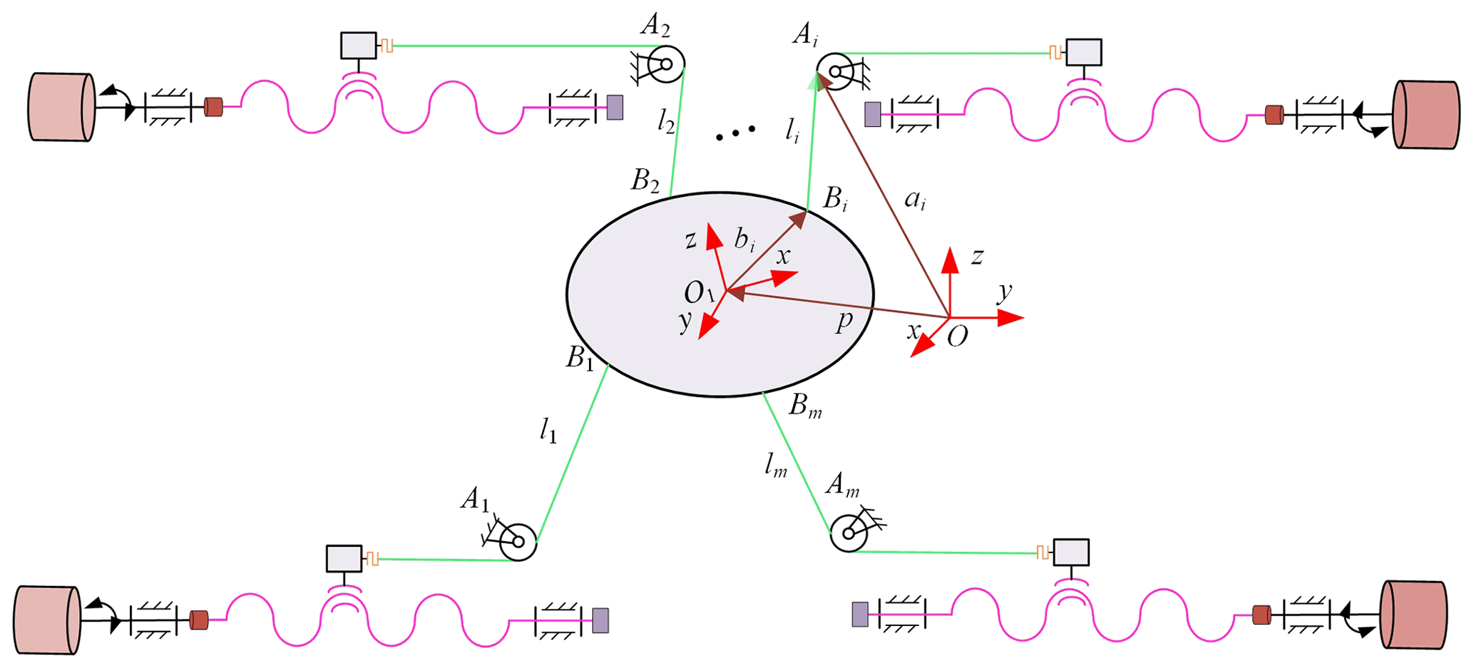
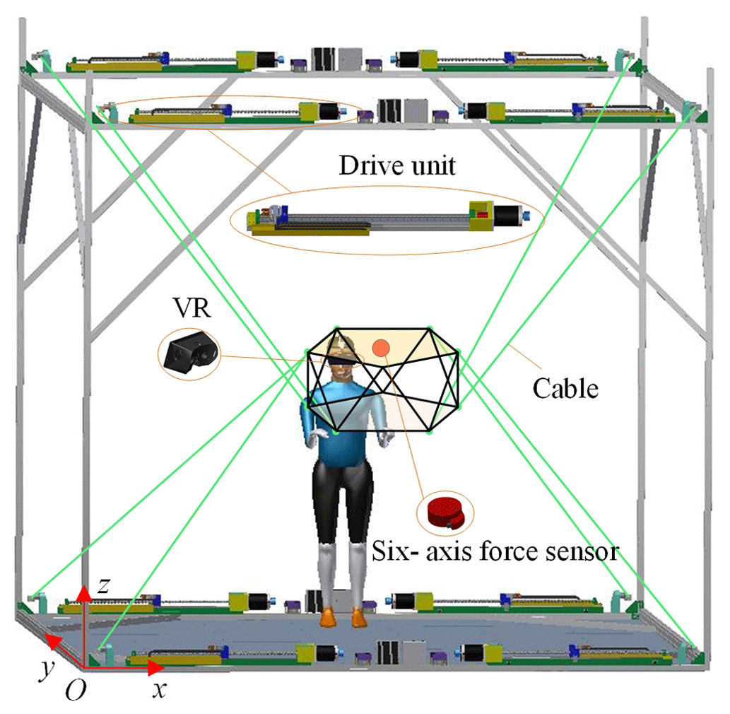
The HIR based on a cable-driven parallel mechanism is composed of a fixed platform, a ball screw drive unit, an end effector, and a transmission device. The ball screw drives one end of the cable to move in a straight line, and the other end is connected to the end actuator. The cable transfers movement and force to the end actuator to realize its free, stable, and flexible movement in multiple spaces.
2.1 General robot configuration
The general robot model is shown in Fig. 1. Assume that the global coordinate system is (O, x, y, z); the local coordinate system is (O1, x, y, z); Ai is the output point of the cable on the fixed platform; Bi is the connection point between the cable and end actuator; li is the length of the cable; ai is the vector of the cable output point on the fixed platform in the global coordinate system; bi is the vector from the end actuator center to the cable connection point; p is the vector in the local coordinate system, O1, at the end actuator center in the global coordinate system, O; and the attitude angle is given by (α, β, γ).
2.2 Optimization of configuration topology
Since trainers must stand inside the fixed platform for operation training, the arms must be able to move conveniently in the space without interference from the cables. This improves the mobility of the end effector, reduces the interference between the cables and the end effector, and decreases the difficulty in implementing control.
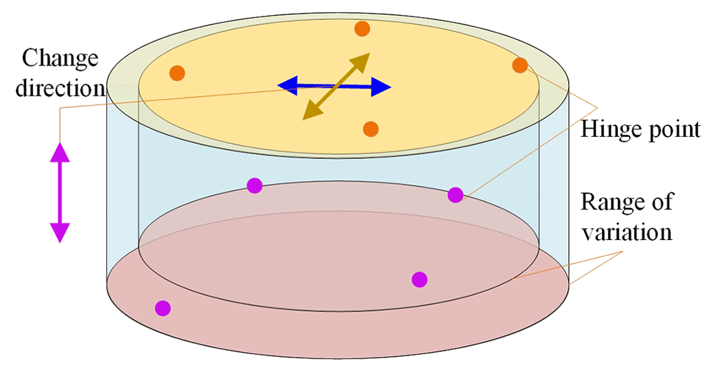
The dimension synthesis optimization strategy reported in Hamida et al. (2021) is used to optimize the configuration of the end effector. The size of the mechanism is determined according to the working requirements of the HIR. To maximize the spatial rotation angle of the end effector and minimize the interference among cables, the objective function and constraints are set as follows:
where ϖ(G) is the spatial rotation angle of the end actuator, Hk(G) is the distance between the cable and boundary of the end actuator, is the change in the value of the hinge point of the end actuator, and (, ) is the variable search range.
The side length of the square fixed platform is set considering the operation and sensor installation size requirement, Γ = 4000 mm. As shown in Fig. 2, the initial shape of the end actuator is a cylinder (radius (r) = 300 mm; height (h) = 200 mm). The optimization is implemented according to the scale synthesis optimization algorithm. The hinge point varies along the direction indicated by the arrow in Fig. 2.
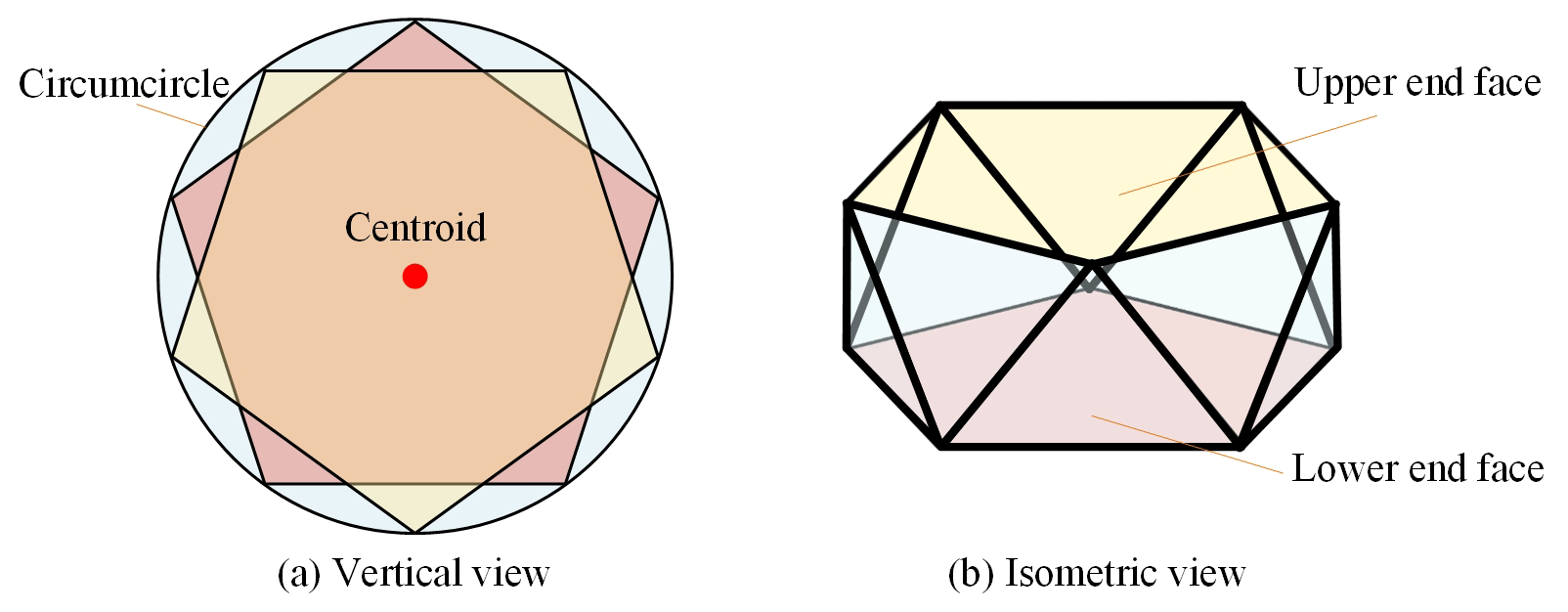
By approximating the configuration and rounding the side length, the configuration of the end effector is obtained, as shown in Fig. 3. The upper and lower end faces are regular pentagons with a side length, Ω, of 500 mm. The top view in Fig. 3a shows that centroids coincide. The 3D configuration is shown in Fig. 3b.
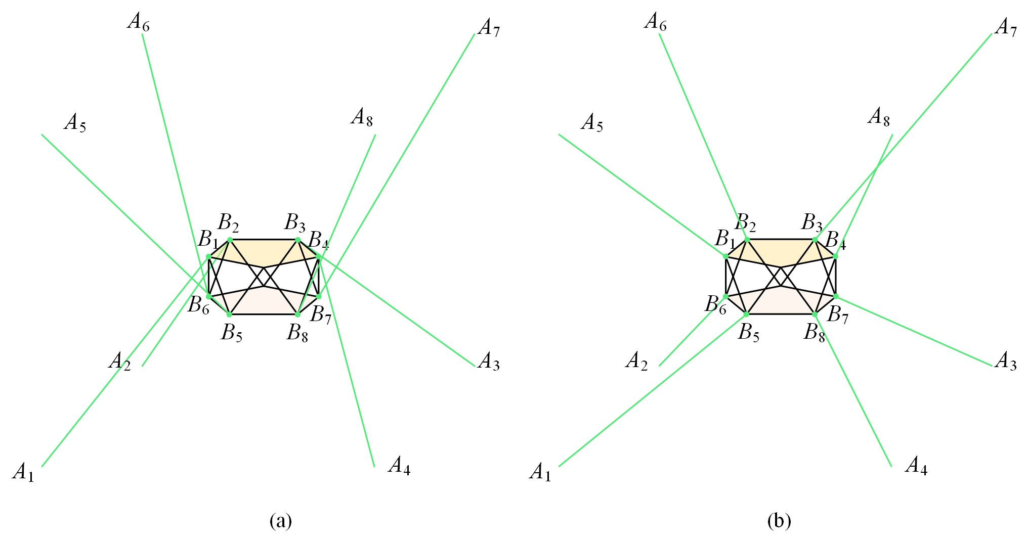
Based on the optimized configuration of the end effector, two cable layout schemes are shown in Fig. 4. To allow the end effector to rotate more freely, the scheme shown in Fig. 4a is selected as the final configuration scheme for the HIR.
Table 1Local positions of eight anchor points (unit: millimeters).
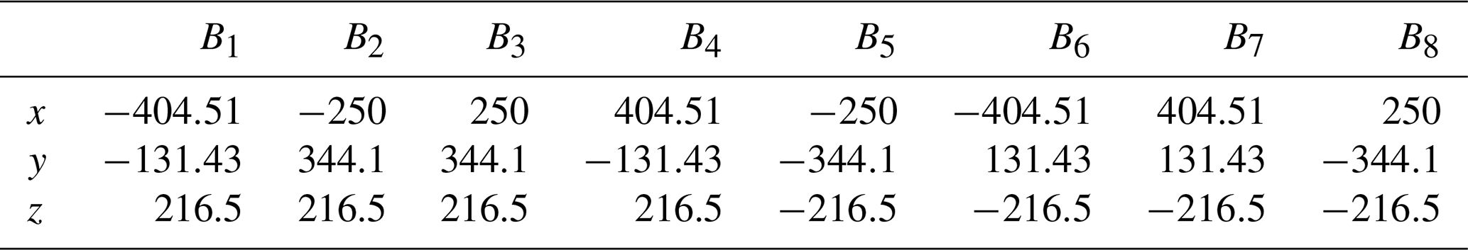
The positions of the hinge point between the cable and end actuator of the force feedback robot are summarized in Table 1.
The HIR requires high control accuracy. It must solve the forward and inverse kinematics of the robot and cable tension. The robot kinematics are inverse and forward. Inverse kinematics determines the length of the cable by determining the position and attitude of the center of mass of the end effector. Forward kinematics solves the position and attitude of the center of mass of the robot end effector with the known cable length.
3.1 Inverse kinematics model
The movement of the cable is driven by the ball screw; hence, the cable is not wound around the drum. Moreover, the mass and elasticity of the cable slightly change; thus, the influence of these two factors is not considered. The robot configuration is shown in Fig. 5. The length of the cable is measured by the encoder on the drive unit, and the interaction force exerted by the human body on the end effector is detected by the six-axis force sensor.
The coordinate system, O–xyz, is established at point A1, and O1–xyz is established at the center of the mass of the end actuator; this centroid is at position χ0. According to the layout of this new configuration scheme, the inverse kinematics model of the robot is established as
The derivative of Eq. (2) with respect to time is
where , and ω is the angular velocity of the end actuator around the coordinate axis.
Because ai and bi are constants in the global and local coordinate systems, further rearrangement yields
Multiply Eq. (6) by and simplify
The Jacobi matrix, AT, and end actuator speed, , are as follows:
The cable speed changes to
The change in cable acceleration is
3.2 Forward kinematics model
The forward kinematics of HIR based on a cable-driven parallel mechanism calculates the location and pose of the end effector corresponding to a given cable length; the Newton–Raphson iterative algorithm is typically used (Pott and Schmidt, 2015; Lau et al., 2016). Set the initial value, solve the nonlinear equation by iteration, and halt the iteration when the solution encounters an error.
According to Eq. (1), the objective function is constructed as
According to the Newton–Raphson iterative algorithm,
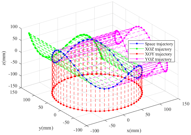
The aforementioned algorithm locally converges, and the selection of an appropriate initial value can ensure convergence. To verify the correctness of the forward and inverse kinematics model, a joint simulation of the forward and inverse kinematics is implemented. Moreover, set the motion track of the end actuator center of mass point, χ0, in 3D space as
The space trajectory of Eq. (15) is shown in Fig. 6. The trajectory motion is relatively complex, ensuring that the robot can complete complex tasks.
Calculate the length of each cable according to Eq. (2), substitute the
cable length value into Eq. (12), and calculate the motion track of
the end actuator center of mass according to Eq. (12). The forward and
inverse kinematics joint simulation algorithm is described as follows.
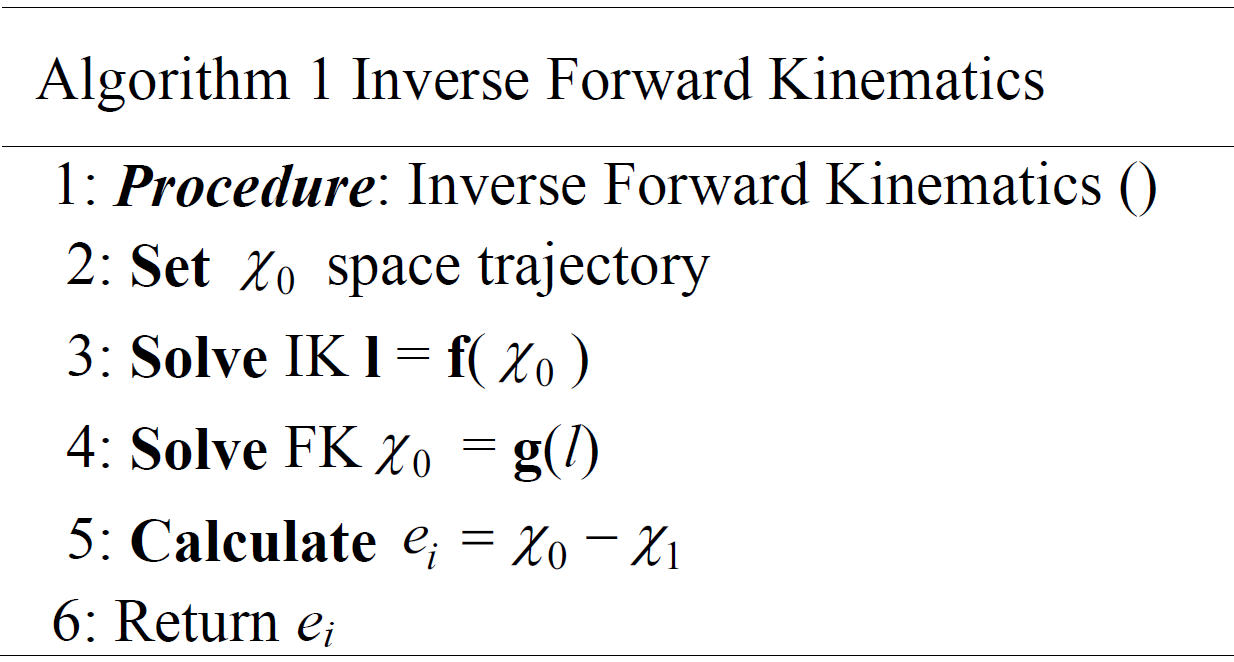
Through this joint simulation algorithm, the expected and actual trajectories of different planes are obtained, as shown in Fig. 7a–c; the trajectory error is shown in Fig. 7d.
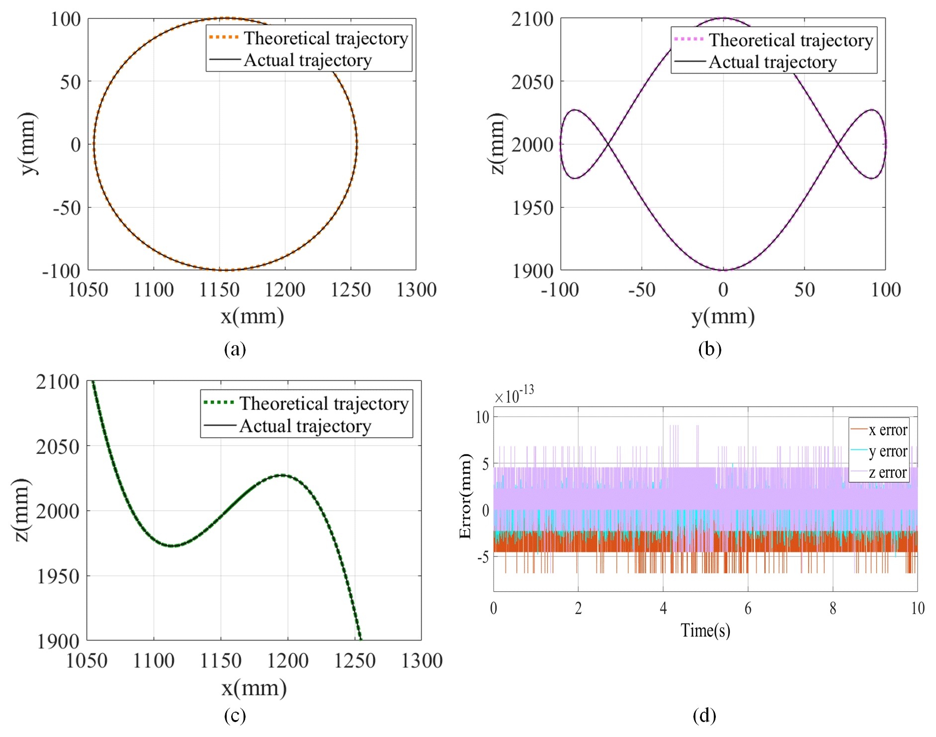
As shown in Fig. 7a–c, the expected trajectory projected on each plane virtually coincides with the actual trajectory. The order of magnitude of the trajectory error is 10−13, as shown in Fig. 7d. This proves that the expected trajectory is fundamentally consistent with the actual trajectory. This proves the correctness of the forward and inverse kinematics model of the HIR formulated in this study.
The force of the HIR is complex, and the cable tension distribution to obtain the difference in cable tension is critical to the stability of the robot.
4.1 Dynamic model
The sampling Lagrangian modeling method for the dynamic model of HIR (Shang et al., 2020; Babaghasabha et al., 2014; Khosravi and Taghirad, 2014) yields the kinetic energy, ED, of the end actuator as
where me is the mass of the end actuator; is the identity matrix; v∈R3 and w∈R3 are the translation and angular rotation speeds of the end effector, respectively; and represents the inertia matrix of the end effector in the local coordinate system.
Similarly, the potential energy, S, of the end actuator is
where g is the gravitation acceleration, and x is the displacement of the end actuator center of mass in the direction of gravity.
The combination of Eqs. (16) and (17) yields the Lagrange equation of the end actuator as
where is a Jacobian matrix; F∈Rm is the cable tension matrix; and W∈Rn represents the external force, Fh, and moment, Mh.
Substitute Eq. (18) into Eq. (19),
where M(X) is the inertia matrix, is the centrifugal and Coriolis force matrices, and G is the gravity vector.
Set a group of determined dynamic parameters. Re-express Eq. (20) as (An et al., 1985; Khosla and Kanade, 1985)
where N∈Rn represents the resultant force and moment of the end actuator.
4.2 Tension distribution
Based on the dynamic model, the tension in each cable is
According to the cable characteristics, the solution of Eq. (22) is (Ouyang and Shang, 2016)
In Eq. (23), is the special solution, Fg=Null(A)λ is the general solution, is the Moore–Penrose inverse of A, is the null space vector of A, and is an arbitrary vector.
Set the tension condition of the cable according to the physical characteristics of the drive unit and cable, as follows:
In Eq. (14), Fmax and Fmin are the maximum and minimum tension values in the cable, respectively.
To generate a smooth initial cable tension change and stabilize the system, reduce the system vibrations due to sudden changes in cable tension. The change in cable tension must also satisfy the following condition:
where Fimax and Fjmin are the maximum and minimum tension values of the eight cables. The smaller the ratio, the more gradual the change in tension.
Considering the real-time requirements of the HIR, a quadratic programming (QP) solution is implemented to minimize the tension, λ. The optimization algorithm is
The optimization process in the foregoing algorithm is simple. The feasible solution consists of two-dimensional convex sets of λ with extreme values (Shang et al., 2020). The tension distribution process is shown in Fig. 8.

The space trajectory of the HIR is within the feasible workspace of the force screw. The mass of the end effector is 18.62 kg. The minimum and maximum tensile forces in the cable are 30 and 1000 N, respectively. The position of the hinge point of the end actuator relative to the local coordinate system is listed in Table 1. The tension distribution and change cable in length are shown in Fig. 9a and b, respectively.
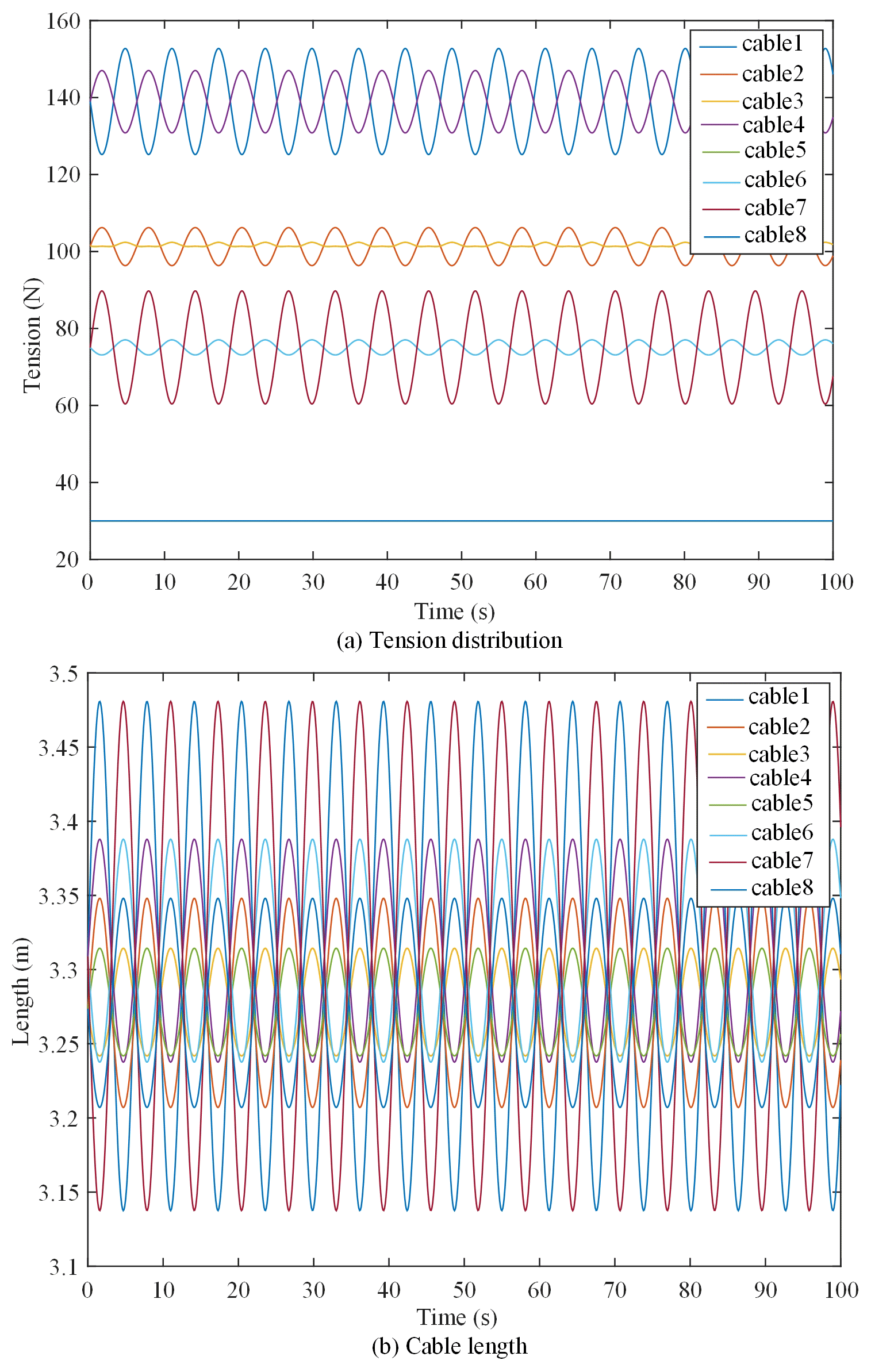
As shown in Fig. 9, the cable tension is between the minimum and maximum values, and the ratio of the maximum to the minimum tensile forces in the eight cables is greater than 1 but less than 6. The change in the cable length is continuous. The foregoing proves that the tensile force yielded by the proposed tension distribution algorithm is considerably stable. Moreover, the change in cable length is stable and continuous.
A double closed-loop scheme is adopted for the design of the driver controller. The inner loop speed suppresses interference, and the outer loop position protection ensures driver position accuracy. The design requires that the speed loop bandwidth is not less than 5 times the bandwidth of the position loop. When the controller is designed with a known transfer function, a stable and reliable classical control theory is adopted. The HIR adopts the same drive unit servo motor, ball screw module, cable, and drive chain structure; thus, only one of the drive unit controllers is designed.
5.1 Mathematical model of drive unit
The drive unit is a direct curve (DC) electric servo system. The rotor of the DC motor generates the driving torque under the action of the armature current. Then, the motor transfers the torque to the cable through the ball screw mechanism. The cable drives the load movement. The drive unit can be simplified as the model shown in Fig. 10 (ua is the armature voltage, La is the armature inductance, Ra is the armature circuit resistance, Cm is the torque constant, e is the back electromotive force (EMF), and Ce is the back EMF constant). The drive unit model is mainly composed of the electric circuit model of the motor and the force balance equation of the ball screw.

The electric circuit equation of the motor is
The equation of the back EMF is
The moment equation is
where Tm is the driving torque, and ia is the armature current.
The force balance equation is
where Jm is the comprehensive converted moment of inertia of the motor rotor and load; Bm is the comprehensive converted damping of the motor rotor and load; Ks is the transmission ratio of the motor rotor to the sliding block translation; and F1 is the cable tension.
Equations (28) and (29) are obtained by simultaneous Laplace transformation. The following equation is also transformed:
After the Laplace transformation of Eqs. (29), (30), and (31), the mathematical model of the drive unit is obtained as follows:
where M1(s) and M2(s) are
The model block diagram of the drive unit obtained from Eqs. (31) and (32) is shown in Fig. 11.
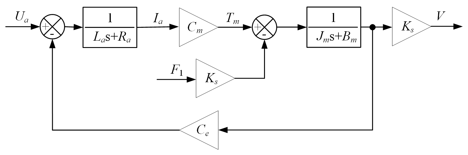
As shown in Fig. 11, the output speed of the drive unit is determined by the armature voltage and slider load torque. When the load force is fixed, the slider speed can be controlled by changing the armature voltage of the motor. When the armature voltage of the motor is fixed, the change in the load force can cause the motor speed to change. Therefore, to eliminate the fluctuation of the slider speed caused by the change in the load torque, the slider speed must be accurately controlled through the closed-loop control of the motor speed feedback.
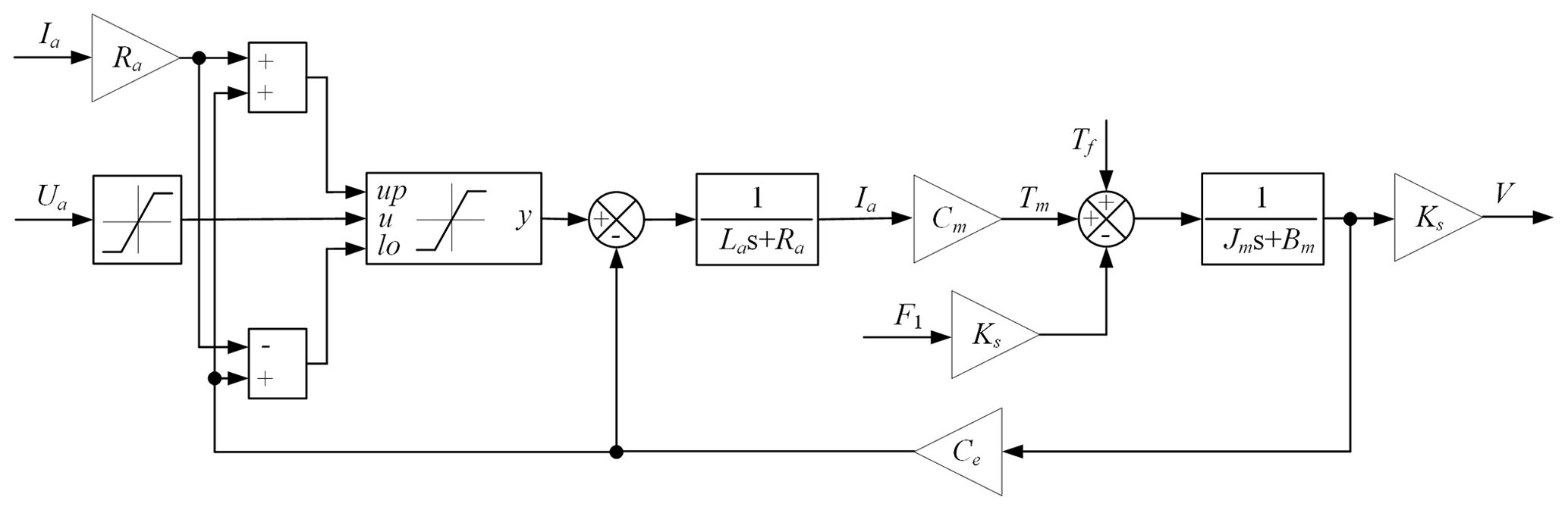
The controlled drive unit must also include the mechanical and control parts. By ignoring the influence of drive unit stiffness and considering the electric circuit equation (Eq. 27) of the motor, the drive unit model improves, as shown in Fig. 12. The drive unit limits current by limiting voltage. Resolving the problem of limiting the current in the control strategy also protects the drive unit because the voltage and current of the unit are regulated at the same time. Conventional hardware current chopping, current inner loop, and other methods typically allow current overload and adopt shutdown to protect equipment. The proposed drive unit model avoids the foregoing situations and protects equipment without halting equipment operation.
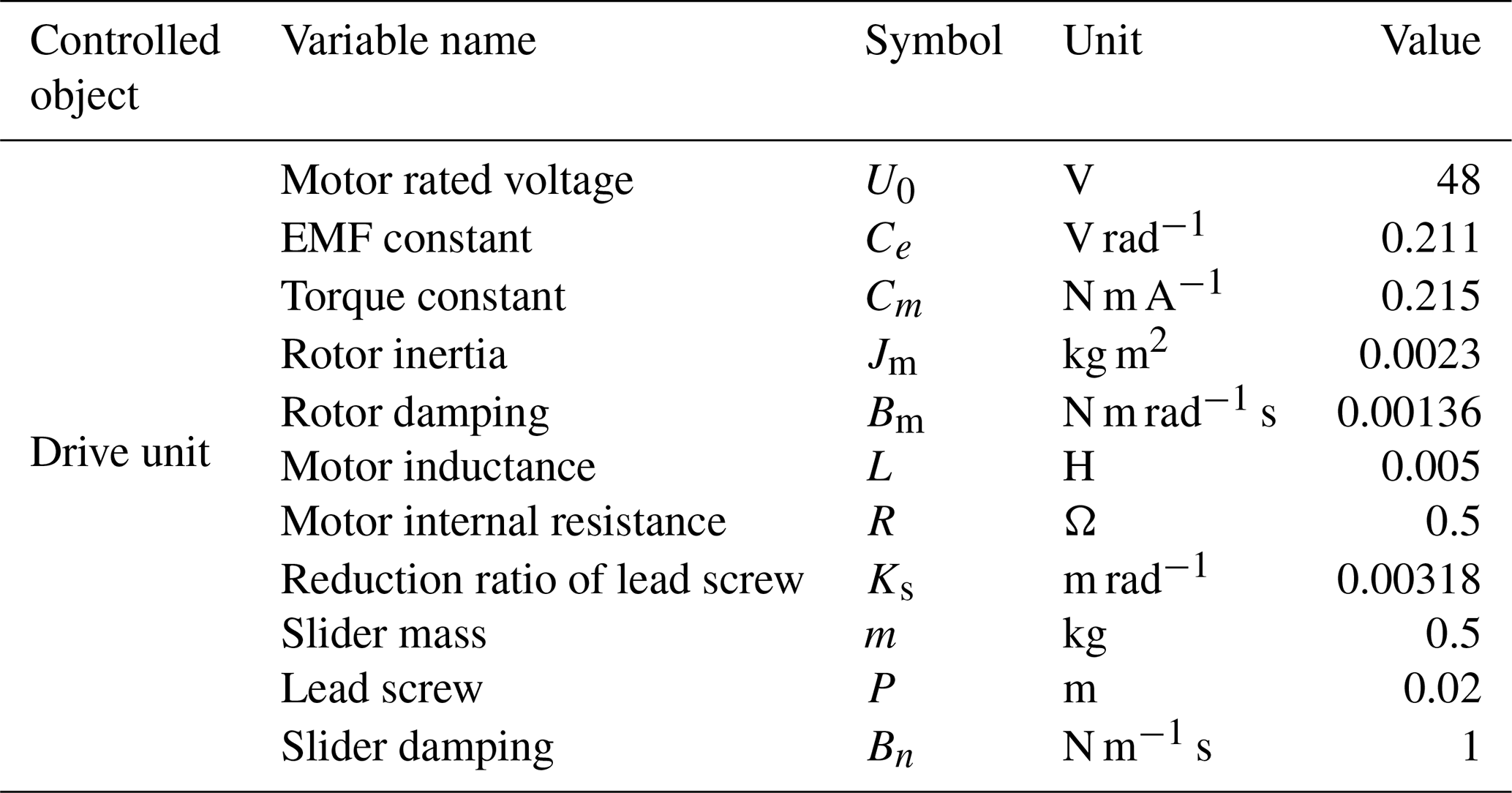
The drive unit parameters are summarized in Table 2. Equipment parameters are provided by component manufacturers and measured by experiments. All controller design and simulation experiments adopt the listed parameters.
5.2 Controller design
5.2.1 Speed controller
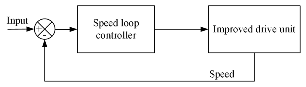
The motor speed is fed back by the drive unit encoder. The control block diagram of the closed-loop system of the motor speed is shown in Fig. 13.
Without considering the change in the cable tension of the drive unit, the driving function of the drive unit is expressed as
Substitute the drive unit parameters listed in Table 2 into Eq. (35). This derives the transfer function of the drive unit:
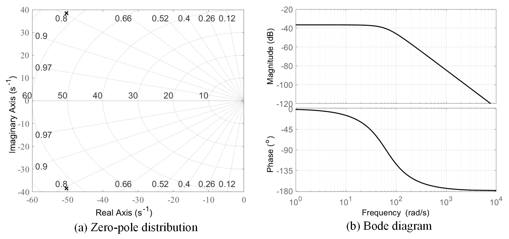
According to Eq. (36), the two poles of the transfer function are and . The poles are on the left-half plane of the S domain, and the system is in the minimum phase. The system's natural frequency, damping ratio, and open-loop gain are wn=63.2772 rad s−1, ξn=0.7949, and K=59.51, respectively, as shown in Fig. 14a. When the drive unit is within the operating frequency range, the amplitude–frequency characteristic of the system's forward channel transfer function is stable. Moreover, the phase frequency characteristic is approximately linearly transformed, and the correction system forward channel is relatively simple, as shown in Fig. 14b.
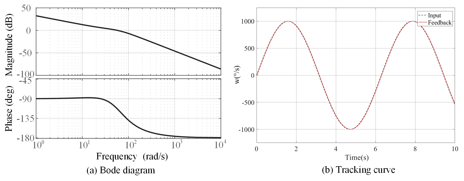
Figure 15Open-loop Bode diagram and sine tracking curve of system after speed loop correction.
Because the forward channel of the drive unit is a type-0 system, the loading of the high-order static error-free system cannot be satisfied, and the hysteretic characteristics lead to the inadequate dynamic performance of the system. The proportional–integral–derivative (PID) controller is used to correct the forward channel, improve the steady-state accuracy of the drive unit, and eliminate the steady-state error. The transfer function, Gc2, of the PID controller is
The designed controller parameters are kpi=0.0047 and kvi=33.5319. The system's open-loop Bode diagram after calibrating the speed loop controller is shown in Fig. 15a. The shear frequency and phase margin are wc=57.6 rad s−1 and 66.6∘, respectively. The amplitude–frequency characteristic crosses the 0 dB line with a slope of −20 dB per decade. After correcting the speed loop, the system stability and rapidity are ensured, and the steady-state error of the system is eliminated. The situation of the system when the sine signal with an amplitude of 1000 is inputted is shown in Fig. 15b. The system is stable with a maximum error of 5∘. The system phase lag time is 0.0081 s.
5.2.2 Double closed-loop controller
The block diagram of the position and speed double closed-loop control system is shown in Fig. 16.
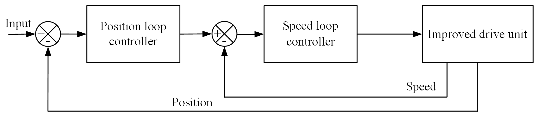
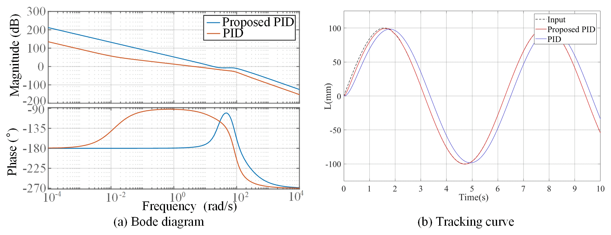
Figure 17Proposed controller compared with traditional PID Bode diagram and sinusoidal tracking curve.
When the PID controller is started or the amplitude of the input signal significantly varies, the system output deviates considerably. Moreover, the integral of the controller operation accumulates, thus overshooting the system and oscillation. To stabilize the system and improve its dynamic tracking control accuracy, the position loop adopts a variable speed integral separation PID controller. This PID controller can adjust integration and modify integration speed according to the deviation of the system. A pure differential link of the actual system is physically impossible, and high-frequency noise easily infiltrates. Given this, the differential link is connected in series using a low-pass filter with a cutoff frequency of N rad s−1. Coefficient f(e), which is related to deviation change, is introduced to modify the integral strength. The variable speed integral separation PID transfer function is
Set the relationship between deviation e and f(e) as
For this system, ε1=0.2 mm, ε2=0.8 mm, kpj = 72 000, kvj=100, kdj=0.12, and N=200 are selected for simulation debugging. When the influence of nonlinear factors is ignored, the open-loop Bode diagram of the system after correcting the proposed position and PID controllers is shown in Fig. 17a. The turning frequency of the proposed position controller exceeds that of the PID controller and is considerably stable. The input is the typical sine signal, S=100sin (t). The resulting situation of the system is shown in Fig. 17b. The performance of the proposed control system is better than that of the PID controller, and the system's dynamic performance is satisfactory. When t=1.71 s, system integration is complete.
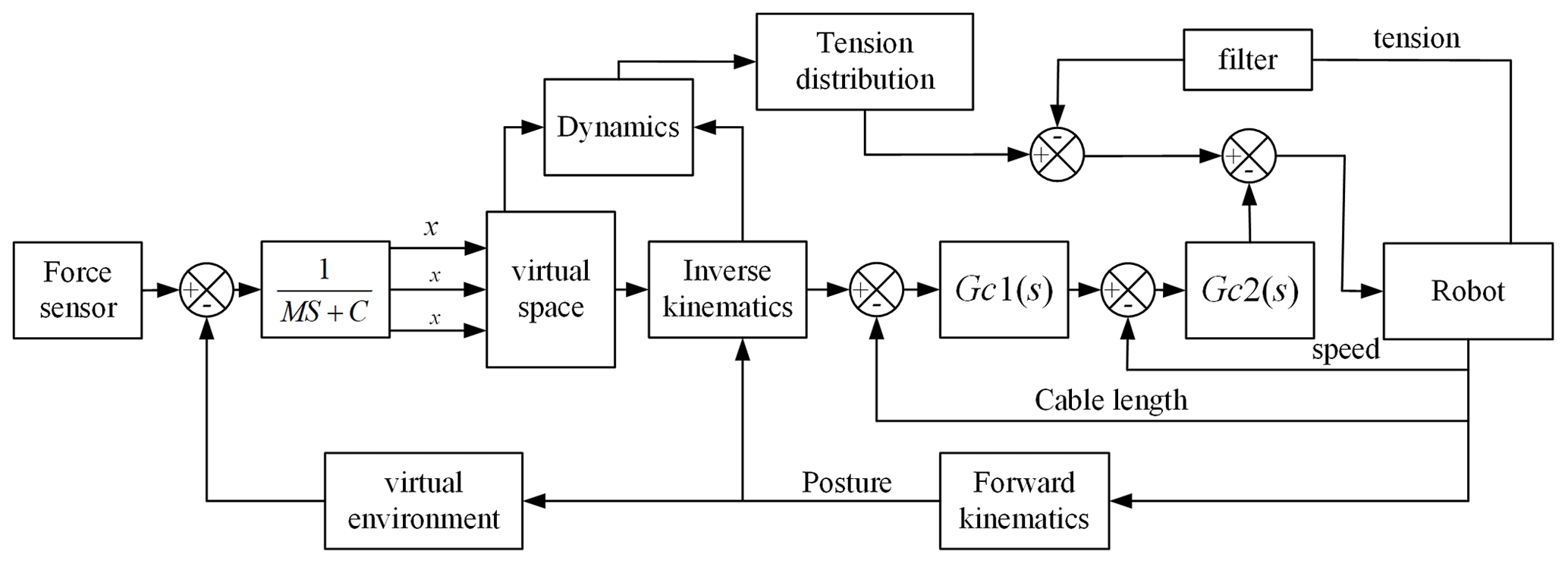
5.3 Control strategy of robot system
The control strategy of the HIR system is shown in Fig. 18.
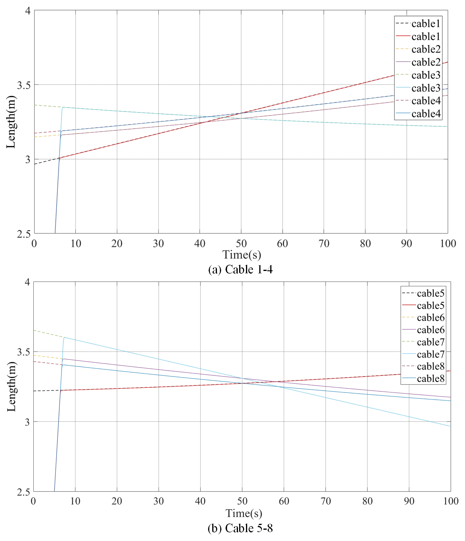
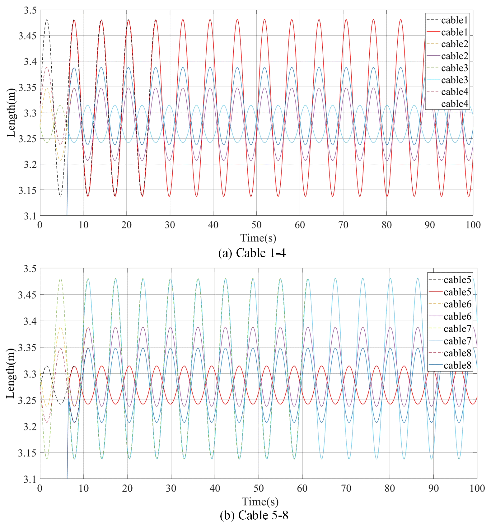
To verify the correctness of the proposed control strategy for the HIR system, the strategy is used to complete the space trajectory of Eq. (15). The combination of the force exerted by the operator and the force generated by the virtual environment is given by . The results are shown in Fig. 19.
The dotted line in Fig. 19 represents the theoretical value of the corresponding cable, generated by the admittance model, and the solid line represents the drive unit following the theoretical value. In 6 s, the drive unit fully enters the following state with satisfactory tracking performance; tracking is stable for 100 s.
To demonstrate the stability of the system control strategy further, a 10 N force is applied to the end actuator, causing it to move along a straight line; the simulation results are shown in Fig. 20. The dotted line is the theoretical value of the corresponding cable generated by the admittance model, and the solid line is the theoretical value of the following drive unit. In 5 s, the drive unit completely enters the following state with satisfactory tracking performance; tracking is stable for 100 s. Therefore, the proposed drive unit and robot system control strategies can stabilize the system.
In this study, a new drive unit configuration and an end effector configuration are proposed for HIRs. The drive unit configuration can improve the motion accuracy of the cable, and the end effector configuration can render the cable motion flexible. The algorithm for distributing cable tension is improved to render the change in cable tension gradual. The mathematical model, control strategy, over-current protection, and motion control accuracy of the drive unit are enhanced. Moreover, a control strategy for stabilizing the control of the HIR system is proposed.
In future studies, the HIR will be optimized, considering human–robot interaction safety and other conditions to reduce volume and build a compact robot. The control strategy of the robot system will be improved, such that the drive unit can rapidly and accurately follow the theoretical trajectory.
All the data used in this paper can be obtained by request from the corresponding author.
DS and XX finished optimization of configuration topology, kinematics model, and tension distribution. DS, GL, LZ, and FX finished the design of the control strategy. LL participated in correction of the paper.
The contact author has declared that none of the authors has any competing interests.
Publisher’s note: Copernicus Publications remains neutral with regard to jurisdictional claims in published maps and institutional affiliations.
The author thanks the editors and reviewers for their efforts.
This research has been supported by the National Natural Science Foundation of China (grant no. 61773007), Scientific Research Project of Jilin Province Department of Education (grant no. JJKH20210108KJ), and Northeast Electric Power University Doctoral Research Launch Fund (grant no. BSJXM-2020223).
This paper was edited by Zi Bin and reviewed by three anonymous referees.
Aflakian, A., Safaryazdi, A., Tale Masouleh, M., and Kalhor, A.: Experimental study on the kinematic control of a cable suspended parallel robot for object tracking purpose, Mechatronics, 50, 160–176, https://doi.org/10.1016/j.mechatronics.2018.02.005, 2019.
Amare, Z., Zi, B., Qian, S., and Zu, L.: Dynamic analysis of electrohydraulic cable-driven parallel robots, P. I. Mech. Eng. C-J. Mec., 233, 1989–1996, https://doi.org/10.1177/0954406218815715, 2019.
An, C. H., Atkeson, C. G., and Hollerbach, J. M.: Estimation of inertial parameters of rigid body links of manipulators, in: 24th IEEE Conference on Decision and Control, 11–13 December 1985, Fort Lauderdale, FL, USA, 990–995, https://doi.org/10.1109/cdc.1985.268648, 1985.
Babaghasabha, R., Khosravi, M., and Taghirad, H.: Adaptive robust control of fully-constrained cable driven parallel robots, Mechatronics, 25, 27–36, https://doi.org/10.1016/j.mechatronics.2014.11.005, 2014.
Chawla, I., Pathak, P. M., and Notashb, L.: Inverse and forward kineto-static solution of a large-scale cable-driven parallel robot using neural networks, Mech. Mach. Theory, 179, 105107, 10.1016/j.mechmachtheory.2022.105, 2023.
Chen, Q., Zi, B., Sun, Z., Li, Y, and Xu, Q.: Design and development of a new cable-driven parallel robot for waist rehabilitation, IEEE-ASME T. Mech., 24, 1497–1507, https://doi.org/10.1109/tmech.2019.2917294, 2019.
Cho, Y., Cheong, J., Kim, M. G., Yi, B. J., and Kim, W.: Efficient optimal force distribution method of the parallel mechanism with actuator redundancy based on geometric interpretation, J. Mech. Sci. Technol., 33, 2915–2928, https://doi.org/10.1007/s12206-019-0539-z, 2019.
Cui, Z., Tang, X., Hou, S., and Sun, H.: Non-iterative geometric method for cable-tension optimization of cable-driven parallel robots with 2 redundant cables, Mechatronics, 59, 49–60, https://doi.org/10.1016/j.mechatronics.2019.03.002, 2019.
Duan, Q., Vashista, V., and Agrawal, S. K.: Effect on wrench-feasible workspace of cable-driven parallel robots by adding springs, Mech. Mach. Theory, 86, 201–210, https://doi.org/10.1016/j.mechmachtheory.2014.12.009, 2015.
Duan, X., Qiu, Y., Mi, J., and Zhao, Z.: Motion prediction and supervisory control of the macro–micro parallel manipulator system, Robotica, 29, 1005–1015, https://doi.org/10.1017/s0263574711000282, 2011.
Fang, S., Franitza, D., Torlo, M., Bekes, F., and Hiller, M.: Motion control of a tendon-based parallel manipulator using optimal tension distribution, IEEE-ASME T. Mech., 9, 561–568, https://doi.org/10.1109/TMECH.2004.835336, 2004.
Fortin-Côté, A., Cardou, P., and Gosselin, C.: An admittance control scheme for haptic interfaces based on cable-driven parallel mechanisms, in: IEEE International Conference on Robotics and Automation (ICRA), 31 May–7 June 2014, Hong Kong, China, 819–825, https://doi.org/10.1109/icra.2014.6906949, 2014.
Ghrairi, K., Chaker, A., Salah, S., and Bennour, S.: Development of a cable-driven parallel robots for functional rehabilitation, design and modeling of mechanical systems, Springer, Cham, 554–563, https://doi.org/10.1007/978-3-031-14615-2_62, 2023.
Gosselin, C.: Cable-driven parallel mechanisms: state of the art and perspectives, Mechanical Engineering Reviews, 1, 1–17, https://doi.org/10.1299/mer.2014dsm0004, 2014.
Gouttefarde, M., Lamaury, J., Reichert, C., and Bruckmann, T.: A versatile tension distribution algorithm for n-DOF parallel robots driven by n+2 cables, IEEE T. Robot., 31, 1444–1457, https://doi.org/10.1109/TRO.2015.2495005, 2015.
Hamida, I. B., Laribi, M. A., Mlika, A., Romdhane, L., and Carbone, G.: Multi-objective optimal design of a cable driven parallel robot for rehabilitation tasks, Mech. Mach. Theory, 156, 104141, https://doi.org/10.1016/j.mechmachtheory.2020.104141, 2021.
Hao, J., Shang, W., and Cong, S.: Adaptive synchronization control of cable-driven parallel robots with uncertain kinematics and dynamics, IEEE T. Ind. Electron., 68, 8444–8454, https://doi.org/10.1109/TIE.2020.3013776, 2021.
Hussein, H., Santos, J. C., Izard, J. B., and Gouttefarde, M.: Smallest maximum cable tension determination for cable-driven parallel robots, IEEE T. Robot., 37, 1186–1205, https://doi.org/10.1109/TRO.2020.3043684, 2021.
Jamshidifar, H., Khajepour, A., Fidan, B., and Rushton, M.: Kinematically-constrained redundant cable-driven parallel robots: modeling, redundancy analysis, and stiffness optimization, IEEE-ASME T. Mech., 22, 921–930, https://doi.org/10.1109/tmech.2016.2639053, 2017.
João, C. S., Marc, G., and Ahmed, C.: A nonlinear model predictive control for the position tracking of cable-driven parallel robots, IEEE T. Robot., 38, 2597–2616, https://doi.org/10.1109/TRO.2022.3152705, 2022.
Khosla, P. and Kanade, T.: Parameter identification of robot dynamics, in: 24th IEEE Conference on Decision and Control, 11–13 December 1985, Fort Lauderdale, FL, USA, 1754–1760, https://doi.org/10.1109/cdc.1985.268838, 1985.
Khosravi, M. and Taghirad, H.: Robust PID control of fully-constrained cable driven parallel robots, Mechatronics, 24, 87–97, https://doi.org/10.1016/j.mechatronics.2013.12.001, 2014.
Korayem, M. H., Yousefzadeh, M., and Tourajizadeh, H.: Optimal control of a wheeled mobile cable-driven parallel robot ICaSbot with viscoelastic cables, Robotica, 38, 1513–1537, https://doi.org/10.1017/S0263574719001607, 2020.
Lau, D., Eden, J., Ying, T., and Oetomo, D.: CASPR: A comprehensive cable-robot analysis and simulation platform for the research of cable-driven parallel robots, in: IEEE/RSJ International Conference on Intelligent Robots and Systems (IROS), 9–14 October 2016, Daejeon, South Korea, 3004–3011, https://doi.org/10.1109/iros.2016.7759465, 2016.
Lu, B., Fang, Y., Sun, N., and Wang, X.: Antiswing control of offshore boom cranes with ship roll disturbances, IEEE T. Contr. Syst. T., 26, 740–747, https://doi.org/10.1109/TCST.2017.2679060, 2017.
Meziane, R., Cardou, P., and Otis, J. D.: Cable interference control in physical interaction for cable-driven parallel mechanisms, Mech. Mach. Theory, 132, 30–47, https://doi.org/10.1016/j.mechmachtheory.2018.10.002, 2018.
Nguyen, V. and Caverly, R. J.: Cable-driven parallel robot pose estimation using extended kalman filtering with inertial payload measurements, IEEE Robotics and Automation Letters, 6, 3615–3622, https://doi.org/10.1109/LRA.2021.3064502, 2021.
Ouyang, B. and Shang, W.: Rapid optimization of tension distribution for cable-driven parallel manipulators with redundant cables, Chin. J. Mech. Eng., 29, 231–238, https://doi.org/10.3901/CJME.2015.1120.137, 2016.
Pannequin, R., Jouaiti, M., Boutayeb, M., Lucas, P., and Martinez, D.: Automatic tracking of free-flying insects using a cable-driven robot, Science Robotics, 43, 1–8, https://doi.org/10.1126/scirobotics.abb2890, 2020.
Picard, E., Plestan, F., Tahoumi, E., Claveau, F., and Caro, S.: Control strategies for a cable-driven parallel robot with varying payload information, Mechatronics, 79, 102648, https://doi.org/10.1016/j.mechatronics.2021.102648, 2021.
Pott, A. and Schmidt, V.: On the forward kinematics of cable-driven parallel robots, in: IEEE/RSJ International Conference on Intelligent Robots & Systems (IROS), 28 September—2 October 2015, Hamburg, Germany, 3182–3187, https://doi.org/10.1109/iros.2015.7353818, 2015.
Qian, S., Bao, K., Zi, B., and Zhu, W. D.: Dynamic trajectory planning for a three degrees-of-freedom cable-driven parallel robot using quintic b-splines, J. Mech. Design, 142, 1–13, https://doi.org/10.1115/1.4045723, 2020.
Rijk, R. D., Rushton, M., and Khajepour, A.: Out-of-plane vibration control of a planar cable-driven parallel robot using a multi-axis reaction system, IEEE-ASME T. Mech., 23, 1684–1692, https://doi.org/10.1109/TMECH.2018.2847708, 2018.
Rushton, M., Jamshidifar, H., and Khajepour, A.: Multiaxis reaction system (MARS) for vibration control of planar cable-driven parallel robots, IEEE T. Robot., 35, 1039–1046, https://doi.org/10.1109/TRO.2019.2906475, 2019.
Ryan, J. C. and James, R. F.: Flexible cable-driven parallel manipulator control: maintaining positive cable tensions, IEEE T. Contr. Syst. T., 26, 1874–1883, https://doi.org/10.1109/TCST.2017.2728007, 2017.
Shang, W., Zhang, B., Cong, S., and Lou, Y.: Dual-space adaptive synchronization control of redundantly-actuated cable-driven parallel robots, Mech. Mach. Theory, 152, 103954, https://doi.org/10.1016/j.mechmachtheory.2020.103954, 2020.
Sun, G., Liu, Z., Gao, H., Li, N., and Deng, Z.: Direct method for tension feasible region calculation in multi-redundant cable-driven parallel robots using computational geometry, Mech. Mach. Theory, 158, 104225, https://doi.org/10.1016/j.mechmachtheory.2020.104225, 2021.
Yao, R.,Tang, X.,Wang, J., and Huang, P.: Dimensional optimization design of the four-cable-driven parallel manipulator in fast, IEEE-ASME T. Mech., 15, 932–941, https://doi.org/10.1109/TMECH.2009.2035922, 2010.
Zake, Z., Chaumette, F., Pedemonte, N., and Caro, S.: Vision-based control and stability analysis of a cable-driven parallel robot, IEEE Robotics and Automation Letters, 4, 1029–1036, https://doi.org/10.1109/lra.2019.2893611, 2019.
Zarafshan, P., Mousavi, M. R., Ghanbari, M., and Moosavian, S.: Rapid and safe wire tension distribution scheme for redundant cable-driven parallel manipulators, Robotica, 40, 2395–2408, https://doi.org/10.1017/S0263574721001703, 2022.
Zi, B., Wang, N., Qian, S., and Bao, K.: Design, stiffness analysis and experimental study of a cable-driven parallel 3d printer, Mech. Mach. Theory, 132, 207–222, https://doi.org/10.1016/j.mechmachtheory.2018.11.003, 2019.