the Creative Commons Attribution 4.0 License.
the Creative Commons Attribution 4.0 License.
 | 17 Nov 2022
Development of a force-field-based control strategy for an upper-limb rehabilitation robot
Jiasheng Pan
Leigang Zhang
Qing Sun
Robot-assisted rehabilitation has proven to be effective for improving the motor performance of patients with neuromuscular injuries. The effectiveness of robot-assisted training directly depends on the control strategy applied in the therapy training. This paper presents an end-effector upper-limb rehabilitation robot for the functional recovery training of disabled patients. A force-field-based rehabilitation control strategy is then developed to induce active patient participation during training tasks. The proposed control strategy divides the 3D space around the rehabilitation training path into a human-dominated area and a robot-dominated area. It encodes the space around the training path and endows the corresponding normal and tangential force; the tangential component assists with movement along the target path, and the normal component pushes the patient's hand towards the target path using a real-time adjustable controller. Compared with a common force-field controller, the human–robot interaction in this strategy is easy and can be quickly adjusted by changing the force field's range or the variation characteristics of two forces, and the intervention in two directions can change continuously and smoothly despite the patient's hand crossing the two areas. Visual guidance based on the Unity-3D environment is introduced to provide visual training instructions. Finally, the feasibility of the proposed control scheme is validated via training experiments using five healthy subjects.
- Article
(3872 KB) - Full-text XML
- BibTeX
- EndNote


The number of patients with upper-limb motor dysfunction caused, for example, by stroke and spinal cord injury has increased sharply year over year (Malcolm et al., 2009). About two-thirds of stroke patients survive; however, more than 80 % of them may suffer hemiparesis. These survivors require prolonged physical therapy to recover motor function for the activities of daily living (ADLs) (Cortese et al., 2015). Research on neurological rehabilitation suggests that repetitive motor activity has positive effects with respect to improving movement coordination and avoiding muscle atrophy, and the therapeutic effect is mainly determined by the intention, task-oriented quality and sustainability of rehabilitation training. Robotic systems have a natural advantage in rehabilitation over traditional rehabilitation treatments (Bertani et al., 2017). Robot-assisted therapy can deliver long-endurance, repetitive and sustainable therapeutic training using programmable control strategies (Milot et al., 2013). Furthermore, therapists can obtain a series of quantitative assessments of patient training performance to further optimize the treatment strategies (Mehrholz et al., 2012). In recent decades, the application of robotic systems to the rehabilitation treatment of neuromuscular impairment has received increasing attention from around the world (Krebs et al., 2004; Gassert and Dietz, 2018). To date, many rehabilitation robots have been developed, including end-effector and exoskeleton robots. With respect to the aforementioned robot systems, end-effector rehabilitation robots have attracted plenty of interest from widespread researchers, resulting in the development of systems such as MIT-MANUS (Hogan et al., 1992), GENTLE/S (Loureiro et al., 2003), REHAROB (Andras et al., 2009), ACRE (Schoone et al., 2007) and PASCAL (Keller et al., 2013).
The effectiveness of robot-assisted rehabilitation treatment is largely determined by the control strategy applied in the therapy training (Jiang et al., 2012; Kahn et al., 2004). Various kinds of control strategies have been developed for end-effector upper-limb rehabilitation robots in order to execute predetermined training tasks. The existing control methods can be classified into passive control strategies and cooperative control strategies according to the interaction between humans and rehabilitation robots (Lindberg et al., 2004). In the early stages of hemiplegia recovery, the patient's affected limb is completely paralyzed, without any muscle contraction or active movement. The passive control strategy is particularly applicable in this situation, as the robot assists the patient to passively perform repetitive flexion and extension training tasks along a predetermined path, helps the patient maintain the normal range of joint movement (Proietti et al., 2016), and lays the foundation for active training. Many controllers have been proposed to ensure the performance of passive training, including fixed-gain PD (proportional and differentiation) controllers (French et al., 2014), neural network-based PI (proportional and integral) controllers (Erol et al., 2005), fuzzy logic PD controllers (Xu et al., 2011), dynamic fuzzy network impedance controllers (Song et al., 2014) and so on. However, if the motion-related central nervous system has been restored but is still weak, a cooperative control strategy can be used, which emphasizes fully mobilizing the patient's intention to actively exercise during a training task in order to maximize the efficiency of rehabilitation training (Mounis et al., 2019). Therefore, the control strategy applied during this stage should facilitate patient–robot interaction with minimal robot intervention and maximal patient effort (Wu et al., 2018; Frisoli et al., 2009; Akiyama et al., 2015; Lee et al., 2020). Wang et al. (2019) developed an end-effector upper-limb rehabilitation robot based on fuzzy logic rules and impedance control; this system uses recursive least squares to estimate the human impedance parameters and quantify the residual motor capacity. These parameters and the motion deviations are input into the fuzzy logic controller. Zhang et al. (2020a) proposed an impedance-based assist-as-needed controller that enables the patient to move freely in the fault-tolerant region and provides assistance according to the patient's functional ability when deviating from the fault-tolerant region. A new performance-based assistance method was developed by Leconte and Ronsse (2016) that can assess the movement features of smoothness, velocity and amplitude during training tasks. Krebs et al. (2003) proposed a novel concept of performance-based progressive robot therapy that uses speed, time or electromyography (EMG) thresholds to initiate robot assistance. Cui et al. (2017) developed a wrench-based controller to conduct an exoskeleton with 7 degrees of freedom (7DOF) for dexterous motion training that contains four basic force/torque components which guide and correct the position/pose errors. Shi et al. (2022, 2020) proposed a human-centered control method for assist-as-needed (AAN) robotic rehabilitation, and they created a feedback-stabilized closest-attitude tracking algorithm according to the geometric properties of a special 3D orthogonal group, SO(3), and then realized the tracking of the robot to the desired position/posture by force/velocity field.
Therefore, the main purpose of this paper is to present a new patient-cooperative control framework for an end-effector upper-limb rehabilitation robot that provides robot-assisted training for individuals with neuromuscular disorders. First, a minimal-intervention force-field-based control strategy is proposed. It divides the 3D space around the rehabilitation training path into the patient-dominated area and the robot-dominated area, encodes the space, and provides the corresponding normal and tangential forces that guide the patient’s hand movement towards and along the target path, respectively; moreover, a damping term is added to maintain the stability of the system. The human–robot interaction can be adjusted by changing the force field's range or variation characteristics to meet the subjects' requirements during different recovery stages. The patient-dominated area enables greater patient initiative with less robot intervention; however, robot intervention increases significantly as the patient's hand deviates into the robot-dominated area. Finally, the feasibility of the proposed control strategy is evaluated by several preliminary training experiments using five healthy subjects who are required to accomplish the task in both the health and mock-paralyzed states. The experimental results are presented and discussed in Sects. 3 and 4.
2.1 Minimal-intervention principle
In the mid- to late-recovery stage, part of the motor-related nervous system of the patient has regenerated, and the affected limb has regained some motor function; however, it is still a great challenge for the patient to perform an independent training task. During this stage, the main therapy goals are twofold: (1) to maintain the existing range of motion and the degree of muscular activation and (2) to induce the patient to actively participate in or even lead the training task in order to further improve the patient's neurological function and gradually restore the motor ability of daily movements. Clinical experience has shown that maximizing the usage of recovered motor function is beneficial for patients to improve treatment efficiency and restore psychological confidence. Therefore, in this paper, a cooperative patient–robot control strategy for upper-limb rehabilitation is developed based on the principle of minimal intervention in order to facilitate human–robot interaction by stimulating patient initiative (Nef et al., 2007; Todorov and Jordan, 2013). It is required that the system not interfere with the rehabilitation training task if the patient can perform the expected training task actively; instead, maximum utilization of recovered motor function should be encouraged. However, assuming the patient is not capable of accomplishing the expected training task, the robot should provide the appropriate assistance to the affected limb in order to ensure the integrity of the training task.
2.2 Force-field control strategy
A spatial force field is constructed in the 3D space around a predetermined horizontal training path, as shown in Fig. 1. During rehabilitation training, the actual path is likely to deviate from the desired path (e.g., the purple curve shown in Fig. 1). Thus, the position deviation d(t) from the actual position to the reference position can be calculated. The spatial force field is divided into a patient-dominated area and a robot-dominated area. Note that RT and RN denote the boundaries of the patient-dominated area and the robot-dominated area, respectively. The actual motor capabilities of the patient can be estimated via the corresponding area. The position deviation d(t) can be represented as follows:

Figure 1Two force-field areas divided according to the position deviation and the schematic diagram of the force distribution.
The actual end-effector position is within the patient-dominated area if the deviation satisfies the condition of , as for point P(1) shown in Fig. 1, in which case the rehabilitation system judges that the patient's motor performance is good enough to actively complete the training task. Efficiency and accuracy are the most important two targets during this stage. The system gives little normal support in this area, and the patient can obtain adequate exercise. However, tangential force can be added to improve the patient's efficiency or as an appropriate push for the patient after a high-intensity training task.
If the position deviation continues to increase and satisfies the condition of , as for point P(2) shown in Fig. 1, the actual end-effector position is within the robot-dominated area; in this case, the rehabilitation system judges that the patient's motor performance is not satisfactory to complete the training task independently. The completeness of the training is the most important target at this stage. The system provides sufficient normal support, and this support increases exponentially as the position deviation increase until the centrifugal motion of the patient stops. This force can drive the patient's hand to return to the predetermined path.
It is necessary to mention that the controller parameters should be adjusted according to the different recovery stages and training requirements of patients. In the early stage of rehabilitation, the patient's affected limbs cannot complete the training task; therefore, some measures should be taken to help the patient complete passive training tasks – for instance, appropriately narrowing the patient-dominated area, increasing the normal support, applying greater tangential assistance and so on. On the other hand, patients who have recovered some motor function should be encouraged to actively participate in training; thus, it may be necessary to expand the patient-dominated area and reduce tangential assistance in order for the patient to gain more freedom of movement during the training task. In addition, if the patient's hand always moves back and forth between two areas, although it will not affect the stability of the system, the boundary of two areas still needs to be reasonably modulated to make it more suitable for the individual. Combining the above descriptions, the force-field control strategy is proposed as follows:
Here, , and represent the normal force, tangential force and damping item, respectively, and is the assistance force applied on the end-effector. Equation (3) describes an end-effector rotational impedance controller: a virtual rotational spring with rotational stiffness is attached to keep the end-effector pose close to the desired pose . The rotational velocity is damped with dissipating element , and is the assistance wrench applied on the end-effector. Control models for each item in the force field are as follows:
Here, (in Eq. 5) represents the direction of normal force, which can be calculated by Eq. (8); is the coefficient of normal force; , where α is a forgetting factor, and β is a gain factor; represents the normal force coefficient at the last sample time; indicates the real-time position deviation of the end-effector in three directions; (in Eq. 6) denotes the tangential coefficient; is the direction of the tangential force, which is always in the same direction as the motion; (in Eq. 7) represents the damping coefficient; and is the translational speed of the end-effector. The variation characteristics of the tangential and normal force around the predetermined path are shown in Fig. 2.
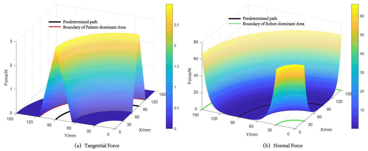
Figure 2Variation characteristics of the tangential force (a) and normal force (b) around the predetermined path.
The analytical Jacobian matrix of the robot is donated by Eq. (9); here, maps the joint velocities to the translational end-effector velocities, and maps to the rotational end-effector velocities:
For the force-field controller and end-effector rotational impedance controller, the desired control torque and can be computed by Eqs. (10) and (11), respectively. On this basis, robot motion in null-space is constrained (Hermus et al., 2022), and the desired null-space control torque is donated by Eq. (12).
Here, is the null-space projector and is defined as follows: . is joint-space stiffness, is joint-space damping and is a real-time joint position with the nominal joint position being constant throughout the trial. The desired assist torque can be represented as follows:
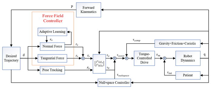
Figure 3 shows the overall block diagram of the proposed force-field-based robot rehabilitation system. The left side depicts the force-field control strategy mentioned in this paper, and the right side shows patient–robot interaction.
The experiments involved in this paper are conducted on an end-effector upper-limb rehabilitation robot (EULRR) platform (Zhang et al., 2020b, 2021, 2022; Sun et al., 2021) with real-time external torque control implemented via the FRI (Fast Research Interface) software package (Schreiber et al., 2010). Five healthy subjects (mean age of 26.2 years and a male to female ratio of 3:2) were recruited to participate in the following experiment. The experiment aims to verify the feasibility of the proposed force-field control strategy in rehabilitation training and to investigate the effect of different parameters on the control performance.
3.1 Hardware
EULRR is designed to mimic the relative position of the human arms for more effective rehabilitation training. Figure 4 describes the structure of EULRR, which includes a pair of industrial manipulators, an external monitor and the body with an electrical module, a pair of manipulator control cabinets, and a control computer.
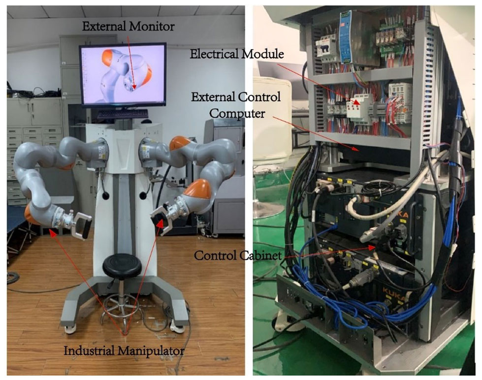
Figure 4Architecture and major components of the end-effector upper-limb rehabilitation robot (EULRR) system.
3.2 Experimental setup
During the test, the subject sat inside the EULRR and kept their torso still, as shown in Fig. 5. The subject's hand was connected to the end of the robot via a handle, with the assumption that the subject's left upper arm was the affected side. To verify the effectiveness of the force field in different areas, the subject had to cross two areas in one single experiment; therefore, a state of muscular spasticity (MS) was artificially constructed, which required the subject to complete the training with a large deviation. Subjects were required to intentionally manipulate the robot end-effector, circulating along the predetermined path for seven laps in every single experiment. During laps 2 to 4, the subjects were asked to complete the training task as well as possible in a muscle normal (MN) state; however, during laps 6 and 7, the training task was performed in the MS state. It is important to note that, in this paper, position deviation is the criterion used to distinguish acceptable or unacceptable training performance.
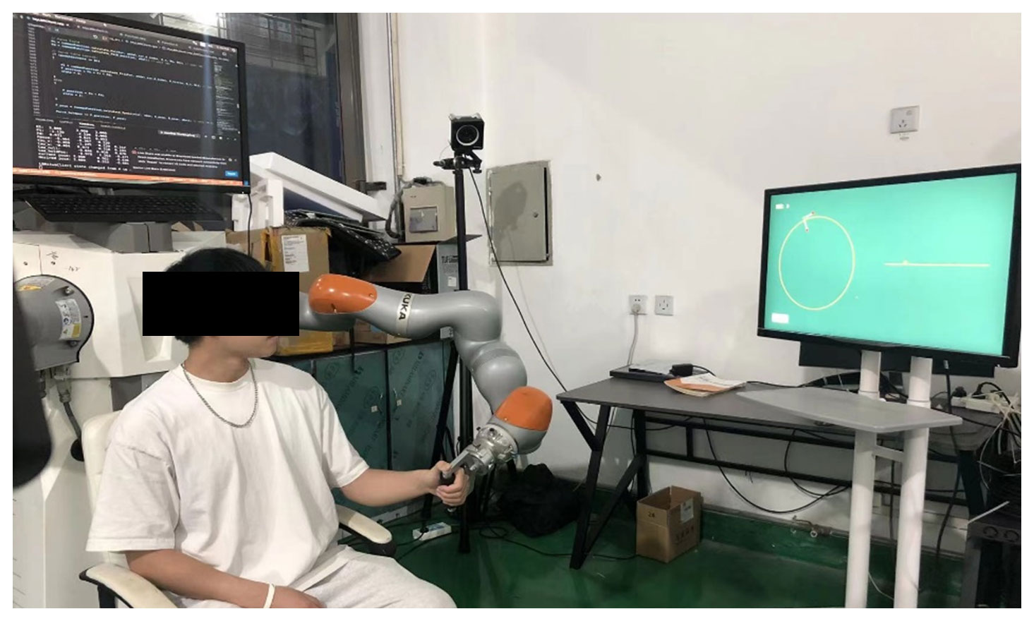
Figure 5Upper-limb rehabilitation robot with a healthy subject looking at the graphical guidance.
The experiments were designed under the principle of control variates. The fixed parameters of all of the sub-experiments are shown in Table 1. The first experimental group (E1 in Table 2) contains 12 conditions, named T1 to T12, and aims to investigate the effect of different combinations of KT and KD on the force-field control performance. The second experimental group (E2 in Table 2) contains three conditions, named T13 to T15, and aims to investigate the effect of different combinations of α and β on the force-field control performance. The third experimental group (E3 in Table 2) is the control group and has only one condition, named T16. The control group T16 is performed before all of the other groups.


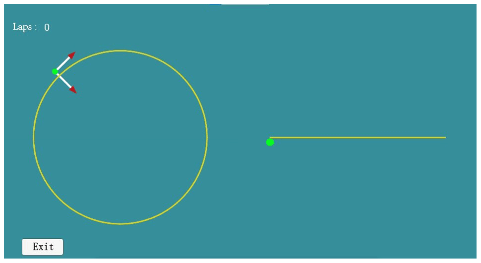
The system provides the subjects with visual guidance, developed based on Unity-3D, as shown in Fig. 6. The green dot on the interface is the real-time position of the end-effector, the arrows point out the real-time directions of the tangential and normal forces, the yellow circle is the top view of the predetermined path, the yellow line is the front view of the predetermined path, and the completed lap of the subject is recorded in the upper left-hand corner. The subject moves clockwise.
3.3 Data processing
The experimental data were all processed with MATLAB and SPSS software. The real-time position of the end-effector was calculated according to the robot forward kinematics. The position deviation of the end-effector was calculated using Eq. (1), and the assistance force of the robot was calculated using Eq. (14).
The actual path was visualized along with the predetermined path in order to intuitively point out the difference between robot-assisted movement and free movement, and the average assistance force was displayed along with the end-effector position deviation in order to intuitively discover their relationship. The abrupt engagement of the robot controller at the start of each experiment induced transient behavior in the robot end-effector motion, as the task was not critically damped. To eliminate possible transient behavior from the data analysis, the first revolution in each of these trials was discarded, and the fifth revolution was discarded as well because it recorded the transition behavior between two states, which was meaningless to the experiment.
3.4 Result
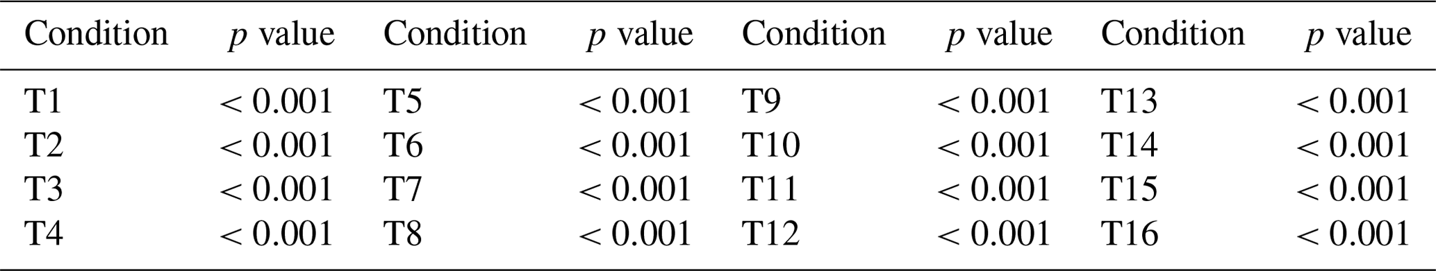
The actual path of the hand of the first subject (S1) under condition T14 and condition T16 are shown in Figs. 7 and 8, respectively. The red curves are conducted in the MN state, and the blue curves are conducted in the MS state. The actual paths conducted in the two states are significantly different: under condition T14, the average respective deviations in the MN and MS states are 6.51 and 19.35 mm, whereas those under condition T16 are 23.05 and 34.28 mm. By analyzing all five subjects' average deviations between the two states using a paired t test, significant differences between two states were uncovered, as shown in Table 3, which proves the feasibility of the MS state.
Table 3Paired t test results between the MN state and the MS state in each condition.
Even though the 3D view in Figs. 7 and 8 clearly shows the difference in the actual path between robot-assisted motion and the free motion, there is no significant distinction between them in the xoy view because the graphical guidance works, but it is difficult for the subject to balance the motion in both the xoy plane and the yoz plane at the same time, which results in greater deviation in the z-axis direction when the subjects are experiencing free movement. This is evident from the xoz or yoz view.

Figure 7The actual paths traveled by the hand of subject S1 under condition T14, showing (a) the 3D view of the paths as well as the (b) xoy, (c) yoz and (d) xoz views of the paths.
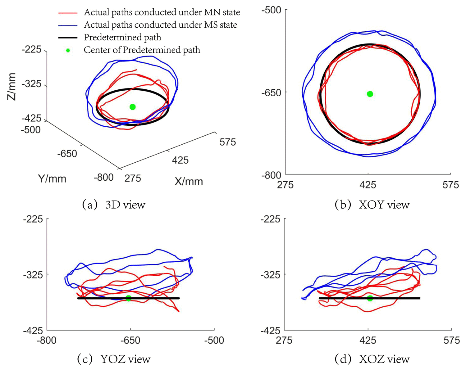
Figure 8The actual paths traveled by the hand of subject S1 under condition T16, showing (a) the 3D view of the paths as well as the (b) xoy, (c) yoz and (d) xoz views of the paths.
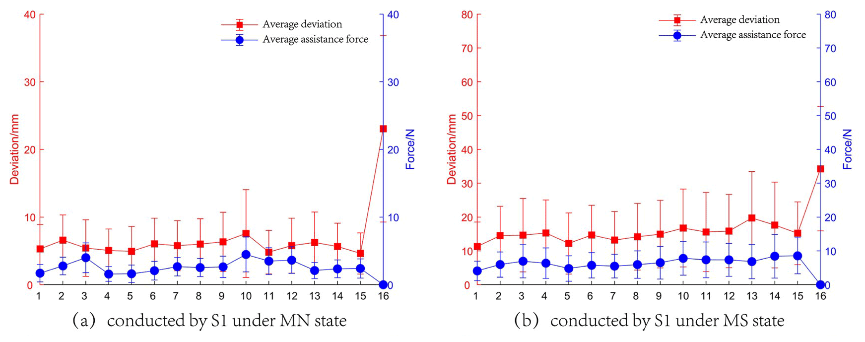
Figure 9The experimental results of the tests conducted by S1, showing (a) the average assistance force and deviation obtained in the MN state and (b) the average assistance force and deviation obtained in the MS state.
Table 4Paired t test results for the MN and MS states.
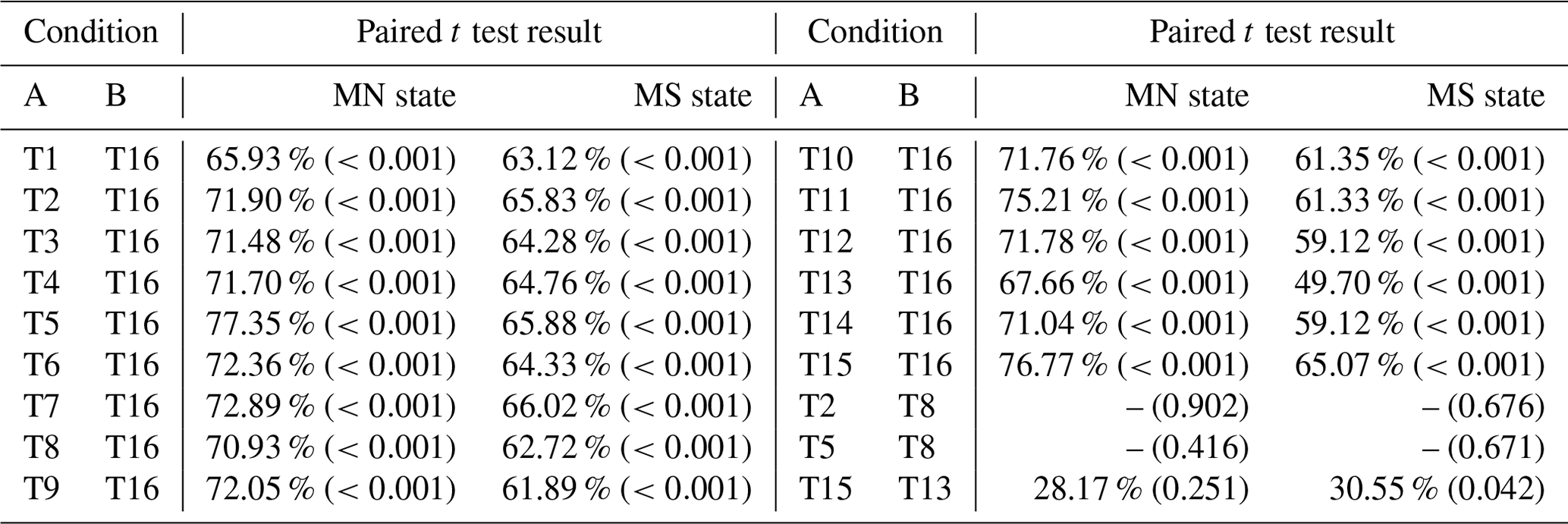
The percentages represent the reduction in the average position deviation of condition A compared with that of condition B.
The experimental results containing the average assistance force and deviation of the tests conducted by S1 are shown in Fig. 9. The effect of different combinations of control parameters can be revealed. The red line depicts the variation in the average deviation, while the blue line indicates the variation in the average assistance force. It can be noted that the presence of a force field causes the end-effector deviation to be smaller than that under free motion, regardless of whether the subject exercises in the MN state or the MS state. For each state, the results are statistically analyzed using a paired t test in order to compare the results between conditions. The threshold for the p value is selected to be 5 % for all tests. The results of the paired t test are shown in Table 4. If the t test result is shown with a “–”, it means that the mean deviation of the two sets of data is similar; otherwise, the percentage decrease is shown in the table with the p values given in parentheses. The main findings with respect to the paired t test results are as follows:
-
For the two states, conditions T1–T15 and condition T16 present significant differences in their mean deviation: all conditions show great improvements compared with condition T16, which proves that the force field can help subjects improve their training performance. Thus, the feasibility of force field for rehabilitation training is verified.
-
With respect to conditions group T2 and T8 and condition group T5 and T8, there is no significant difference in the mean deviation in either of these groups, resulting in similar performance.
-
In the MN state, conditions T13 and T15 have no significant difference in their mean deviation, although condition T15 shows a 28.17 % improvement compared with condition T13. However, in the MS state, a significant difference is shown between these treatments, despite the similar improvement in the mean deviation compared to that in the MN state. When the subject is in the MS state, a similar mean deviation improvement rate to that in the MN state represents a larger mean deviation, which can cause significant changes in the human–robot interaction. However, this may not change much in the MN state.
In experimental group E1, the variation in the assistance force and the deviation show the same trend when the characteristics of the normal force are controlled. However, there are still some cases where the assistance forces have opposite trends to the position deviations (e.g., condition T3 in Fig. 9a), and this can be explained by the fact that the average deviations in the MN state are small, with the contribution of the tangential force to the assistance force being much larger than that of the normal force. Nevertheless, when the subjects perform the tasks in the MS state, the position deviations are larger overall, and the effect of tangential force is smaller, resulting in the same trend between the average deviations and assistance forces. The above analysis indicates that the force field can respond effectively to the performance of the subject by applying time-varying and appropriate assistance force.
In experimental group E1-1, the average deviations have a different trend from KT when KD remains constant. This conclusion is also applicable to the comparison between different experimental groups – for instance, condition T4 in E1-2, condition T7 in E1-3 and condition T10 in E1-4 also show the same result. In contrast, for groups E1-2, E1-3 and E1-4, the value of KT remains constant, but the average deviations do not grow with an increase in KD. These two points combined with result (2) from the paired t test (shown above) indicate that KT and KD do not play a decisive role in the position constraint. However, as an increase in KT makes the subject's hand move faster, it is necessary to set an appropriate KD as a limitation for movement.
In experimental group E2, the values of KT and KD remain constant, and the variation characteristic of normal force is changed by adjusting the value of β. As the value of β increases, the average deviations gradually decrease, and the average assistance forces increase as well or are almost the same. In the other words, the subject is provided with a larger assistance force at the same position. Therefore, the constraint capacity of the force field is enhanced. The above conclusions combined with result (3) from the paired t test (shown above) provide evidence that the controller parameter should be adjusted in real-time according to the patient's motor performance.
This paper has dealt with the development of a minimal-intervention force-field-based control strategy for patient-cooperative control of an upper-limb rehabilitation robot that helps the patient to perform active rehabilitation in 3D space. The force field divides the space around the predetermined path and provides appropriate assistance to the patient according to position deviation during training in order to maximize the patient's effort. As the patient's hand gradually deviates from the predetermined path, the system increases the normal intervention to deter the patient from the predetermined path. When the patient's hand does not perform well with respect to moving along a predetermined path, selective assistance in the tangential direction can be applied to help the patient complete the task faster or as relaxation after intense training. The experimental results of five healthy subjects show that, for the predetermined training path, the force field could (1) help the subjects improve their rehabilitation performance, (2) respond effectively to the position deviation of the subjects, and (3) give the subjects time-varying and appropriate assistance force. Thus, the feasibility of force field use in rehabilitation has been verified. The experimental results also provide evidence that the controller parameter should be adjusted in real-time according to the patient's motor performance. Future works will be devoted to developing ADL paths to help patients perform specific motions and to recruiting patients for further trials.
The data that support the findings of this study are available from the corresponding author upon reasonable request.
JP and LZ conceived the idea, JP, LZ and QS performed all of the experiments. JP drafted the paper, and JP, LZ and QS discussed and edited the paper. JP finalized the paper, including preparing the detailed response letter. LZ and QS supervised the work.
The contact author has declared that none of the authors has any competing interests.
Publisher's note: Copernicus Publications remains neutral with regard to jurisdictional claims in published maps and institutional affiliations.
The authors are grateful to the anonymous reviewers and the editor for their comments and suggestions on improving our manuscript.
This research has been supported by the National Outstanding Youth Science Fund Project of the National Natural Science Foundation of China (grant no. 61973205).
This paper was edited by Wuxiang Zhang and reviewed by two anonymous referees.
Akiyama, Y., Yamada, Y., and Okamoto, S.: Interaction forces beneath cuffs of physical assistant robots and their motion-based estimation, Adv. Robotics, 29, 1315–1329, https://doi.org/10.1080/01691864.2015.1055799, 2015.
Andras, T., David, N., Mihaly, J., Istvan, M., Gabor, F., and Denes, Z.: Safe robot therapy: adaptation and usability test of a three-position enabling device for use in robot mediated physical therapy of stroke, in: 11th IEEE International Conference on Rehabilitation Robotics, Kyoto, Japan, https://doi.org/10.1109/icorr.2009.5209481, 2009.
Bertani, R., Melegari, C., De Cola, M. C., Bramanti, A., Bramanti, P., and Calabrò, R. S.: Effects of robot-assisted upper limb rehabilitation in stroke patients: a systematic review with meta-analysis, Neurol. Sci., 38, 1561–1569, https://doi.org/10.1007/s10072-017-2995-5, 2017.
Cortese, M., Cempini, M., Ribeiro, P. R. D., Soekadar, S. R., Carrozza, M. C., and Vitiello, N.: A Mechatronic System for Robot-Mediated Hand Telerehabilitation, IEEE-ASME T. Mech., 20, 1753–1764, https://doi.org/10.1109/tmech.2014.2353298, 2015.
Cui, X., Chen, W., Jin, X., and Agrawal, S. K.: Design of a 7-DOF Cable-Driven Arm Exoskeleton (CAREX-7) and a Controller for Dexterous Motion Training or Assistance, IEEE-ASME T. Mech., 22, 161–172, https://doi.org/10.1109/tmech.2016.2618888, 2017.
Erol, D., Mallapragada, V., Sarkar, N., and Taub, E.: A new control approach to robot assisted rehabilitation, in: 9th International Conference on Rehabilitation Robotics (ICORR), https://doi.org/10.1109/ICORR.2005.1501111, 2005.
French, J. A., Rose, C. G., O'malley, M. K., and ASME: System Characterization of MAHI Exo-II: A Robotic Exoskeleton for Upper Extremity Rehabilitation, 7th Annual Dynamic Systems and Control Conference, 2014, vol. 3, https://doi.org/10.1115/dscc2014-6267, 2014.
Frisoli, A., Salsedo, F., Bergamasco, M., Rossi, B., and Carboncini, M. C.: A force-feedback exoskeleton for upper-limb rehabilitation in virtual reality, Appl. Bionics Biomech., 6, 115–126, https://doi.org/10.1080/11762320902959250, 2009.
Gassert, R. and Dietz, V.: Rehabilitation robots for the treatment of sensorimotor deficits: a neurophysiological perspective, J. Neuroeng. Rehabil., 15, 46, https://doi.org/10.1186/s12984-018-0383-x, 2018.
Hermus, J., Lachner, J., Verdi, D., and Hogan, N.: Exploiting Redundancy to Facilitate Physical Interaction, IEEE T. Robot., 38, 599–615, https://doi.org/10.1109/tro.2021.3086632, 2022.
Hogan, N., Krebs, H. I., Charnnarong, J., Srikrishna, P., and Sharon, A.: MIT-MANUS: a workstation for manual therapy and training, in: Proceedings IEEE International Workshop on Robot and Human Communication, 161–165, https://doi.org/10.1109/ROMAN.1992.253895, 1992.
Jiang, X. Z., Huang, X. H., Xiong, C. H., Sun, R. L., and Xiong, Y. L.: Position Control of a Rehabilitation Robotic Joint Based on Neuron Proportion-Integral and Feedforward Control, J. Comput. Nonlin. Dyn., 7, 024502, https://doi.org/10.1115/1.4005436, 2012.
Kahn, L. E., Rymer, W. Z., and Reinkensmeyer, D. J.: Adaptive assistance for guided force training in chronic stroke, in: 26th Annual International Conference of the IEEE-Engineering-in-Medicine-and-Biology-Society, San Francisco, CA, 2722–2725, https://doi.org/10.1109/iembs.2004.1403780, 2004.
Keller, U., Rauter, G., and Riener, R.: Assist-as-needed path control for the PASCAL rehabilitation robot, in: 13th IEEE International Conference on Rehabilitation Robotics (ICORR), 24–26 June 2013, Univ. Washington Campus, Seattle, WA, https://doi.org/10.1109/icorr.2013.6650475, 2013.
Krebs, H., Ferraro, M., Buerger, S. P., Newbery, M. J., Makiyama, A., Sandmann, M., Lynch, D., Volpe, B. T., and Hogan, N.: Rehabilitation robotics: pilot trial of a spatial extension for MIT-Manus, J. Neuroeng. Rehabil., 1, 5, https://doi.org/10.1186/1743-0003-1-5, 2004.
Krebs, H. I., Palazzolo, J. J., Dipietro, L., Ferraro, M., Krol, J., Rannekleiv, K., Volpe, B. T., and Hogan, N.: Rehabilitation robotics Performance-based progressive robot-assisted therapy, Auton. Robot., 15, 7–20, https://doi.org/10.1023/a:1024494031121, 2003.
Leconte, P. and Ronsse, R.: Performance-based robotic assistance during rhythmic arm exercises, J. Neuroeng. Rehabil., 13, 82, https://doi.org/10.1186/s12984-016-0189-7, 2016.
Lee, S. H., Park, G., Cho, D. Y., Kim, H. Y., Lee, J. Y., Kim, S., Park, S. B., and Shin, J. H.: Comparisons between end-effector and exoskeleton rehabilitation robots regarding upper extremity function among chronic stroke patients with moderate-to-severe upper limb impairment, Sci. Rep.-UK, 10, 1806, https://doi.org/10.1038/s41598-020-58630-2, 2020.
Lindberg, P., Schmitz, C., Forssberg, H., Engardt, M., and Borg, J.: Effects of passive-active movement training on upper limb motor function and cortical activation in chronic patients with stroke: a pilot study, J. Rehabil. Med., 36, 117–123, https://doi.org/10.1080/16501970410023434, 2004.
Loureiro, R., Amirabdollahian, F., Topping, M., Driessen, B., and Harwin, W.: Upper Limb Robot Mediated Stroke Therapy – GENTLE/s Approach, Auton. Robot., 15, 35–51, https://doi.org/10.1023/a:1024436732030, 2003.
Malcolm, M. P., Massie, C., and Thaut, M.: Rhythmic Auditory-Motor Entrainment Improves Hemiparetic Arm Kinematics During Reaching Movements: A Pilot Study, Top. Stroke Rehabil., 16, 69–79, https://doi.org/10.1310/tsr1601-69, 2009.
Mehrholz, J., Hadrich, A., Platz, T., Kugler, J., and Pohl, M.: Electromechanical and robot-assisted arm training for improving generic activities of daily living, arm function, and arm muscle strength after stroke, Cochrane Db. Syst. Rev., 6, CD006876, https://doi.org/10.1002/14651858.CD006876.pub3, 2012.
Milot, M.-H., Spencer, S. J., Chan, V., Allington, J. P., Klein, J., Chou, C., Bobrow, J. E., Cramer, S. C., and Reinkensmeyer, D. J.: A crossover pilot study evaluating the functional outcomes of two different types of robotic movement training in chronic stroke survivors using the arm exoskeleton BONES, J. Neuroeng. Rehabil., 10, 112, https://doi.org/10.1186/1743-0003-10-112, 2013.
Mounis, S. Y. A., Azlan, N. Z., and Sado, F.: Assist-as-needed control strategy for upper-limb rehabilitation based on subject's functional ability, Meas. Control., 52, 1354–1361, https://doi.org/10.1177/0020294019866844, 2019.
Nef, T., Mihelj, M., and Riener, R.: ARMin: a robot for patient-cooperative arm therapy, Med. Biol. Eng. Comput., 45, 887–900, https://doi.org/10.1007/s11517-007-0226-6, 2007.
Proietti, T., Crocher, V., Roby-Brami, A., and Jarrasse, N.: Upper-Limb Robotic Exoskeletons for Neurorehabilitation: A Review on Control Strategies, IEEE Rev. Biomed. Eng., 9, 4–14, https://doi.org/10.1109/rbme.2016.2552201, 2016.
Schoone, M., Os, P. V., and Campagne, A.: Robot-mediated Active Rehabilitation (ACRE) A user trial, in: 10th IEEE International Conference on Rehabilitation Robotics, 477–481, https://doi.org/10.1109/icorr.2007.4428469, 2007.
Schreiber, G., Stemmer, A., and Bischoff, R.: The Fast Research Interface for the KUKA Lightweight Robot, in: IEEE workshop on innovative robot control architectures for demanding (Research) applications how to modify and enhance commercial controllers (ICRA 2010), May 2010, Anchorage, USA, Citeseer, 15–21, 2010.
Shi, D., Zhang, W., Zhang, W., and Ding, X.: Assist-as-needed attitude control in three-dimensional space for robotic rehabilitation, Mech. Mach. Theory, 154, 104044, https://doi.org/10.1016/j.mechmachtheory.2020.104044, 2020.
Shi, D., Li, L., Zhang, W., and Ding, X.: Field-Based Human-Centred Control on SO(3) for Assist-as-Needed Robotic Rehabilitation, IEEE Trans. Med. Rob. Bionics, 4, 785–795, https://doi.org/10.1109/tmrb.2022.3194372, 2022.
Song, A., Pan, L., Xu, G., and Li, H.: Impedance Identification and Adaptive Control of Rehabilitation Robot for Upper-Limb Passive Training, Foundations and Applications of Intelligent Systems, 691–710, https://doi.org/10.1007/978-3-642-37829-4_58, 2014.
Sun, Q., Guo, S., Zhang, L., and Fei, S.: Kinematic Dexterity Analysis of the Upper Dual Limb Rehabilitation Robot, International Journal of Mechatronics and Applied Mechanics, 29, 1029–1045, https://doi.org/10.17683/ijomam/issue9.3, 2021.
Todorov, E. and Jordan, M. I.: A Minimal Intervention Principle for Coordinated Movement, Proceedings of the 15th International Conference on Neural Information Processing Systems 2002, MIT Press, 2013.
Wang, C., Peng, L., Hou, Z.-G., Wang, W., and Su, T.: A Novel Assist-As-Needed Controller Based on Fuzzy-Logic Inference and Human Impedance Identification for Upper-Limb Rehabilitation, in: 2019 IEEE Symposium Series on Computational Intelligence (SSCI), IEEE, 1133–1139, https://doi.org/10.1109/ssci44817.2019.9002868, 2019.
Wu, Q., Wang, X., Chen, B., and Wu, H.: Development of a Minimal-Intervention-Based Admittance Control Strategy for Upper Extremity Rehabilitation Exoskeleton, IEEE T. Syst. Man. Cy.-S., 48, 1005–1016, https://doi.org/10.1109/tsmc.2017.2771227, 2018.
Xu, G., Song, A., and Li, H.: Control System Design for an Upper-Limb Rehabilitation Robot, Adv. Robotics, 25, 229–251, https://doi.org/10.1163/016918610x538561, 2011.
Zhang, L., Guo, S., and Sun, Q.: An Assist-as-Needed Controller for Passive, Assistant, Active, and Resistive Robot-Aided Rehabilitation Training of the Upper Extremity, Appl. Sci.-Basel, 11, 340, https://doi.org/10.3390/app11010340, 2020a.
Zhang, L., Guo, S., and Sun, Q.: Development and Assist-As-Needed Control of an End-Effector Upper Limb Rehabilitation Robot, Appl. Sci.-Basel, 10, 6684, https://doi.org/10.3390/app10196684, 2020b.
Zhang, L. G., Guo, S., and Sun, Q.: Development and Analysis of a Bilateral End-Effecter Upper Limb Rehabilitation Robot, J. Mech. Med. Biol., 21, 2150032, https://doi.org/10.1142/s0219519421500329, 2021.
Zhang, L. G., Guo, S., and Xi, J.: Performance-based assistance control for robot-mediated upper-limbs rehabilitation, Mechatronics, in press, 2022.