the Creative Commons Attribution 4.0 License.
the Creative Commons Attribution 4.0 License.
 | 20 Jul 2022
Stiffness analysis of a 3-DOF parallel mechanism for engineering special machining
Jianglong Tang
Changtao Yan
Guohua Cui
Minghui Zhang
Yan'an Yao
There are considerably rigorous requirements for accuracy and stability of the mechanism to accomplish large-scale and complex surface machining tasks in the aerospace field. In order to improve the stiffness performance of the parallel mechanism, this paper proposes a novel three degrees of freedom (DOF) redundantly actuated 2RPU-2SPR (where R, P, U and S stand for revolute, prismatic, universal and spherical joints, respectively) parallel mechanism. Firstly, the kinematics position inverse solution is derived and a dimensionless generalized Jacobian matrix is established through the driving Jacobian matrix and constraint Jacobian matrix. Secondly, the stiffness model of the parallel mechanism is deduced and the accuracy of the stiffness model is verified through finite-element analysis. Using eigenscrew decomposition to illustrate the physical interpretation of the stiffness matrix, the stiffness matrix is equivalent to six simple screw springs. Finally, the simulation experiment results demonstrate that redundantly actuated parallel mechanism has better stiffness performance compared to the traditional 2RPU-SPR parallel mechanism.
- Article
(9028 KB) - Full-text XML
- BibTeX
- EndNote


In the field of industrial manufacturing, the processing equipment with the parallel mechanism has been widely used and researched because of its excellent performance. Tian et al. (2019) proposed a novel robot leg deformable parallel mechanism with the ability of reconstruction and motion change based on an innovative rotatable-axis revolute joint. Araujo-Gómez et al. (2019) carried out kinematic analysis and size optimization of 2R2T (where R and T stand for rotational and translational degrees of freedom, respectively) parallel mechanism. Wu et al. (2014) systematically introduced and discussed a series of 2-DOF parallel manipulators with equal–diameter spherical pure rotation. Three-DOF parallel mechanism is one of the most noticeable and widespread mechanisms and Li and Hervé (2010) synthesized a series of 3-DOF parallel mechanisms. The finite motions of 1T2R parallel mechanisms with parasitic motions were described and analyzed by Sun and Huo (2018) and their topologies were synthesized. Huang et al. (2019) proposed a simple and highly visual method for type synthesis of families of over-constrained parallel mechanisms with one translational and two rotational motion capabilities. In order to expand the application of parallel manipulators, Wu et al. (2018) created a 5-DOF hybrid machine and a mechatronics model was derived based on this parallel manipulator.
Stiffness design refers to optimization based on a certain stiffness analysis model with structural parameters as variables to improve the stiffness performance of the mechanism. A stiffness synthesis strategy was proposed for the desired elastic center of a 3-DOF parallel mechanism composed of 3RPR links (Wen et al., 2015). The Exechon parallel mechanism with over-constrained kinematic chain has attracted extensive attention in the research community and its stiffness has been studied by Zhang et al. (2016). Moosavian et al. (2016) introduced a method for designing variable geometry parallel mechanism with enhanced static properties. Generally, higher stiffness allows greater variable load and higher precision of the end–effector. There is no unified strategy to establish the stiffness model of the parallel mechanism and many experts have done relevant research on different types of parallel mechanisms. A new variable stiffness design method was proposed to optimize the geometric parameters of the parallel mechanism by Li et al. (2017). For the heavy-duty parallel robot manipulator, Wang et al. (2017) proposed a method to simultaneously optimize the size and structural parameters and introduced a stiffness performance evaluation index. This stiffness distribution index mainly focuses on the stiffness components of the manipulator. Moosavian et al. (2014) introduced a new method to enhance the stiffness of parallel mechanisms without redundant actuation. Chen et al. (2018) showed a negative stiffness criterion for active stiffness using the example of a redundantly actuated planar parallel mechanism. Ali et al. (2018) also studied the stiffness of the parallel mechanism. Moreover, the over-constrained parallel mechanism can also be more widely applied by combining with sliding rail such as the serial parallel hybrid 5-axis machining machine tool. In order to meet the requirements of the large workspace and high dexterity of aerospace industry processing equipment, Fang et al. (2020) and Jiang et al. (2021) proposed a new type of series–parallel hybrid processing robot mechanism. Portman (2020) presented a new method to define stiffness values for elastic support systems and demonstrated the effectiveness and generality of the method with examples of simulated applications. Cao et al. (2017) summarized a method for modeling stiffness of a 3R2T over-constrained parallel robot mechanism. The proposed method can be conveniently applied to build stiffness models with high accuracy for 3R2T over-constrained parallel mechanisms. Jiang et al. (2019) designed a 3T2R parallel mechanism with a large output rotation angle in terms of the Lie group theory and the integration of configuration, and analyzed various performance indices of the parallel mechanism.
The commonly used modeling methods at this stage can be roughly divided into two categories. One is the employ of some methods such as principle of virtual work, structural matrix, screw theory or a combination of them. Based on strain energy analysis and screw theory, Cao et al. (2017) proposed a systematic approach to a limb stiffness model that considers the coupling of constrained wrench stiffness and actuated wrench stiffness, and Sun et al. (2016) proposed a 2-DOF constrained rotating parallel mechanism with an articulated walking platform and established its stiffness model. Yan et al. (2016) performed a stiffness analysis using a strain energy method that considers compliance of the mobile platform. Wu et al. (2022) proposes a novel method to evaluate the dynamic performance of the robot along joint–space directions. Furthermore, a new stiffness index is proposed to evaluate stiffness properties. Fang et al. (2002) proposed a comprehensive method of 4-DOF parallel mechanism based on the screw theory and summarize a comprehensive method of 3R parallel mechanism. Gosselin and Schreiber (2018) considered two types of redundancy for parallel mechanisms, namely, actuation redundancy and motion redundancy. Then, each concept was mathematically formulated to clearly demonstrate their characteristics and properties. The other is with the help of commercial software. Combined with related theoretical and experimental research, a finite-element analysis model of mechanism stiffness was derived. A novel method for force analysis of the over-constrained parallel mechanisms was proposed by Xu et al. (2015) and the correctness of the proposed method for force analysis is effectively verified based on Adams simulation software. Zhang et al. (2019) verified the analytical results of kinematics and dynamics through the co-simulation solution of Simulink and Recurdyn. Cao and Ding (2018) proposed a general method for solving 3R2T parallel mechanisms with complex structures and multiple redundant constraints, and then verified the correctness of the established stiffness model through finite-element analysis.
The main contribution of this paper is as follows: a novel redundantly over constrained 2PRU-2SPR parallel mechanism is presented. What is more, the relationship between the pose of moving platform and external load is derived and the overall stiffness matrix of the mechanism is obtained. To have a deeper understanding of the internal structure of stiffness matrix, an eigenscrew decomposition method is utilized to illustrate the physical interpretation of stiffness matrix that can be expressed as linear superposition of simple springs based on the screw decomposition. Finally, the stiffness modeling and analysis methods are effective and correct after proving by finite-element software analysis, and the stiffness performances are compared with the traditional 2RPU-SPR parallel mechanism.
Table 1Relevant concepts associated with stiffness analysis of parallel mechanism.

2.1 Configuration of 2RPU-2SPR parallel mechanism
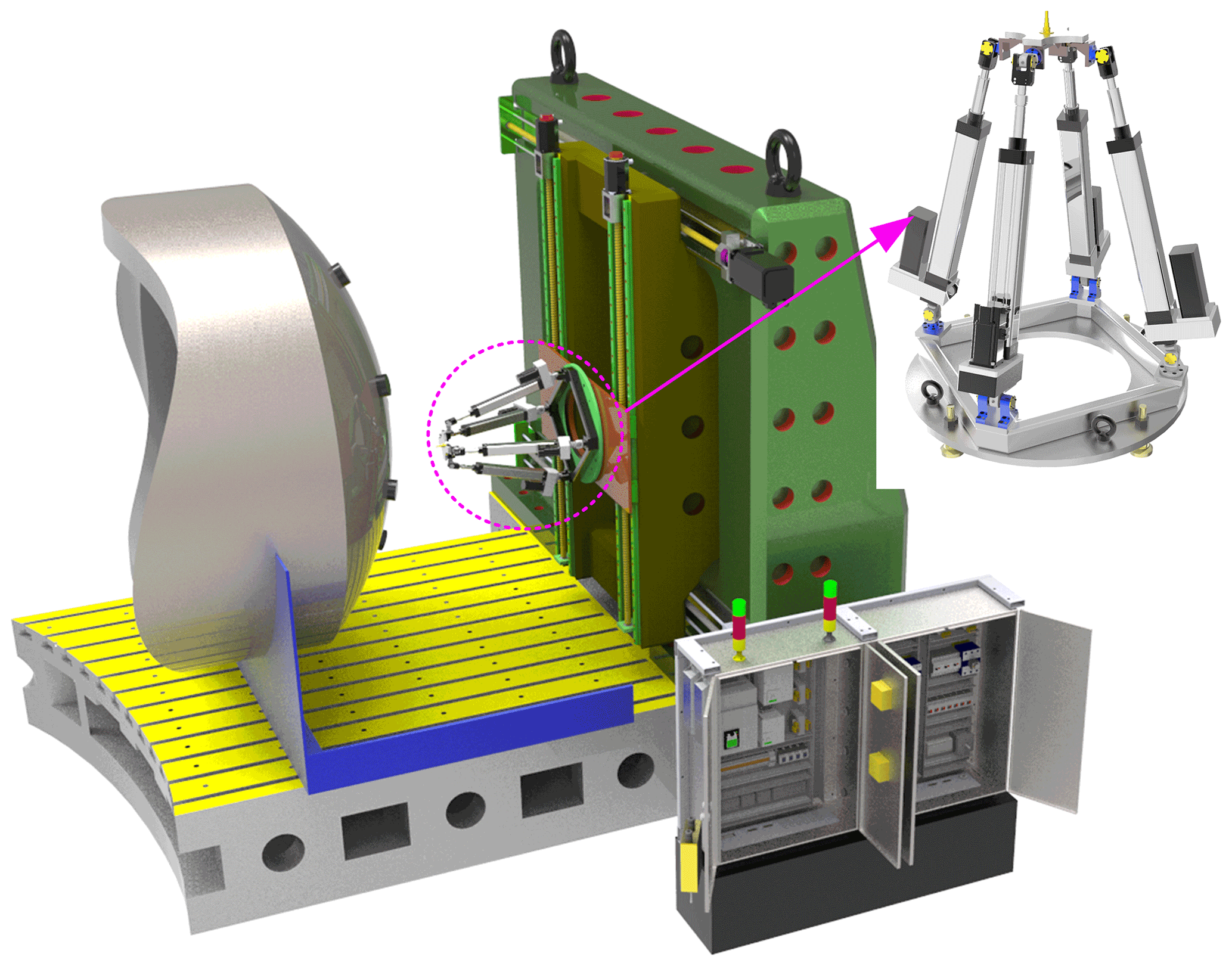
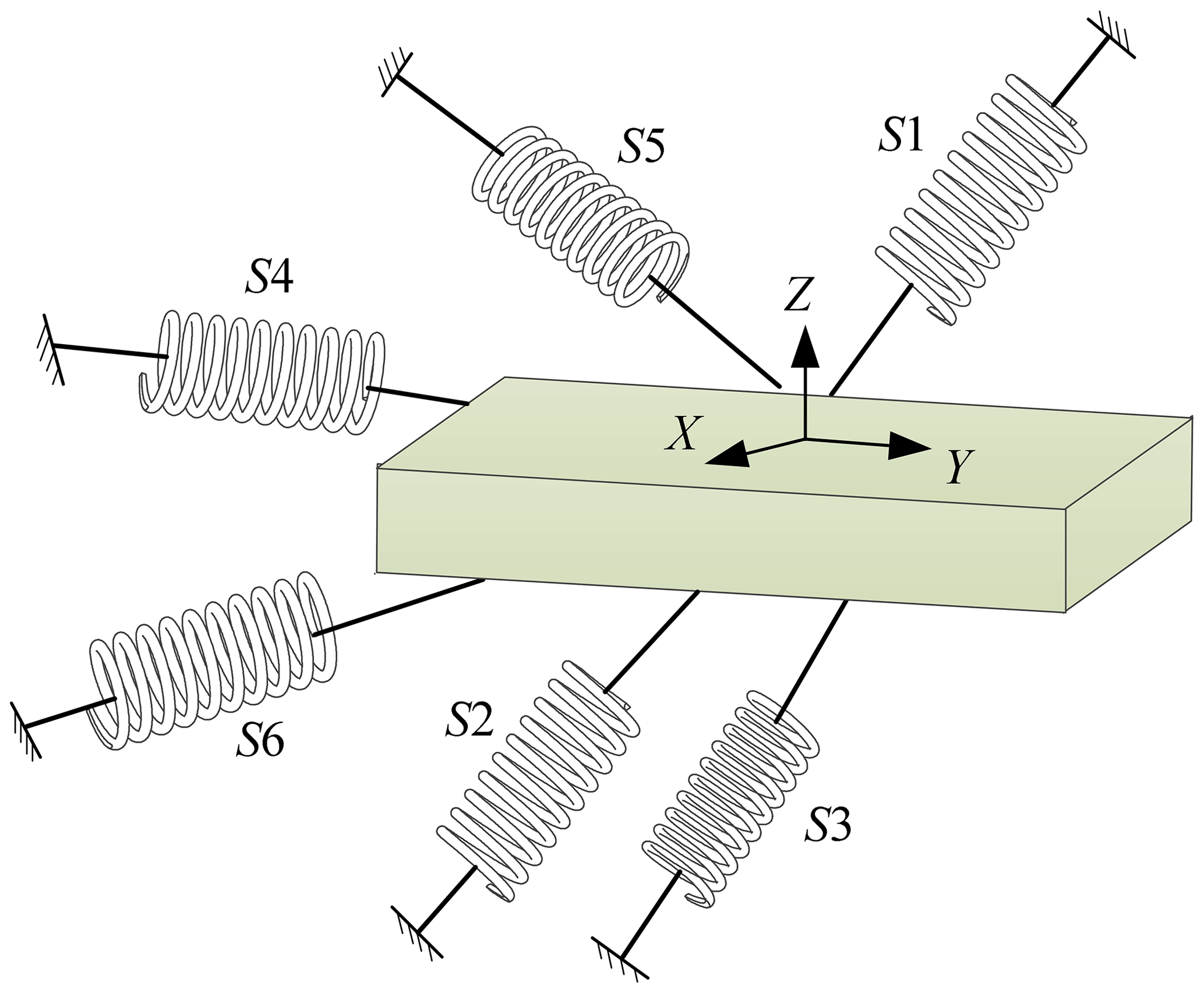
In order to meet the processing requirements of large complex special-shaped workpiece, an over-constrained 2RPU-2SPR redundantly actuated parallel mechanism is applied to the machine tool equipment combined with the characteristics of parallel mechanism and the purpose of machining complex curved surface. The over-constrained parallel mechanism not only has the characteristics of parallel mechanism but also has the advantages of high stiffness, high precision, strong carrying capacity and avoiding singularity. Wu et al. (2013) revealed the relationship between the stiffness performance index of the parallel manipulator and its natural frequency through the study of a 3-DOF parallel manipulator. And the simulation results demonstrate that additional redundant legs can increase the natural frequency of the parallel mechanism and improve the stiffness performance. As shown in Fig. 1, the 2RPU-2SPR parallel mechanism is mainly composed of a fixed platform, a moving platform, an end effector, and two joints of actuated branches with identical structures and symmetrically arranged. The fixed platform is connected with the moving platform through the two joints of actuated branches. One joint of branches is RPU moving branch chain including a revolute joint, a prismatic joint and a universal joint. The other joints of branches are SPR moving branches including a spherical joint, a prismatic joint and a revolute joint.
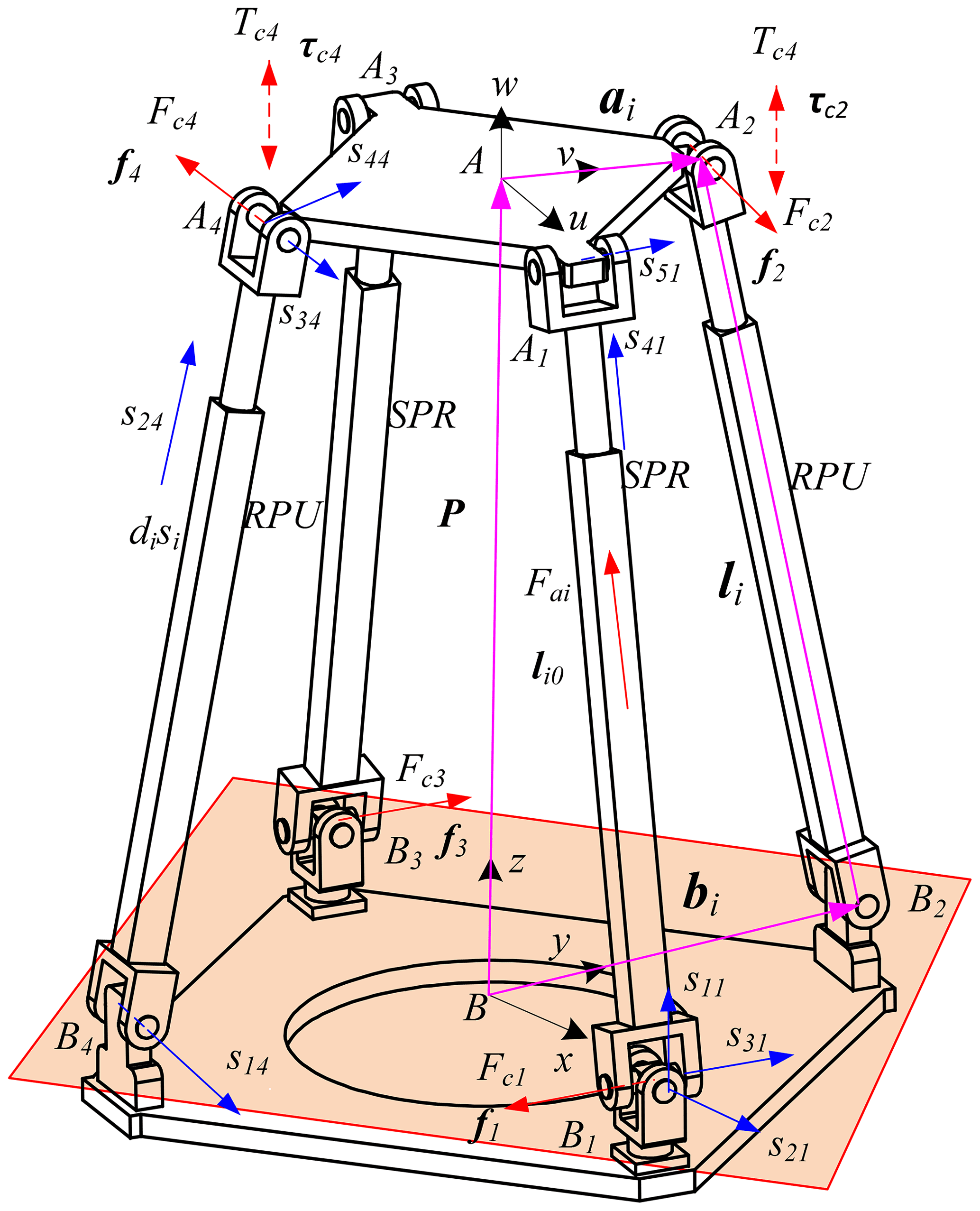
As shown in Fig. 2, the coordinate system is established on the structure diagram of the over-constrained parallel mechanism so as to facilitate the later modeling and optimization calculation. With B as the center, a fixed coordinate system B-xyz is established on the mechanism baseB1B2B3B4 in which the directions of the x axis and y axis are coincident to BB1 and BB2, and the direction of the z axis is determined according to the right-hand rule. The coordinate system A-uvw attached moving platform A1A2A3A4 is established with origin A as the geometric center of mechanism, and the directions of the u axis and v axis on the coordinate system are coincident to AA1 and AA2, and the w axis is determined according to the right-hand rule. sij indicates the direction of the rotation axis or the movement axis of the kinematic joints.
2.2 Degree of freedom analysis
According to the screw theory, the constraint force and constraint moment on each kinematic branch chain do no work on the center of the moving platform, that is,
where Fci (i=1, 2, 3, 4) is the constraint force on each branch, fi is its direction vector, v and w are the axis directions of the A–uvw coordinate system, li is the direction vector of the driving limb, ai is the joint vector in the fixed coordinate system, and Tci is the constraint moment on two and four branches whose direction vector is τi.
Equations (1) and (2) are written into matrix form and the relationship between constraints is as follows:
Jc is the constrained Jacobian matrix and the specific elements are as follows:
It is known that the Kutzbach degree of freedom calculation formula is as follows:
where F represents the degree of freedom of the mechanism, n represents the number of mechanism components, g represents the number of kinematic joints, represents the order of the mechanism, fi represents the degree of freedom of the i kinematic joint, v represents the redundant constraint of the mechanism and ς represents the local degree of freedom.
Since there is neither constraint couple with the same direction nor coaxial constraint force in the constraint screw of the mechanism, the mechanism has no common constraint, i.e., λ=0. Since the mechanism has no local degrees of freedom, i.e., ς=0, it is easy to know from Eq. (4) that the constrained Jacobian matrix Jc has three linearly independent terms so the mechanism has three redundant constraints, i.e., v=3. It can be seen from the mechanism diagram that the number of mechanism member n, kinematic joints g and relative degrees of freedom of all motion joints fi are 10, 12 and 18, respectively.
The degree of freedom of the parallel mechanism can be obtained by substituting Eq. (5):
The parallel mechanism studied in this paper has three degrees of freedom which can rotate around two axes and move along one axis, namely, x axis, v axis and z axis, respectively. It is worth noting that the number of actuating joints of the parallel mechanism is four, resulting in the number of actuating joints of the parallel mechanism being greater than the number of DOF. Therefore, the mechanism is a redundantly actuated over-constrained parallel mechanism.
3.1 Position inverse solution
Set R as the rotation matrix of the moving coordinate system relative to the fixed coordinate system:
where R(γ,z) represents rotation around z axis for γ, R(β,y) represents rotation around y axis forβ and R(α,x) represents rotation around x axis for α. Symbol c represents cos and s represents sin which will not be repeated later.
Assuming that the moving platform A1A2A3A4 and the fixed platform B1B2B3B4 are squares with circumscribed circle radii of ra and rb, respectively, the equation of AiBi vector in B-xyz is established by using the closed vector method as follows:
where represents the position vector of the origin A of the moving platform coordinate system in the fixed coordinate system B-xyz, ai and bi are the position vectors of Ai and Bi hinge points in the fixed coordinate system, respectively, and their coordinates are respectively expressed as follows:
where .
The inverse position solution of Eq. (8) can be expressed as follows:
Equation represents the Euclidean norm of the driving limb.
Due to the introduction of the rotating joint R, four constraint equations can be obtained, namely,
Equation (11) is organized as follows:
3.2 Jacobian matrix of parallel mechanism
Assuming that the velocity vector of the moving platform reference point A is v and the angular velocity vector of the moving platform is w, the hinge point between the driving limb and the moving platform is Ai and the velocity vector vai of the hinge point is expressed as follows:
Then, the axial speed along the driving limb li0 can be expressed as follows:
In matrix form, it can be expressed as follows:
where J0 is the generalized Jacobian matrix, Ja is the actuated Jacobian matrix and Jc is the constrained Jacobian matrix of the mechanism.
Combining Eqs. (14) and (15), the generalized Jacobian matrix J0 of the mechanism can be expressed as follows:
According to the dual relationship between velocity mapping and force mapping, the force mapping relationship between each branch of the mechanism and the moving platform can be obtained from Eq. (16).
where , . Matrix τ is the external force F and external torque M acting on the reference point of the moving platform, and matrix f is the actuating force fa and constraint force fc on the branch chain.
The five-coordinate hybrid machine tool has high requirements for the kinematic and static properties of the mechanism when performing high-speed milling tasks in the aerospace field, so the stiffness analysis and optimization design is the key content that must be considered in the mechanism design.
When constructing the stiffness analytical equation of 2RPU-2SPR over constrained parallel mechanism, it does not lose generality. Firstly, the moving and fixed platforms of the parallel mechanism are regarded as ideal rigid bodies and it is assumed that the deformation of other parts belongs to the category of linear elasticity and small deformation, ignoring the small deformation of revolute, spherical and universal joint. The unit actuating force screw and unit constraining force screw applied each branch at the center point A of the moving platform are represented by Sai, Sri, and their amplitudes are represented by fai, fri, i=1, 2, 3 and 4, respectively. The unit constraint couple screw and amplitude of the second and fourth branches to the moving platform are Sτi, fτi (i=2, 4) but they can be decomposed into constraining couple helices along and perpendicular to the limb direction.
4.1 Modeling and analysis of branch stiffness
According to the basic knowledge of material mechanics, non-rigid parts will produce various deformations under different types of forces, so it is assumed that the tensile deformation of each branch under the driving screw Sai, fai is δai and the deflection along the binding axis under the wrench screw Sri, fri is δri. Under the restraining couple screw Sτj, fτj, the branches 2 and 4 produce a torsional deformation of δθi1 along the limb axis li0 and a bending deformation of δθi2 along the direction li0 perpendicular to the limb axis.
The specific relationship between force and deformation and stiffness coefficient is as follows:
where E is the elastic modulus, A is the cross-sectional area of the limb, kai is the tensile and compressive stiffness coefficient of the branch limb, Iz is the section moment of inertia, kri is the bending stiffness coefficient, G is the shear modulus and Ip is the polar inertia, , ,
The above formula is expressed in matrix form as follows:
where ,
,
.
4.2 Equivalent stiffness matrix of 2RPU-2SPR parallel mechanism
According to the above analysis, the elastic deformation vector generated by the actuating branch and moving platform under the constraint force and actuating force of each branch can be expressed as follows:
where ΔX means the deformation of the end effector,
,
Substituting Eqs. (22) and (23) into Eq. (17)
Then, the stiffness matrix of the parallel mechanism is as follows:
5.1 Linear stiffness and angular stiffness index
If the parameters and pose of the mechanism are given, the stiffness matrix of the mechanism will be determined and some stiffness indices can be defined to evaluate the stiffness characteristics of the mechanism. It should be noted that the parallel mechanism designed in this paper is mainly applied to the machine tool performing milling operation. Therefore, the linear stiffness and angular stiffness can be defined as follows:
kx, ky and kz are the linear stiffness along the x, y and z axis, respectively; kw is the torsional stiffness about w axis.
Table 2Geometric parameters, configuration parameters and physical parameters.

According to the structural parameters, position parameters and physical parameters given in Table 2, the stiffness matrix of the mechanism under this typical posture can be expressed as follows:
where the units of terms are N m−1 for K11, K22 and K33, and Nm rad−1 for K44, K55 and K66.
5.2 Static stiffness finite-element simulation
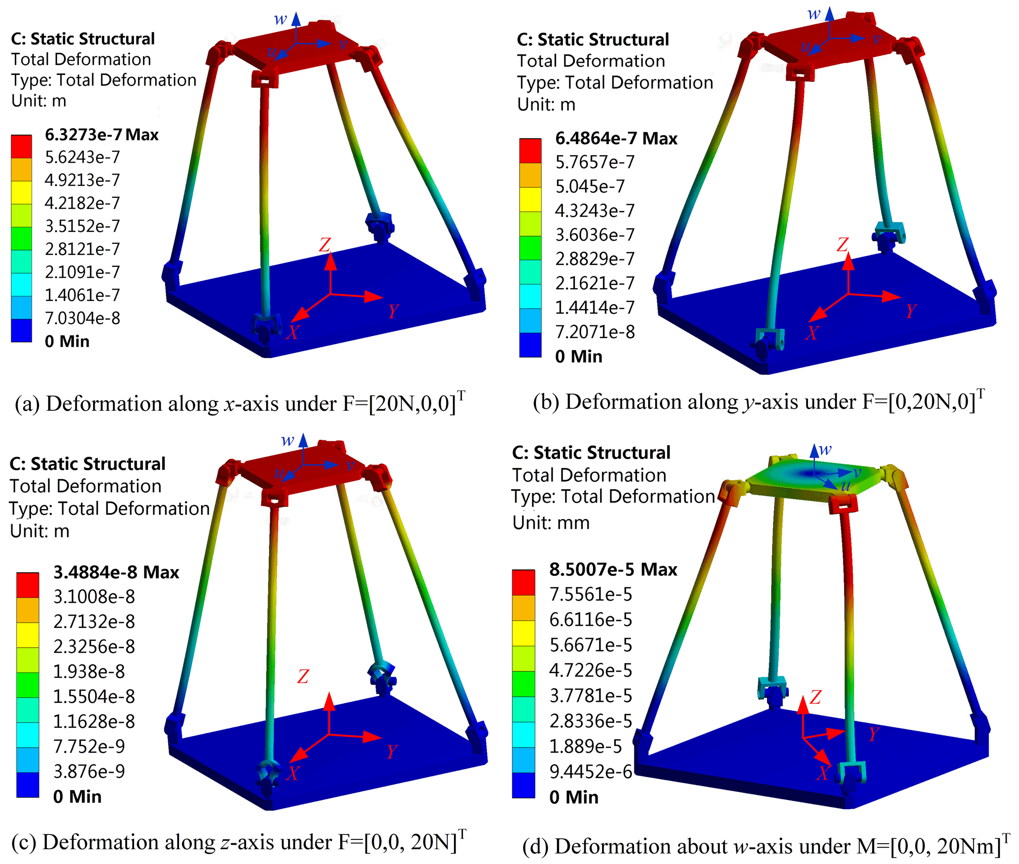
In order to testify the correctness and effectiveness of the stiffness model, finite-element analysis of the parallel mechanism is also conducted. The finite-element analysis of the parallel mechanism is carried out by employing the Ansys Workbench software. Figure 3a–c show the deformation of the parallel manipulator under force along the direction of x axis, y axis and z axis, respectively. Figure 3d is the deformation of the parallel manipulator under the moment about the direction of z axis.
The results obtained by the analysis calculation and finite-element analysis are listed in Table 3. Clearly, the results obtained by the finite-element analysis are very consistent with the results of analysis calculation. FEA is the abbreviation of finite-element analysis.
Table 3The results of calculation and finite-element analysis.

Under the premise of ignoring the deformation of the kinematic joint, the calculation results of the analytical model and the finite-element analysis model are very similar. The error of kx is 3.9 %, the error of ky is 6.3 %, the error of kz is 0.5 %, the error of kw is 1.75 % and the error range is within 0.5 %–6.3 %. Therefore, the established analytical model for the stiffness of the whole machine is effective and can be used for the study of the static stiffness characteristics of the parallel mechanism.
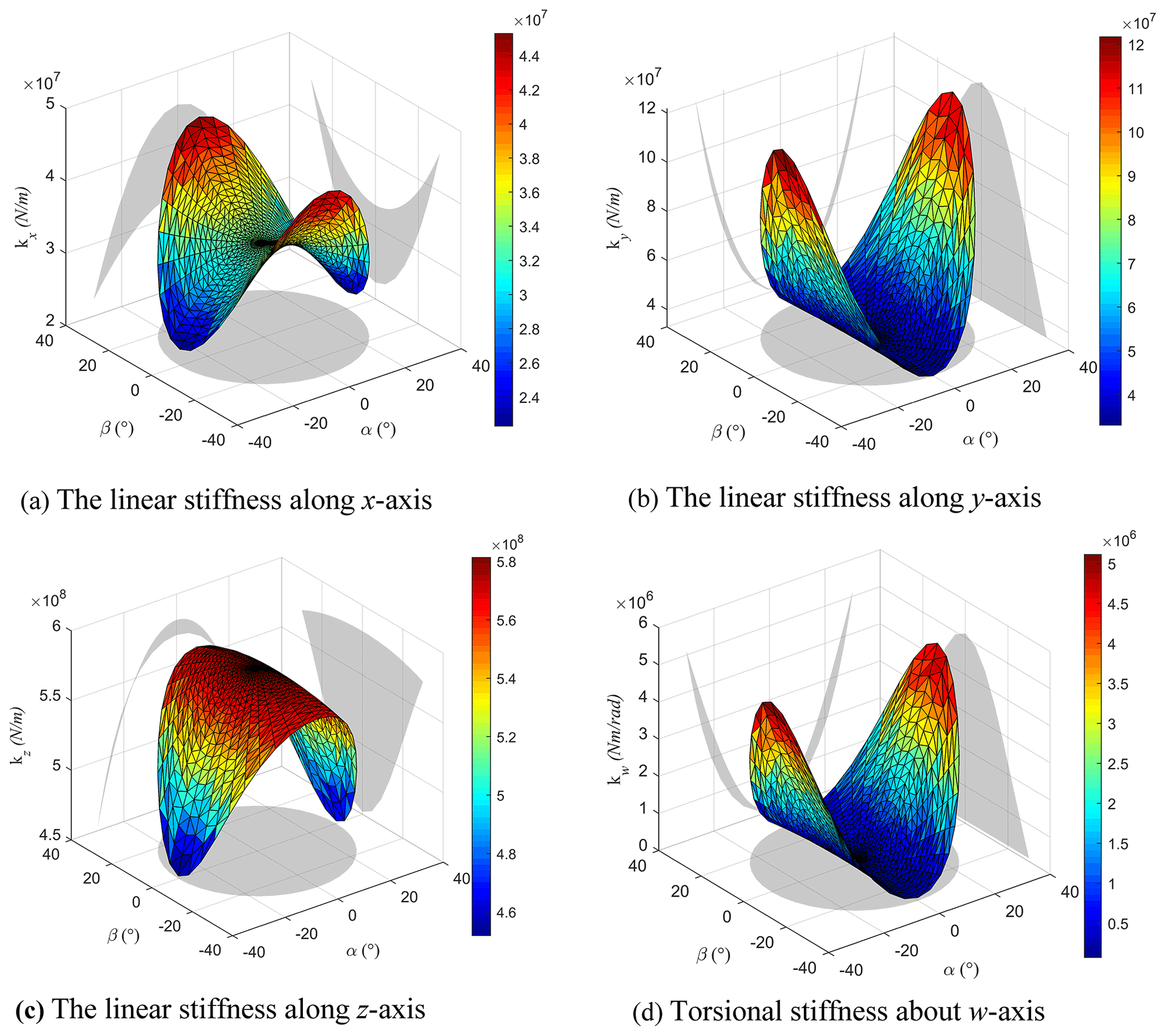
Assuming that the dynamic and static platforms are rigid bodies and ignoring the deformation of the moving pair, the calculation results of the analytical model and the finite-element model are very close. Therefore, the established stiffness analytical model is effective and it can be used for static stiffness analysis. In addition, the workspace is defined as , . The anisotropic deformation cloud diagram of the virtual prototype under the initial pose is depicted in Fig. 4.
5.3 Eigenvalue decomposition of stiffness matrix
Normally, the end deformation ΔX is expressed in the axis coordinate system while the eigenscrew is generally expressed in the ray coordinate system. In order to ensure the consistency of coordinate system, the Δ matrix is required to convert the axis coordinate system to the ray coordinate system, i.e.,
where E is the identity matrix.
Therefore, the decomposition of the stiffness matrix is transformed into the decomposition of the KΔ matrix, i.e.,
where λ and e represent the eigenvalues and eigenvectors of KΔ, respectively. So, the stiffness matrix can be expressed as follows:
where , , , em is eigenvector of KΔ, wm is unit screw of em, hm represents the pitch of wm, nm is direction vector of wm and ρm is position vector of wm relative to the original coordinate system.
The eigenscrew decomposition is applied to the stiffness matrix K as described in Eq. (30). By applying matrix transformation for solving the eigenscrew problem, the six eigen stiffness λm, the eigenscrew pitches hm and the eigenscrew wm are derived as shown in Eq. (31):
The physical interpretation of stiffness matrix K based on eigenscrew decomposition is elaborated in Table 4, which indicates that K can be interpreted by six screw springs. The directions along the eigenscrew of K are shown in Fig. 5. pm represents the pitch of the screw joint.
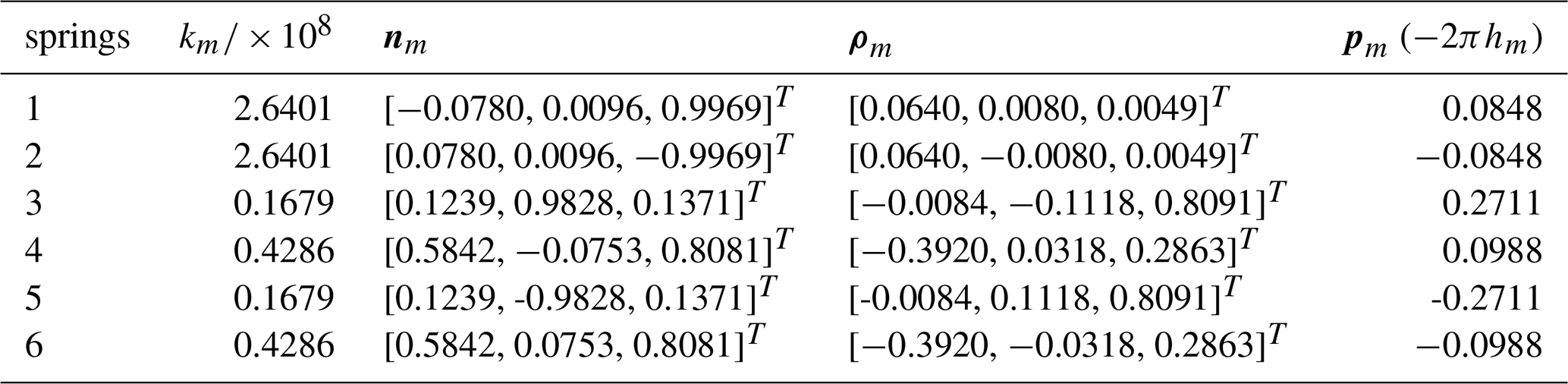
It can be seen from Table 4 and Fig. 5 that the stiffness matrix can be equivalent to a simple superposition of six springs. Six springs can be divided into three groups. Two springs in each group meet at one point which has the same spring stiffness and the pitches are opposite numbers. Since the mechanism has two branches that are not the same from each other, the mechanism does not show a certain symmetry and the resulting spring distribution is not regular.
5.4 Stiffness index at different heights
In order to evaluate the stiffness of some positions in the workspace, the maximum eigenvalues of the stiffness matrix K are employed as the evaluation index of the parallel machine tool.

It can be seen from Fig. 6 that the stiffness values of mechanism decrease with the increase of z value and the manipulator approaches singularity when approaching the workspace boundary. The lowest value of the maximum stiffness appears near the workspace boundary. Therefore, the minimum value of stiffness appears near the workspace boundary.
5.5 Stiffness comparison analysis
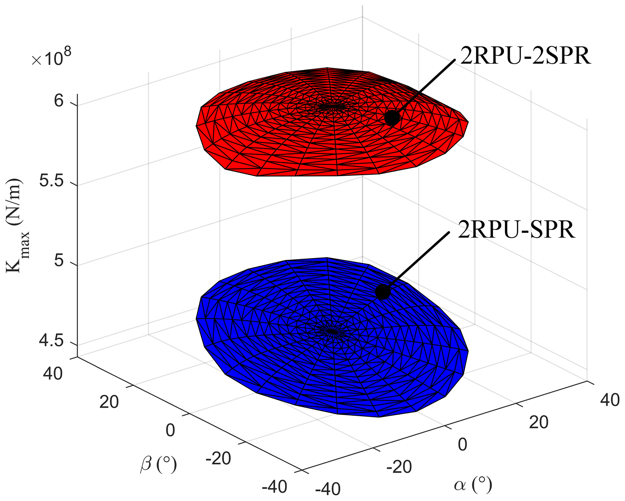
It is obvious from Fig. 7 that the kinematic performance of redundantly actuated 2RPU-2SPR parallel mechanism is better than traditional 2RPU-SPR parallel mechanism which has a bright engineering practical prospect. Therefore, the introduction of redundant branch chain can effectively improve the kinematic performance of 2RPU-SPR parallel mechanism which lays a theoretical foundation for later optimization design.
Taking the 2RPU-2SPR over-constrained parallel mechanism applied to complex surface machining as the research object, it starts from the mechanism characteristic description and the DOF characteristics. The position mapping relationship between the input member and the output member is established and the Jacobian matrix representing the velocity mapping relationship between the input joint and the output joint of the mechanism is obtained. It is worth noting that the stiffness performance of the parallel mechanism directly determines the motion accuracy and stability of the system when the mechanism performs the surface machining task. Based on the screw theory, the stiffness of the 2RPU-2SPR over-constrained parallel mechanism is deduced. Then the eigenscrew decomposition method can be adopted to decompose the stiffness matrix.
In this study, aiming at the large-scale and complex surface machining tasks in the aerospace field, a novel over-constrained redundantly actuated parallel mechanism is proposed. Furthermore, the correctness of the derivation of the stiffness matrix through finite-element simulation analysis is verified which can be used to study the static stiffness characteristics of the parallel mechanism. Simultaneously, the stiffness matrix is equivalent to three groups of springs with more definite physical meanings. Finally, compared with the stiffness of the 2RPU-SPR parallel mechanism, the passive over-constrained parallel mechanism has higher stiffness, indicating that the introduction of the redundantly actuated over-constrained branch chain SPR can improve the stiffness performance of the mechanism and can also effectively improve the stiffness distribution of the mechanism.
In our future research, the mechanism proposed in this paper has great stiffness performance; it can be connected with x and y sliding rail to form a five-axis hybrid processing machine tool which has a wider range of applications. What is more, the theoretical design and analysis proposed in this paper mainly focus on the parallel mechanism. There is no complete digital virtual simulation and test prototype construction for the overall complex surface intelligent processing equipment. The control theory is limited to the parallel mechanism and further research is needed on the overall control of the hybrid mechanism.
All the data used in this article can be made available upon reasonable request. Please contact the corresponding author (hqzhang@sdust.edu.cn).
HZ proposed the novel parallel robot and developed the theoretical analysis; JT and CY wrote the manuscript draft under the guidance of HZ; and GC, MZ and YY supervised the whole research work.
The contact author has declared that none of the authors has any competing interests.
Publisher's note: Copernicus Publications remains neutral with regard to jurisdictional claims in published maps and institutional affiliations.
The authors would like to acknowledge the financial support of the Fundamental Research Funds for Shanghai Collaborative Innovation Center of Intelligent Manufacturing Robot Technology for Large Components under grant no. ZXP20211101 and Key Laboratory of Vehicle Advanced Manufacturing, Measuring and Control Technology (Beijing Jiaotong University), Ministry of Education, China.
This research has been supported by the Fundamental Research Funds for Shanghai Collaborative Innovation Center of Intelligent Manufacturing Robot Technology for Large Components (grant no. ZXP20211101) and Key Laboratory of Vehicle Advanced Manufacturing, Measuring and Control Technology (Beijing Jiaotong University), Ministry of Education, China.
This paper was edited by Wuxiang Zhang and reviewed by three anonymous referees.
Ali, R., Afshin, T., and Kamali, E. A.: On the stiffness analysis of robotic manipulators and calculation of stiffness indices, Mech. Mach. Theory, 130, 382–402, https://doi.org/10.1016/j.mechmachtheory.2018.08.025, 2018.
Araujo-Gómez, P., Díaz-Rodríguez, M., and Mata, V.: Kinematic analysis and dimensional optimization of a 2R2T parallel manipulator, J Braz. Soc. Mech. Sci. Eng., 41, 425–433, https://doi.org/10.1007/s40430-019-1934-1, 2019.
Cao, W. A. and Ding, H.: A method for stiffness modeling of 3R2T over constrained parallel robotic mechanisms based on screw theory and strain energy, Precis. Eng., 51, 10–29, https://doi.org/10.1016/j.precisioneng.2017.07.002, 2017.
Cao, W. A. and Ding, H. F.: A method for solving all joint reactions of 3R2T parallel mechanisms with complicated structures and multiple redundant constraints, Mech. Mach. Theory, 121, 718–730, https://doi.org/10.1016/j.mechmachtheory.2017.11.015, 2018.
Cao, W. A., Ding, H. F., and Yang, D. H.: A method for compliance modeling of five degree-of-freedom overconstrained parallel robotic mechanisms with 3T2R output motion, J. Mech. Robot., 9, 1–11, https://doi.org/10.1115/1.4035270, 2017.
Chen, B., Cui, Z., and Jiang, H.: Producing negative active stiffness in redundantly actuated planar rotational parallel mechanisms, Mech. Mach. Theory, 128, 336–348, https://doi.org/10.1016/j.mechmachtheory.2018.06.002, 2018.
Fang, H. R., Zhu, T., Zhang, H. Q., Yang, H., and Jiang, B. S.: Design and Analysis of a Novel Hybrid Processing Robot Mechanism, Int. J. Autom. Comput., 17, 403–416, https://doi.org/10.1007/s11633-020-1228-1, 2020.
Fang, Y. F. and Tsai, L. W.: Structure synthesis of 4-DoF and 5-DoF parallel manipulators with identical limb structures, Ind. Robot., 21, 799–810, https://doi.org/10.1177/0278364902021009314, 2002.
Gosselin, C. and Schreiber, L. S.: Redundancy in Parallel Mechanisms, Appl. Mech. Rev., 70, 1–13, https://doi.org/10.1115/1.4038931, 2018.
Huang, T., Dong, C., and Liu, H.: A simple and visually orientated approach for type synthesis of over constrained 1T2R parallel mechanisms, Robotica, 37, 1161–1173, https://doi.org/10.1017/S0263574718000395, 2019.
Jiang, B. S., Fang, H. R., and Zhang, H. Q.: Type Synthesis and Kinematics Performance Analysis of a Class of 3T2R Parallel Mechanisms with Large Output Rotational Angles, Int. J. Autom. Comput., 18, 96–109, https://doi.org/10.1007/s11633-019-1192-9, 2019.
Jiang, B. S., Fang, H. R., and Zhang, H. Q.: Type Synthesis and Dynamics Performance Evaluation of a Class of 5-DOF Redundantly Actuated Parallel Mechanisms, Int. J. Autom. Comput., 18, 96–109, https://doi.org/10.1007/s11633-020-1255-y, 2021.
Li, K., Jiang, H., Zuo, C., and Huang, Q.: Variable stiffness design of redundantly actuated planar rotational parallel mechanisms, Chinese J. Eronaut., 30, 818–826, https://doi.org/10.1016/j.cja.2016.07.001, 2017.
Li, Q. and Hervé, J. M.: 1T2R Parallel mechanisms without parasitic motion, IEEE. T. Robot., 26, 401–410, https://doi.org/10.1109/TRO.2010.2047528, 2010.
Moosavian, A. and Xi, F. F.: Design and analysis of reconfigurable parallel robots with enhanced stiffness, Mech. Mach. Theory, 77, 92–110, https://doi.org/10.1016/j.mechmachtheory.2014.02.005, 2014.
Moosavian, A. and Xi, F. F.: Statically redundant parallel robots, Meccanica, 51, 1623–1637, https://doi.org/10.1007/s11012-015-0272-3, 2016.
Portman, V. T.: Wrench transformation technique for robot stiffness evaluation: Direct sum based solution and application to kinetostatic indices, Mech. Mach. Theory, 154, 94–114, https://doi.org/10.1016/j.mechmachtheory.2020.104040, 2020.
Sun, T. and Huo, X. M.: Type synthesis of 1T2R parallel mechanisms with parasitic motions. Mech. Mach. Theory, 128, 412–428, https://doi.org/10.1016/j.mechmachtheory.2018.05.014, 2018.
Sun, T., Lian, B. B., and Song, Y. M.: Stiffness analysis of a 2-DOF over-constrained RPM with an articulated traveling platform, Mech. Mach. Theory, 96, 165–178, https://doi.org/10.1016/j.mechmachtheory.2015.09.008, 2016.
Tian, H. B., Ma, H. W., and Xia, J.: Stiffness analysis of a metamorphic parallel mechanism with three configurations, Mech. Mach. Theory, 142, 94–114, https://doi.org/10.1016/j.mechmachtheory.2019.103595, 2019.
Wang, H., Zhang, L., Chen, G., and Huang, S.: Parameter optimization of heavy-load parallel manipulator by introducing stiffness distribution evaluation index, Mech. Mach. Theory, 108, 244–259, https://doi.org/10.1016/j.mechmachtheory.2016.10.011, 2017.
Wen, K., Shin, C. B., and Seo, T. W.: Stiffness Synthesis of 3-DOF Planar 3RPR Parallel Mechanisms, Robotica, 34, 2776–2787, https://doi.org/10.1017/S0263574715000363, 2015.
Wu, J., Li, T. M., and Wang, J. S.: Stiffness and natural frequency of a 3-DOF parallel manipulator with consideration of additional leg candidates, Robot. Auton. Syst., 61, 868–875, https://doi.org/10.1016/j.robot.2013.03.001, 2013.
Wu, J., Yu, G., and Gao, Y.: Mechatronics modeling and vibration analysis of a 2-DOF parallel manipulator in a 5-DOF hybrid machine tool, Mech. Mach. Theory, 121, 430–445, https://doi.org/10.1016/j.mechmachtheory.2017.10.023, 2018.
Wu, J., Ye, H., and Yu, G.: A novel dynamic evaluation method and its application to a 4-DOF parallel manipulator, Mech. Mach. Theory, 168, 104627, https://doi.org/10.1016/j.mechmachtheory. 2021.104627, 2022.
Wu, K., Yu, J., and Zong, G.: A Family of Rotational Parallel Manipulators With Equal-Diameter Spherical Pure Rotation, J. Mech. Robot., 6, 011008, https://doi.org/10.1115/1.4025860, 2014.
Xu, Y., Liu, W., Yao, J., and Zhao, Y.: A method for force analysis of the over constrained lower mobility parallel mechanism, Mech. Mach. Theory, 88, 31–48, https://doi.org/10.1016/j.mechmachtheory.2015.01.004, 2015.
Yan, S. J., Ong, S. K., and Nee, A. Y. C.: Stiffness analysis of parallelogram-type parallel manipulators using a strain energy method, Robot. Cim.-Int. Manuf., 37, 13–22, https://doi.org/10.1016/j.rcim.2015.05.004, 2016.
Zhang, H. Q., Fang, H. R., Zhang, D., Luo, X. L., and Zhao, F. Q.: Kinematics and Dynamics Simulation Analysis of a 3-DOF Parallel Mechanism for Application in Hybrid Machine, Mech. Mach. Science, 79, 247–258, https://doi.org/10.1007/978-981-15-0142-5_25, 2019.
Zhang, J., Zhao, Y. Q., and Jin, Y.: Kinetostatic-model-based stiffness analysis of Exechon PKM, Robot. Cim-Int. Manuf., 37, 208–220, https://doi.org/10.1016/j.rcim.2015.04.008, 2016.
- Abstract
- Introduction
- DOF analysis of 2RPU-2SPR parallel mechanism
- Kinematic analysis of parallel mechanism
- Stiffness modeling of parallel mechanism
- Stiffness analytical model of 2RPU-2SPR parallel mechanism
- Discussions
- Conclusions
- Data availability
- Author contributions
- Competing interests
- Disclaimer
- Acknowledgements
- Financial support
- Review statement
- References