the Creative Commons Attribution 4.0 License.
the Creative Commons Attribution 4.0 License.
 | 15 Jul 2022
Dynamic modeling of a metro vehicle considering the motor–gearbox transmission system under traction conditions
Tao Zhang
Taimu Jin
Ziwei Zhou
Zaigang Chen
Kaiyun Wang
As a vital means of transportation to alleviate urban traffic congestion, the metro vehicle has been developing rapidly in China during recent years. For the violent vibration and shock under the frequent switches between traction and braking conditions, higher requirements are put forward in the drive system. The dynamic performance of the traction motor and gearbox, which are the key elements in the drive system of the metro vehicle, is worthy of attention. Based on the classical vehicle–track coupled dynamics and the gear dynamics theory, a vertical–longitudinal dynamics model for a metro vehicle with frame-hung motors and gearboxes is developed in this paper. This model enables the consideration of some complicated excitations, such as external excitations (the track vertical irregularity) and internal excitations (the mesh stiffness and the dynamic transmission error). The established dynamics model is then validated by comparing the simulated results with the field test results in both time domain and time–frequency domain under traction conditions. Consequently, the established dynamics model is demonstrated to be capable of revealing the dynamic performance of the metro vehicle effectively, especially for the traction and transmission system in the entire vehicle vibration environment of a metro. In turn, the results indicate that the gear transmission has a great and lasting effect on the force state of the traction motors and gearboxes compared to its effect on the axle load transfer.
- Article
(10336 KB) - Full-text XML
- BibTeX
- EndNote


The metro can fundamentally improve the public transportation development problems that exist in the process of urban development due to its many advantages, such as large passenger capacity, high speed, high comfort, punctuality, high energy efficiency, and environmental protection. However, the metro vehicle needs to start and brake quickly and frequently in daily operation, during which the driving system is vulnerable to severe shock and vibration. As the traction motor and gearbox are the key elements of the metro vehicle driving system, their dynamic performance directly determines the running stability and safety of the metro vehicle. Therefore, it is self-evident for the development of urban rail transit to establish a vehicle–track coupled dynamics model for a metro vehicle, considering the traction motor and gear transmission, and analyze their coupling mechanism and dynamic interaction.
The gear transmission system plays the role of transmitting the force and motion in the mechanical transmission system of the metro vehicle, that is, the gearbox input is connected with the traction motor and the gearbox output is connected with the wheel axle, so the gear transmission system cooperates with the traction motor to transmit the traction torque to the wheel axle, and in turn, the longitudinal creep force generated at the wheel–rail contact interface drives the metro vehicle forward. Therefore, the gear transmission system should attract more significant attention. Since the gear mesh stiffness is one of the internal excitations of the gear transmission system, the methods, such as the finite element method (FEM) (Ma et al., 2015), the experimental method (Raghuwanshi and Anand, 2018), the analytical–FEM hybrid method (Chen et al., 2019), and the analytical method (Mohammed et al., 2015; Chen et al., 2017a) have been used to obtain the gear mesh stiffness. Generally, the advantage of the analytical method in computational efficiency makes it more popular and noteworthy. In addition, due to the wide reports of gear failure (Gu and Velex, 2013), wear (Brethee et al., 2017), and tooth profiles (Bahk and Parker, 2013), there are more and more researchers who have researched the vibration characteristics of gear transmission systems. A comprehensive method for simulating and analyzing the vibration of the gear transmission system was introduced by Choy et al. (1994). They established an analytical model to simulate the effects of pitting and wear on the surface of gear teeth through the phase and amplitude changes of gear meshing stiffness. Tamminana et al. (2007) developed a deformable-body model and a simplified discrete model to predict the dynamic performance of the gear pairs and quantify the impact of the nonlinear behavior. Using a multiple scale method, Moradi and Salarieh (2012) studied the nonlinear oscillations of spur gear pairs including the backlash nonlinearity under primary, super-, and subharmonic resonances. Chen et al. (2014) established a dynamic model that could consider the impact force and analyzed the effects of system parameters on the gear transmission system. By combining the dynamic loading with the elastohydrodynamic lubrication theory, Ouyang et al. (2018) proposed a tribo-dynamic model for spur gear pairs to validate the effect of coupling on the elastohydrodynamic lubrication behavior. Those works indicate that the gear transmission system is a complex nonlinear system.
A benefit of the contributions from researchers in the field of gear transmission systems, is that the coupling effect of gear transmission systems with the rail vehicle has been coming into focus in recent years. Based on the classical Zhai model (Zhai and Sun, 1994; Zhai et al., 2009), Chen et al. (2017b, c, 2018) established a locomotive–track coupled vertical (Chen et al., 2017b) and vertical–longitudinal (Chen et al., 2017c) dynamics model considering the gear transmission system, and analyzed the dynamic performance of the locomotive under traction and braking conditions (Chen et al., 2018). Wang et al. (2020) revealed the non-smooth dynamic characteristics of a gear–wheelset system under traction and braking conditions considering nonlinear meshing damping and piecewise continuous time-varying meshing stiffness. Furthermore, Jiang et al. (2020) studied the effect of tooth root crack fault on the locomotive dynamic performance, and in turn, Zhang et al. (2019a) established a spatial dynamics model for the locomotive–track coupled system and verified that the lateral vibrations of the bogie frame were not as significantly affected by the gear transmissions by discussing the different model with or without considering the gear transmission system (Zhang et al., 2019b). Liu et al. (2021a, b, c) comprehensively analyzed the interaction between the motor bearing and the locomotive model considering the gear transmission system. Particularly, Zhou et al. (2021a) proposed a co-simulation model to reveal the effect of the mechanical subsystem on the dynamic behavior of the electrical subsystem in a railway locomotive, and further, they preliminarily verified that the electromechanical coupling effect can be used to monitor the faults of rotating parts in the transfer path of the locomotive transmission system (Zhou et al., 2021b). In addition to the heavy-haul locomotive, similar works have been done in the field of the high-speed train (Huang et al., 2016; Wang et al., 2019, 2020). There are also some new developments in the field of wheel–rail contact and orbital dynamics. Marques et al. (2020) recently proposed a three-dimensional approach for contact detection to improve the railway dynamic analysis, and Urda et al. (2020) presented a computationally efficient method for the measurement of lateral wheel–rail contact force using artificial neural networks. Zhu et al. (2020) investigated the effect of the train–track interaction and environment loads on the mechanical characteristic variation of the ballastless track in the high-speed train. Metro vehicles assume a preponderant role on the equipment of urban rail transit, but its frequent and fast starting and braking conditions cause severe vibration and shock to the transmission system in the longitudinal and vertical direction of the vehicle. However, few studies involve the analysis of metro vehicle dynamics considering the traction motors and gearboxes.
In this paper, a vehicle–track vertical–longitudinal coupled dynamics model for a metro vehicle considering the traction motors and gearboxes is developed. The torsional movements of mechanical transmission systems composed of rotors, gear pairs, and wheelsets are coupled with the vertical–longitudinal movements of the traction motor–gearboxes and wheelsets through the wheel–rail contact interface and the gear meshing interface. The advantages of this model make it a practical model for metro vehicle dynamic simulation, especially for the dynamic characteristic research of the traction motors and gearboxes under rapid traction and braking conditions. Based on this model, the dynamic responses of the entire dynamics system under the excitations of the track irregularities and the time-varying gear mesh stiffness can be extracted. Additionally, the dynamic responses of the components obtained from the established coupled dynamics model are compared with the field test results for model validation.
Based on the classic vehicle-track coupled dynamics model proposed in Zhai et al. (2009) and Xu and Zhai (2020), and the development of the gear dynamics theory considering nonlinear factors in the last decades, a two-dimensional vehicle–track coupled with the vertical–longitudinal dynamics model for a typical metro vehicle used in China is developed with consideration of the motor–gearbox transmission system, and shown in Fig. 1. Here, the developed dynamics model for the metro vehicle with frame-hung traction motors is composed of three subsystems, namely the classical vehicle subsystem, the track subsystem, and the newly added motor–gearbox transmission subsystem, including the gear transmission.
In this model, the car body, bogie frames, wheelsets, gearboxes, and traction motors are individually regarded as rigid bodies, and their lumped masses and moments of inertia are concentrated at their respective centroids. As shown in Fig. 1, interactions between these rigid bodies are achieved by suspensions which are considered to be spring-damper elements. The primary suspension (Kpz, Cpz, Kpx, and Cpx) refers to the steel spring and the shock absorber between the bogie frame and the axle box. The secondary suspension (Ksz, Csz, Ksx, and Csx) denotes the air spring between the bogie frame and the car body. Gear transmission systems in gearboxes transmit the traction torques (Tmi) from traction motors to wheelsets, generating longitudinal creep force at the wheel–rail contact interface. The traction rods between the bogie frame and the car body are also seen as the spring elements that play a role to deliver the traction forces to move the car body longitudinally.
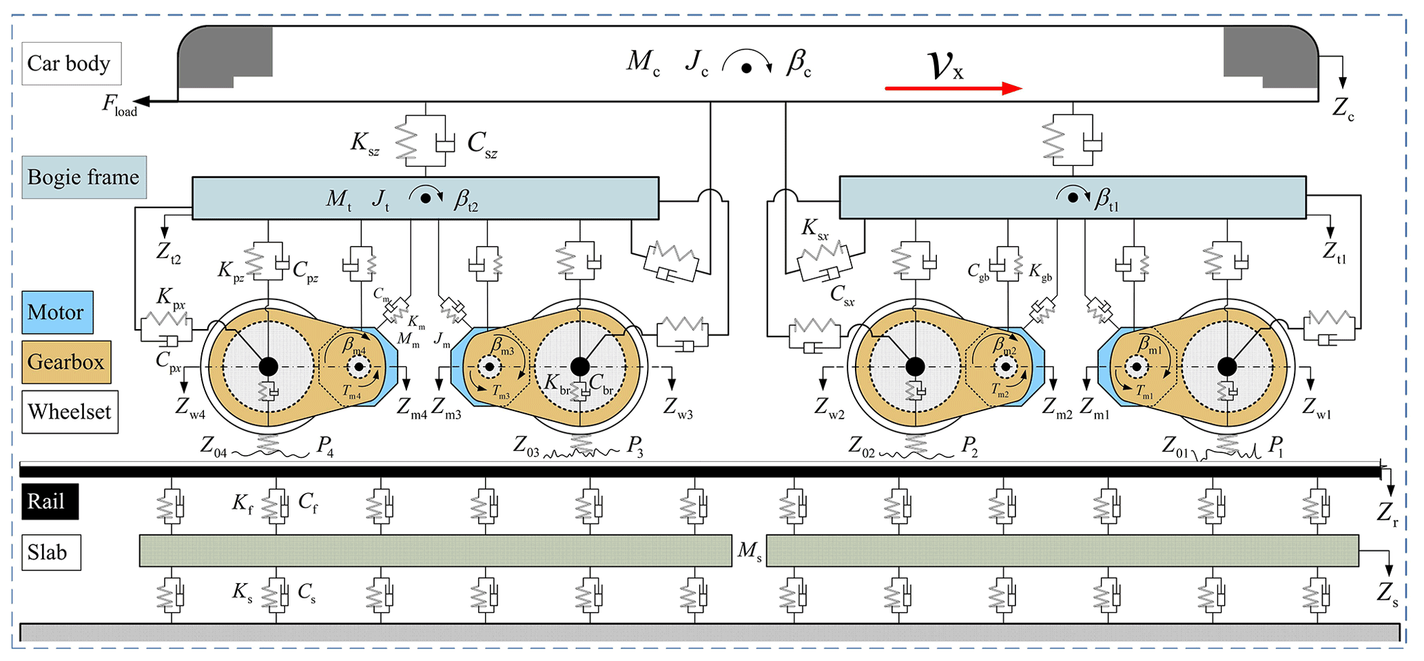
Figure 1Vehicle–track coupled dynamics model of a metro vehicle with traction motors and gear transmissions.
As a typical type of non-ballasted track structure, composed of rails, rail pads, and slabs, the slab track has been widely used in China because of its advantages of high stability, less maintenance, and long service life. Thus, the track subsystem in this vehicle–track coupled dynamics model of the metro vehicle is modeled as a slab-track structure, as shown in Fig. 1. The rails that bear the enormous pressure from the wheelsets are modeled as continuous Bernoulli–Euler beams with vertical motion supported by slabs. The slabs are treated as a finite-length free beam supported on the viscoelastic foundation which can be viewed as a continuous linear spring-damping. Since the equations of motion of the slab-track subsystem, which are solved by the modal superposition method, are well recorded in Zhai et al. (2009), they are not presented here.
2.1 Interaction forces between the traction transmission components
The traction transmission system of a metro vehicle is shown in Fig. 2a. The traction motor is frame-hung, and its rotor and the pinion of the gearbox are connected by a coupling. One end of the gearbox is connected to the bogie frame through the steeve, and the other end is connected to the wheelset. Therefore, the longitudinal degree of freedom between the gearbox and the bogie frame is not directly constrained. In this dynamics model, the spring-damper elements are adopted to concatenate the different rigid components of the metro vehicle. Since the calculation method of internal forces conducted by the secondary suspension system between the car body and the bogie frames, as well as the method conducted by the primary suspension system between the bogie frames and the wheelsets, are well documented in Chen et al. (2017b, c), only the forces between the other components are listed here.
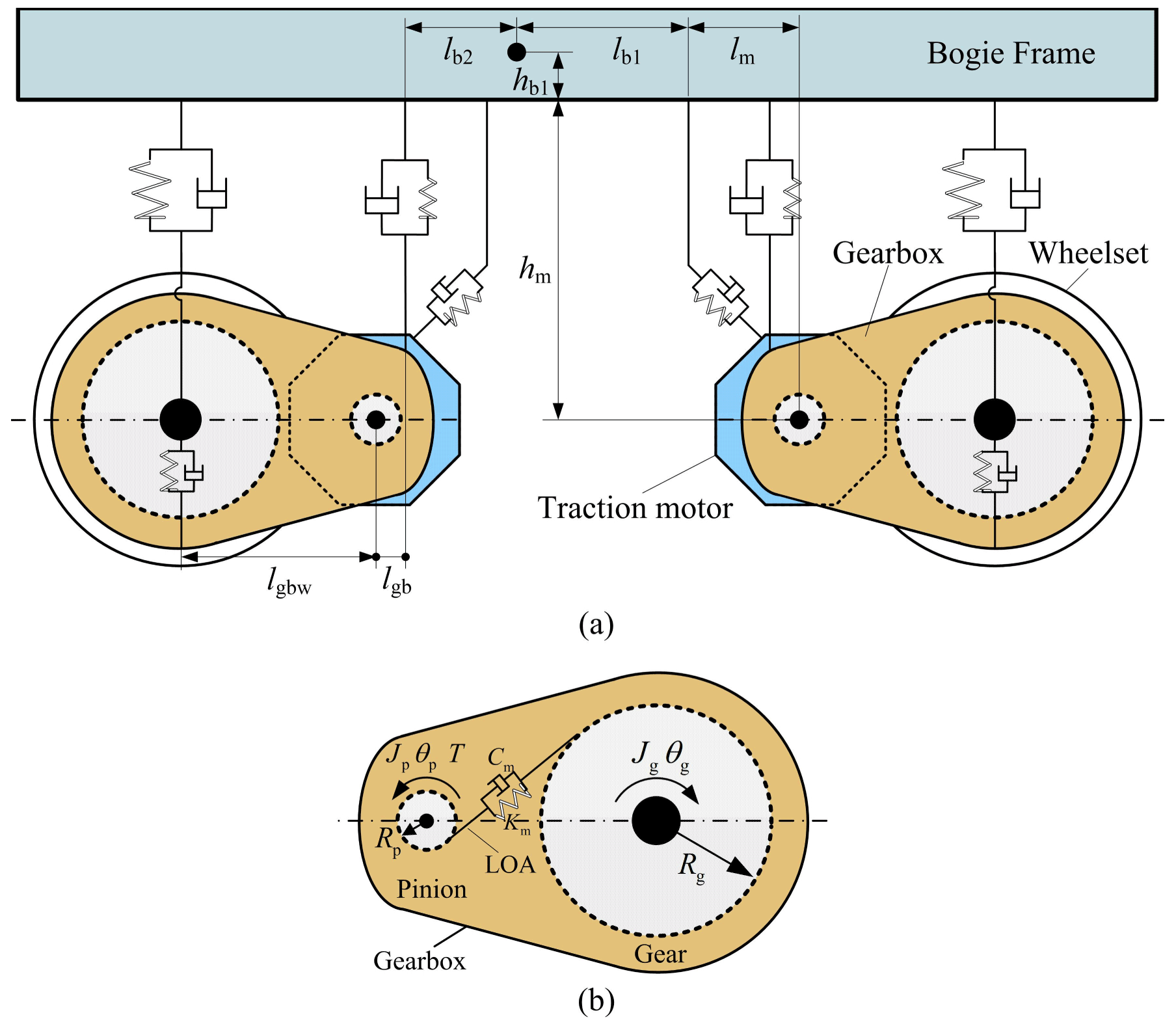
Figure 2Traction and transmission system of a metro vehicle. Schematic representation of (a) the drive system and (b) the gearbox and transmission subsystem.
The interaction forces between the bogie frames and the traction motors can be derived as
The interaction forces between the gearboxes and the traction motors can be calculated by
Similarly, the frame-gearbox acting forces carried by the gearbox steeve can be calculated by
The interaction forces between the gearbox and the wheelset are derived as
Through the gear teeth engagement, the forces and motions from the traction motors can be transmitted to the wheelsets. As shown in Fig. 2b, the mesh force along the line of action (LOA) between the pinion and the gear can be calculated as
where Kpg and Cpg are the gear mesh stiffness and the damping, respectively. The dynamic transmission error (DTE) is represented by δ, and the dot above the δ means the first-order differential.
In this paper, the time-varying mesh stiffness (Kpg) is calculated by the analytical model established by Chen et al. (2020) based on the potential energy principle, and it can be expressed as Eq. (6) where the notations of it have been explained in their works:
where the single-tooth mesh stiffness Ki can be described as
where the symbols Ka, Kb, Kss, Kff, Kh denote the bending stiffness, shear stiffness, axial compressive stiffness, tooth fillet-foundation deformation, and contact deformation of the tooth pair, respectively, and the subscripts p and g denote the pinion and the gear, respectively.
The DTE can be derived as
where the subscripts i = p, g point to the pinion and gear, respectively. The base circle radius of the gears and their rotational displacements are denoted as Ri and θi, respectively. The symbols Zgbk, Zwk, Xgbk, and Xwk (k = 1–4) represent the vertical and longitudinal displacements of the gearbox and the wheelset, and the wheelset number k=1 represents the front-most position on the direction of metro vehicle operation. The gear error ei may include the assembly and the manufacturing errors.
2.2 Nonlinear wheel–rail contact force
To calculate the wheel–rail contact force, the nonlinear Hertz elastic contact theory is used to calculate the vertical contact force on the wheel–rail interface, and the calculation formula is denoted as (Zhai and Sun, 1994; Zhai, 2020)
where G is the Hertz wheel–rail contact constant, for the worn profile tread used in the metro vehicle, m N, where R0 is the wheel radius. The elastic compressive deformation of the wheel–rail contact is denoted as δZ(t) and can be calculated as
where Zw and Zr denote the vertical displacements of the wheelset and the rail at the wheel–rail contact point. The Z0(t) denotes the geometrical irregularities on the surface of the wheel and rail, such as track irregularities, rail corrugation, wheel polygonization, etc.
When the metro vehicle operates under the action of the drive torques transmitted from the traction motors, the wheels will creep against the rails to generate the creep forces. The creep force is the link between the metro vehicle's longitudinal movement and the motor–gearbox transmission subsystem. It is also an important factor for studying the dynamic interaction between the wheelsets and the rails which can be given as
where μ is the adhesion coefficient of the wheel–rail contact interface, which is determined by complicated factors. The formula for calculating the adhesion coefficient can refer to Chen et al. (2017b).
2.3 Dynamic equation of the motor–gearbox transmission components
Combining Figs. 1 and 2, based on the D'Alembert's principle, the corresponding dynamic equations of motion of the motor–gearbox transmission system are derived as follows:
Pitch, bounce, and longitudinal motions of traction motors
Pitch, bounce, and longitudinal motions of gearboxes
Pitch, bounce, and longitudinal motions of the wheelsets
Rotational motion of the rotor
Rotational motion of the pinion
Rotational motion of the gear
In Eqs. (12)–(17), the symbols Ji and θi denote the moment of inertia and the rotational displacement (the subscript i = t for bogie frame, m for traction motor, r for rotor, p for pinion, g for gear, gb for gearbox, and w for wheelset). The Rp, Rg, and R0 are the base circle radius of the pinion, gear, and wheel radius, respectively. The Tm, Trp, and Tgw are the output torque of the traction motor, the torque transmitted between the rotor and the pinion, and the torque transmitted between the gear and wheelset, respectively. The wheel–rail creep force is Fcreep.
In order to improve the calculation efficiency for the whole dynamics model of metro vehicles with large-scale degrees of freedom (DOFs) and multiple nonlinear links, Zhai's integration algorithm is adopted here for the numerical solution (Zhai, 1996).
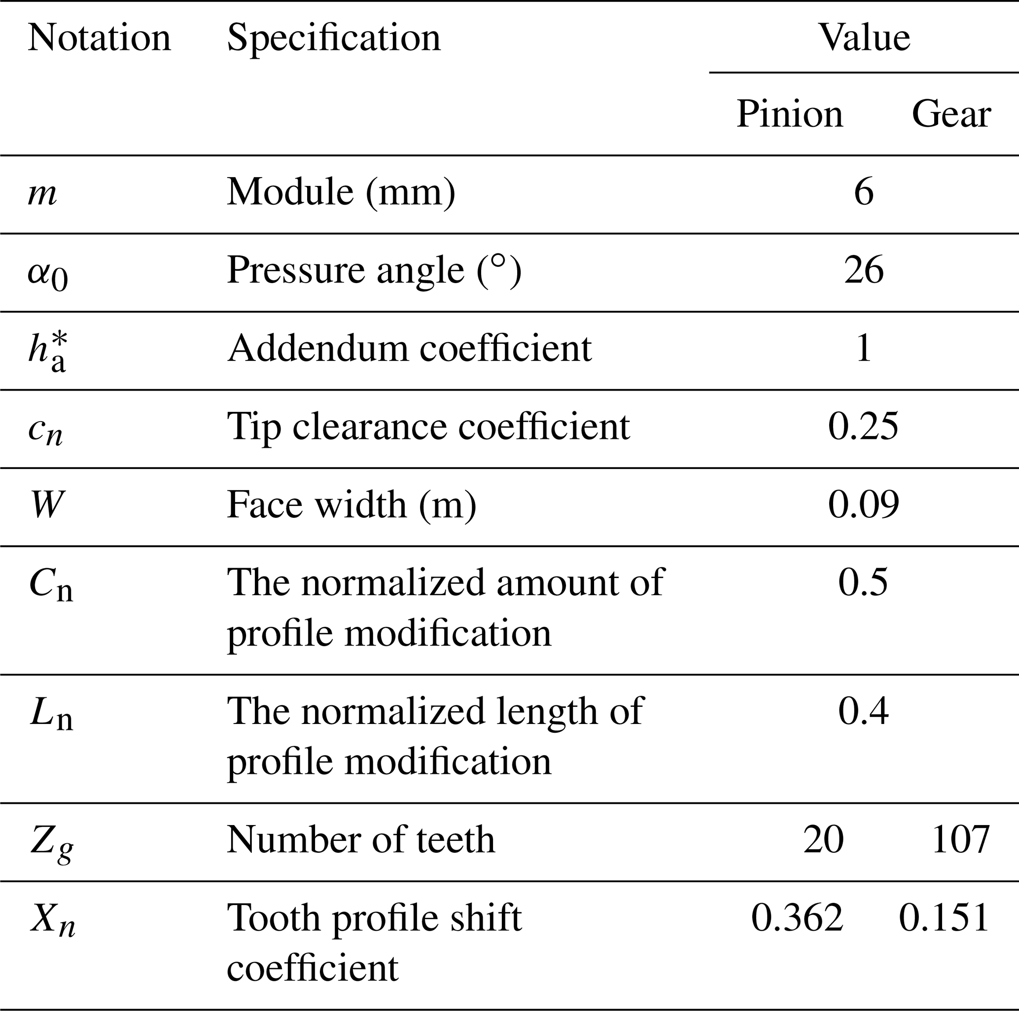
Owing to the fact that the gear is not as stable as the ideal involute gear in practical operation, the dynamic load caused by the meshing impact affects the bearing capacity. Tooth profile modification (TPM) is a means to reduce the impact vibration and noise, weaken the dynamic load, improve the lubrication state of the tooth surface, and in turn, slow down or prevent the gear scuffing. The TPM of both gear and pinion in this dynamics model is applied at the tooth tips because modifying the root or tip of one gear has the same effect (Lin et al., 1994). According to the relevant standards mentioned in Chen and Shao (2013) and the standard tip relief limitations (Li and Mao, 2008), the normalized amount and length of TPM for gear and pinion are set as 0.5 and 0.4, respectively. Based on the main parameters of the gear pair used in the metro vehicle dynamics model, as shown in Table 1, the time-varying mesh stiffness with TPM can be calculated through Eq. (6).
The traction characteristic curve of the metro vehicle without load (AW0) is shown in Fig. 3. To avoid applying too much traction force at the beginning of the simulation, the traction force can be set to increase linearly with the running speed less than 2 km h−1 in the simulation process. Due to the good condition of the new track, the Association of American Railroads class 6 irregularity is adopted in all simulation processes. The main design parameters of the metro vehicle and slab-track structure are given in Tables 2 and 3.
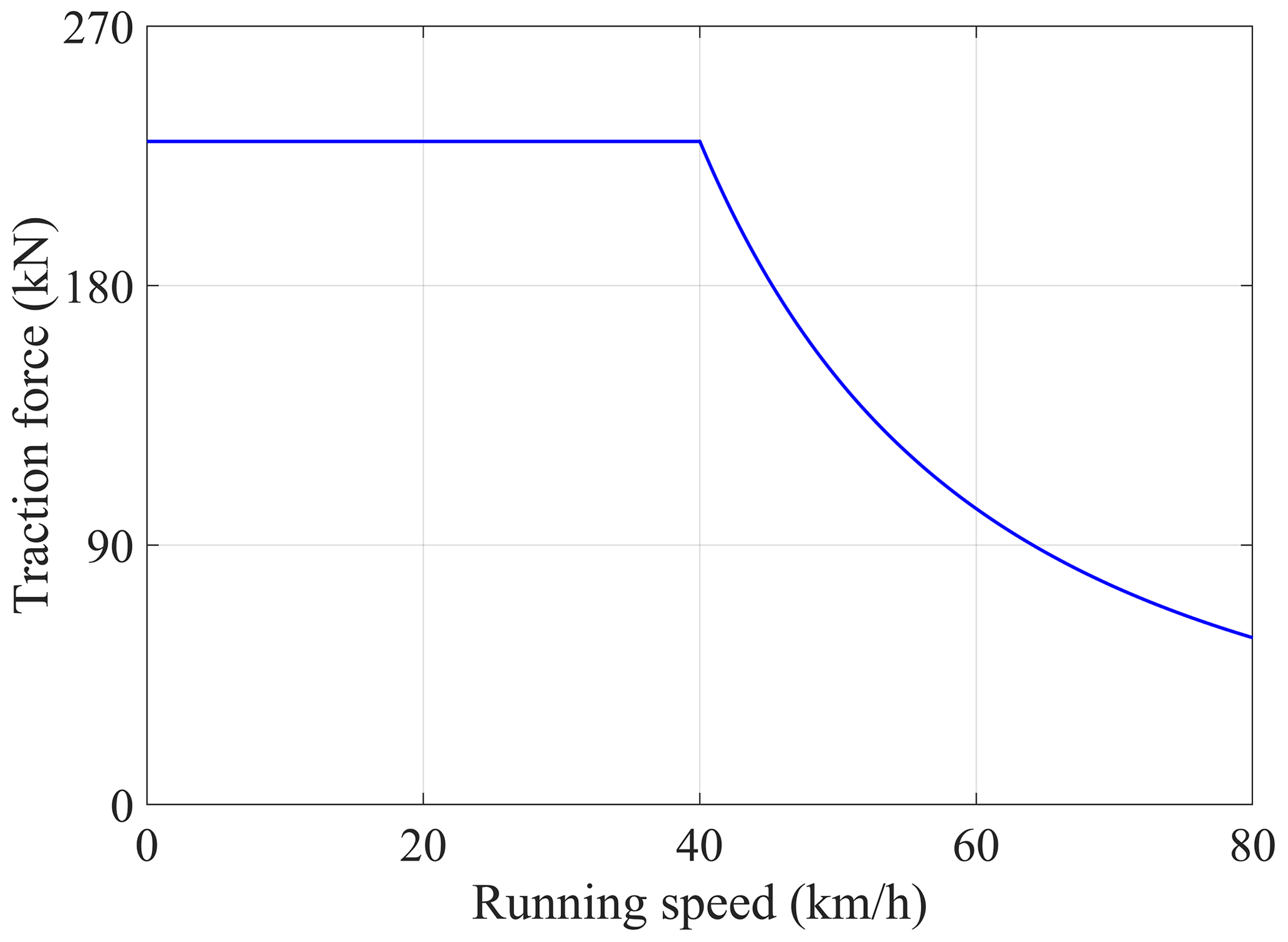
Table 1Main parameters of the gear pair of the transmission system.

3.1 Model validation
Based on the established coupled dynamics model, simulation analysis of the metro vehicle can be done under traction conditions.
The field test was carried out on the straight line of a Qingdao Metro Line in China. Prior to the test, accelerometer sensors were installed on the car body, bogie frame, traction motor, and axle box according to the relevant test standards, and the positions and testing photograph are shown in Fig. 4. Then, the vibration responses of the metro major components can be collected in traction conditions. According to the vibration responses acquired from the field tests in the first 7 s of the speed-up process, the same situation of the numerical simulations as field tests are also performed in the developed vehicle–track coupled dynamics model.
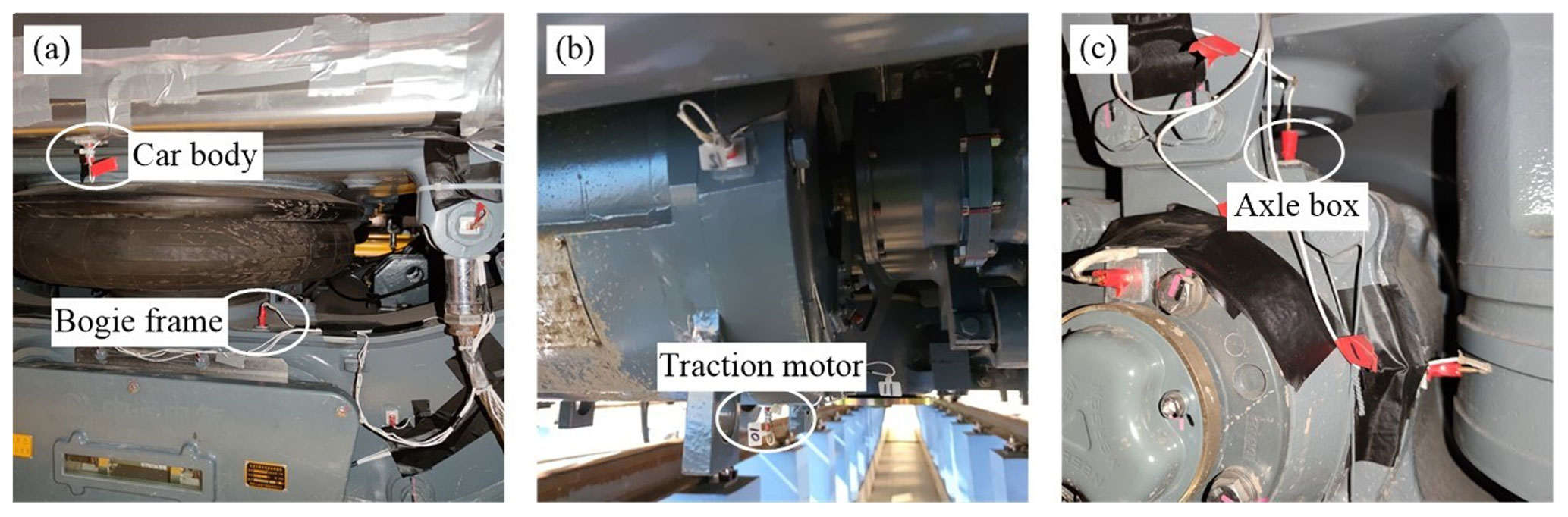
Figure 4Accelerometer sensors on (a) the car body and bogie frame, (b) traction motor, and (c) axle box.
3.1.1 Model validation in the time domain
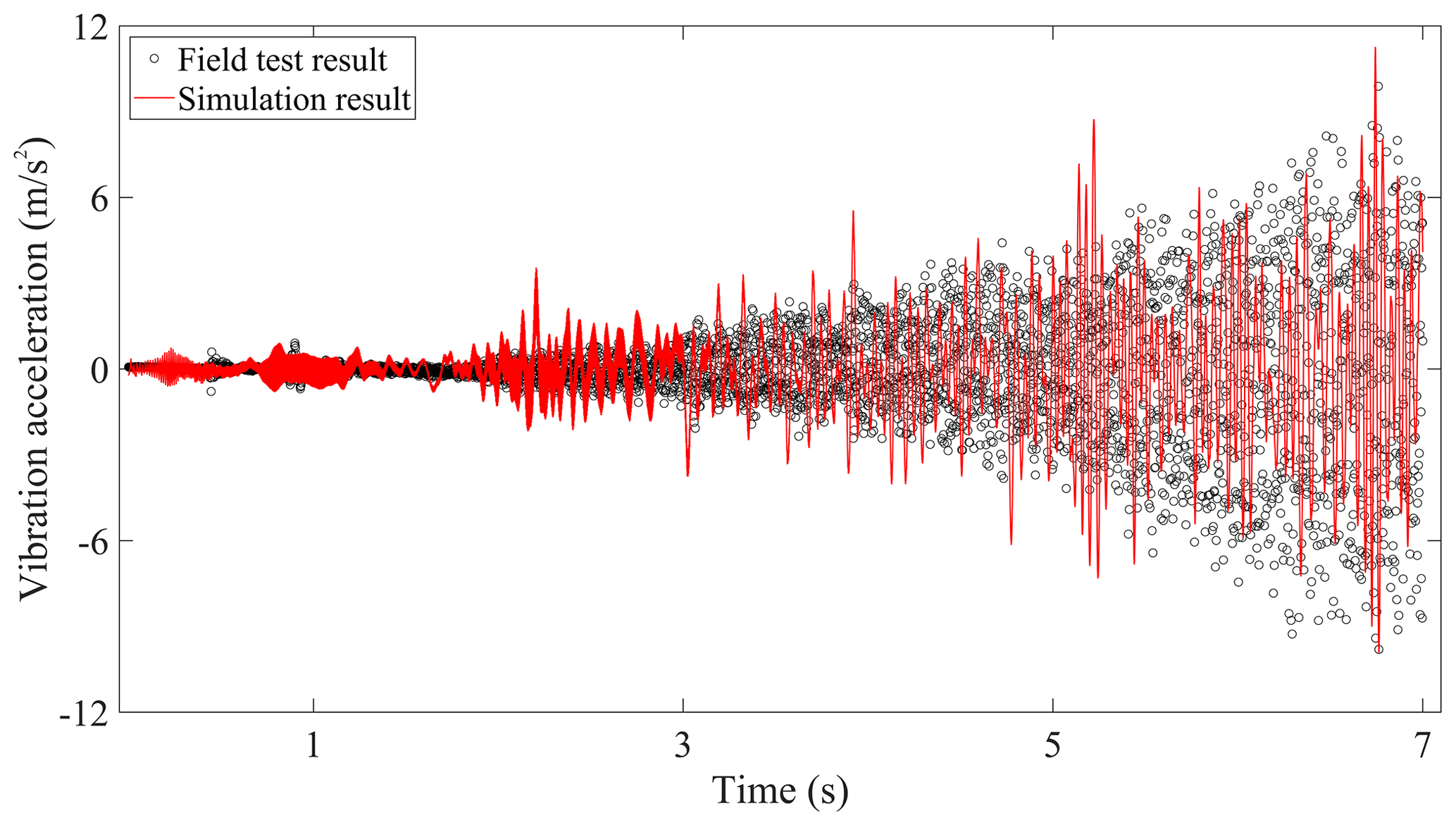
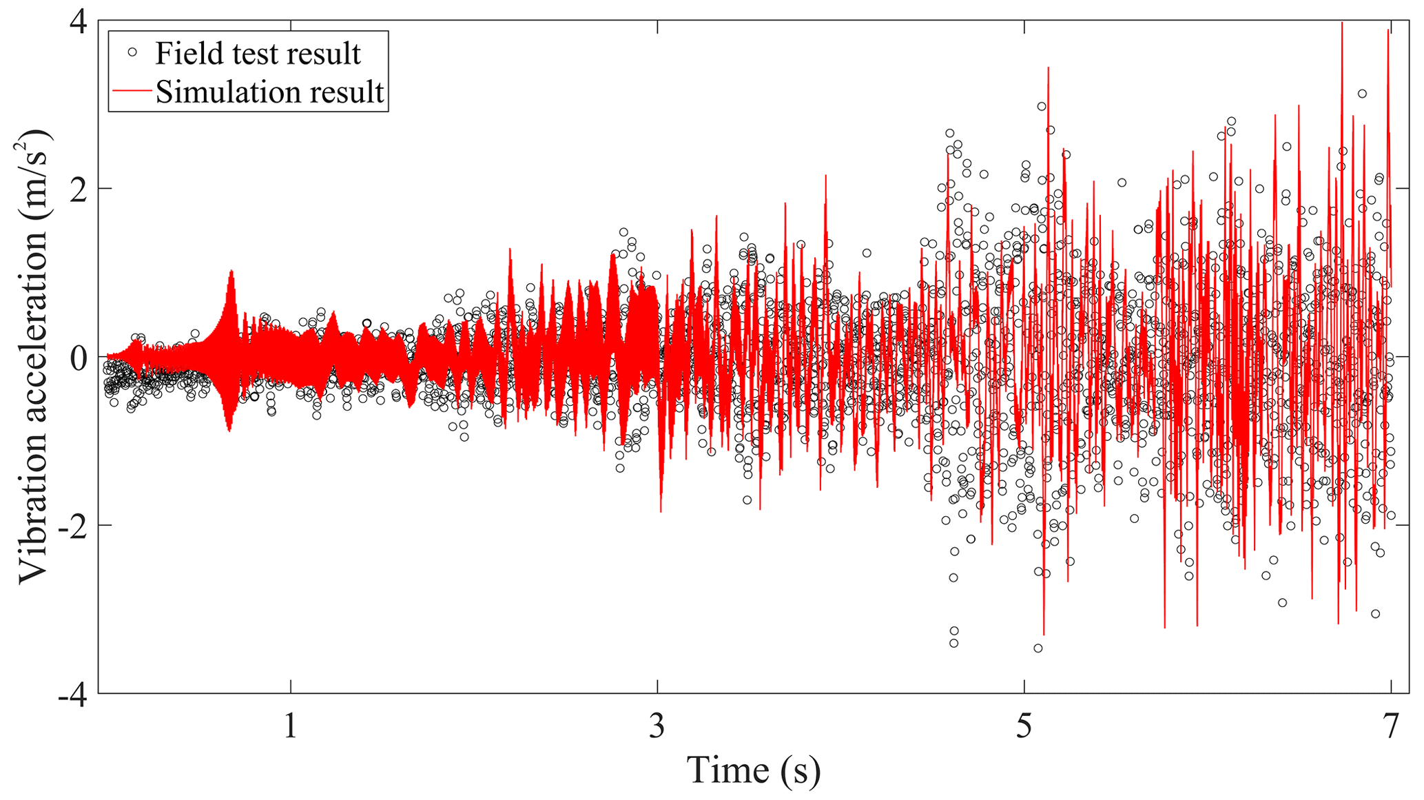
The comparisons of the vertical vibration responses in time histories on car body, bogie frame, traction motor, and wheelset between the field test results and simulation results are displayed in Figs. 5–8, respectively. Due to the dynamic interaction of the wheel–rail under track irregularity, the self-excited vibration of the driving system under the traction torque, and the gear mesh force that gradually intensifies with the speed-up process, it can be seen that the vibration intensity of these tested components increases gradually, and the same trend also occurs in the simulation results.
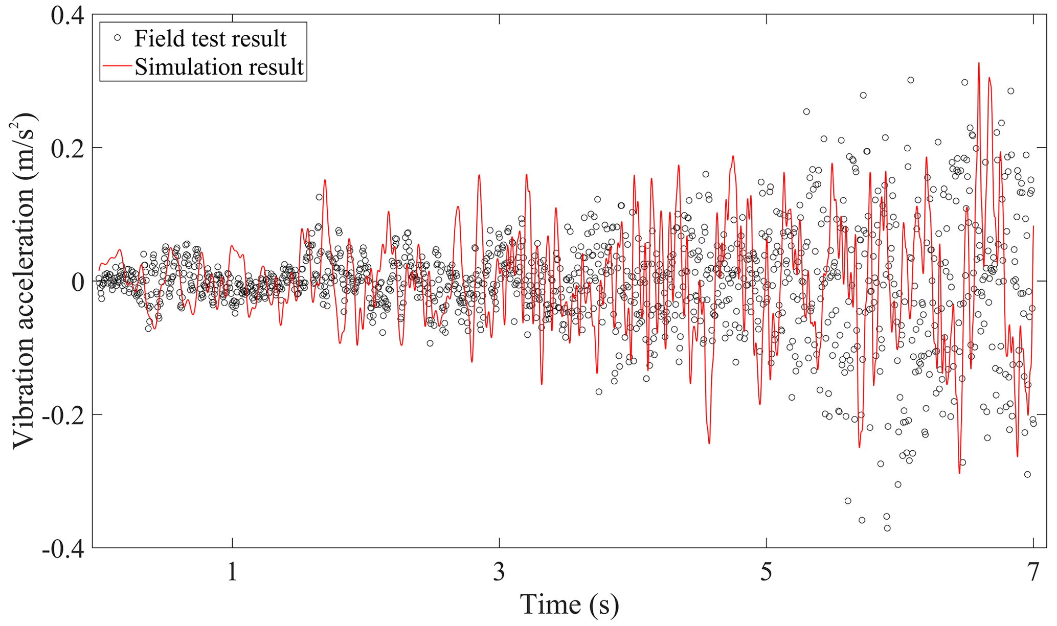
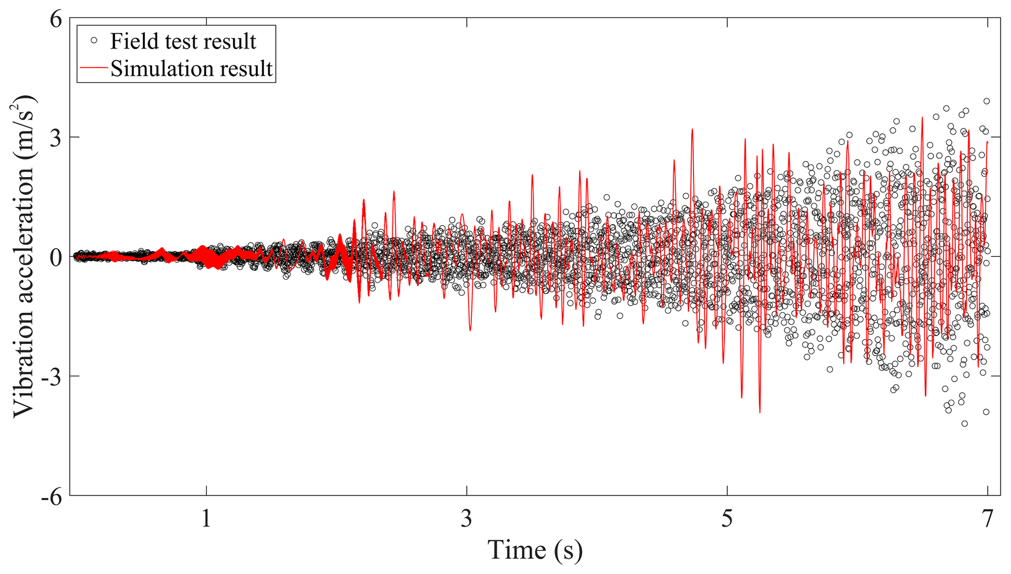
Figure 5 compares the simulation results and field test vibration accelerations of the car body. The amplitude of vibration acceleration is relatively small, which is consistent with the high comfort requirements of the metro vehicle. Since the car body is regarded as rigid, the local flexible vibration of the car floor around the accelerometer sensor could not be revealed in the simulated results, so the field test results of the car body have much more high-frequency components than the simulation results. Furthermore, it should be noted that the vibration accelerations of the traction motor in Fig. 7 are generally greater than that of the bogie frame and the wheelset in Figs. 6 and 8 in amplitude, and the vibration amplitude of the bogie frame and wheelset is equivalent. The main reason is that the metro vehicle requires a fast start, which needs to reach high running speeds in a short time. The rotor rotates relative to the stator, and the huge traction torque causes the vibration of the driving system to intensify. However, the stator of the traction motor is fixedly connected to the bogie frame, namely the traction motor is frame-hung, so the vibration of the traction motor will seriously affect that of the bogie frame. Therefore, in the initial stage of metro vehicle speed-up, the vibration characteristics of the metro components are different from those of heavy-haul locomotive, which has the vibration decaying law during the down–up transmission of wheelset–motor–bogie frame–car body introduced in Chen et al. (2017c). Meanwhile, it just shows that the effect of the gear transmission systems on the vibration of the bogie frames in metro vehicles is more obvious than that of the locomotive, so it is necessary to carry out the coupling vibration study of the gear transmission system and the bogie frame in the future research.
In all, the simulation results are basically consistent with the field test data in the variation tendency and amplitude of vibration acceleration, which can verify the accuracy of the established vehicle–track coupled dynamics model.
3.1.2 Model validation in the time–frequency distribution
To further validate the established dynamics model, comparisons of the vibration responses in time–frequency distribution between the simulation results and the field test results have been made in this subsection. Although the previous papers (Chen et al., 2017c; Zhang et al., 2019a) verify that the excitations from the gearbox, mainly the gear mesh, can hardly affect the vibration responses of the car body and the bogie frame in the locomotive, considering the difference that the gearboxes of the metro vehicle are suspended on the bogie frames, the traction motors, wheelsets, and bogie frames are closely connected to the gear transmission systems. By using the short-time Fourier transform (STFT), the comparisons of vertical vibration responses in the time–frequency distribution of them are represented in Figs. 9–11, respectively. It can be seen that the gear mesh frequency and its harmonics are clearly visible, and their values and amplitudes increase with the vehicle running speed, both in the simulation results and the field test results, which coincide with the time-domain variation law introduced in Sect. 3.1.1. Due to the more complicated and unpredictable excitations from the wheel–rail contact interface, the frequency components of the field test results are much more complex than the simulation results.
The traction motor and wheelset are directly affected by the gear meshing. Figures 9 and 10 illustrate the time–frequency distributions of the vertical vibration responses of the traction motor and the wheelset. Compared to the vibration of the wheelset in the field test results, the gear mesh frequency and its harmonics of the traction motor vibration responses are more obvious under the whole speed-up process, especially at a higher speed. The main reason is that the wheelset is excited not only by the gear meshing, but also by the wheel–rail contact interface, which makes the periodic components submerged into the background noise to some extent. Similarly, a phenomenon similar to the time–frequency distribution of the traction motor can be seen in the vibration response of the bogie frame in Fig. 11. The difference is that the vibration amplitude of the wheelset and bogie frame is roughly the same, while the vibration amplitude of the traction motor is generally higher than that of both, which can also be seen from the time domain.
Consequently, the time–frequency distributions of the vibration responses of the key components by using the established vehicle–track coupled dynamics model are basically consistent with the field test results from the metro vehicle in terms of the main frequency components, amplitude, and variation trend. The accuracy of the established dynamics model is verified from the perspective of both time domain and time–frequency domain.
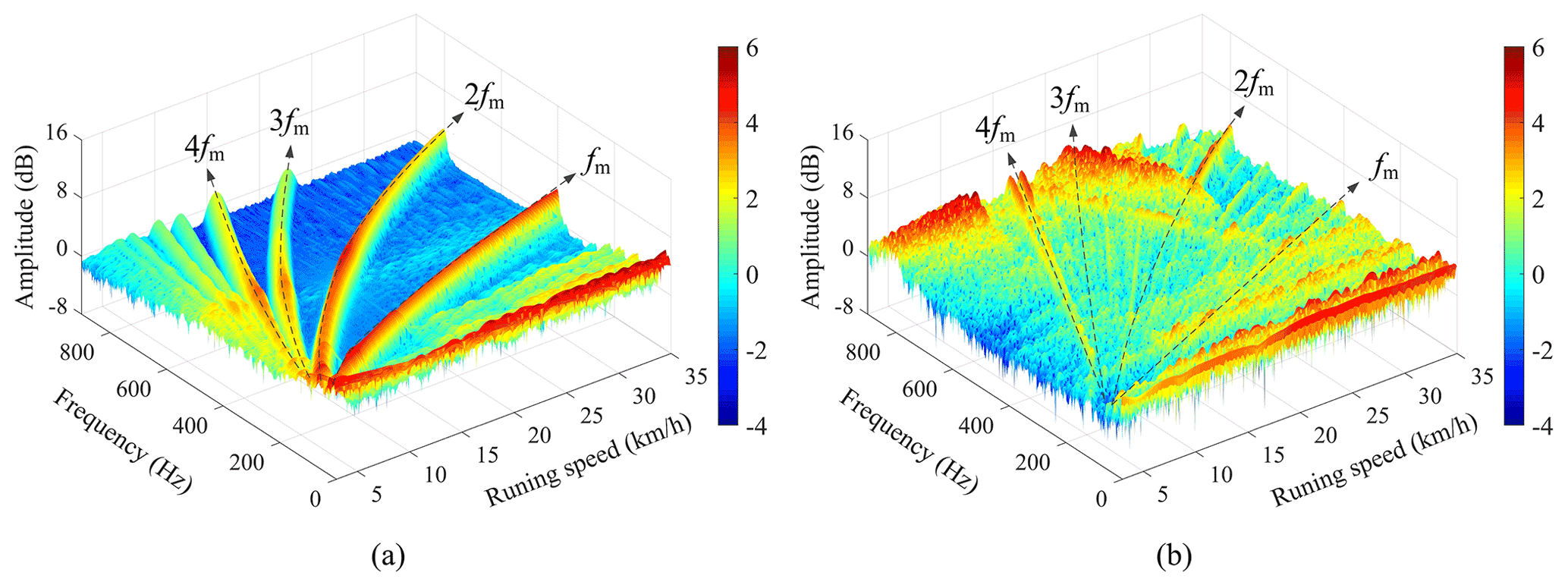
Figure 9Time–frequency distribution of the traction motor vibration responses: (a) simulated results, (b) field test results.
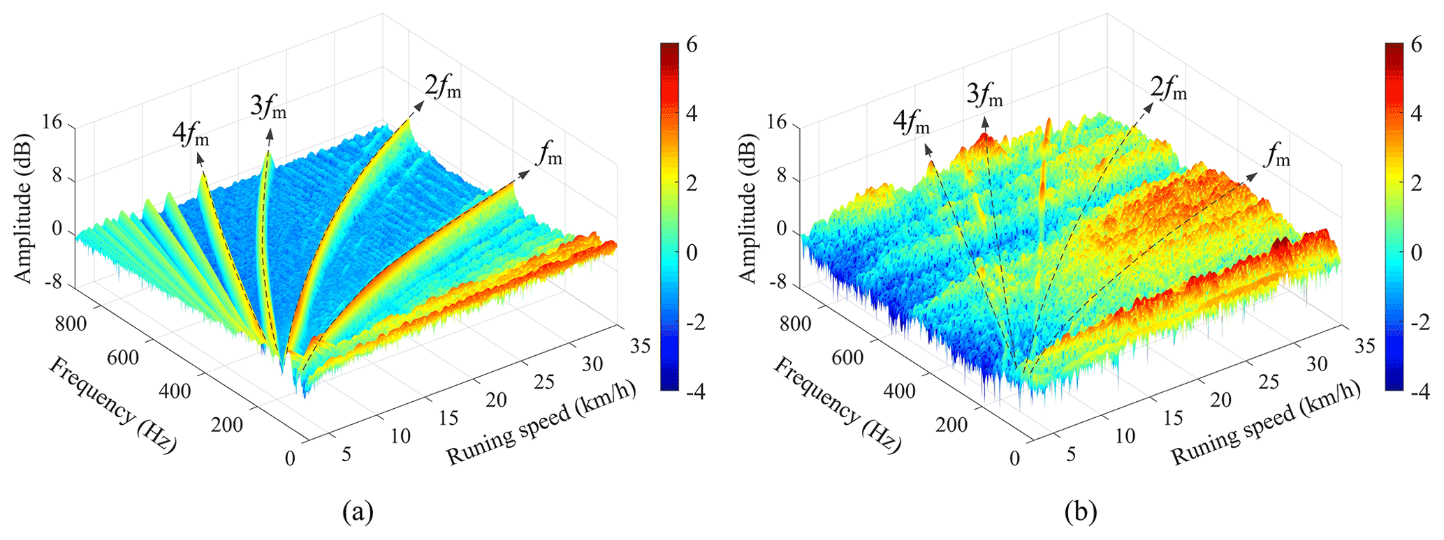
Figure 10Time–frequency distribution of the wheelset vibration responses: (a) simulated results, (b) field test results.
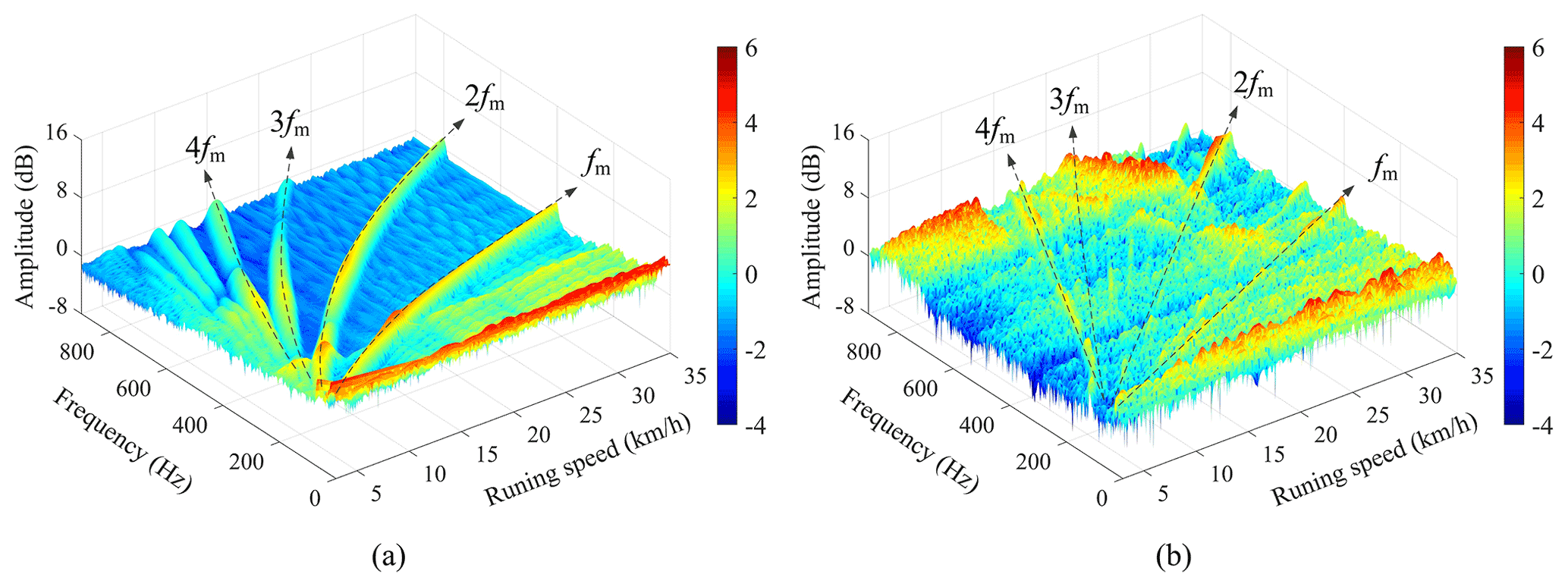
Figure 11Time–frequency distribution of the bogie frame vibration responses: (a) simulated results, (b) field test results.
3.2 Effect of the gear mesh force on the metro vehicle driving system
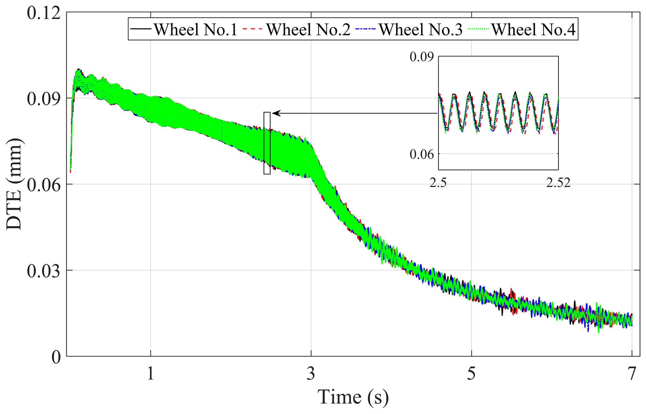
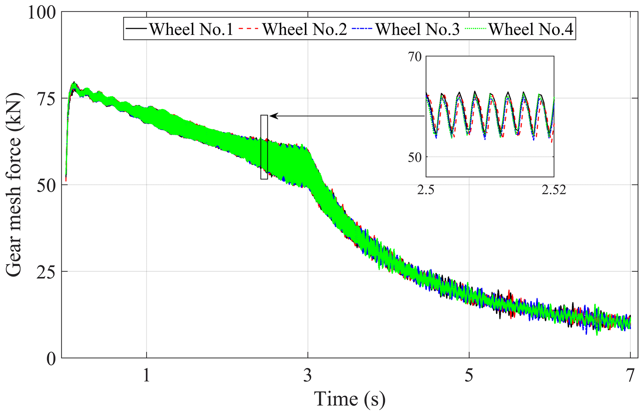
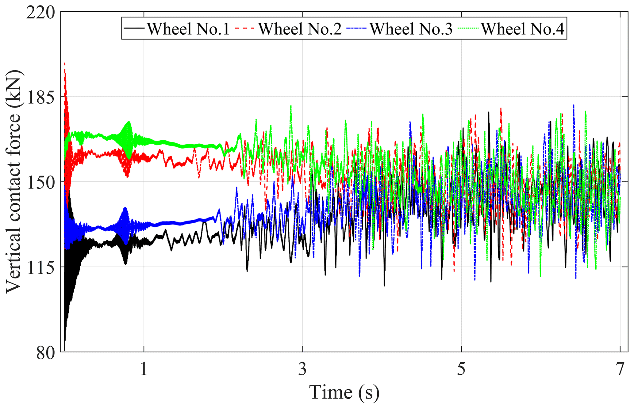
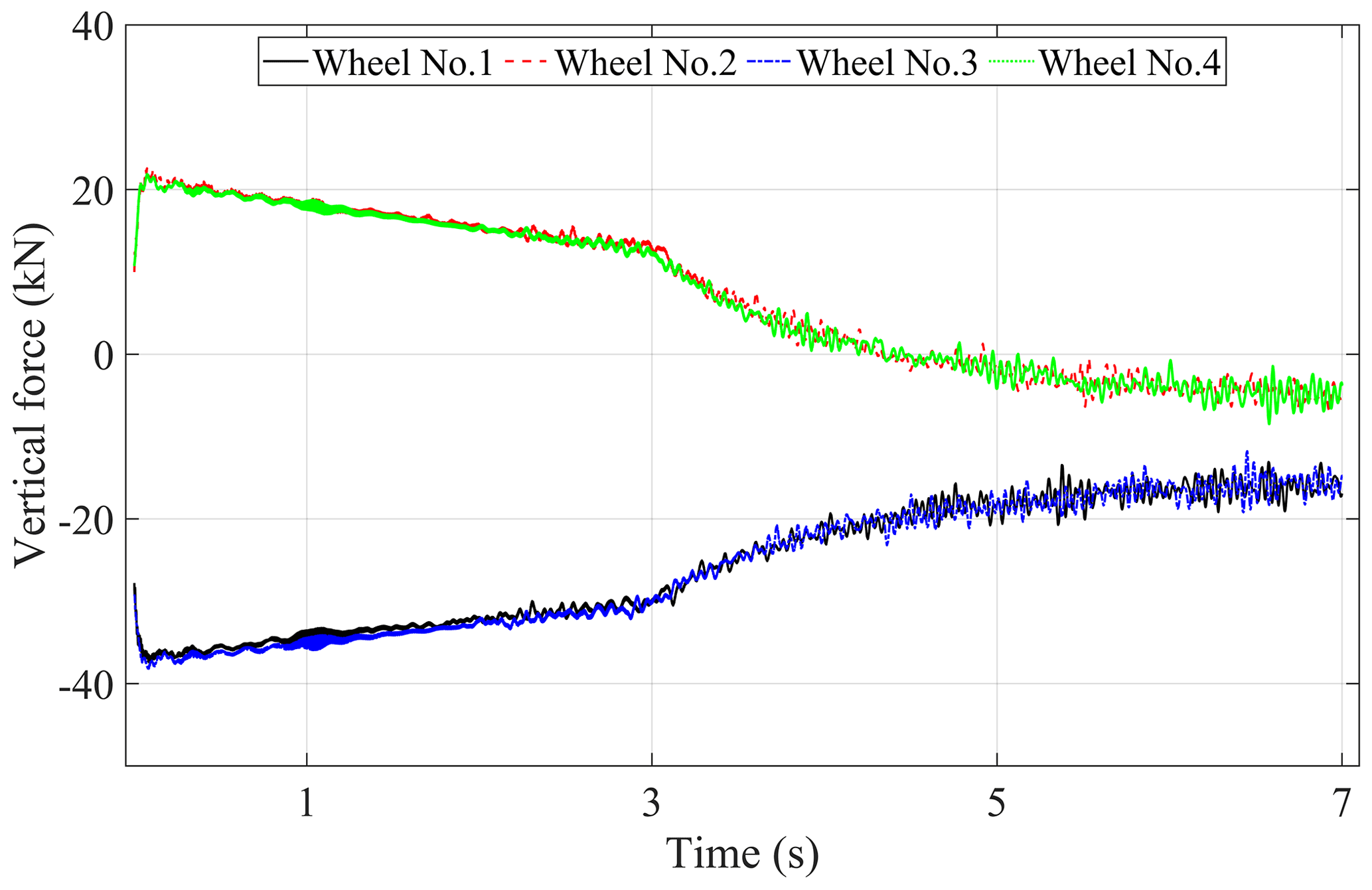
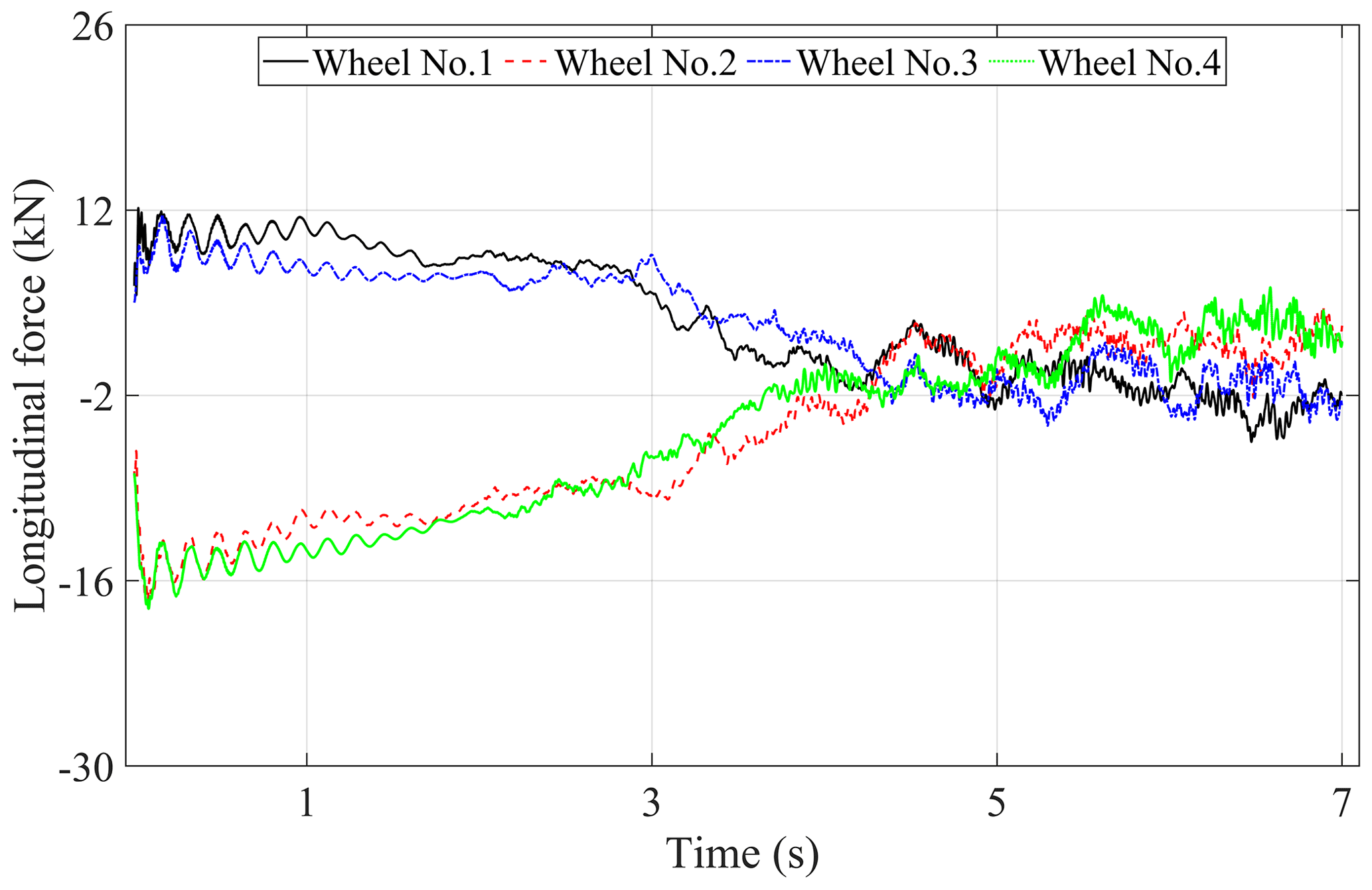
The gear dynamic mesh force is one of the main internal excitations of the driving system in the metro vehicle. Due to the frequent conversion of traction and braking conditions, the interaction between the components of the driveline will be more intense in the metro vehicle. To investigate the effect of the gear mesh forces on the dynamic responses of the metro vehicle driving system, some analysis has been done by using the time-varying mesh stiffness under traction conditions. The time histories of the DTEs, gear dynamic mesh forces, wheel–rail vertical contact forces, and the vertical and longitudinal interaction forces between the traction motors, gearboxes, and bogie frames are shown in Figs. 12–16, respectively. The legends of these figures (Wheel No. 1, Wheel No. 2, Wheel No. 3, Wheel No. 4) represent the relevant description in the corresponding position of the car body.
Figure 12 shows that the variation trend and value of DTEs of all gear pairs in the metro vehicle are basically the same in the process of acceleration. At the stage of low running speed with constant traction force, DTE tends to decrease linearly as time goes on. With the decrease of traction force, DTE decreases more obviously, indicating that the excitation from the gear transmission system gradually becomes weak at a higher running speed. It can be known that the gear dynamic mesh forces which are shown in Fig. 13 have similar variation law with the DTEs according to Eq. (6). Because there is an angle between the gear dynamic mesh force and the vertical–longitudinal direction which can be seen in Fig. 2b, and the opposite direction of the dynamic gear mesh force of the two gear pairs in the same bogie frame, the vertical component force of that in the opposite direction will produce the phenomenon of axle load transfer which can be seen in Fig. 14, and the detailed description can be found in Chen et al. (2018). It should be noted that the axle load transfer phenomenon becomes very weak because the static axle load is relatively large, which also supports the previous conclusion that the excitation of the gear transmission system becomes weak at a higher speed.
In addition, Figs. 15 and 16 show the effect of the gear mesh forces on the traction motors and gearboxes. In Fig. 15, due to the effect of gear dynamic mesh forces, it can be seen that the suspension steeves located in “Wheel No. 1” and “Wheel No. 3” between the gearboxes and bogie frames are subjected to the stretch forces, while that located in “Wheel No. 2” and “Wheel No. 4” suffer the compressive forces at the lower-speed stage, but all of that will be in the stretch state when the effect of gear mesh force is less than the effect of gearbox gravity, and the gear mesh forces will continue to affect the force state of gearboxes because of the small weight. The same phenomenon can also be seen in Fig. 16, but the difference is that the gear mesh forces have little effect on the longitudinal interaction forces between the traction motors and the bogie frames because the longitudinal component of the gear mesh force is relatively small due to the small gear mesh angle, especially at the high running speed, so the longitudinal forces of the traction motors tend toward a stable positive value because the metro vehicle is in the traction condition. Therefore, compared to the influence on the axle load transfer, the gear mesh force has a great and lasting effect on the traction motors and gearboxes.
According to the specific structure and the main parameters of the metro vehicle components, a vertical–longitudinal dynamics model which considers the frame-hung traction motor and gearbox is established in this paper. In particular, the vertical and longitudinal coupling effect of the gear transmission system is considered. Based on the established dynamics model, the corresponding vibration responses are extracted from the simulation with the effect of the gear time-varying mesh stiffness and the excitation from the track geometrical irregularity in traction. By comparing the simulation results and field test results in both time domain and time–frequency domain, the coupled model is validated to be reliable in the analysis of the metro vehicle dynamics characteristic. The analysis results indicate that the gear dynamic mesh force is the coupling link of the drive system in the vertical and longitudinal directions. Compared to the wheelset, the gear mesh force has a greater effect on the force state of the traction motor and gearbox. As a result, this dynamics model can be used to analyze the effect of the suspension stiffness and suspension position of the traction motor and gearbox on the dynamic characteristics of the metro vehicle, and in turn, it can help to optimize the suspension parameters of these components. Besides, further research works, such as the dynamic characteristics analysis of the traction motor–gearbox transmission system under the abnormal service conditions of the gear faults and wheel and rail defects, can be investigated.
| Notation | Specification |
| Mc | Car body mass |
| Mt | Bogie frame mass |
| Mw | Wheelset mass |
| Mm | Traction motor mass |
| Mgb | Gearbox mass |
| Jc | Mass moment of inertia of car body |
| Jt | Mass moment of inertia of bogie frame |
| Jw | Mass moment of inertia of wheelset |
| Jm | Mass moment of inertia of traction motor |
| Jgb | Mass moment of inertia of gearbox |
| Kpz | Stiffness of primary suspension |
| Ksz | Stiffness of secondary suspension |
| Kbmz | Vertical stiffness between traction motor and bogie frame |
| Kbmx | Longitudinal stiffness between traction motor and bogie frame |
| Kgbmz | Vertical stiffness between gearbox and traction motor |
| Kgbmx | Longitudinal stiffness between gearbox and traction motor |
| Kbgbz | Vertical stiffness between bogie frame and gearbox |
| Kgbwz | Vertical stiffness between gearbox and wheel axle |
| Kgbwx | Longitudinal stiffness between gearbox and wheel axle |
| Kpg | Gear mesh stiffness |
| Ki | Single-tooth mesh stiffness of the ith tooth pair |
| Ka | Bending stiffness |
| Kb | Shear stiffness |
| Kss | Axial compressive stiffness |
| Kff | Tooth fillet-foundation stiffness |
| Kh | Hertzian contact stiffness of gear teeth |
| Cpz | Damping coefficient of primary suspension |
| Csz | Damping coefficient of secondary suspension |
| Cbmz | Vertical damping coefficient of suspension connecting traction motor and bogie frame |
| Cbmx | Longitudinal damping coefficient of suspension connecting traction motor and bogie frame |
| Cgbmz | Vertical damping coefficient of suspension connecting gearbox and traction motor |
| Cgbmx | Longitudinal damping coefficient of suspension connecting gearbox and traction motor |
| Cbgbz | Vertical damping coefficient of suspension connecting bogie frame and gearbox |
| Cgbwz | Vertical damping coefficient of suspension connecting gearbox and wheel axle |
| Cgbwx | Longitudinal damping coefficient of suspension connecting gearbox and wheel axle |
| Cpg | Gear mesh damping coefficient |
| Lc | Semi-longitudinal distance between bogies |
| lt | Semi-longitudinal distance between wheelsets in bogie |
| Longitudinal/vertical distance between the center of the traction motor and its suspension point on the bogie frame | |
| Longitudinal/vertical distance between the center of the bogie frame and the suspension point of the traction motor on the bogie frame | |
| Longitudinal distance between the center of bogie frame/gearbox and the suspension point of the gearbox on the bogie frame | |
| lgbw | Distance between centers of pinion and gear |
| R0 | Wheel radius |
| m | Module |
| α0 | Pressure angle |
| Addendum coefficient | |
| cn | Tip clearance coefficient |
| W | Face width |
| Cn | The normalized amount of profile modification |
| Ln | The normalized length of profile modification |
| Zg | Number of teeth |
| Xn | Tooth profile shift coefficient |
| δ | Dynamic transmission error |
| Tm | The output torque of traction motor |
| Trp | The torque transmitted between the rotor and the pinion |
| Tgw | The torque transmitted between the gear and wheelset |
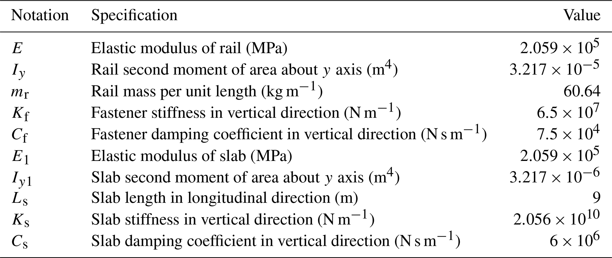
| E | Elastic modulus of rail |
| Iy | Rail second moment of area about y axis |
| mr | Rail mass per unit length |
| Kf | Fastener stiffness in vertical direction |
| Cf | Fastener damping coefficient in vertical direction |
| E1 | Elastic modulus of slab |
| Iy1 | Slab second moment of area about y axis |
| Ls | Slab length in longitudinal direction |
| Ks | Slab stiffness in vertical direction |
| Cs | Slab damping coefficient in vertical direction |
| Z | Vertical displacement |
| Longitudinal displacement | |
| Rotation angle | |
| P(t) | Vertical contact force on the wheel–rail interface |
| G | Hertz wheel–rail contact constant |
| δZ(t) | Elastic compressive deformation of the wheel–rail contact |
| μ | Adhesion coefficient of the wheel–rail contact interface |
| Subscript | |
| c | Car body |
| t | Bogie frame |
| w | Wheelset |
| gb | Gearbox |
| p | Pinion |
| g | Gear |
| m | Traction motor |
| f | Fastener |
| s | Slab |
| z | Vertical direction |
| x | Longitudinal direction |
All raw data can be provided by the corresponding authors upon request.
ZC and KW planned the research work; TZ and TJ performed the measurements; TZ and TJ analyzed the data; TZ and ZZ wrote the manuscript draft; and ZC and KW reviewed and edited the manuscript.
The contact author has declared that none of the authors has any competing interests.
Publisher’s note: Copernicus Publications remains neutral with regard to jurisdictional claims in published maps and institutional affiliations.
The authors would like to thank the National Natural Science Foundation of China for supporting this research. We also greatly appreciate the efforts of the reviewers and our colleagues.
This work was supported by the National Natural Science Foundation of China (grant nos. 52022083, 51775453, 51735012).
This paper was edited by Guangbo Hao and Davood Younesian, and reviewed by three anonymous referees.
Bahk, C. J. and Parker, R. G.: Analytical investigation of tooth profile modification effects on planetary gear dynamics, Mech. Mach. Theory, 70, 298–319, https://doi.org/10.1016/j.mechmachtheory.2013.07.018, 2013.
Brethee, K. F., Zhen, D., Gu, F. S., and Ball, A. D.: Helical gear wear monitoring: modelling and experimental validation, Mech. Mach. Theory, 117, 210–229, https://doi.org/10.1016/j.mechmachtheory.2017.07.012, 2017.
Chen, K. K., Huangfu, Y. F., Ma, H., Xu, Z. T., Li, X., and Wen, B. C.: Calculation of mesh stiffness of spur gears considering complex foundation types and crack propagation paths, Mech. Syst. Signal Pr., 130, 273–292, https://doi.org/10.1016/j.ymssp.2019.05.014, 2019.
Chen, S. Y., Tang, J. Y., and Wu, L. J.: Dynamics analysis of a crowned gear transmission system with impact damping: based on experimental transmission error, Mech. Mach. Theory, 74, 354–369, https://doi.org/10.1016/j.mechmachtheory.2014.01.003, 2014.
Chen, Z. G. and Shao, Y. M.: Mesh stiffness calculation of a spur gear pair with tooth profile modification and tooth root crack, Mech. Mach. Theory, 62, 63–74, https://doi.org/10.1016/j.mechmachtheory.2012.10.012, 2013.
Chen, Z. G., Zhang, J., Zhai, W. M., Wang, Y. W., and Liu, J. X.: Improved analytical methods for calculation of gear tooth fillet-foundation stiffness with tooth root crack, Eng. Fail. Anal., 82, 72–81, https://doi.org/10.1016/j.engfailanal.2017.08.028, 2017a.
Chen, Z. G., Zhai, W. M., and Wang, K. Y.: A locomotive–track coupled vertical dynamics model with gear transmissions, Vehicle Syst. Dyn., 55, 244–267, https://doi.org/10.1080/00423114.2016.1254260, 2017b.
Chen, Z. G., Zhai, W. M., and Wang, K. Y.: Dynamic investigation of a locomotive with effect of gear transmissions under tractive conditions, J. Sound Vib., 408, 220–233, https://doi.org/10.1016/j.jsv.2017.07.017, 2017c.
Chen, Z. G., Zhai, W. M., and Wang, K. Y.: Locomotive dynamic performance under traction/braking conditions considering effect of gear transmission, Vehicle Syst. Dyn., 56, 1097–1117, https://doi.org/10.1080/00423114.2017.1406609, 2018.
Chen, Z. G., Zhou, Z. W., Zhai, W. M., and Wang, K. Y.: Improved mesh stiffness calculation model of spur gear pair with tooth profile deviations, Mech. Mach. Theory, 149, 103838, https://doi.org/10.1016/j.mechmachtheory.2020.103838, 2020.
Choy, F. K., Polyshchuk, V ., Zakrajsek, J. J., Handschuh, R. F., and Townsend, D. P.: Analysis of the effects of surface pitting and wear on the vibration of a gear transmission system, in: Proceedings of International Tribology Conference (AUSTRIB 94), Elsevier, Perth, Australia, https://doi.org/10.1016/0301-679X(95)00037-5, 1994.
Gu, X. and Velex, P.: On the dynamic simulation of eccentricity errors in planetary gears, Mech. Mach. Theory, 61, 14–29, https://doi.org/10.1016/j.mechmachtheory.2012.10.003, 2013.
Huang, G. H., Zhou, N., and Zhang, W. H.: Effect of internal dynamic excitation of the traction system on the dynamic behavior of a high-speed train, P. I. Mech. Eng. F-J. Rai., 230, 1899–1907, https://doi.org/10.1177/0954409715617787, 2016.
Jiang, J. Z., Chen, Z. G., Zhai, W. M., Zhang, T., and Li, Y. F.: Vibration characteristics of railway locomotive induced by gear tooth root crack fault under transient conditions, Eng. Fail. Anal., 108, 104285, https://doi.org/10.1016/j.engfailanal.2019.104285, 2020.
Li, Z. and Mao, K.: The tooth profile modification in gear manufacture, Appl. Mech. Mater., 10–12, 317–321, https://doi.org/10.4028/www.scientific.net/AMM.10-12.317, 2008.
Lin, H. H., Oswald, F. B., and Townsend, D. P.: Dynamic loading of spur gears with linear or parabolic tooth profile modifications, Mech. Mach. Theory, 29, 1115–1129, https://doi.org/10.1016/0094-114X(94)90003-5, 1994.
Liu, Y. Q., Chen, Z. G., Zhai, W. M., and Wang, K. Y.: Dynamic investigation of traction motor bearing in a locomotive under excitation from track random geometry irregularity, Int. J. Rail Transp., 10, 72–94, https://doi.org/10.1080/23248378.2020.1867658, 2021a.
Liu, Y. Q., Chen, Z. G., Wang, K. Y., and Zhai, W. M.: Dynamic modelling of traction motor bearings in locomotive-track spatially coupled dynamics system, Vehicle Syst. Dyn., https://doi.org/10.1080/00423114.2021.1918728, online first, 2021b.
Liu, Y. Q., Chen, Z. G., Li, W., and Wang, K. Y.: Dynamic analysis of traction motor in a locomotive considering surface waviness on races of a motor bearing, Railway Engineering Science, 29, 379–393, https://doi.org/10.1007/s40534-021-00246-x, 2021c.
Ma, H., Pang, X., Feng, R. J., Zeng, J., and Wen, B. C.: Improved time-varying mesh stiffness model of cracked spur gears, Eng. Fail. Anal., 55, 271–287, https://doi.org/10.1016/j.engfailanal.2015.06.007, 2015.
Marques, F., Magalhães, H., Pombo, J., Ambrósio, J., and Flores, P.: A three-dimensional approach for contact detection between realistic wheel and rail surfaces for improved railway dynamic analysis, Mech. Mach. Theory, 149, 103825, https://doi.org/10.1016/j.mechmachtheory.2020.103825, 2020.
Mohammed, O. D., Rantatalo, M., and Aidanpaeae, J. O.: Dynamic modelling of a one-stage spur gear system and vibration-based tooth crack detection analysis, Mech. Syst. Signal Pr., 54–55, 293–305, https://doi.org/10.1016/j.ymssp.2014.09.001, 2015.
Moradi, H. and Salarieh, H.: Analysis of nonlinear oscillations in spur gear pairs with approximated modelling of backlash nonlinearity, Mech. Mach. Theory, 51, 14–31, https://doi.org/10.1016/j.mechmachtheory.2011.12.005, 2012.
Ouyang, T. C., Huang, H. Z., Zhou, X. R., Pan, M. Z., Chen, N., and Lv, D. L.: A finite line contact tribo-dynamic model of a spur gear pair, Tribol. Int., 119, 753–765, https://doi.org/10.1016/j.triboint.2017.12.010, 2018.
Raghuwanshi, N. K. and Anand, P.: Experimental measurement of mesh stiffness by laser displacement sensor technique, Measurement, 128, 63–70, https://doi.org/10.1016/j.measurement.2018.06.035, 2018.
Tamminana, V. K., Kahraman, A., and Vijayakar, S.: A study of the relationship between the dynamic factor and the dynamic transmission error of spur gear pairs, J. Mech. Design, 129, 75–84, https://doi.org/10.1115/1.2359470, 2007.
Urda, P., Aceituno, J. F., Muñoz, S., and Escalona, J. L.: Artificial neural networks applied to the measurement of lateral wheel-rail contact force: A comparison with a harmonic cancellation method, Mech. Mach. Theory, 153, 103968, https://doi.org/10.1016/j.mechmachtheory.2020.103968, 2020.
Wang, J. H., Yang, J. W., Zhao, Y., Bai, Y. L., and He, Y. P.: Nonsmooth dynamics of a gear-wheelset system of railway vehicles under traction/braking conditions, J. Comput. Nonlin. Dyn., 15, 081003, https://doi.org/10.1115/1.4047337, 2020.
Wang, Z. W., Mei, G. M., Xiong, Q., Yin, Z. H., and Zhang, W. H.: Motor car-track spatial coupled dynamics model of a high-speed train with traction transmission systems, Mech. Mach. Theory, 137, 386–403, https://doi.org/10.1016/j.mechmachtheory.2019.03.032, 2019.
Wang, Z. W., Cheng, Y., Mei, G. M., Zhang, W. H., Huang, G. H., and Yin, Z. H.: Torsional vibration analysis of the gear transmission system of high-speed trains with wheel defects, P. I. Mech. Eng. F-J. Rai., 234, 123–133, https://doi.org/10.1177/0954409719833791, 2020.
Xu, L. and Zhai, W. M.: Train-track coupled dynamics analysis: system spatial variation on geometry, physics and mechanics, Railway Engineering Science, 28, 36–53, https://doi.org/10.1007/s40534-020-00203-0, 2020.
Zhai, W. M.: Two simple fast integration methods for large-scale dynamic problems in engineering, Int. J. Numer. Meth. Eng., 39, 4199–4214, https://doi.org/10.1002/(SICI)1097-0207(19961230)39:24<4199::AID-NME39>3.3.CO;2-P, 1996.
Zhai, W. M. (Ed.): Vehicle-track coupled dynamics: theory and applications, Springer, Singapore, https://doi.org/10.1007/978-981-32-9283-3, 2020.
Zhai, W. M. and Sun, X.: A detailed model for investigating vertical interaction between railway vehicle and track, Vehicle Syst. Dyn., 23, 603–615, https://doi.org/10.1080/00423119308969544, 1994.
Zhai, W. M., Wang, K. Y., and Cai, C. B.: Fundamentals of vehicle–track coupled dynamics, Vehicle Syst. Dyn., 47, 1349–1376, https://doi.org/10.1080/00423110802621561, 2009.
Zhang, T., Chen, Z. G., Zhai, W. M., and Wang, K. Y.: Establishment and validation of a locomotive–track coupled spatial dynamics model considering dynamic effect of gear transmissions, Mech. Syst. Signal Pr., 119, 328–345, https://doi.org/10.1016/J.YMSSP.2018.09.032, 2019a.
Zhang, T., Chen, Z. G., Zhai, W. M., Wang, K. Y., and Wang, H.: Effect of the drive system on locomotive dynamic characteristics using different dynamics models, Science China Technological Sciences, 62, 308–320, https://doi.org/10.1007/s11431-018-9363-5, 2019b.
Zhou, Z. W., Chen Z. G., Spiryagin, M., Wolfs, P., Wu, Q., Zhai, W. M., and Cole, C.: Dynamic performance of locomotive electric drive system under excitation from gear transmission and wheel-rail interaction, Vehicle Syst. Dyn., 60, 1806–1828, https://doi.org/10.1080/00423114.2021.1876887, 2021a.
Zhou, Z. W., Chen, Z. G., Spiryagin, M., Arango, E. B., Wolfs, P., Cole, C., and Zhai, W. M.: Dynamic response feature of electromechanical coupled drive subsystem in a locomotive excited by wheel flat, Eng. Fail. Anal., 122, 105248, https://doi.org/10.1016/j.engfailanal.2021.105248, 2021b.
Zhu, S. Y., Luo, J., Wang, M. Z., and Cai, C. B.: Mechanical characteristic variation of ballastless track in high-speed railway: effect of train-track interaction and environment loads, Railway Engineering Science, 28, 408–423, https://doi.org/10.1007/s40534-020-00227-6, 2020.
- Abstract
- Introduction
- Vehicle–track coupled dynamics model of a metro vehicle
- Analysis on dynamic responses of the metro vehicle under traction conditions
- Conclusions
- Appendix A: Nomenclature
- Data availability
- Author contributions
- Competing interests
- Disclaimer
- Acknowledgements
- Financial support
- Review statement
- References