the Creative Commons Attribution 4.0 License.
the Creative Commons Attribution 4.0 License.
 | 20 Jun 2022
Varying rate adaptive hybrid position–impedance control for robot-assisted ultrasonic examination system
Zhanxin Xie
Zheng Yan
Robot ultrasound has great potential for reducing the workload of a sonographer, improving the access to nursing care, producing more accurate imaging, and avoiding direct contact with patients. However, in the process of ultrasonic scanning, the traditional manual control scheme of the ultrasonic machine cannot simultaneously consider the problems of instantaneous contact force overshoot and steady-state force-tracking error, which is very important to improve image quality and ensure patient safety. In this paper, we proposed a varying rate adaptive hybrid position–impedance control strategy, which is used for the ultrasonic robot operator to scan the abdomen transversely. In order to ensure the stability of ultrasonic robot in the position subspace with parameter uncertainty and external interference, an adaptive inverse position controller is designed. In the scanning process of force subspace, a variable adaptive impedance control scheme is carefully designed to avoid force overshoot and keep the accuracy of the force tracking. Different from the classical impedance realization, the dynamic update rate is to update the impedance characteristics through force sensor feedback, reduce overshoot, and keep the stability and accuracy of the robot system during the task. Through the comparative study of different adaptive control schemes, the effectiveness of the proposed variable rate adaptive impedance control strategy was discussed. The proposed control scheme was verified in the virtual robot experimental environment, V-rep. Simulation and experimental results show that the proposed variable rate adaptive position impedance hybrid control scheme is more promising and efficient in robot-assisted ultrasound imaging.
- Article
(6475 KB) - Full-text XML
- BibTeX
- EndNote


Ultrasound (US) imaging is well known for its non-invasiveness, low-cost, real-time imaging, and applicability compared to other alternative imaging technologies, such as computerized tomography (CT) or magnetic resonance imaging (MRI), which have served as a gold standard for various clinical diagnoses and applications (Geng et al., 2020; Li et al., 2021; Priester et al., 2013). However, research shows that traditional, handheld ultrasonic scanning will lead to musculoskeletal diseases of the sonographer due to long-term uncomfortable posture operation (Welleweerd et al., 2020b; Ulrich and Struijk, 2021). To make matters worse, due to this very technical work, the shortage of obstetricians and gynecologists has intensified, and because of the jitter of the probe, manual operation often brings positional errors to the subsequent volume reconstruction.
To overcome this drawback, some specific mechanical scanning devices were designed to regulate the probe motion precisely. Nevertheless, these devices drive the probe to move in a strictly predefined path (e.g. linear or rotational movement), and the scanning trajectory needs to be manually adjusted for different patients, which makes the scanning inflexible. Robots can cope with these challenges by virtue of their innate advantages, such as more accurate, precise, and stable motion or force control ability, thus making the operation process repeatable and reducing the dependence on medical professionals (Mahmoud et al., 2018).
1.1 Operation mode
According to the robot access mode or automation level, the operation mode can be roughly divided into human–robot cooperation, autonomous robotic, and remotely operated (tele-operated) robotic US systems. A schematic diagram of the classification by operational process is shown in Fig. 1. Obtaining high-quality ultrasound images is heavily dependent on the experience and skill of the sonographer. Therefore, a robot-assisted remote ultrasound system has been introduced, which allows skilled sonographers to remotely assist an inexperienced operator (Geng et al., 2020). Even now, in view of the current COVID-19 epidemic, with the support of the 5G communication network, several remote US operating systems have been successfully applied to remotely examine and diagnose the lungs, heart, and vascular system (Wu et al., 2020). Human–robot cooperation allows the robot and the operator to have shared control over the probe motion (Swerdlow et al., 2017). Different from the remote operation systems, the human–robot cooperation system does not completely rely on the remote control of medical expert but allows an operator with less experience to perform US imaging with the assistance of the robot. In addition, since the operator is included in the loop control, the safety of the patient can be better monitored, and the scanning scheme can be easily modified through direct communication (Fang et al., 2017). Therefore, the unique characteristics of the human–robot collaboration systems are more likely to adapt to clinical practice. The robot can carry out autonomous acquisition along the predetermined path, and the whole process is further simplified. However, due to the tissue deformation and patient activities, the preplanned scanning path may limit flexibility. But this does not prevent it from becoming a promising technology. Some autonomous robot systems have been applied to lower extremity arteries (Merouche et al., 2015), the abdominal aortic aneurysm (Virga et al., 2016), MRI-based autonomous acquisitions (Hennersperger et al., 2016), CT images (Graumann et al., 2016), needle placement (Kojcev et al., 2016), and imaging of the thyroid (Kaminski et al., 2020).

Figure 1Robot-assisted ultrasonic examination system classification by the level of automation.
1.2 Force control
The ultrasonic scanning process needs to apply the appropriate force for a long time during the acquisition process between the ultrasonic probe and the patient's skin, which is very important to improve image quality and ensure the safety of patients. Excessive contact force may lead to the deformation of the anatomical structure of the target and even hurt the patient, while insufficient force cannot guarantee good acoustic coupling, which would lead to poor image quality. Here, we analyse the current research status of the force control in the ultrasound scanning process from three aspects, i.e. sensor layout, value standard, and control schemes.
-
Force sensor layout. In some studies, a force sensor is installed at the end of the manipulator, and the closed-loop control algorithm of force is used. Mustafa et al. (2013) and Merouche et al. (2015) adopt a six-axis force sensor, which was attached to the tip of the manipulator to detect the contact force between the probe and the patient, applying a constant force in the normal direction of the patient surface. Huang et al. (2018) used two force sensors which are mounted at the front face of the US probe to ensure both the force measurements fall into the range of 1 to 8 N. Some other solutions adopted manipulator joint built-in torque sensors to estimate the Cartesian force (Göbl et al., 2017).
-
Force value standard. A low force would result in a less obvious image as a whole, while a high force could compress the image, thus affecting the image quality. Most existing methods exert constant contact force on the patient to ensure proper contact with the patient. However, the soft tissues of the human body are highly deformable, which will seriously damage the quality of 3D reconstruction and the accuracy of subsequent diagnosis and measurements (Virga et al., 2018). Therefore, the optimal contact force for different patients should consider individual characteristics, such as tissue hardness, location, and resistance (Virga et al., 2016; Tsumura and Iwata, 2020). Ulrich and Struijk (2021) pointed out that the body mass index (BMI) of pregnant women had a significant correlation with the mean force 9.05 N and maximum contact force 37.63 N. Chatelain et al. (2016) suggested the exerted force on the tissue is 14.8 ± 6.4 N, based on the confidence level. Fang et al. (2017) observed that the acceptable force range for liver scanning varies from 3 to 5.5 N. Tsumura and Iwata (2020) expressed the opinion that the optimal contact force needs to be determined according to clinical survey data in foetal US imaging. Virga et al. (2016) suggested that the optimal contact force should be on a patient-specific manner, based on the ultrasound confidence map (Karamalis et al., 2012) to optimize the image quality. In most reported methods, the expected contact force exerted on the patient is manually parameterized according to experience. In other words, different medical applications and patients make adaptive force control a challenge for robot ultrasonic scanning.
-
Force control schemes. In the contact problem, we can distinguish two broad compliance control methods which depend on the relationship between positions and force and can be further classified into position/force hybrid control (Raibert and Craig, 1981) and impedance control (Hogan, 1985). Hybrid position–force control intends to control both the end-effector motion and the interaction force in two independent directions. Pliego-Jiménez and Arteaga-Pérez (2015) proposed an adaptive position–force control to compensate the robot's unknown parameters and the constraint. Abbas et al. (2021) proposed an adaptive motion–force control scheme for an ultrasound manipulator to perform a transversal abdomen scan. An adaptive neuro-fuzzy hybrid position–force control strategy is presented by Chaudhary et al. (2016) to improve the accuracy of control in the presence of dynamic uncertainties and external disturbances. In motion and force tracking control, the position–force hybrid control strategy can obtain a reasonable performance. However, they are limited by the complexity of the model and too many adaptive parameters to ensure the stability of the system (Komati et al., 2013). Impedance control can adjust the dynamic performance of the system by controlling the motion and force in the same direction at the same time. Mathiassen et al. (2016) utilized a compliance strategy proposed by Siciliano et al. (2009) in a UR (universal robot). The same approach is dedicated to maintain contact between the US probe and the patient's skin (Mustafa et al., 2013). Moreover, Fang et al. (2017) utilized an admittance force control to follow the sonographer motion during the scanning process. Cao et al. (2020) presented an adaptive hybrid impedance control to suppress the force tracking overshoot in an uncertain environment. In a practical application, better tracking performance can be achieved by introducing the dynamic characteristics of the system into the controller design.
1.3 Safety
Safety is a vital issue for the autonomous US acquisition systems to promote clinical acceptance of this technology. Compared with the manual operation, the autonomous systems may bring a higher risk of injury to patients due to equipment failure. Although most existing autonomous systems have incorporated force sensing to improve the safety of patients, excessive force may be applied to patients accidentally (Tsumura and Iwata, 2020; Welleweerd et al., 2020a). Tsumura and Iwata (2020) do not implement force sensing and feedback control but use a passive spring mechanism to generate a constant force in the vertical direction to avoid exerting excessive force onto the patient in foetal US scans. Raiola et al. (2018) adopts the intrinsically passive awareness to adjust the impedance parameters according to the system energy and power. Shams (2017) considers the patient-specific characteristics in the force control strategies design and overcomes the tissue deformation caused by external pressure and uncertain sources (e.g. breath, heartbeat, etc.) to achieve more adaptive control. The contact force should be balanced between keeping good acoustic contact and avoiding excessive deformation in a dynamic patient environment, which is still an important but challenging task.
According to the former literature on the robotic ultrasound, regardless of the robot ultrasonic mode, it cannot avoid the problem of accurately and safely controlling contact forces in a dynamic and complex environment. We describe the problems in Fig. 2, where (1) most of the proposed control schemes are devoted to maintaining the contact forces without the consideration of trajectory tracking in the position-controlled subspaces, (2) the parametric uncertainties and the external disturbances are not considered in the design of the force and motion controllers, and (3) during the probe contact scanning, keeping the force tracking error and avoiding force overshoot are still crucial problems.
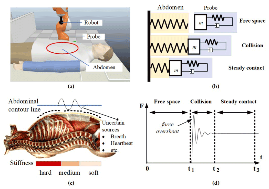
Figure 2Problem description. (a) Robot-assisted ultrasonic examination system. (b) Modelling the dynamic relationship between the US probe and the patent's abdomen. (c) Uncertain sources (breath, heartbeat, etc.) and variable stiffness characteristics of human surface tissue. (d) The three stages of contact force during US scanning.
1.4 Contribution
Based on these observations, this paper aims to design a position-impedance hybrid control scheme for the ultrasonic robot to scan the patient's abdomen laterally. The contributions of this work can be summarized as follows. (1) Based on the dynamic model of an ultrasonic robot, considering uncertainties and external disturbances, an adaptive backstepping position controller is proposed, which realizes acceptable trajectory tracking during the process of transverse ultrasonic scanning. (2) A variable adaptive hybrid impedance (VAHI) control scheme is proposed to avoid force overshoot and keep the accuracy of force tracking during the scanning. (3) The proposed VAHI control scheme and the classical adaptive impedance control method are compared and studied. The proposed control scheme has been further verified on the virtual robot experimental platform. This study shows that the efficiency provided by the proposed VAHI can meet the time-varying environment requirements, such as US acquisition, and its adaptability is far better than the traditional compliance control.
1.5 Outline
The paper is organized into five sections. Following the introduction, Sect. 2 introduces the framework of the robot-assisted ultrasonic examination system. Section 3 puts forward the VAHI and designs the position control and force control. In Sect. 4, the simulation comparison results are given to verify the theoretical results, so as to verify its superiority. Conclusions are drawn in Sect. 5.
2.1 Ultrasound robot scanning system
The main components of the autonomous robot ultrasonic scanning system are shown in Fig. 3. A manipulator equipped with ultrasonic probe is proposed to perform the required scanning and then display the captured ultrasonic images for the subsequent analysis. The robot ensures that the required trajectory is tracked and the appropriate force is maintained on the skin of the patient. In order to perform an abdominal ultrasound scanning, the patient should be in the supine position on the examination table. This paper models it as an elastic environment with varying stiffness. The ultrasound robot gently moves the probe over the patient's skin, generating a suitable force on the examined area.
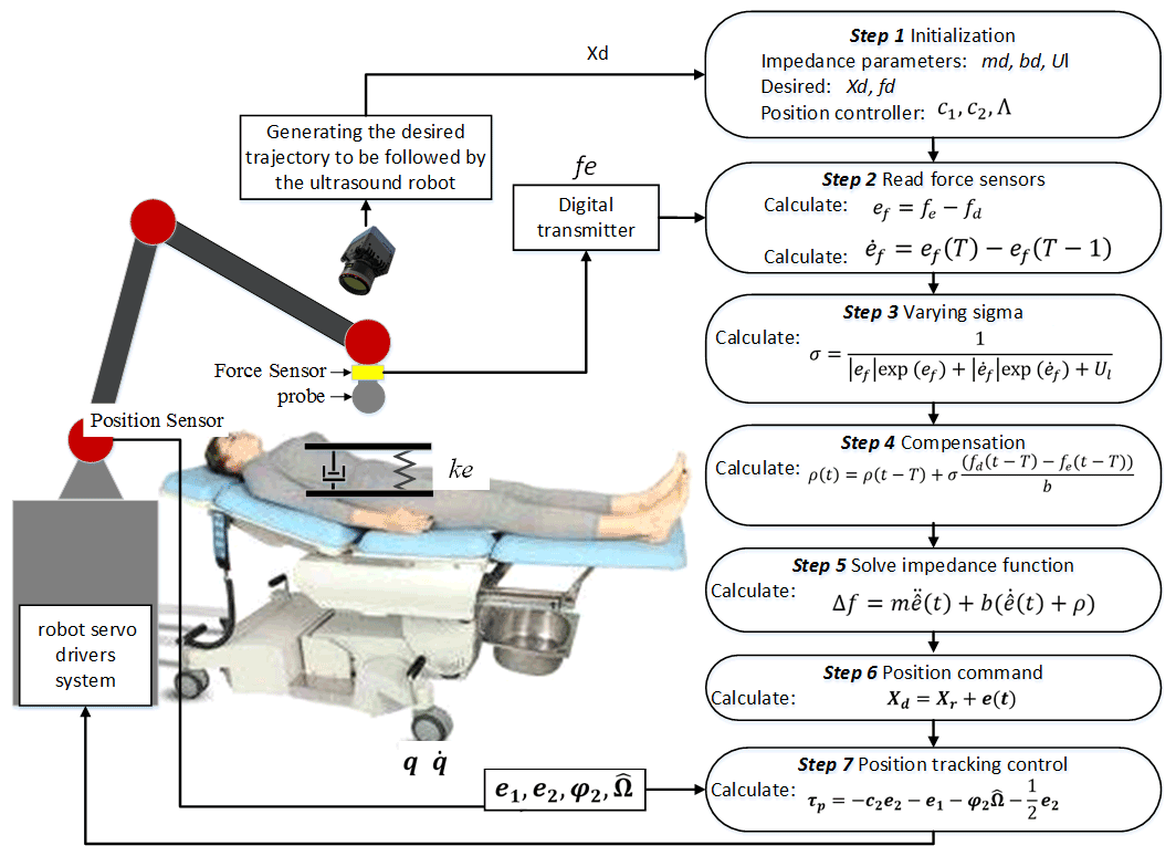
Figure 3Framework of robot-assisted ultrasonic examination system and the algorithm process.
The ultrasonic robot introduced in this paper is a six-axis rotary robot manipulator equipped with a US probe. The contact force is generated during pressing, and the deformation between the US probe and the patient's skin is measured by the force sensor installed at the end of the effector. The linear desired trajectory is generated to perform ultrasonic scanning on the abdominal region of the patient. The impedance controller calculates the position deviation by the deviation between the expected force and the actual force and sends it to the robot servo driver for tracking.
2.2 Dynamic model of constrained ultrasound robotic manipulator
The dynamic equation of the n joint robotic manipulator subjected to constraint is expressed as follows:
where are the vectors of the joint angles, angular velocity and angular acceleration, respectively. is the inertia matrix, denotes the effect of Coriolis and centrifugal forces, Gr(q)∈Rn is the gravitational effect, is the friction effects, τa∈Rn symbolizes the actuator torques, and τext is constraint torque. denotes the interaction force between the end-effector and environment. is the Jacobian matrix of the manipulator. d∈Rn is the external disturbances. T(q) is the position transformation matrix between the end-effector and the joints.

Figure 4Varying rate adaptive hybrid position–impedance control architecture. This is a cascade architecture in which the position controller tracks the position instructions generated by the impedance controller to achieve compliant interaction.
The unmodelled and external disturbances are bounded as follows:
where is a positive constant.
The patient's abdomen, with which the ultrasound robot interacts, is modelled as a spring with varying stiffness. Therefore, the force at the contact point is expressed as follows:
where is the stiffness matrix, and is the position of the contact point.
An adaptive hybrid position–impedance controller is designed to control the motion and interaction force of the ultrasonic robot. The controller is designed to ensure that the desired trajectory can be tracked when there are unknown parameters and external disturbances in the ultrasonic scanning process. At the same time, the controller is used to avoid force overshoot and keep the force-tracking accuracy on the patient's skin, so as to obtain a clear scanning image. As shown in Fig. 4, the control framework is based on the implementation of task constraints. The robot is able to move its own end-effector with a desired position xd and interact with the environment. The generated interaction force fe between robot and environment is measured by a force sensor which is attached to the end-effector of the robot. The force error between the desired force and the generated interaction force is then sent to the force controller to generate the corresponding position error. Then, robot's position controller closely achieves the reference position tracking.
3.1 Position controller
Abbas et al. (2021) proposed a backstepping adaptive controller design scheme for the motion tracking of an ultrasonic robot under uncertain disturbances. Therefore, this paper adopts this scheme to design the position controller. The dynamic model of the n joint ultrasound robot is converted to the state-space feedback form as follows:
where ; are the system state vectors.
The state error is defined as follows:
where α1 is the virtual control vector throughout the backstepping design process, to ensure that the robot angular position q can track the desired trajectories qd in the existence of unknown parameters and external disturbances.
Step 1. The derivation of the variable e1 is as follows:
Then, we choose the Lyapunov function candidate as follows:
By differentiating Eq. (12) and substituting Eq. (11), the derivative of the Lyapunov function becomes the following:
The virtual control law can be designed as follows:
where is a positive gain matrix.
Table 1Comparison of hybrid impedance (HI), adaptive hybrid impedance (AHI), and VAHI schemes in the steady force tracking stage.
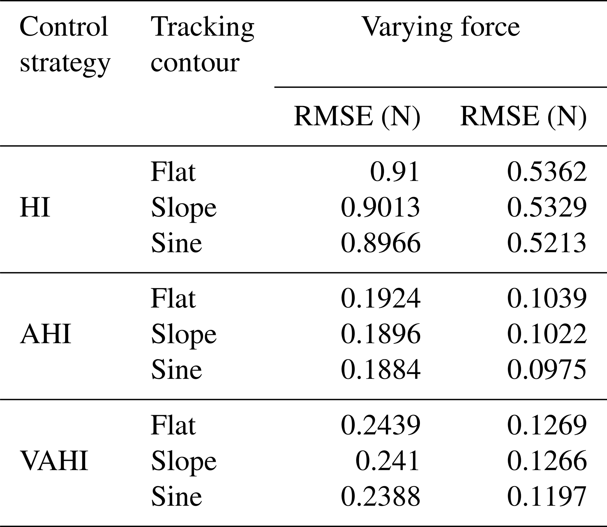
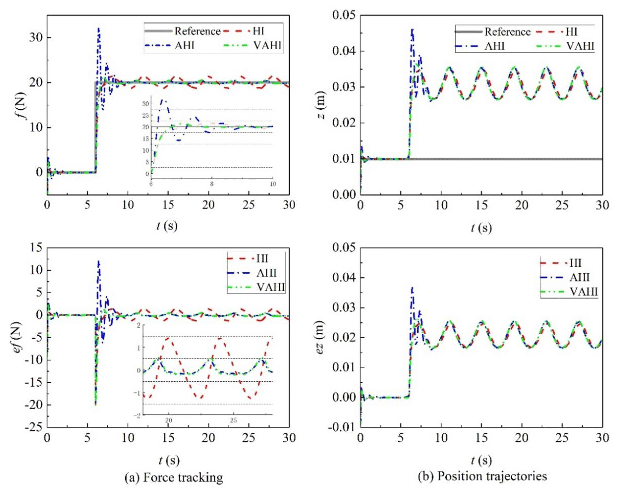
Figure 5Tracking of the constant force with HI, AHI, and VAHI control schemes in the flat surface.

Figure 6Tracking of the constant force with HI, AHI, and VAHI control schemes in the slope surface.
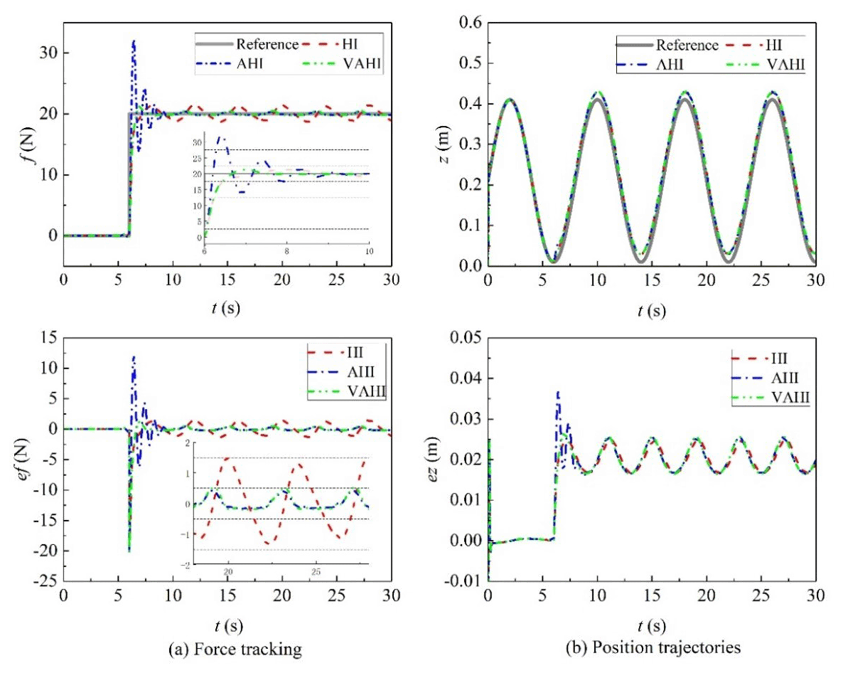
Figure 7Tracking of the constant force with HI, AHI, and VAHI control schemes in the sine surface.
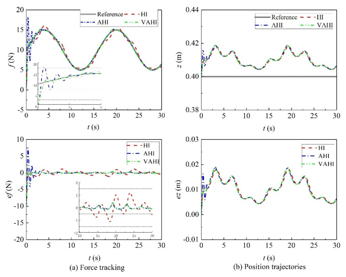
Figure 8Tracking of the varying force with HI, AHI, and VAHI control schemes in the flat surface.
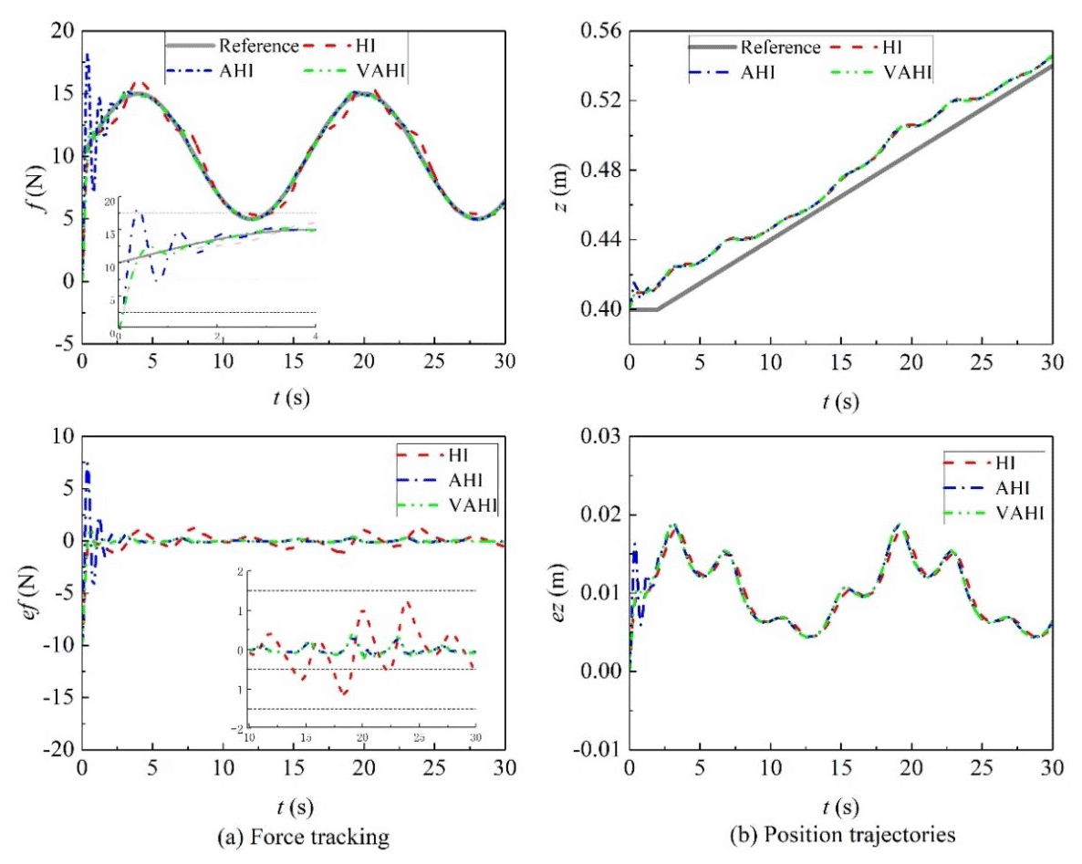
Figure 9Tracking of the varying force with HI, AHI, and VAHI control schemes in the slope surface.
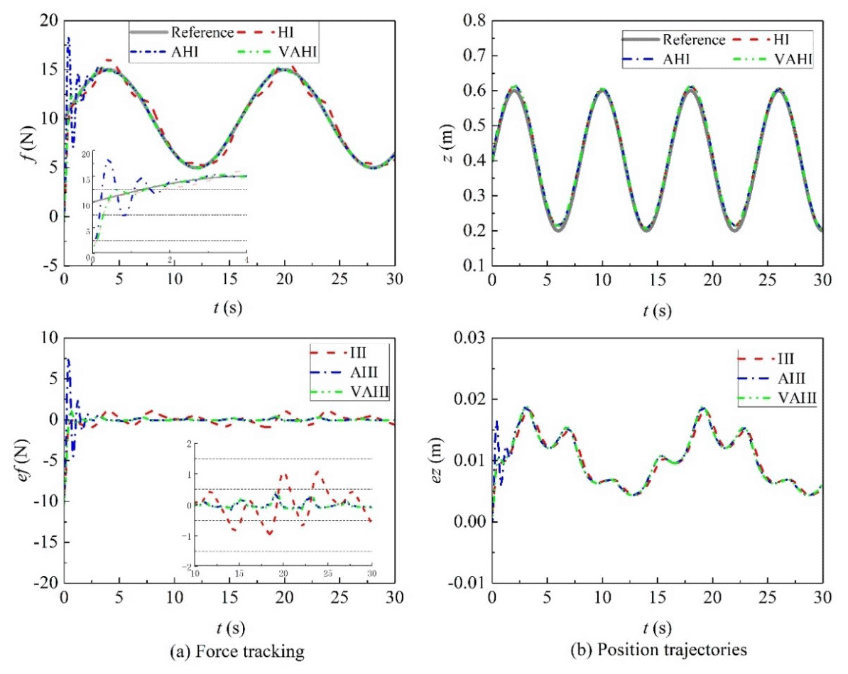
Figure 10Tracking of the varying force with HI, AHI, and VAHI control schemes in the sine surface.
Therefore, in the following:
If e2 = 0, then is ND (negative definite), and the convergence of the e1 can be guaranteed.
Step 2. The derivation of e2 is expressed as follows:
where .
The inertia matrix Mr(q) is symmetric and positive definite in robot dynamics. Hence, choosing the Lyapunov function candidate combined with V1 is as follows:
The derivative of V2 is obtained as follows:
In robot dynamics, the matrix is skew symmetric for any arbitrary w∈Rn which satisfies the following: . Using this property, Eq. (18) becomes the following:
The term can be formulated, based on Eqs. (10) and (16), as follows:
The unknown parameters on the right side of Eq. (20) can be parameterized as follows:
where is a known function which can be obtained from the sensory feedback. Ω is the vector of unknown nonlinear parameters. The direct adaptive technique can be utilized to estimate the unknown dynamic parameters.
A new Lyapunov function which considers the estimation errors is constructed as follows:
where , is the estimation of the unknown parameters Ω. Λ is an arbitrary positive definite matrix.
By differentiating Eq. (22), the following is achieved:
Using , Eq. (23) becomes the following:
The design parameter update rate is as follows:
The derivative of the Lyapunov function in Eq. (25) becomes the following:
Applying Young's inequality results in the following:
Then, Eq. (26) satisfies the following inequality equation:
The position control law can be designed as follows:
where is a positive gain matrix.
By substituting Eq. (29) into Eq. (26), we derive the following:
Therefore, the above equation satisfies the input to state stability (ISS). Selecting the appropriate controller parameters can make positional tracking errors for the ultrasound robot converge to a small value.
Mapping from the joint space to the Cartesian space by the following transformation results in the following:
where x and xd are the actual and desired end-effector position, respectively. S is a compliance selection matrix that specifies the position or force control degrees of freedom.
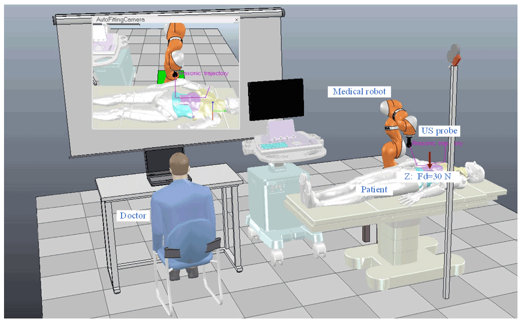
Figure 11The V-rep set-up for the ultrasound robot abdominal ultrasonography. A KUKA light-weight robot (LWR) is utilized to conduct the scan of the patient's abdomen in a more realistic manner.
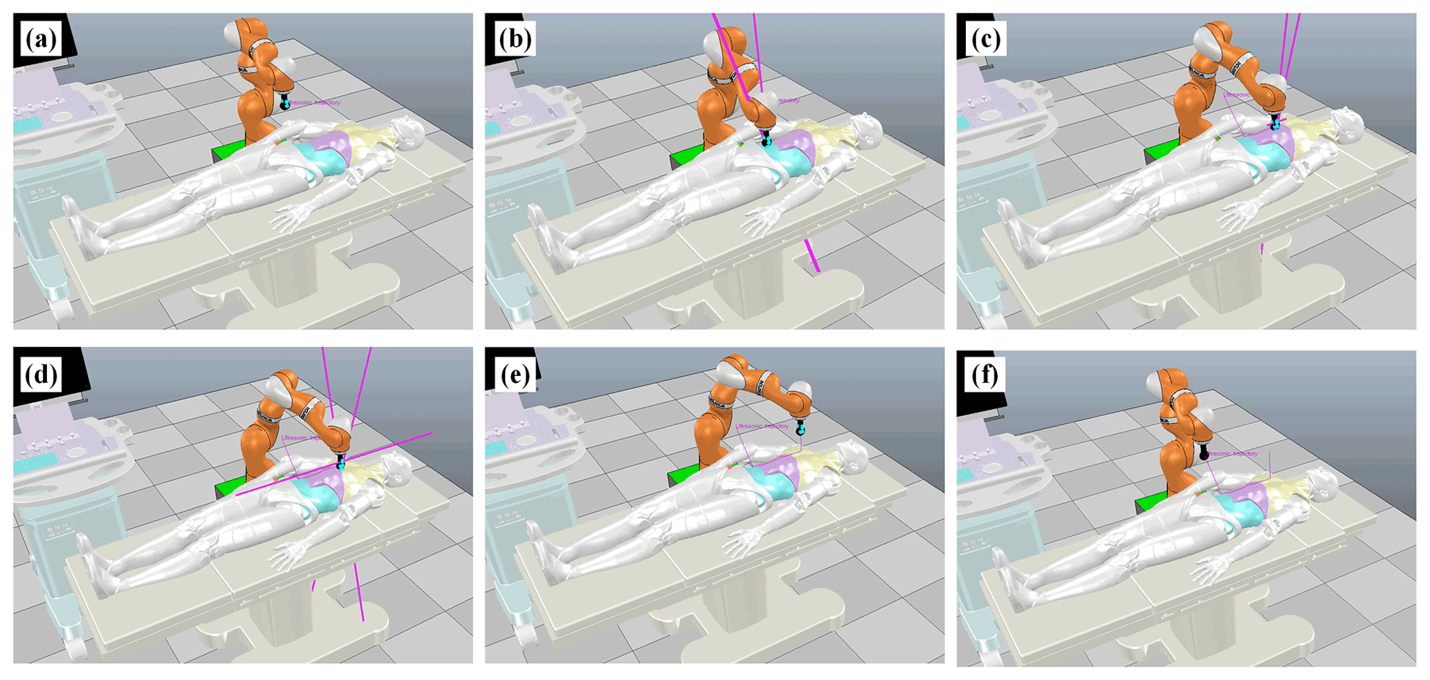
Figure 12Validation results of the KUKA LWR during the scanning process of the straight line trajectory. (a) Initial position of the US probe. (b) The abdomen (soft). (c) The belly (middle stiffness). (d) The chest (hard). (e) Leaving the patient. (f) Final position of the US probe.
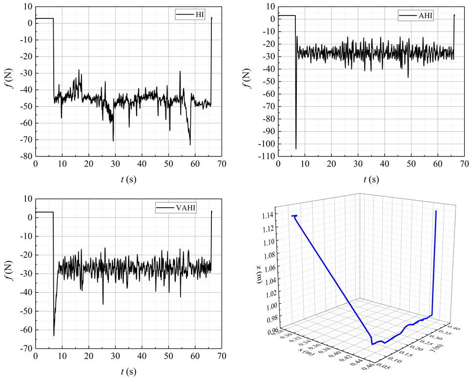
Figure 13Tracking of the constant force with HI, AHI, and VAHI in the V-rep ultrasonic scenario.
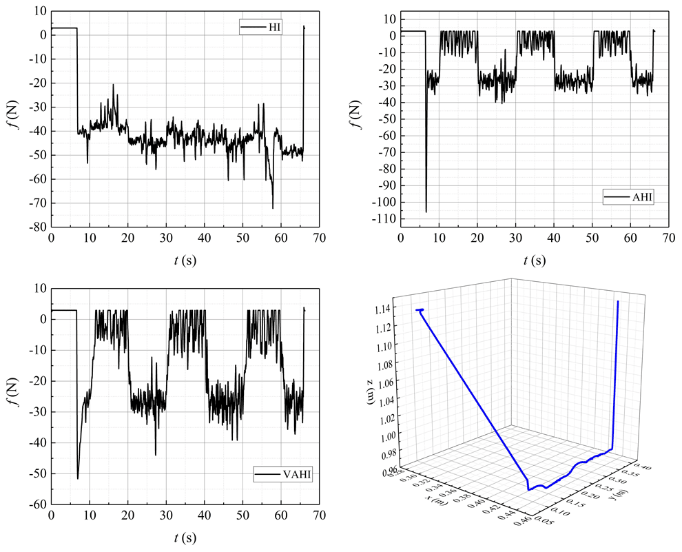
Figure 14Tracking of the varying force with HI, AHI, and VAHI in the V-rep ultrasonic scenario.
3.2 Force controller
Considering the actual complex environment of patient examination area, it is a nonlinear environmental contact model. In order to improve the force-tracking accuracy, an improved adaptive algorithm is proposed to solve this problem. Considering the force constraint in one direction (usually the z direction), the adaptive hybrid impedance control is expressed by the following formula:
m and b represent the inertia and damping parameters of the desired impedance, respectively. Where ρ is the compensation law, is the estimation position error of actual position error e(t). is the force error between the desired force fd and actual contact force fe. The adaptive compensating law can be designed as follows:
In the initial conditions, ρ(0)=0, T is the sampling period of the impedance controller, and fd and fe are desired and actual contact force, respectively. σ is the update rate. On the basis of Sect. 3.1, the ultrasound robot can already achieve a better motion-tracking ability. Therefore, this part mainly analyses the control performance of impedance controller.
Rewriting Eq. (33), and marking , the ρ can be expanded as follows:
Substituting Eq. (34) into Eq. (32) yields the following:
Take the Laplace transform of Eq. (35), using . Then, the steady transfer function is as follows:
The force-tracking error transfer function Φ(s) is shown below, as follows:
It can be seen that the tracking error can be decreased by increasing σ.
For transient response analysis, due to the collision process being extremely short, n is no longer an infinite number. Hence, rewriting the compensation part of Eq. (33) leads to the following:
It can be approximated that . The function representation between ρ(t) and c(t) is as follows:
Substituting Eq. (39) into Eq. (32) leads to the following:
The transient response transfer function Ψ(s) is as follows:
The damping coefficient ζ is a vital parameter about the oscillation form and can be calculated as follows:
It can be clearly seen that the system can present oscillation by increasing σ, which indicates smaller σ smaller force overshoots.
So, the comprehensive analysis results from Eqs. (37) and (42) show that keeping the σ unchanged is unadvisable choice. Therefore, in order to avoid force overshoots and keep force tracking in a steady state, a varying update rate need to be carefully designed.
A dynamic calculating the update rate is designed as follows in the paper:
The update rate σ is modified online using the following feedback information, where the force error is ef, and the force error variation . Ul is the upper limit. The VAHI controller is proposed to compensate for the force-tracking error caused by changed environment and to be certain that there are no force overshoots by adjusting σ.
To investigate the effectiveness of the proposed control strategy, the simulation test, using a 6 degrees of freedom (DOF) Programmable Universal Machine for Assembly (PUMA) 560 robot, is conducted. The specifications of the robot and the required abdomen scan are explained in Sect. 2. Applied forces are considered in two cases, i.e. the constant force 20 N and sine force 10 ± 5 N in the z direction. The goal is to validate its tracing performance as much as possible.
The simulation runs are conducted using MATLAB and Robotics Toolbox (designed by Peter Corke; https://petercorke.com/toolboxes/robotics-toolbox/, last access: 20 June 2022). The sampling time is 0.01 s. The initial values of the estimated parameter vectors are selected to be half of the actual values, the selection matrix , and the position controller parameters , , . The position and force controller gains are tuned based on the trial and error method to maintain acceptable system performance. The basic impedance parameters and are selected based on experience (see Eq. 32, which here refers to the benchmark). To ensure stability and contrast, the selection of σ for controllers is as follows: in hybrid impedance (HI), it is 0, whereas in adaptive hybrid impedance (AHI), it is 0.5. For VAHI, it is set at range of 0 to 0.5 by the upper limit. To test the performance and adaptability of various strategies in a dynamic continuous stiffness environment, we apply the following:
4.1 Comparison study
A comparative study between the proposed control strategy VAHI and the traditional impedance controller HI and AHI is carried out in the presence of unknown parameters and external disturbances. Figures 5, 6, and 7 show the simulation results of hybrid impedance (HI), adaptive hybrid impedance (AHI), and VAHI for a constant force tracking on a flat surface, slope, and sine surface, respectively. Figures 8, 9, and 10 show the simulation results of HI, AHI and VAHI for a varying force tracking on a flat surface, slope, and sine surface respectively.
In the contact stage, Figs. 5a, 6a, and 7a show that, no matter what the tracking environment is, AHI has a greater overshoot than other two methods. The overshoot exceeded 12 N, and the overshoot ratio reached 40 %. If the control method is applied in practice, it will greatly affect the quality of image acquisition and may even threaten the safety of patients. On the contrary, if the overshoot is small or there no overshoot in HI and VAHI, the overshoot is within 1 N. The value is a very safe value, and the patient will feel comfortable during the contact.
In the steady-state tracking stages in Figs. 5b, 6b, and 7b, the results show that AHI and VAHI can both achieve a super force tracking ability. The max tracking error is 0.5 N, and the force tracking accuracy is 2.5 %. This can greatly ensure the image quality for robot ultrasonic imaging in the long-time acquisition process. However, for the HI controller, its tracking accuracy is 1.5 N, and the force tracking accuracy is 7.5 %, which has a great impact on the stability and quality of the image. This means that the adaptive solution can improve the force control accuracy by about 3 times.
The root mean square error (RMSE) is calculated to analyse the performance of the control strategy and is defined as follows:
From Table 1, it can be observed that the proposed VAHI strategy still provides a superior tracking accuracy with a smaller error deviation, as compared to HI. The RMSE is equal to 0.24, 0.19, and 0.9 N for the proposed VAHI scheme, AHI, and HI, respectively. Based on the root mean square error (RMSE) results, compared with HI, the force-tracking effect of VAHI and AHI is also excellent.
Therefore, a conclusion can be drawn from the above analysis. HI is more suitable for the contact stage, while AHI is more suitable for the tracking stage. To combine the best of both, therefore, the VAHI control strategy is the best choice to achieve a better force controller, i.e. high force tracking without overshoot. It can maintain good acoustic contact and avoid excessive deformation.
4.2 Validation in V-rep
To further validate the proposed control scheme's performance, a KUKA light-weight robot (LWR) iiwa R800 (KUKA Roboter GmbH, Augsburg, Germany) is utilized to conduct the scan of the patient's abdomen in a more realistic platform, i.e. V-rep robot simulator. The advantage of this virtual platform can provide an effective solution to economize on cost and time and quickly examine the performance of different control schemes in various scenes before the implementation in a real situation. The KUKA manipulator is equipped with an ultrasound probe and a six-axis force sensor to simulate the ultrasound scanning task more realistically, as illustrated in Fig. 11. The proposed VAHI control scheme is developed with MATLAB software and linked with the V-rep simulation environment using the remote API. The movement of the manipulator is divided into two stages, namely the contact stage and the dynamic force-tracking stage. At the contact stage (0–10 s), it moves along the surface in a normal direction, i.e. z-axis direction to achieve the desired constant contact force (fd=30 N). At the dynamic force-tracking stage (10–60 s), the desired constant contact force must be maintained in z axis while tracking the target moving trajectory on x axis.
The initial state of the ultrasound robot has a certain height which has no contact between the US probe and the patient's skin; the whole motion process is shown in Fig. 12. It can be noted from Fig. 12 that the KUKA robotic arm successfully finishes the scan process under the proposed control scheme. The tracking of the desired constant and step force are depicted in Figs. 13 and 14, respectively. HI control strategy cannot make the contact force of the robot stable around 30 N, regardless of the tracking constant force or the step force, while AHI and VAHI can make the contact force stable around the given tracking force, indicating that HI cannot achieve force-tracking control in a dynamic environment. With the AHI control strategy, the overshoot force reached a terrifying 110 N immediately after the robot made contact with the patient, nearly 4 times the desired tracking force. For HI and VAHI, although there is an overshoot at the moment of contact, it is far less than the overshoot force generated by AHI strategy. Moreover, the proposed VAHI control scheme not only combines the advantages of the other two controllers but also perfectly avoids their respective disadvantages, which can avoid the force overshoots and keep the force-tracking accuracy during the scanning process. Once again, the validity of the VAHI controller is proved.
In this work, a varying rate hybrid position–impedance control strategy is designed to control an uncertain ultrasound robotic manipulator during the scanning process of the patient's abdomen. Based on an adaptive backstepping method, the precise position controller is realized. A comparison shows that the control scheme can avoid force overshoot and keep the tracking accuracy of the force during the scanning process. Simulation results show that the proposed control scheme has a better force-tracking capability and stronger applicability. Under the environment of V-rep, the proposed scheme is additionally verified with the KUKA robot. Future work will be devoted to implementing the proposed control scheme in real-world applications. This will be very promising and meaningful work because the proposed system can partly play the role of US sonographer and serve as a medical assistant to reduce their workload.
All the code/data used in this paper can be obtained upon request to the corresponding author.
ZX provided the ideas, reviewed the overall process for the work, and wrote the majority of the paper. ZY provided the simulation method, made the figures, and revised the paper.
The contact author has declared that neither they nor their co-author have any competing interests.
Publisher's note: Copernicus Publications remains neutral with regard to jurisdictional claims in published maps and institutional affiliations.
The authors are grateful for the financial support from the Natural Science Foundation of Shanxi Province, China (grant no. 201901D111300) and the Jinzhong Key Science and Technology Research and Development Project, China (grant no. Y211020).
This research has been supported by the Natural Science Foundation of Shanxi Province (grant no. 201901D111300).
This paper was edited by Mohamed Amine Laribi and reviewed by two anonymous referees.
Abbas, M., Al Issa, S., and Dwivedy, S. K.: Event-triggered adaptive hybrid position-force control for robot-assisted ultrasonic examination system, J. Intell. Robot. Syst., 102, 1–19, 2021.
Cao, H., He, Y., Chen, X., and Zhao, X.: Smooth adaptive hybrid impedance control for robotic contact force tracking in dynamic environments, Industrial Robot, 47, 231–242, https://doi.org/10.1108/IR-09-2019-0191, 2020.
Chatelain, P., Krupa, A., and Navab, N.: Confidence-driven control of an ultrasound probe: Target-specific acoustic window optimization, 2016 IEEE International Conference on Robotics and Automation (ICRA), IEEE, Stockholm, Sweden, 3441–3446, https://doi.org/10.1109/ICRA.2016.7487522, 2016.
Chaudhary, H., Panwar, V., Prasad, R., and Sukavanam, N.: Adaptive neuro fuzzy based hybrid force/position control for an industrial robot manipulator, J. Intell. Manuf., 27, 1299–1308, 2016.
Fang, T.-Y., Zhang, H. K., Finocchi, R., Taylor, R. H., and Boctor, E. M.: Force-assisted ultrasound imaging system through dual force sensing and admittance robot control, Int. J. Comput. Ass. Rad., 12, 983–991, 2017.
Geng, C., Xie, Q., Chen, L., Li, A., and Qin, B.: Study and analysis of a remote robot-assisted ultrasound imaging system, 2020 IEEE 4th Information Technology, Networking, Electronic and Automation Control Conference (ITNEC), IEEE, Chongqing, China, 1, 389–393, https://doi.org/10.1109/ITNEC48623.2020.9084796, 2020.
Göbl, R., Virga, S., Rackerseder, J., Frisch, B., Navab, N., and Hennersperger, C.: Acoustic window planning for ultrasound acquisition, Int. J. Comput. Ass. Rad., 12, 993–1001, 2017.
Graumann, C., Fuerst, B., Hennersperger, C., Bork, F., and Navab, N.: Robotic ultrasound trajectory planning for volume of interest coverage, 2016 IEEE international conference on robotics and automation (ICRA), Stockholm, Sweden, IEEE, 736–741, https://doi.org/10.1109/ICRA.2016.7487201, 2016.
Hennersperger, C., Fuerst, B., Virga, S., Zettinig, O., Frisch, B., Neff, T., and Navab, N.: Towards MRI-based autonomous robotic US acquisitions: a first feasibility study, IEEE Trans. Med. Imag., 36, 538–548, 2016.
Hogan, N.: Impedance control: An approach to manipulation: Part I – Theory, 107, 304–313, 1985.
Huang, Q., Wu, B., Lan, J., and Li, X.: Fully automatic three-dimensional ultrasound imaging based on conventional B-scan, IEEE Trans. Biomed. Circuit. Syst., 12, 426–436, 2018.
Kaminski, J. T., Rafatzand, K., and Zhang, H. K.: Feasibility of robot-assisted ultrasound imaging with force feedback for assessment of thyroid diseases, Medical Imaging 2020: Image-Guided Procedures, Robot. Int. Model., 11315, 113151D, https://doi.org/10.1117/12.2551118 11315, 2020.
Karamalis, A., Wein, W., Klein, T., and Navab, N.: Ultrasound confidence maps using random walks, Med. Image Anal., 16, 1101–1112, 2012.
Kojcev, R., Fuerst, B., Zettinig, O., Fotouhi, J., Lee, S. C., Frisch, B., Taylor, R., Sinibaldi, E., and Navab, N.: Dual-robot ultrasound-guided needle placement: closing the planning-imaging-action loop, Int. J. Comput. Ass. Rad., 11, 1173–1181, 2016.
Komati, B., Pac, M. R., Ranatunga, I., Clévy, C., Popa, D. O., and Lutz, P.: Explicit force control vs impedance control for micromanipulation, International Design Engineering Technical Conferences and Computers and Information in Engineering Conference, Am. Soc. Mech. Eng., 55843, V001T09A018, https://doi.org/10.1115/DETC2013-13067, 2013.
Li, K., Xu, Y., and Meng, M. Q. H.: An Overview of Systems and Techniques for Autonomous Robotic Ultrasound Acquisitions, IEEE Trans. Med. Robot. Bion., 510–524, https://doi.org/10.1109/TMRB.2021.3072190, 2021.
Mahmoud, M. Z., Aslam, M., Alsaadi, M., Fagiri, M. A., and Alonazi, B.: Evolution of Robot-assisted ultrasound-guided breast biopsy systems, J. Rad. Res. Appl. Sci., 11, 89–97, 2018.
Mathiassen, K., Fjellin, J. E., Glette, K., Hol, P. K., and Elle, O. J.: An ultrasound robotic system using the commercial robot UR5, Front. Robot. AI, 3, 1, https://doi.org/10.3389/frobt.2016.00001, 2016.
Merouche, S., Allard, L., Montagnon, E., Soulez, G., Bigras, P., and Cloutier, G.: A robotic ultrasound scanner for automatic vessel tracking and three-dimensional reconstruction of b-mode images, IEEE Trans. Ultras. Ferr. Freq. Con., 63, 35–46, 2015.
Mustafa, A. S. B., Ishii, T., Matsunaga, Y., Nakadate, R., Ishii, H., Ogawa, K., Saito, A., Sugawara, M., Niki, K., and Takanishi, A.: Development of robotic system for autonomous liver screening using ultrasound scanning device, 2013 IEEE international conference on robotics and biomimetics (ROBIO), Conference Location: Shenzhen, China, IEEE, 804–809, https://doi.org/10.1109/ROBIO.2013.6739561, 2013.
Pliego-Jiménez, J. and Arteaga-Pérez, M. A.: Adaptive position/force control for robot manipulators in contact with a rigid surface with uncertain parameters, Europ. J. Con., 22, 1–12, 2015.
Priester, A. M., Natarajan, S., and Culjat, M. O.: Robotic ultrasound systems in medicine, IEEE Trans. Ultras. Ferr. Freq. Con., 60, 507–523, 2013.
Raibert, M. H. and Craig, J. J.: Hybrid position/force control of manipulators, ASME, J. of Dynamic Systems, Measurement, and Control, 103, 2–12, https://doi.org/10.1115/1.3139652, 1981.
Raiola, G., Cardenas, C. A., Tadele, T. S., De Vries, T., and Stramigioli, S.: Development of a safety-and energy-aware impedance controller for collaborative robots, IEEE Robot. Autom. Lett., 3, 1237–1244, 2018.
Shams, R.: Deformation Estimation and Assessment of Its Accuracy in Ultrasound Images, Concordia University, 2017.
Siciliano, B., Sciavicco, L., Villani, L., and Oriolo, G.: Modelling, planning and control, Advanced Textbooks in Control and Signal Processing, Springer Science & Business Media 2009.
Swerdlow, D. R., Cleary, K., Wilson, E., Azizi-Koutenaei, B., and Monfaredi, R.: Robotic arm–assisted sonography: Review of technical developments and potential clinical applications, Am. J. Roentgenol., 208, 733–738, 2017.
Tsumura, R. and Iwata, H.: Robotic fetal ultrasonography platform with a passive scan mechanism, Int. J. Comput. Ass. Rad., 15, 1323–1333, 2020.
Ulrich, C. and Struijk, L. N. S. A.: Probe contact forces during obstetric ultrasound scans-A design parameter for robot-assisted ultrasound, Int. J. Indust. Ergon., 86, 103224, https://doi.org/10.1016/j.ergon.2021.103224, 2021.
Virga, S., Zettinig, O., Esposito, M., Pfister, K., Frisch, B., Neff, T., Navab, N., and Hennersperger, C.: Automatic force-compliant robotic ultrasound screening of abdominal aortic aneurysms, 2016 IEEE/RSJ International Conference on Intelligent Robots and Systems (IROS), Conference Location: Daejeon, Korea (South) IEEE, 508–513, https://doi.org/10.1109/IROS.2016.7759101, 2016.
Virga, S., Göbl, R., Baust, M., Navab, N., and Hennersperger, C.: Use the force: deformation correction in robotic 3D ultrasound, Int. J. Comput. Ass. Radiol., 13, 619–627, 2018.
Welleweerd, M. K., de Groot, A. G., de Looijer, S. O. H., Siepel, F. J., and Stramigioli, S.: Automated robotic breast ultrasound acquisition using ultrasound feedback, 2020 IEEE International Conference on Robotics and Automation (ICRA), Paris, France IEEE, 9946–9952, https://doi.org/10.1109/ICRA40945.2020.9196736, 2020a.
Welleweerd, M. K., Siepel, F. J., Groenhuis, V., Veltman, J., and Stramigioli, S.: Design of an end-effector for robot-assisted ultrasound-guided breast biopsies, Int. J. Comput. Rad., 15, 681–690, 2020b.
Wu, S., Wu, D., Ye, R., Li, K., Lu, Y., Xu, J., Xiong, L., Zhao, Y., Cui, A., and Li, Y.: Pilot study of robot-assisted teleultrasound based on 5G network: A new feasible strategy for early imaging assessment during COVID-19 pandemic, IEEE Trans. Ultras. Ferr. Freq. Con., 67, 2241–2248, https://doi.org/10.1109/TUFFC.2020.3020721, 2020.