the Creative Commons Attribution 4.0 License.
the Creative Commons Attribution 4.0 License.
 | 07 Feb 2022
Kinematic and dynamic analysis of an omnidirectional mobile platform driven by a spherical wheel
Luis Daniel Filomeno Amador
Eduardo Castillo Castañeda
The increased use of spherical wheels has allowed mobile robots to have a higher degree of maneuverability, less complex path planning and less complex control schemes. The geometry and design of the mobile robot are the principal attributes that guarantee an omnidirectional motion. Furthermore, the platform uses an active spherical wheel and four passive spherical wheels to get the best stability when the robot uses a terminal element (Kärcher). The proposed model has been designed to improve the omnidirectional motion issues, such as vibration into the platform or lack of punctual contact between the wheel and the floor, compared to mobile robots using Mecanum wheels and more than one active wheel; due to the design concept, all the mathematical formulations, kinematics and dynamics presents how the models are validated with computer simulations.
- Article
(1958 KB) - Full-text XML
- BibTeX
- EndNote


As mobile robotics continues to evolve, its application has diversified from service robots to space exploration robots. In the development of the mobile robot, the designer focuses on the novelty of the final element, leaving out the mobile platform evolution. The chief problem with wheeled mobile robots is the restricted movement in workspace due to the necessity for system reorientation. Our goal is to get a wheeled mobile robotic system that can generate an omnidirectional displacement without the need to redirect the wheels, thus guaranteeing continuous operation. Additionally, this would allow the mobile robotic to operate in small spaces without the need of reorientation (Doroftei et al., 2007).
The design of the mobile platform is mainly constituted by geometric model and by the type of wheels used (Muir and Neuman, 1986). These characteristics are strongly related to kinematic analysis. The odometry technique uses a geometric body in a general framework to locate it later in any point of our reference. This is the principle that uses the odometry technique (Agull et al., 1987) that provides important applications as satellite locations, trajectory assignment and even artificial intelligence applications. Subsequently, after we get the position analysis, the velocity analysis is included within the same reference frame. The acceleration is defined as the change in velocity within a time range (Muir and Neuman, 1987).
Besides, we consider the masses of each element in the platform and as well as external forces to generate a dynamic model that can predict the motor's behavior.
Although there are platforms that have solved the omnidirectional problem (redirection of the mobile platform), its implementation requires a high construction cost and much more complex control systems. In the case of the Seekur robot (Roland, 2004), it uses eight motors to steer four active wheels and thus generates the omnidirectional movement of the platform. The Institute of Technology of Leibniz University Hannover in Germany developed another solution which implements three spherical active wheels, each one driven by two motors (Runge et al., 2014). The Robot Development Engineering Laboratory of Tohoko Gakuin University in Japan developed a newer solution, one that has a spherical active wheel driven by three motors with Swedish-type rollers (Kumagai, 2010). The AZIMUT robot (Clavien et al., 2018) represents a decentralized omnidirectional system. The Massachusetts Institute of Technology (MIT) presented a mobile platform that was supported by spherical wheels (West and Ascada, 1995) using rollers to transmit the movement with three active wheels. The reports mentioned above relate the fact that the geometry and type of wheels used are fundamental components in the design (Muir and Neuman, 1986), i.e., from triangular geometry (Orozco et al., 2020) to dodecagonal geometry (Orozco, 2018), using standard wheels (Muñoz et al., 2007), Swedish wheels (Lee et al., 2007) or spherical wheels (Ishida and Miyamoto, 2010).
The use of actuated spherical wheels in mobile platforms drastically simplifies the control of the robot, as well as the reduction of costs in its manufacture (Zhao BeMent, 1992). Kinematic and dynamic analysis ensures the effectiveness in the spherical wheel implementation (Angeles and Lee, 1988). Kinematics also allows for implementing the use of odometry to program robot movements as satellite location applications (Agull et al., 1987).
This paper is based on the kinematic and dynamic model of an omnidirectional mobile platform (OMP) with an active spherical wheel driven by two motors and four passive wheels as support. The kinematic and dynamic conditions are strongly linked with the geometry, the location of the wheels and with the position analysis of each wheel.
The Sheth–Uicker convention is used in the contact point between the wheel and the ground as planar contact (Muir and Neuman, 1987). This method presents the forward kinematics in an analogous way to manipulative robots. For the dynamic analysis, the Lagrange method is used where the Lagrangian is composed only of kinetic energy, because this method considers that the platform only moves on flat surfaces. The holonomic restrictions, which are directly linked with the movement of the platform, are raised within the operating frame of the robot, which guarantees that the “sweep” condition is wholly rejected. This strategy allows energy optimization in the actuators; in the same way, a more straightforward control is implied to achieve the system's omnidirectional movement.
This paper presents the kinematic and dynamic model of a mobile platform driven by one active spherical wheel constructed of rubber and four passive wheels built of steel; see Fig. 1. The design will be used in a cleaning robot (Fig. 2) (Orozco et al., 2020). The dimensions and weight are shown in Table 1. Some of the principal details are the Kärcher pressure system (used as a terminal element), the pan–tilt rotation (used as the reorientation's Kärcher system) and the robot's energy conversion system.

Figure 1The main feature of the model is the omnidirectional platform displacement. This characteristic allows us to generate a kinematic and dynamic model (Muir and Neuman, 1987).

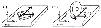
The kinematic analysis of a mobile robot is a direct analogy with the methodology used in manipulator robotics; the main differences between both systems are the restrictions and the type of joints used (d'Andrea-Novel et al., 1991).
In the manipulator model, most of the links are treated as solid bodies in the form of an open kinematic chain that generally uses rotational or prismatic joints (Angeles, 2007). When the modeling of the platform is presented, it is common to consider the system as n closed kinematic chains (the assign of the variable n is the number of wheels of the system with ground contact) (Yun and Yamamoto, 1993). The joint that generates the contact between the wheel and the ground is used as a contact of superior torque, which applies the Sheth–Uicker convention (Muir and Neuman, 1987). This allows us to consider the contact as a lower pair (planar contact).
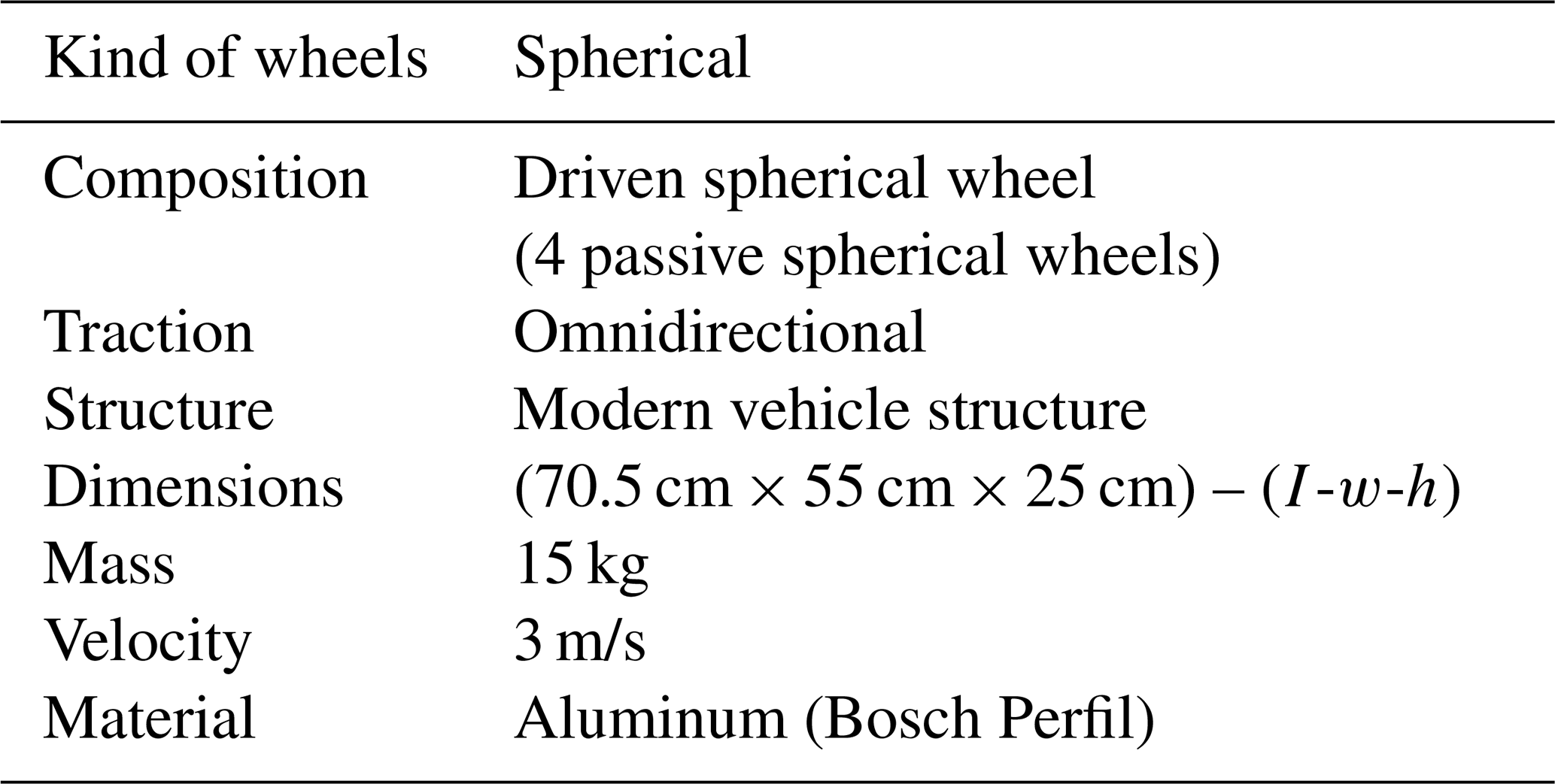
From the dynamic point of view, the analysis becomes more complex in that it becomes non-linear if the designer wants to contemplate all the system interaction effects (Zhao and BeMent, 1992). In this paper, the interactions that corrupt the linearity of the model are rejected. This is due to the movement of the platform, without any kind of interference, like vibration or any kind of external force. Figure 3 shows the elements that make up the mobile platform.
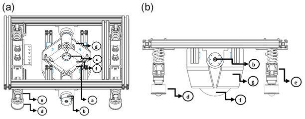
Figure 3The platform elements, with (a) platform top view and (b) platform side view. Labels: (a) roller, (b) motor, (c) roller ball (transfer), (d) roller ball (support), (e) support base, (f) active spherical wheel, and (g) active spherical wheel support.
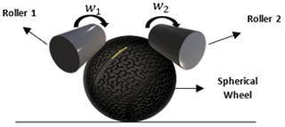
The platform has two DC (direct current) motors that by rollers (constructed of rubber) can transfer the angular velocity to the active spherical wheel; see Fig. 4. The platform also has a shock absorber system that guarantees the continuous actuated spherical wheel contact (Balkcom et al., 2009). The platform includes four roller-ball-type passive wheels implementing bearings as the mechanism of continuous contact with the ground.
3.1 Positional analysis
In this section, the coordinate system corresponding to the articulations of the mobile platform are assigned. As mentioned above, n closed kinematic chains are used where the variable n corresponds to the number of wheels that have contact with the ground; this contact is generated as a higher torque contact.
In this paper, the design implements the Sheth–Uicker convention (Muir and Neuman, 1987). The Sheth–Uicker convention model shows the high torque contact as a planar pair contact. See Fig. 5; as the result, we exclude the ambiguities of the transformation matrices.
After considering this convention, we apply each link's coordinate system in the proposed model (Barraquand and Latombe, 1989). The result is illustrated in Fig. 6, and the corresponding matrices are given in Eqs. (1), (2), (3) and (4). Where L1, L2, L3, L4, and O are the roller coordinate axes, and Cb, Ca, ma, mb, la, and lb are the dimensions of the platform (each letter indicates the dimension assignment). The matrices shown in Eqs. (1), (2), (3) and (4) describe the coordinate system from the central point R.
The matrices are shown in Eqs. (5), (6), (7) and (8), which present the relationship that exists between point R and point of contact O.

4.1 Kinematic analysis
Now that the positional analysis of the mobile robot is known, Eqs. (9) and (10) present the velocity analysis. As mentioned above, an omnidirectional platform is contemplated in conjunction with the manipulator element. The corresponding equations are presented as
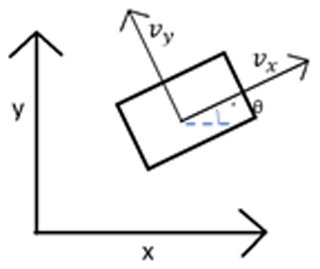
where w is the angular velocities of the motors, R is the radius of the roller with spherical wheel contact, Vx is the linear velocity in the x-axis direction, Vy is the linear velocity in the y-axis direction, and α is the roll inclination angle with x-axis reference.
The spherical wheel contact with the roller is considered continuous contact with a constant relation in speeds, where the slip that may exist in them is neglected. (This is just a consideration to develop the dynamical model to guarantee the linear model in the platform.)
We know the linear speed of the wheel is
From the above equation, we obtain
where wr is the angular spherical wheel velocity, and r is the spherical wheel radius.
After defining the relationships between the speed of the roller and the spherical wheel, we obtain
Considering the angular velocity obtained by the manipulator of the mobile robot, we get
where wk is the mobile robot's angular velocity.
In this way, the Jacobian matrix is
This analysis corresponds to the forward kinematics, and to obtain the inverse kinematics, we use
Equation (15) is justified by
As we can see from the Eq. (16) result, the J determinant is constant; it represents an advantage due to fact that the platform displacement does not present ambiguities.
4.2 Holonomic constraints
In this section, the restrictive dynamic equations are defined. We assumed the robot has one active wheel driven by two motors.
It is necessary to formulate an equation that guarantees that the mobile robot will roll and not slide.
Figure 7 shows the constraint diagram that guarantees the bearing, and we obtain
Restructuring the equations and representing them in a matrix way, we receive
From the previous equation, a solution condition can be proposed:
4.3 Dynamic analysis
In this section, the inverse dynamic equations are generated, where positions, speeds and motor accelerations are obtained. The Lagrange analysis is used in mobile robotic systems (Dhaouadi and Abu Hatab, 2013).
where i=1, 2, 3, 4; K is the total system's energy, τi is the generalized torque, λ1 and λ2 are Lagrange multipliers, rji represents the matrix R(θ) elements, S is the position vector, and is the velocity vector.
The total system's energy is given by
where KT is the translational energy, and KR is the rotational energy.
The potential energy is neglected because it is considered a horizontal not vertical displacement; therefore, U=0, (Li et al., 2015).
The translational energy is
where Mp is the platform mass, MRA is the active wheel mass, and MRP is the passive wheel mass.
On the other hand, the rotational energy is
where IR is the robot inertia tensor, IM is the spherical active wheel inertia tensor, and IW is the roller ball inertial tensor.
In this way, the energy equation that represents the mobile platform is generated:
Applying the Lagrange equation, we obtain
The dynamic model presented above describes the omnidirectional platform displacement considering the restrictions raised above. It is a single active wheel located in the platform mass center, which greatly simplifies the model.
5.1 Numerical kinematic validation
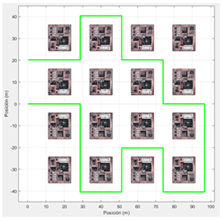
Validating the mobile platform kinematics consists of the linear velocity equation simulation (see Eqs. 9 and 10) to later integrate them and obtain the object's position, as shown below.
Figure 8 describes the mobile platform path to follow, and Fig. 9 describes the platform displacement.

5.2 Numerical dynamic validation
A scenario with a variable inclination slope is considered (Fig. 10). This gives the necessary torque to overcome the inclination force; the junction is considered a punctual rubber–concrete contact, and the friction coefficient is μT.
The mobile platform is considered to have a wheel activated by two motors, which implies the driven variable depends on w1 and w2.

Obtaining the necessary torque to overcome the Fr force and the Fg component that prevents the movement of the platform in the direction of F implies the use of Eqs. (20) and (21), considering the potential energy U, which is analytically expressed as
where L is the Lagrangian.
Equation (18) becomes
where τi −τl represents the generalized non-conservative forces (τi is the wheel torque, and τl is the friction contact torque), S is the position vector, and is the velocity vector.
By substituting the kinetic and potential energy equations in L, we obtain
where m is mass, g is acceleration, and h is height.
Obtaining h implies considering the height of the object when both w1 and w2 are active (see Fig. 11).

Therefore, we obtain
By replacing the values in L, we obtain
By substituting Eq. (28) into Eq. (27) and solving the Euler–Lagrange equation, we obtain
where α1 and α2 are the accelerations due to the rollers, X1 and X2 are the platform positions due to roller speed, μT is the dynamic friction coefficient, Fn is the normal force on the active wheel, and the equation simulations τ1 and τ2 are in Fig. 12.
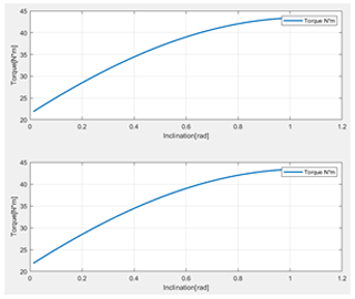
By validating the dynamic part, the equations were simulated where the following values are considered: Mp=10.1 kg, MRA=0.5 kg, MRP=0.4 kg, IR=diag (0.6895), and IM and IW=diag (0.0125). In this way the result in the dynamic model brings the congruence with the kinematic model. This reflects the Euler–Lagrange equation use with the omnidirectional mobile platforms.
Concluding, the design based on an active wheel and four passive wheels guarantees the omnidirectional displacement in the workspace with less complex design and construction.
In this paper, the kinematic and dynamic modeling of an omnidirectional mobile platform with an active wheel and four passive wheels was presented and validated. The active wheel uses two motors to generate its movement; the Sheth–Uicker convention was essential to locate each element of the mobile platform. In this way, the velocity analysis is summarized to simplify the position diagram and observe its change over time. The torque reflects the congruence with the kinematic equations, although the dynamic equation rejects the external forces.
The results generated in this article support the principle that a spherical wheel is the best option for a mobile platform when considering that the designer wants to build a land mobile robot. Due to the construction of this mobile platform, a smaller budget is required and less control in the programming of displacement is necessary.
The main code is publicly accessible and it can be found with an URL of Google Drive free access (https://drive.google.com/drive/folders/1iu_BgRKyBJKjBcNb_IZa3UMntX89XvYc?usp=sharing, Filomeno Amador and Castillo Castañeda, 2021).
LDFA and ECC discussed the methodology in the study, prepared the manuscript, and conceived and developed the kinematic–dynamic synthesis of the mechanism. Kinematic and dynamic analyses were performed by LDFA. ECC participated in developing the kinematic scheme and coordinated help in drafting the manuscript.
The contact author has declared that neither they nor their co-author has any competing interests.
Publisher’s note: Copernicus Publications remains neutral with regard to jurisdictional claims in published maps and institutional affiliations.
This paper was edited by Daniel Condurache and reviewed by three anonymous referees.
Agull, J., Cardona, S., and Vivancos, J.: Kinematic of vehicles with directional sliding wheels, Mech. Mach. Theory., 22, 295–301, 1987.
Angeles, J.: Fundamental of Robotics Mechanical Systems: Theory, Methods and Algorithms, 3rd Edn., Springer Science, Alemania, 2007.
Angeles, J. and Lee, S.: The formulation of dynamical equations of holonomic mechanical systems using a natural orthogonal complement, T. ASME, 55, 243–244, 1988.
Balkcom, D. J., Kavathekar, P. A., and Mason, M. T.: Time optimal trajectories for an omnidirectional vehicle, International Journal Robotics Research, 25, 985, https://doi.org/10.1177/0278364906069166, 2009.
Barraquand, J. and Latombe, J. C.: On non-holonomic niobile robots and optimal manoeuvring, Revue d'Intelligence Artificielle, Vol. 3-2, 77–103, 1989.
Clavien, L., Lauria, M., and Michaud, F.: Instantaneous centre of rotation-based motion control for omnidirectional mobile robots with sidewards off-centered wheels, Robot. Auton. Syst., 106, 58–68, 2018.
d'Andrea-Novel, B., Bastin, G., and Campion, G.: Modelling and control of non-holonomic wheeled mobile robots, in: Proceedings of 1991 International Conference on Robotics and Automation, 1130–1135, Sacramento, CA, 1991.
Dhaouadi, R. and Abu Hatab, A.: Dynamic modelling of differential-drive mobile robots using lagrange and newton-euler methodologies: a unified framework, Advances in Robotics & Automation, 2, 1000107, https://doi.org/10.4172/2168-9695.1000107, 2013.
Doroftei, I., Grosu, V., and Spinu, V.: Omnidirectional Mobile Robot-Design and Implementation, Gh. Asachi, Technical University of Iasi, Romania, 2007.
Filomeno Amador, L. D. and Castillo Castañeda, E.: Main Code KandD analysis, https://drive.google.com/drive/folders/1iu_BgRKyBJKjBcNb_IZa3UMntX89XvYc?usp=sharing, last access: 25 June 2021.
Ishida, S. and Miyamoto, H.: Ball wheel drive mechanism for holonomic omnidirectional vehicle, Kyushu Institute of Technology, Japan, 2010.
Kumagai, M.: A robot that balances on a ball, Robot Development Engineering Laboratory, IEEE Spectrum, 2010.
Lee, Y., Lee, D. V., Chung, J. H., and Velinslky, S. A.: Control of a redundant, reconfigurable ball wheel drive mechanism for an omnidirectional mobile platform, Robotica, 25, 385–395, 2007.
Li, Y., Ding, L., and Liu, G.: Attitude-based Dynamic and Kinematic Models for Wheels of Mobile Robot on Deformable Slope, Robot. Auton. Syst., 75, 161–175, 2015.
Muir, P. F. and Neuman, C. P.: Kinematic of wheeled mobile robots, The Robotics Institute, Carnegie Mellon University, Internal report CMU-RI-TR-86-12, 1986.
Muir, P. F. and Neuman, C. P.: Kinematic modeling for feedback control of an omnidirectional wheeled mobile robot, Proc. of the IEEE Conf. on R & A. Raleigh, North Carolina, 31 March–3 April, 1772–1778, 1987.
Muñoz, V., Gil-Gómez, G., and García, A.: Modelado cinemático y dinámico de un robot móvil omnidireccional, Dpto. Ingeniería de sistemas y automática, Universidad de Málaga, IV Course of automatic especialitation, 2007.
Orozco, E.: Desarrollo de un robot de servicio teleoperado para asistir en tareas de limpieza a alta presión, tesis de grado: Maestría en Tecnología Avanzada, CICATA-IPN Querétaro, available at: http://tesis.ipn.mx/handle/123456789/26542 (last access: 7 January 2022), 2018.
Orozco, E., Cafolla, D., Castañeda, E., and Carbone, G.: Static balancing of wheeled-legged hexapod robots, MDPI Journal Robotics, 9, 2–23, 2020.
Roland, S.: Introduction to autonomus mobile robots, Massachusetts Institute of Technology, 2nd Edn., A Bradford book, ISBN 0-262-19502-X, 2004.
Runge, B., Borchert, G., and Raatz, A.: Design of a Holonomic Ball Drive for Mobile Robots – A potential alternative to a Mecanum wheel. Lecture, Leibniz Universität Hannover, 2014.
West, M. and Asada, H.: Design and control of ball wheel omnidirectional vehicles, Department of mechanical engineering, MIT, Proceedings of 1995 IEEE International Conference on Robotics and Automation, 2, 1931–1938, 1995.
Yun, X. and Yamamoto, Y.: Internal dynamic of a wheeled mobile robot. Proc. Of the 1993 IEEE/RSJ International Conference on Intelligent Robots and System, 1288–1294, Yokohama, Japan, 1993.
Zhao, Y. and BeMent, S.-L.: Kinematics, dynamics and control of wheeled mobile robots, Proc. Of the 1992 IEEE International Conference on Robotics and Automation, 91–96, Nice, France, 1992.