the Creative Commons Attribution 4.0 License.
the Creative Commons Attribution 4.0 License.
 | 17 Mar 2022
A novel flying–walking power line inspection robot and stability analysis hanging on the line under wind loads
Xinyan Qin
Bo Jia
Jin Lei
Jie Zhang
Huidong Li
Bo Li
Zhaojun Li
To address the problems of existing power line inspection robots (PLIRs), such as complex structural design, difficult landing on and off lines, short cruise times, and easy hitting lines, we propose a novel flying–walking power line inspection robot (FPLIR) with the ability to fly and walk. The structural design of an FPLIR is carried out, which mainly includes a flying mechanism and a walking mechanism. Compared with climbing PLIRs and unmanned aerial vehicles (UAVs), the FPLIR can quickly land on and off lines, easily cross obstacles, and have longer cruise times and steady inspection perspectives. In addition, a directing-push pressing component is designed to improve the walking stability along the line. We also investigate the walking stability of the FPLIR on the line when encountering working conditions with crossing wind. The dynamics model of the FPLIR on the power line using the Lagrangian equation is derived to analyze walking stability caused by wind loads, considering pressing force and walking speed. An optimized regression design with three factors (wind angle, walking speed, and pressing force) and five levels was adopted to reveal the effect of these factors on the walking stability of the FPLIR. The experimental results show that wind angle and pressing force significantly influence the walking stability of the FPLIR (P<0.05). The maximum swing displacement of the center of mass (COM) is 4.7 cm (when wind angle, walking speed, and pressing force are 90∘, 7.2 m min−1, and 0, respectively). The maximum swing displacement of the COM is 2.5 cm when the pressing force increasing to 39.4 N is reduced by 46.2 % (when wind angle and walking speed are 90∘ and 5.1 m min−1, respectively), which effectively reduces the influence of wind loads and improves the stability of the FPLIR. The proposed FPLIR significantly improves inspection stability, providing a theoretical basis for slipping control, collecting images of intelligence inspection robots in the future.
- Article
(6883 KB) - Full-text XML
- BibTeX
- EndNote


Power lines exposed to the natural environment for a long time might have incurred some failures such as broken strands, vegetation encroachment, and damper slipping, affecting transmission capability and the safety of the power system. Therefore, it is essential to conduct regular inspections and maintenance to prevent power lines from losing transmitting power and causing security problems.
The original inspection method of power lines is manual inspection (Karjalainen et al., 2016). Manual inspection mainly relies on inspectors climbing line towers or using telescopes to inspect power lines. This method has heavy inspection intensity and low inspection accuracy (Wang et al., 2009). Therefore, people strive to develop all kinds of advanced power line inspection robots (PLIRs) to replace humans. Inspection robots have been widely used to reduce inspection intensity, improve inspection accuracy, and prevent accidents caused by manual inspection (Yang et al., 2020; Alhassan et al., 2019; Menendez et al., 2017; Seok and Kim, 2016; Luo and Tian, 2011; Jalal et al., 2013). At present, inspection robots can generally be classified into three categories, i.e., climbing PLIRs, flying PLIRs, and hybrid PLIRs (Alhassan et al., 2019). Their inspection features and workplaces are illustrated in Fig. 1.
Climbing PLIRs are typically characterized as two or more mechanical arms that climb and roll along the power line (Wang et al., 2011a, b). Paulo et al. (2008) developed a climbing robot that installed a telescopic adjustment mechanism to adjust the center of gravity to complete crossing of obstacles (Debenest and Guarnieri, 2010; Fonseca et al., 2008). Montambault and Pouliot (2015) designed the climbing inspection robot characterized as a clamping mechanism to cross obstacles (Pouliot and Montambault, 2012; Montambault and Pouliot, 2015). Wuhan University proposed a two-armed mobile robot to achieve autonomous motions (e.g., walking and crossing obstacles) on power lines (Wang et al., 2011b). Moreover, other types of climbing PLIRs include three-armed PLIRs (Yang et al., 2014; Tao and Fang, 2019), four-armed prototypes (Lima et al., 2018), five-armed structures (Tao et al., 2016; Shruthi et al., 2019), and snake-shaped mechanisms (Wei et al., 2013; Liu et al., 2019). Climbing PLIRs are more stable and reliable for performing inspection tasks, but their structural design is complicated, and they have more difficulty in crossing certain obstacles.
Flying PLIRs use unmanned aerial vehicles (UAVs) or helicopters to inspect power lines. Helicopters are initially used in the power transmission and distribution industry (Yan et al., 2008; Whitworth et al., 2001; Jones et al., 2000; Browne and Adam, 1988; Pelacchi, 1998). Helicopter inspection can quickly complete inspection tasks and dramatically reduce the inspection intensity. However, helicopter inspection is greatly affected by the complex operating environment and bad weather. For example, pilots need to be trained, and ground equipment needs to be maintained, meaning that this inspection method is costly and weather-dependent. Compared with helicopter inspection, UAV inspections have lower cost, excellent flight stability, and suspension capability (Hrabar et al., 2010; Wang et al., 2010; Zhang et al., 2012; Li et al., 2014; Luque-Vega et al., 2014; Qiu et al., 2018; Jiang et al., 2018). However, UAV inspections are highly vulnerable to the influence of wind and short cruise times. The short cruise time has limited its application to long-distance inspection tasks (Qin et al., 2018).
Hybrid PLIRs combined climbing and flying functions and were presented in Katrašnik et al. (2010), Chang et al. (2017), and Miralles et al. (2018). The flight ability is utilized to carry the PLIRs to the power line or to cross obstacles; the climbing mechanism moves the robot along the power line for the inspection task. Katrašnik et al. (2010) proposed a new climbing–flying robot and developed a walking mechanism installed under the flying mechanism (Buskey et al., 2001). Yu et al. (2015) designed a flying–sliding inspection robot with flying and sliding functions along the power line, achieving self-stabilization of the robot (Abd-Elaal et al., 2018). François et al. (2018) proposed a multi-rotor inspection robot, which can carry a payload (5 kg) and land semi-automatically on the power line (Eisenbeiss, 2009). Chang et al. (2017) designed a hybrid model inspection robot (Xie et al., 2019). Compared with other PLIRs, hybrid PLIRs integrate a walking mechanism and a flying mechanism to quickly land on and off lines and cross obstacles.
In addition, a power line is installed at a height of 50–65 m from the ground in western China, leading to the power line having lower structural damping and higher flexibility characteristics. Therefore, the power line is sensitive to the influence of environmental factors (e.g., wind, ice cover, and temperature difference). In addition, PLIRs on the power line are greatly affected by wind. Thus, it is crucial to study the impact of wind on the PLIRs. At present, Alhassan et al. (2019) have analyzed the impact of different wind angles on the walking vibration (Alhassan et al., 2019). Wang et al. (2009) analyzed wind load influence on robot structure and optimized the parameters (Wang et al., 2009). Fan et al. (2018) studied the speed and angle of the wind on the inspection robot, but the wind loads affecting its walking stability were not considered (Fan et al., 2018).
Our study proposes a novel flying–walking power line inspection robot (FPLIR) to analyze walking stability on the power line under wind loads. The main contributions of this paper are as follows. (1) A novel FPLIR with the ability to fly and walk is proposed to quickly land on and off the line, easily cross obstacles along the line, and get a steady inspection perspective of the line. (2) A directing-push pressing component is designed to improve the walking stability and inspection reliability along the line. (3) A dynamics model of the FPLIR hanging on the power line is derived to analyze the walking stability under wind loads. A three-factor, five-level test was designed to reveal the influence of each factor on the walking stability of the FPLIR.
The rest of the paper is organized as follows. The second section introduces the mechanism design and dynamics model of the walking mechanism. The third section focuses on the simulation analysis and dynamics model of the FPLIR on the power line. The experiment of the FPLIR walking stability is designed in the fourth section. The fifth section presents the experimental results and analysis. The summary and conclusion are given in the sixth section.

2.1 Mechanical structure design
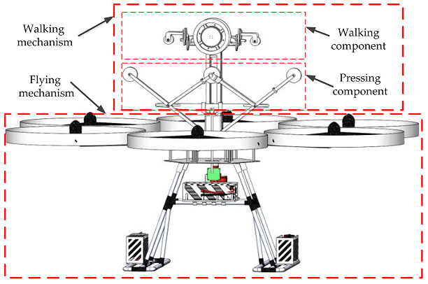
The mechanical structure of the FPLIR is shown in Fig. 2. The FPLIR has two mechanisms, i.e., a flying mechanism and a walking mechanism. The overall size of the FPLIR is 1.250 m × 1.250 m × 1.200 mm (length, width, and height). The flying mechanism is powered by the multi-rotor to land on and off power lines and cross obstacles. The walking mechanism is powered by a driving motor to walk along the power line. The walking mechanism includes a walking component and a pressing component. The walking component is shown in Fig. 3. The pressing component provides pressing force when the FPLIR walks along the power line.
The schematic diagram of the flying mechanism is shown in Fig. 4, which mainly consists of a controlling box, a flying part, batteries, and an undercarriage. The controlling box is divided into two layers, which consist of three carbon fiber plates and aluminum columns.
The undercarriage assembled of carbon fiber tubes is installed at the bottom of the controlling box to bear the weight of the FPLIR and provide installing locations for three batteries. The function of the flying mechanism is to land on and off lines and to cross obstacles (e.g., tower and crossing wire clamp).
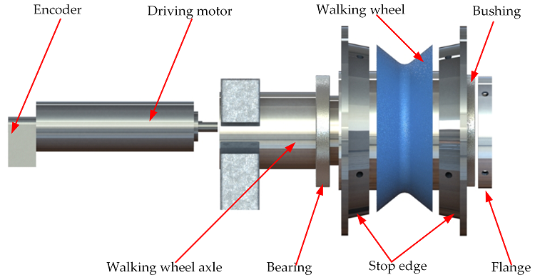
The walking component mainly includes a walking wheel, two auxiliary wheels, and a driving motor in Fig. 5.
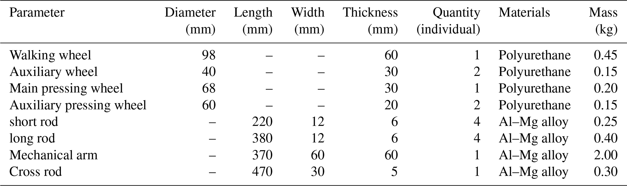
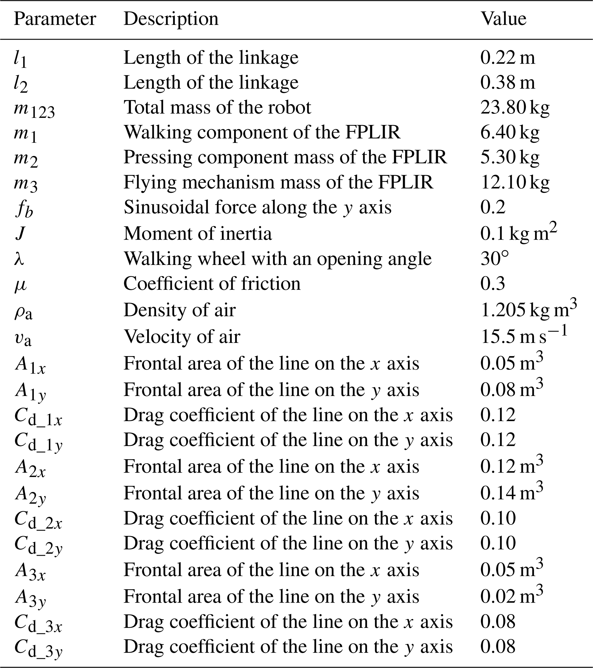
The pressing component mainly consists of three pressing wheels (a main pressing wheel and two auxiliary pressing wheels), a set of connecting rods, a screw, a crossing rod, and a linear stepper motor (42HD1403) in Fig. 5. The pressing wheels are installed on the connecting rod, the crossing rod with slots is installed on the connecting rod, the screw is installed at the center of the crossing rod, and all joints are connected by pins. The screw is powered by the linear stepper motor to push the crossing rod and connecting rods' installed pressing wheels to press the power line. The pressing component's function is to improve the FPLIR's walking stability and anti-interference ability along the power line. The specific design parameters and materials of the walking mechanism are listed in Table 1.
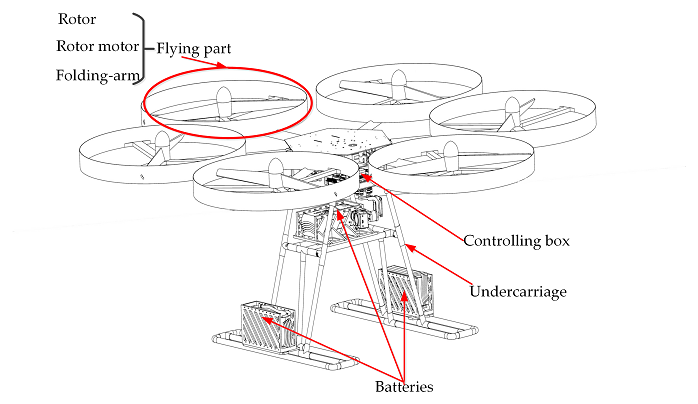
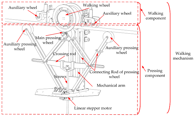
Figure 6 shows the top view of the FPLIR that illustrates the arrangement of the walking wheel, auxiliary wheels, and pressing wheels on the power line.
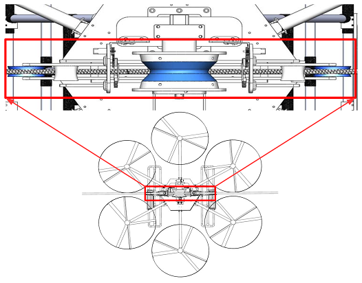
Figure 6The top view of the FPLIR that illustrates the arrangement of the wheels on the power line.
The process of crossing obstacles (e.g., the vibration damper) is shown in Fig. 7. When the obstacle is detected, the linear stepper motor pushes the screw to loosen the crossing rod's and connecting rod's installed pressing wheels away from the power line. When the FPLIR passes through the obstacle, the linear stepper motor pushes the screw to press the crossing rod and the pressing wheels on the power line. The crossing vibration damper should satisfy the following constraints:
where D1 is the distance of two auxiliary pressing wheels, D2 is the distance of two auxiliary wheels, H1 is the distance between the line and the upper side of the pressing wheels, and H2 is the maximum height of the vibration damper under the line.
The whole workflow of the FPLIR is shown in Fig. 8. First, the FPLIR lands online and walks along the power line for inspection. Then, the FPLIR crosses obstacles and continues inspection along the power line. Finally, the FPLIR lands offline when the inspection task is completed. Compared with climbing PLIRs, the FPLIR can quickly land on and off lines and easily cross obstacles. Compared with flying PLIRs, the FPLIR has a longer cruise time and a more stable inspection perspective.
2.2 The dynamics of the walking mechanism
The dynamics models of the walking mechanism are established to analyze the torque of the driving motor and the pressing force. The walking wheel has a middle groove in which sits the power line of radius rc as shown in Fig. 9a, b. The walking wheel is a dual conical portion with an opening angle λ and a minimum radius rmin. The configuration describes the walking wheel steadily hanging on the power line and increases the available traction force because the reaction forces are greater than FN. A simplified dynamics model of the walking mechanism on the power line is illustrated in Fig. 9c. An axis system is built at the O position as shown in Fig. 9c.
The torque equation of the driving motor is expressed as follows:
where r is the effective contact radius of the walking wheel, M is torques of the driving motor, and fr is the driving force.
The balance of forces in the direction of the x axis is obtained as
where fs represents the friction between the walking wheel and line contact, fsi represents the friction between the pressing wheels and line contact, θ represents the climbing slope in degrees, x0 represents the distance of the FPLIR walking along the power line, m123 represents the masses of the FPLIR, and g terms represent the gravitational accelerations.
The fs is expressed as follows:
where FNi is the reaction force and μ is the friction coefficient.
The reaction force FNi is calculated as
The FN is expressed as
The fsi is obtained as
where N1, N2, and N3 represent the pressing forces of the pressing wheels, respectively.
From the parameters of Tables 1 and 2, it can be seen that m123=23.8 kg, λ=30∘, r=0.098 m, and μ=0.3. To analyze the torque of the driving motor, some assumptions can be made for climbing slope in degrees and acceleration, assuming the climbing slope in degrees is 25∘ (θ=25∘) and the linear acceleration is 0 (). The pressing forces are 40 N (main pressing force) and 5 N (auxiliary pressing force), respectively. Finally, the torque of the driving motor can be calculated by Eqs. (2) to (7).
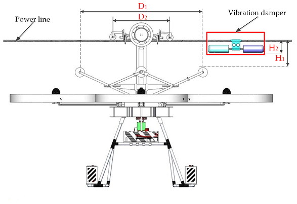
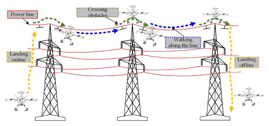
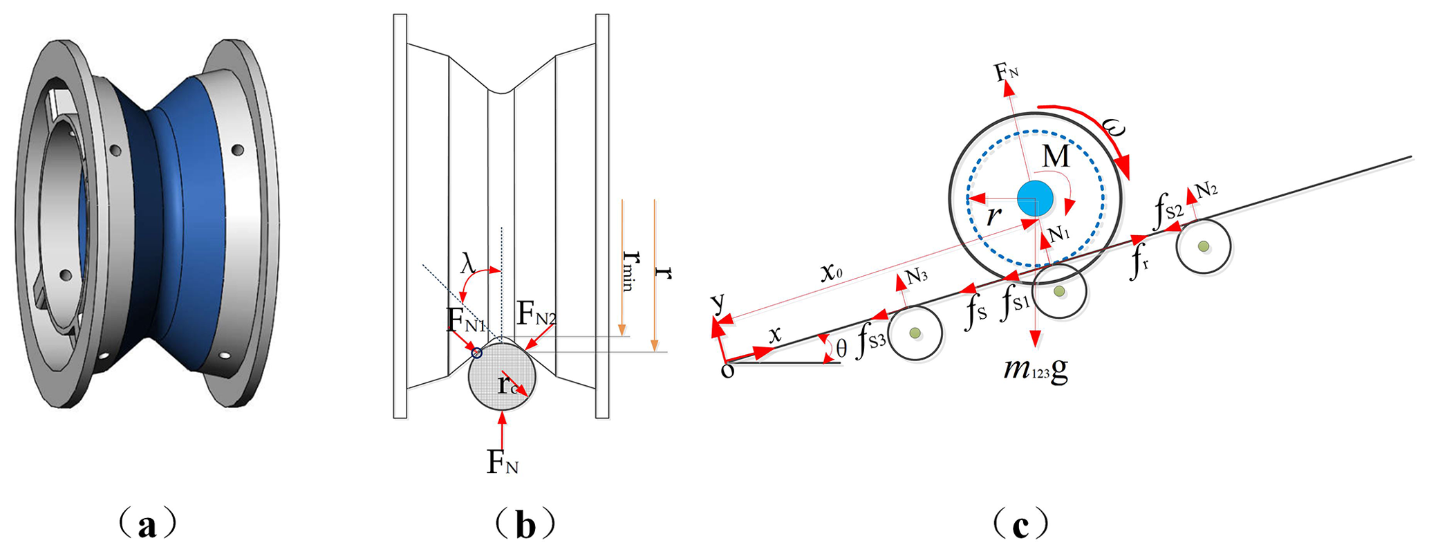
Figure 9Dynamics model of the walking mechanism. (a) The structural design of the FPLIR with the walking wheel. (b) Schematic diagram of the FPLIR walking along the power line. (c) Schematic diagram of the FPLIR moving the whole robot along the power line for the dynamic model.
It was calculated that the maximum torque was enough to effectively perform the climbing slope of the FPLIR. Therefore, the maximum torque of the driving motor is 3.2 N m when the pressing force and climbing slope in degrees are 0. The maximum torque of the driving motor is 3.95 N m when the climbing slope in degrees is 0 and the pressing force is 50 N (the main pressing force is 40 N and the auxiliary pressing force is 10 N). The maximum torque of the driving motor is 7.38 N m when the climbing slope in degrees is 25∘ and the pressing force is 0. The maximum torque of the driving motor is 8.12 N m when the pressing force is 50 N and the climbing slope in degrees is 25∘.
The pressing force varies with the displacement of the screw and the torque of the linear stepper motor. Thus, the dynamics analysis of the pressing component is more necessary as the main load-bearing rod. A simplified dynamics model of the pressing component is shown in Fig. 10a. An axis system is created at the O position, with its x axis pointing in the horizontal direction and its y axis vertical to the x axis in Fig. 10a. The pressing component is symmetric about the y axis in Fig. 10a. Thus, it is analyzed to the right half of the y axis of the pressing component in Fig. 10b to e.
Take the rod O1O2 in Fig. 10a as a fixed rod to reduce the number of unknown forces in the moment equation. The forces are set in the tangential and normal directions in Fig. 10b to e.
The GDE, , and GAE are the gravities of every rod, GA and GC are the gravities of the main pressing wheel and the auxiliary wheel, and F and y are thrust and displacement applied to the screw transforming from the torque of the linear stepper motor. M1 and M2 are the torques of rod O1C and rod AE. The sizes of all unknown forces in Fig. 10b to e are arbitrary, and the actual values are determined by calculated results.
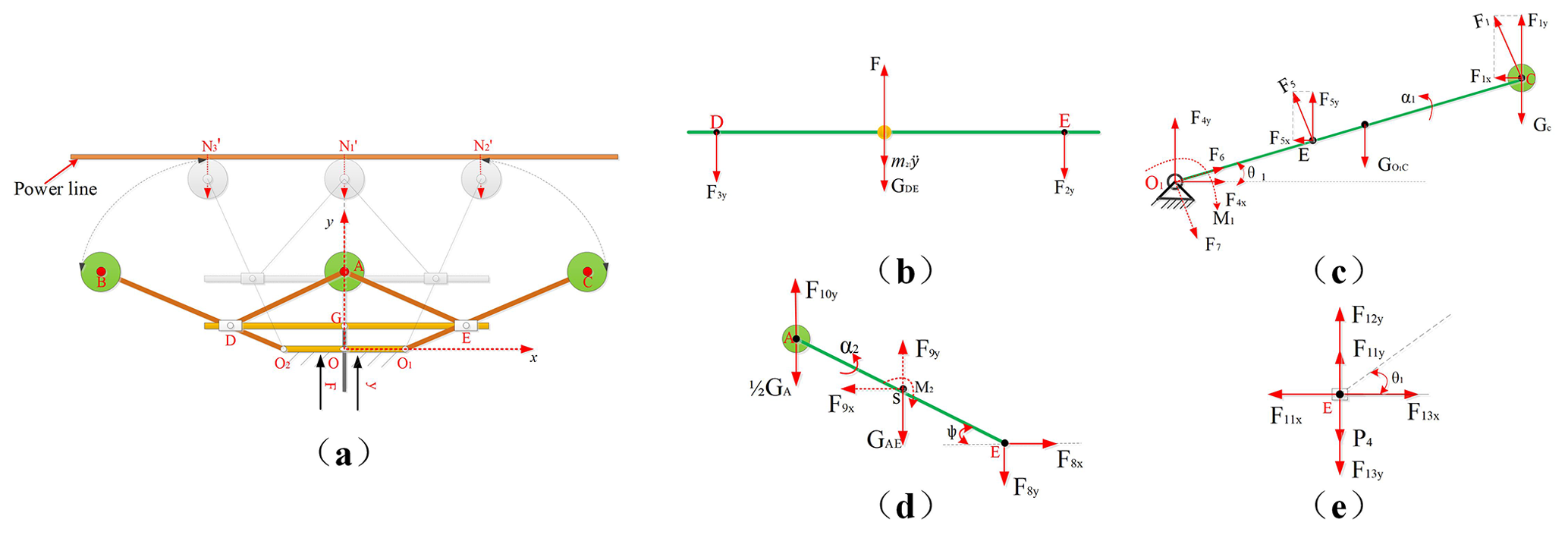
Figure 10Schematic diagram of the pressing component. (a) Dynamics model of the pressing component. (b–e) Force analysis of rods.
Rod AE, rod DE, rod O1C, and point E are separately considered as the research subjects. Assumptions are that the link points have negligible friction and that the center of mass is in the middle position of every rod. The dynamics equations are expressed as follows:
where i, n, Gi, and m2i are the serial number of the rod, the number of one research subject, gravity, and mass, respectively. JOi is the moment of inertia to one link joint. Mi and are load moment and angular acceleration, respectively. Fix is the force of the rod in the horizontal direction (x axis). Fiy is the force of the rod in the vertical direction (y axis), and is the acceleration of the rod mass in the vertical direction. x0, y0 is the coordinate center of the moment, x01, y01 is the coordinate of one end of the rod not being the center of the moment, and xi, yi is the coordinate of the rod mass center. The unknown forces in Fig. 10 can be solved from Eqs. (8) to (10).
The F10y is calculated as follows:
The F1 is calculated as follows:
Equations (11) and (12) are derived from Eqs. (8) to (10). The dynamics model of the pressing component is symmetric about the y axis. Thus, the main pressing force (N1) is 2F10y, and the auxiliary pressing force (N2, N3) is F1cos θ1. It was measured that the maximum angles of θ1 and φ are 43 and 79∘, respectively, to effectively perform the pressing task in Fig. 11a. Finally, the main pressing force and the auxiliary pressing force are 40 N and 5 N, conducted in ADAMS software in Fig. 11b, respectively.
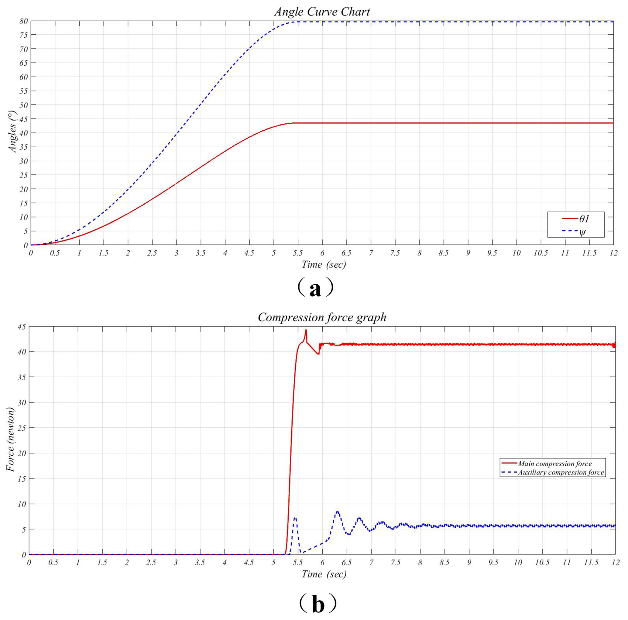
Figure 11The simulation analysis of the pressing force. (a) Maximum angle of the θ1 and the φ. (b) Maximum force of the main pressing force and auxiliary pressing force.
3.1 Generalized wind loads
Figure 12a illustrates the wind loads on the FPLIR and power line model. However, the wind angle α on the FPLIR may not necessarily be perpendicular to the horizontal of the FPLIR. Thus, the schematics of the possible wind angle α are shown in Fig. 12b.
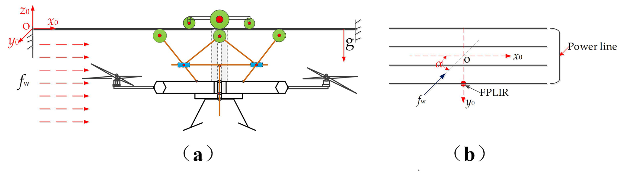
Figure 12(a) The wind loads on the FPLIR and power line model in the x0 direction. (b) Possible wind angle α on the FPLIR.
The dynamics of the wind load fw is expressed as
where Cd is the drag coefficient, A is the cross-sectional area, ρa is the air density, and va is the velocity of the wind.
Cd is a dimensionless quantity used to quantify the resistance of an object in a flow environment (air or liquid) (Qiu et al., 2018; Zhao et al., 2019).
It was seen that α changes from 0 to 90∘. Thus, the general formulation of fw is modified as follows (Alhassan et al., 2019):
where Cd_ix and Aix are the drag coefficient and cross-sectional area of the ith components of the system on the x0 axis, respectively. Cd_iy and Aiy are the drag coefficient and cross-sectional area of the ith components on the y0 axis, respectively. Here, the number of components n is three, including the walking component, the pressing component, and the flying mechanism.
3.2 Coupled dynamics model
The FPLIR–line coupled model under the influence of wind loads is shown in Fig. 13a. The dotted line represents the initial position of the FPLIR (there are no wind loads), and the solid line represents the position of the FPLIR when it is affected by wind in Fig. 13a. The FPLIR walking along the power line can be approximately considered a pendulum when it is affected by wind, leading to the angular displacements of the center of mass (COM) of the FPLIR on the x0 axis (ϕ) and on the y0 axis (β), respectively. The COM position of the FPLIR under the influence of wind loads can be illustrated in Fig. 13b. The horizontal displacement of the COM of the FPLIR is the δ0 along the y0 axis, and the vertical displacement of the COM of the FPLIR is δ1 along the z0 axis in Fig. 13c.
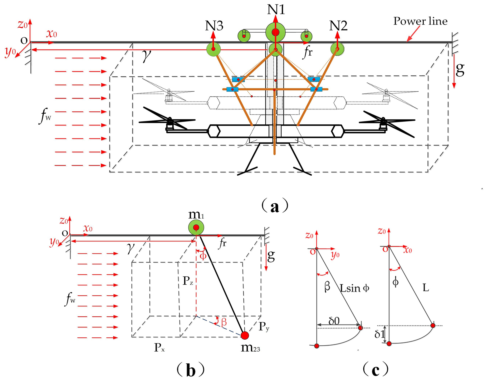
Figure 13(a) Potential wind disturbance on the FPLIR–line coupled system. (b) The schematics of the FPLIR–line model under the influence of wind. (c) The schematics of the FPLIR showing its horizontal swing displacement on the y0 axis (δ0); the schematics of the robot showing its vertical swing displacement on the z0 axis (δ1).
The δ0 can be expressed as
The δ1 is expressed as
where L is the distance between the walking wheel and COM of the FPLIR.
The FPLIR generating the inertial moment J can be expressed as follows:
where m23 is the total mass of the pressing component and flying mechanism.
The general Lagrangian formulation is expressed as
where mi is the mass of the ith coordinates, Qi is the summation of the ith nonconservative forces, and qi is the ith generalized independent point for n number of coordinates. T and U are the total kinetic and potential energies of the dynamics model, respectively. hi is the vertical height from the center of the ith joint to the reference point, O. The total energies T and U are expressed in Eqs. (19) and (20), respectively.
The position Pt of the FPLIR in a 3D plane with reference to the fixed coordinate system O is given as follows:
Therefore, the total kinetic T is calculated as follows:
The potential energy U is calculated as follows:
Moreover, γ is the distance where the FPLIR walks along the power line from a fixed reference point, O(x0, y0, and z0). The external forces Qi of the Lagrangian dynamics of Eq. (18) include the driving force fr, the wind loads fw, the sinusoidal force fb that causes the flexible power line to swing along the y0 axis, and the pressing forces . Thus, the swing angle and swing displacement of the COM of the FPLIR under the influence of wind can be calculated by Eq. (18) using Eqs. (21) to (22).
The acceleration of the FPLIR on the line can be expressed as
The angular acceleration of the FPLIR on the line on the z0 axis can be expressed as
The angular acceleration of the FPLIR on the line on the y0 axis can be expressed as
The δ0 and δ1 are modified by Eqs. (23) to (25). Thus, δ0 and δ1 are expressed as follows:
3.3 Simulation analysis
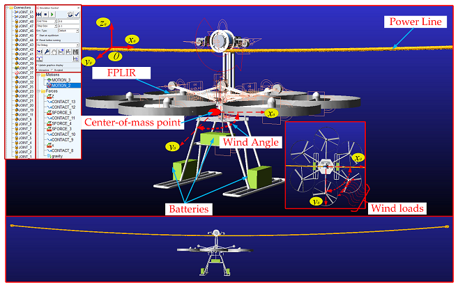
These parameters, including wind speed (15.5 m s−1), wind angle (0 to 90∘), walking speed (0 to 12 m min−1), and pressing force (0 or 48 N), were used to simulate δ0 and δ1 using ADAMS software. Figure 14 illustrates the simulation model of the FPLIR, where the kinematic pairs are added to the simulation model. The screw spiral movement (the screw and the linear stepper motor) is replaced by the moving pair in Fig. 14. In the simulation, the wind loads are loaded at the FPLIR's COM to test the δ0 and δ1. These parameters' used simulation is listed in Table 2, and the swing displacements of the FPLIR's COM (δ0, δ1) are shown in Fig. 15.
The walking speed along the power line is set to 12 m min−1 to study the δ0 and δ1 under the influence of wind angles at 0, 30, 60, and 90∘ on the y0 axis and z0 axis in Fig. 15a, respectively. The maximum value of the δ0 is 5.9 cm when there is no pressing force and the wind angle is 90∘. The maximum value of the δ0 is 3.5 cm when there is a pressing force (48 N) and the wind angle of 90∘ is reduced by 41 %. The δ1 gradually reduces with the gradual increase in wind angle in Fig. 15b, and the maximum value of the δ1 is measured when the wind angle is 0∘.
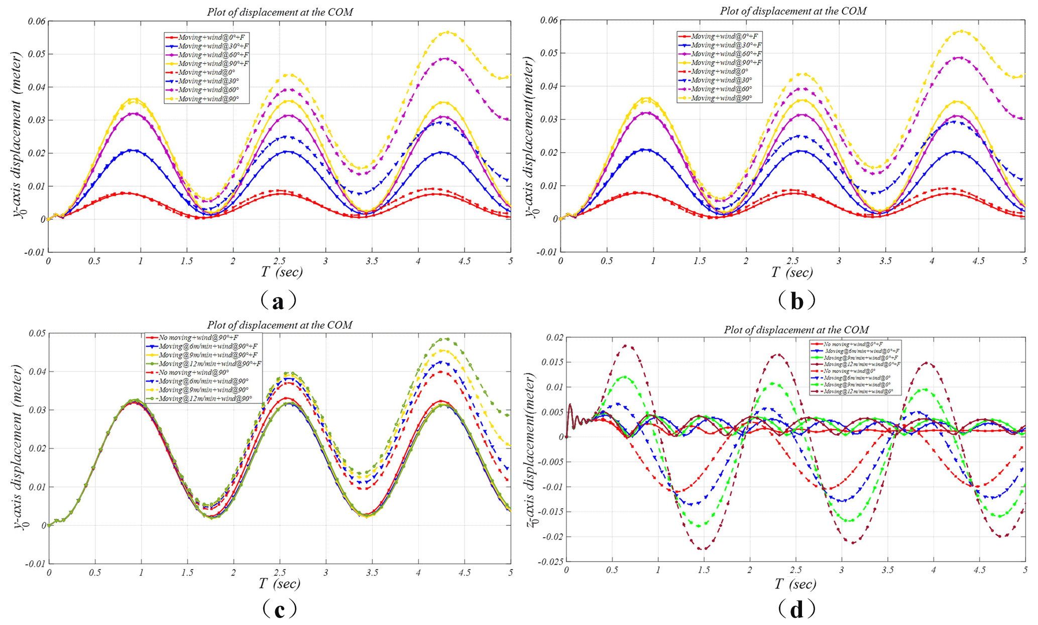
Figure 15Swing displacement of the FPLIR's COM. (a) The swing displacement of the FPLIR's COM (δ0) along the y0 axis at a different wind angle. (b) The swing displacement of the FPLIR's COM (δ1) along the z0 axis at a different wind angle. (c) The swing displacement of the FPLIR's COM (δ0) along the y0 axis at a different walking speed. (d) The swing displacement of the FPLIR's COM (δ1) along the z0 axis at a different walking speed.
These factors influencing the walking stability of the FPLIR are the wind angles of 0 and 90∘ in Fig. 15a and b. Thus, the walking speed along the power line is set (0 to 12 m min−1) to further analyze the walking stability of the FPLIR under the influence of the wind angle at 0∘ and 90∘ on the z0 axis and y0 axis, respectively. The δ0 remains constant, with the walking speed increasing when there is pressing force (48 N) and a wind angle of 90∘, showing that the walking stability under the wind loads is less impacted by the walking speed in Fig. 15c. The maximum value of the δ0 is 3.1 cm in Fig. 15c. The δ1 gradually increases with the gradual increase in the walking speed in Fig. 15d. The maximum value of the δ1 is measured when the walking speed is 12 m min−1.
Moreover, the influence of wind loads on the FPLIR shows that wind load mainly affects the walking stability along the y0 axis (wind angle is 90∘), and the wind load has less impact on the FPLIR along the z0 axis (wind angle is 0∘) in the simulation. The main reasons for the swing displacement of the COM along the z0 axis are analyzed as follows: the FPLIR is affected by inertia in the process of walking along the line, leading to the swing displacement of the COM along the z0 axis gradually increasing. However, the simulation analysis shows that the pressing component can effectively reduce the influence of wind loads on the walking stability of the inspection robot.
An experimental setup is used to verify the walking stability at different wind angles, walking speeds, and pressing forces in moderate gales (wind speed is 15.5 m s−1) in Fig. 16. The following parameters are used for the experimental setup. (1) The length of the power line installed on the frame is 6 m. (2) The FPLIR is 0.8 m above the ground when it is suspended from the power line. (3) The wind angle acting on the COM of the FPLIR is set to change from 0 to 90∘. (4) The mpu6050 gyroscope is installed on the surface of the control box to measure the swing displacement of the COM of the FPLIR on the three axes (x0, y0, and z0). (5) An industrial fan (SF4-2, 1500 W, 2800 r min−1, air volume 11000 m3 h−1) is chosen as the wind source for simulating the moderate gale. (6) The wind speed is measured by a digital anemometer (AC826).
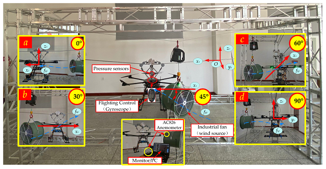
Figure 16The experimental setup. (a) Position of the fan at a 0∘ wind angle. (b) Position of the fan at a 30∘ wind angle. (c) Position of the fan at a 60∘ wind angle. (d) Position of the fan at a 90∘ wind angle.
The walking stability of the FPLIR may be affected by many factors, but three factors (wind angle, walking speed, and pressing force) are selected as the main factors affecting the test according to the previous simulation.
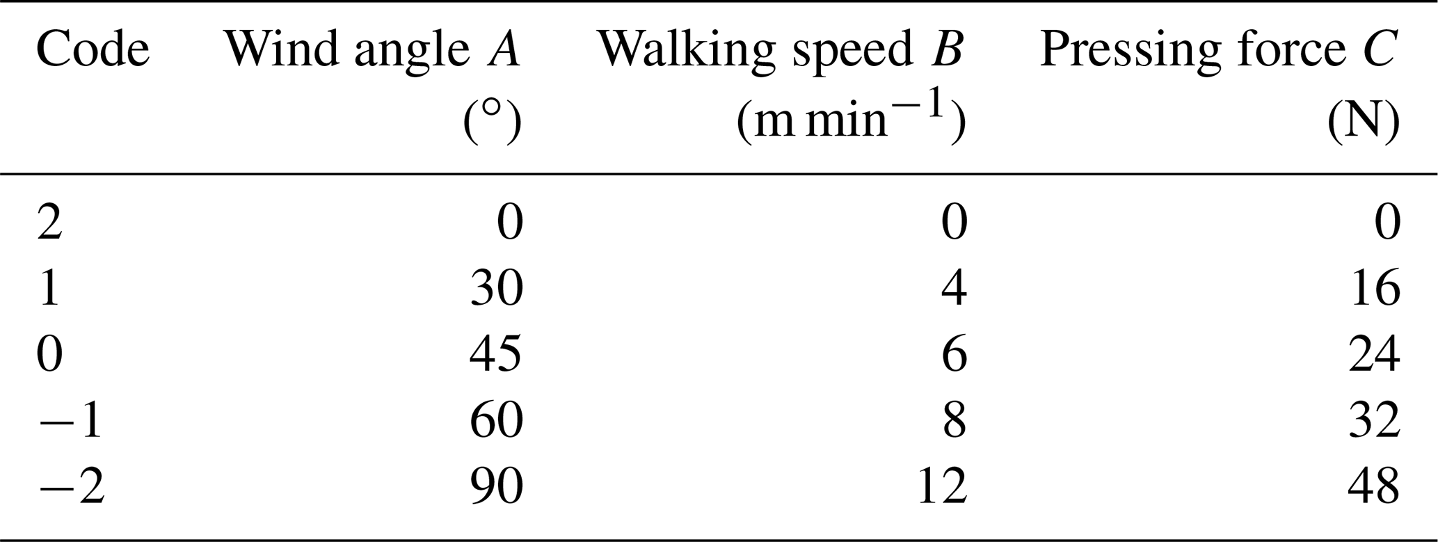
Thus, the walking speed from 0 to 12 m min−1, the pressing force from 0 to 48 N, and the wind angles from 0 to 90∘ are selected to analyze the effects of these factors on the walking stability of the FPLIR adopting an optimized regression design with three factors (wind angle, walking speed, and pressing force) and five levels.
The level and code of variables in the test are listed in Table 3.
Table 3Level and code of variables chosen for central composite design.
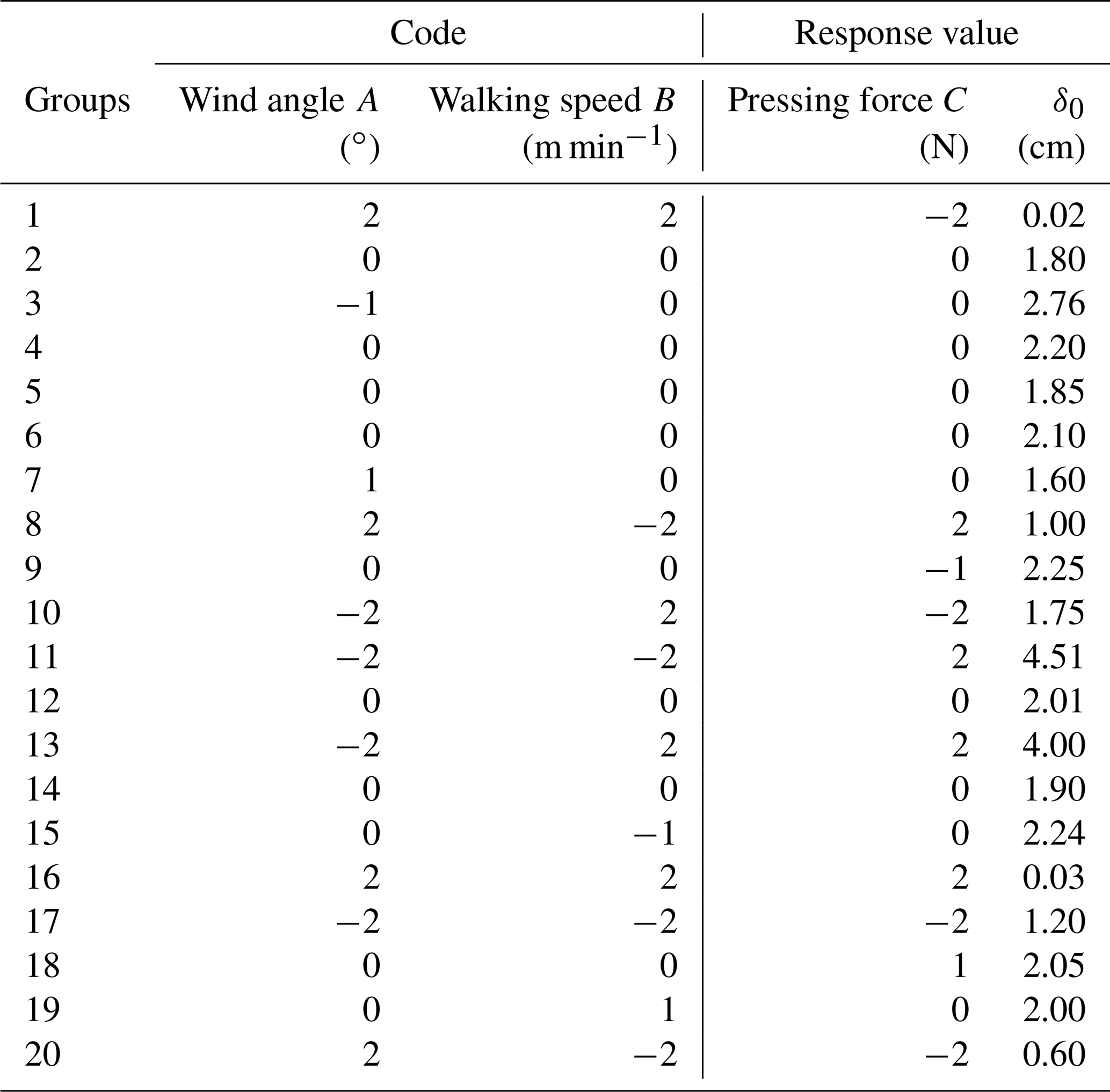
A three-factor, five-level test was designed according to the Box–Behnken test principle, including 20 test points (6 test points were zero estimation errors and the other 14 test points were analysis factors). The test results are listed in Table 4.
The Design-Expert software is used to perform regression analysis to find the optimal parameter combination in the test results. The regression equations between a test index and the factors are obtained, and the analysis of variance is shown in Table 5. The regression equation between the evaluation index and the three factors is derived as follows:
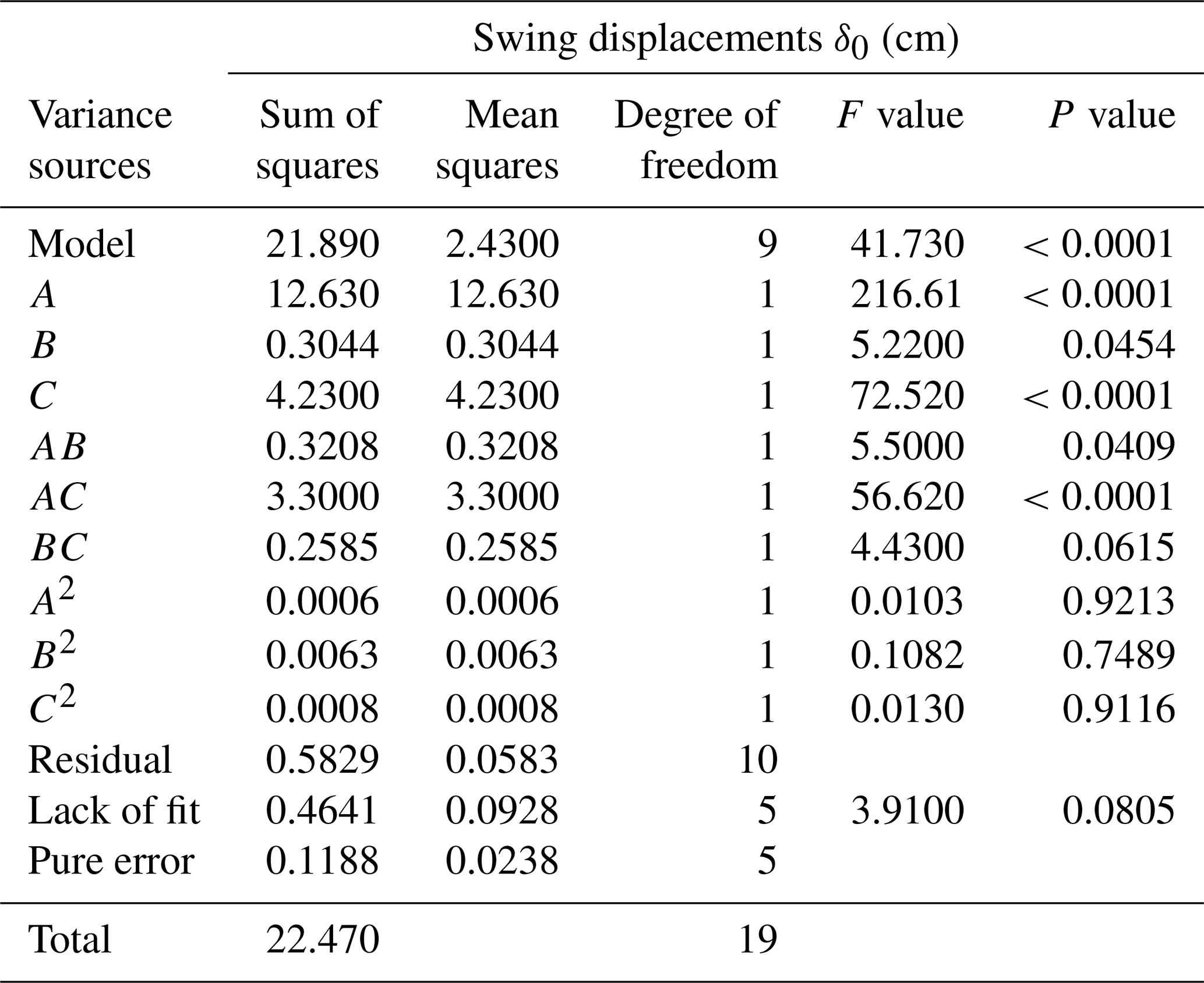
Regression analysis is used to predict the quadratic equation and obtain a prediction model for the response variable δ0. The result shows that the P value (< 0.0001) of the δ0 is less than 0.01 from the analysis of variance (ANOVA) results in Table 5, showing that the regression model is highly significant. The absolute coefficient R2 is 0.9741, demonstrating that the model can meet more than 97 % of the test results. Therefore, the regression model can analyze the parameters related to the influence of the FPLIR under the wind.
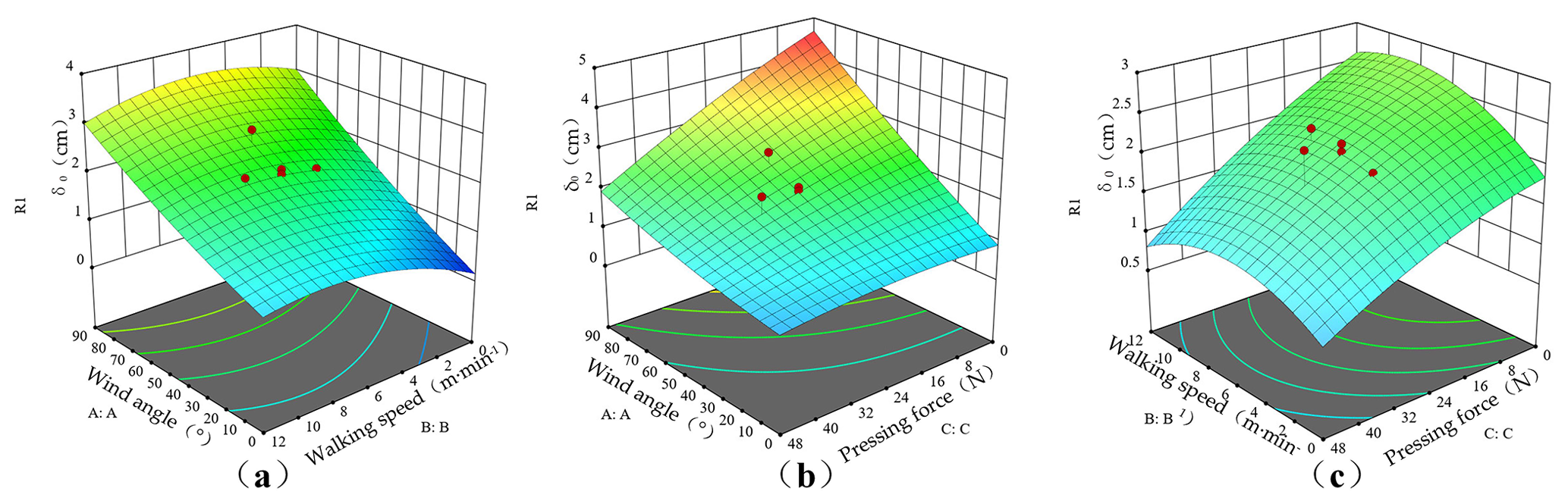
Table 5 shows the monomial coefficient of the δ0, and F values of each factor are ; thus, the influence degree of the factors on the δ0 is wind angle > pressing force > walking speed. The response surface was generated by Design-Expert software to analyze the influence of the interaction factors (wind angle, walking speed, and pressing force) in Fig. 17.
Figure 17a shows the response surface of the interaction between wind angle and walking speed when the pressing force is 24 N. The δ0 gradually increases with increasing wind angle; the δ0 gradually increases and then decreases with the gradually increasing walking speed; the δ0 changes more quickly along the direction of the wind angle than along the direction of the walking speed in Fig. 17a, demonstrating that the influence of the wind angle on the δ0 is more significant than the walking speed at zero levels.
Figure 17b shows the response surface of the interaction between wind angle and pressing force when the walking speed is 6 m min−1. The δ0 gradually decreases with the gradual increase in pressing force. The δ0 is the minimum (when wind angle and walking speed are 0∘ and 48 N, respectively), and the δ0 is the maximum (when wind angle and walking speed are 90∘ and 0 N, respectively). The δ0 changes more quickly along the direction of the wind angle than along the direction of the pressing force in Fig. 17b, showing that the influence of the wind angle on the δ0 is more significant than the pressing force at zero levels.
Figure 17c shows the response surface of the interaction between walking speed and pressing force when the wind angle is 45∘. The δ0 changes more quickly along the direction of the pressing force than along the direction of the walking force in Fig. 17c, showing that the influence of the pressing force on the δ0 is more significant than the walking speed at zero levels.
It is necessary to further verify the impact of the three factors (wind angle, pressing force, and walking speed) on the walking stability of the FPLIR using Design-Expert to optimize and analyze the three factors and to get the maximum and minimum values of the δ0 when the FPLIR is affected by wind loads. The optimization results of the three factors are as follows. (1) The maximum value of δ0 is 4.7 cm (when wind angle, walking speed, and pressing force are 90∘, 7.2 m min−1, and 0, respectively). (2) The minimum value of δ0 is 0 (when wind angle, walking speed, and pressing force are 0∘, 0 m min−1, and 3.4 N, respectively). (3) The maximum value of the δ0 is 2.5 cm when pressing force increases to 39.4 N, reduced by 46.2 % (when wind angle and walking speed are 90∘ and 5.1 m min−1, respectively), which effectively reduces the influence of wind loads and improves the stability of the FPLIR.
The conclusions of this paper can be summarized as follows.
-
We propose a novel FPLIR with the ability to fly and walk, including a flying mechanism and a walking mechanism. The overall size of the FPLIR is 1250 mm × 1250 mm × 1200 mm, and the total weight is about 24 kg.
-
The dynamics model of the FPLIR on the power line using the Lagrangian equation is derived to analyze walking stability caused by wind, considering pressing force and walking speed.
-
In the simulation, the influence of wind on the walking stability of the FPLIR is studied to show that the wind angle of 90∘ has the greatest influence on the walking stability. The δ0 can be reduced by 41 % when using the pressing component, demonstrating that the directing-push pressing component effectively improves the walking instability of the FPLIR under the wind.
-
A three-factor, five-level test was designed to establish a response surface model with wind angle (0 to 90∘), walking speed (0 to 12 m min−1), and pressing force (0 to 48 N). The test results show that wind angle and pressing force have a significant influence (P<0.05) on the walking stability. The maximum value of δ0 is 4.7 cm (when wind angle, walking speed, and pressing force are 90∘, 7.2 m min−1, and 0, respectively). The maximum value of δ0 is 2.5 cm when the pressing force increasing to 39.4 N is reduced by 46.2 % (when wind angle and walking speed are 90∘ and 5.1 m min−1, respectively).
Therefore, it is proved that the FPLIR has been successfully designed and can be applied for power line inspection, providing a theoretical basis for slipping control, collecting images of intelligence inspection robots in the future.
All the data used to support the findings of this study are included in the relevant figures and tables in the article.
XQ proposed and developed the research design and advised on the experimental method. BJ collected experimental data, performed the data analysis, interpreted the results, and wrote the manuscript. JL assisted with advising on the experimental method, refining the manuscript, and coordinating the revision. JZ assisted with results interpretation. HL, BL, and ZL assisted with processing experiments.
The contact author has declared that neither they nor their co-authors have any competing interests.
Publisher's note: Copernicus Publications remains neutral with regard to jurisdictional claims in published maps and institutional affiliations.
The authors would like to thank anonymous reviewers for their valuable comments and suggestions that enabled us to revise the paper.
This study was supported by the National Natural Science Foundation of China (grant nos. 62063030 and 62163032), the Financial Science and Technology Program of the XPCC (grant no. 2021DB003), and the High-level Talent Project of Shihezi University (grant nos. RCZK2018C31 and RCZK2018C32).
This paper was edited by Zi Bin and reviewed by two anonymous referees.
Abd-Elaal, E.-S., Mills, J. E., and Xing, M.: A review of transmission line systems under downburst wind loads, J. Wind. Eng. Ind. Aerod., 197, 503–513, https://doi.org/10.1016/j.jweia.2018.07.004, 2018.
Alhassan, A. B., Zhang, X., Shen, H., Jian, G., Xu, H., and Hamza, K.: Investigation of Aerodynamic Stability of a Lightweight Dual-Arm Power Transmission Line Inspection Robot under the Influence of Wind, Math. Probl. Eng., 2019, 1–16, https://doi.org/10.1155/2019/2139462, 2019.
Browne, N. W. and Adam, J. F.: The construction of lines using helicopters, Overhead Line Design and Construction: Theory and Practice, 1989, International Conference, 28 December 1998, 202–206, 1988.
Buskey, G., Wyeth, G., and Roberts, J.: Autonomous helicopter hover using an artificial neural network, IEEE International Conference on Robotics & Automation, 21–26 May 2001, Seoul, Korea, 1635–1640, https://doi.org/10.1109/ROBOT.2001.932845, 2001.
Chang, W., Yang, G., Yu, J., Liang, Z., and Chao, Z.: Development of a power line inspection robot with hybrid operation modes, 2017 IEEE/RSJ International Conference on Intelligent Robots and Systems, 24–28 September 2017, Vancouver, BC, Canada, 937–978, https://doi.org/10.1109/IROS.2017.8202263, 2017.
Debenest, P. and Guarnieri, M.: Expliner – From prototype towards a practical robot for inspection of high-voltage lines, International Conference on Applied Robotics for the Power Industry, 5–7 October 2010, Montreal, QC, Canada, 1–6, https://doi.org/10.1109/CARPI.2010.5624434, 2010.
Eisenbeiss, H.: A mini unmanned aerial vehicle (UAV): system overview and image acquisition, International Workshop on Processing & Visualization Using High Resolution Imagery, 18–20 November 2009, Pitsanulok, Thailand, 1–7, 2009.
Fan, F., Wu, G., Wang, M., Cao, Q., and Yang, S.: Multi-Robot Cyber Physical System for Sensing Environmental Variables of Transmission Line, Sensors (Basel), 18, 1–29, https://doi.org/10.3390/s18093146, 2018.
Fonseca, A., Abdo, R., and Alberto, J.: Expliner – Robot for Inspection of Transmission Lines, IEEJ Transactions on Power & Energy, 130, 3978–3984, https://doi.org/10.1109/ROBOT.2008.4543822, 2008.
Hrabar, S., Merz, T., and Frousheger, D.: Development of an autonomous helicopter for aerial powerline inspections, International Conference on Applied Robotics for the Power Industry, 5–7 October 2010, Montreal, QC, Canada, 9 November 2010, 1–6, https://doi.org/10.1109/CARPI.2010.5624432, 2010.
Jalal, M., Sahari, K., Anuar, A., Arshad, A., and Idris, M. S.: Conceptual design for transmission line inspection robot, 4th International Conference on Energy and Environment 2013 (ICEE 2013), 2013 IOP Conf. Ser., Earth Environ. Sci., 16, 012094, https://doi.org/10.1088/1755-1315/16/1/012094, 2013.
Jiang, B., Hui, X., Zhao, X., and Min, T.: A Novel Monocular-Based Navigation Approach for UAV Autonomous Transmission-Line Inspection, 2018 IEEE/RSJ International Conference on Intelligent Robots and Systems (IROS), 1–7, https://doi.org/10.1109/IROS.2018.8593926, 2018.
Jones, D. I.: Aerial inspection of overhead power lines using video: estimation of image blurring due to vehicle and camera motion, IEE Proceedings – Vision, Image and Signal Processing, 147, 157–166, https://doi.org/10.1049/ip-vis:20000226, 2000.
Karjalainen, M., Ahokas, E., Hyyppa, J., Matikainen, L., and Anttoni, J.: Remote sensing methods for power line corridor surveys, ISPRS J. Photogramm. Remote Sens., 119, 10–31, https://doi.org/10.1016/j.isprsjprs.2016.04.011, 2016.
Katrašnik, J., Pernus, F., and Likar, B.: A Climbing-Flying Robot for Power Line Inspection, Climbing and Walking Robots, 2008, 96–97, https://doi.org/10.5772/8840, 2010.
Li, H., Wang, B., Liang, L., Tian, G., and Zhang, J.: The design and application of SmartCopter: An unmanned helicopter based robot for transmission line inspection, 2013 Chinese Automation Congress (CAC), 7–8 November 2013, Changsha, China, 697–702, https://doi.org/10.1109/CAC.2013.6775842, 2013.
Lima II, E. J., Souza Bomfim, M. H., and de Miranda Mourão, M. A.: POLIBOT – POwer Lines Inspection RoBOT, Ind. Robot, 45, 98–109, https://doi.org/10.1108/IR-08-2016-0217, 2018.
Liu, B., Liu, M., Liu, X., Tuo, X., Wang, X., Zhao, S., and Xiao, T.: Design and Realize a Snake-Like Robot in Complex Environment, J. Robotics, 2019, 1–9, https://doi.org/10.1155/2019/1523493, 2019.
Luo, S. M. and Tian, L.: Development of automatic line-tracking inspection device for high voltage transmission lines based on ground control, 2011 IEEE International Conference on Computer Science and Automation Engineering, 10–12 June 2011, IEEE, 2011 IEEE International Conference on Computer Science and Automation Engineering, 422–426, https://doi.org/10.1109/CSAE.2011.5952711, 2011.
Luque-Vega, L. F., Castillo-Toledo, B., Loukianov, A., and Gonzalez-Jimenez, L. E.: Power line inspection via an unmanned aerial system based on the quadrotor helicopter, MELECON 2014–2014 17th IEEE Mediterranean Electrotechnical Conference, 13–16 April 2014, Beirut, Lebanon, 393–397, https://doi.org/10.1109/MELCON.2014.6820566, 2014.
Menendez, O., Cheein, F. A., Perez, M., and Kouro, S.: Robotics in Power Systems: Enabling a More Reliable and Safe Grid, IEEE Industrial Electronics Magazine, 11, 22–34, https://doi.org/10.1109/MIE.2017.2686458, 2017.
Miralles, F., Hamelin, P., Lambert, G., Lavoie, S., and Montambault, S.: LineDrone Technology: Landing an Unmanned Aerial Vehicle on a Power Line, 2018 IEEE International Conference on Robotics and Automation (ICRA), 21–25 May 2018, Brisbane, QLD, Australia, 6545–6552, https://doi.org/10.1109/ICRA.2018.8461250, 2018.
Montambault, S. and Pouliot, N.: Hydro-Québec's Power Line Robotics Program: 15 years of development, implementation and partnerships, International Conference on Applied Robotics for the Power Industry, 14–16 October 2014, Foz do Iguacu, Brazil, 1–6, https://doi.org/10.1109/CARPI.2014.7030065, 2015.
Pelacchi, P.: Automatic hot line insulator washing device positioned by helicopter, IEEE International Conference on Transmission & Distribution Construction, Operation & Live-Line Maintenance Proceedings, May 1998, 133 pp., https://doi.org/10.1109/TDCLLM.1998.668343, 1998.
Pouliot, N. and Montambault, S.: Field-oriented developments for LineScout Technology and its deployment on large water crossing transmission lines, J. Field Robot., 29, 25–46, 2012.
Qin, X., Wu, G., Lei, J., Fan, F., Ye, X., and Mei, Q.: A Novel Method of Autonomous Inspection for Transmission Line based on Cable Inspection Robot LiDAR Data, Sensors, 18, 596, https://doi.org/10.3390/s18020596, 2018.
Qiu, R., Miao, X., Zhuang, S., Hao, J., and Jing, C.: Design and implementation of an autonomous landing control system of unmanned aerial vehicle for power line inspection, 2017 Chinese Automation Congress (CAC), 20–22 October 2017, Jinan, China, 7428–7431, https://doi.org/10.1109/CAC.2017.8244120, 2018.
Seok, K. H. and Kim, Y. S.: A State of the Art of Power Transmission Line Maintenance Robots, J. Electr. Eng. Technol., 11, 1412–1422, 2016.
Shruthi, C. M., Sudheer, A. P., and Joy, M. L.: Dual arm electrical transmission line robot: motion through straight and jumper cable, Automatika, 60, 207–226, https://doi.org/10.1080/00051144.2019.1609256, 2019.
Tao, G. and Fang, L.: A multi-unit serial inspection robot for power transmission lines, Ind. Robot, 46, 223–234, https://doi.org/10.1108/IR-09-2018-0195, 2019.
Tao, G., Fang, L., and Lin, X.: Optimization design of the multi-unit serial inspection robot for power transmission line, 2016 4th International Conference on Applied Robotics for the Power Industry (CARPI), 1–6, https://doi.org/10.1109/CARPI.2016.7745637, 2016.
Wang, B., Lei, H., Zhang, H., Qian, W., and Li, B.: A Flying Robotic System for Power Line Corridor Inspection, IEEE International Conference on Robotics & Biomimetics, 19–23 December 2009, Guilin, China, 2468–2473, https://doi.org/10.1109/ROBIO.2009.5420421, 2009.
Wang, B., Chen, X., Qian, W., Liang, L., and Li, B.: Power line inspection with a flying robot, International Conference on Applied Robotics for the Power Industry, 5–7 October 2010, Montreal, QC, Canada, 1–6, https://doi.org/10.1109/CARPI.2010.5624430, 2010.
Wang, L., Fei, L., Xu, S., Zhen, W., Sheng, C., and Zhang, J.: Design, Modeling and Control of a Biped Line-Walking Robot, Int. J. Adv. Robot. Syst., 2011, 5863–5868, https://doi.org/10.5772/10498, 2011a.
Wang, L., Fei, L., Zhen, W., Xu, S., Zhang, J., and Sheng, C.: Analysis and control of a biped line-walking robot for inspection of power transmission lines, IEEE International Conference on Robotics & Automation, 9–13 May 2011, Shanghai, 39–47, https://doi.org/10.5772/10498, 2011b.
Wei, W., Yu-Cheng, B., Gong-Ping, W., Shui-Xia, L., and Qian, C.: The Mechanism of a Snake-Like Robot's Clamping Obstacle Navigation on High Voltage Transmission Lines, Int. J. Adv. Robot. Syst., 10, 1–14, https://doi.org/10.5772/56767, 2013.
Whitworth, C. C., Duller, A., Jones, D. I., and Earp, G. K.: Aerial video inspection of overhead power lines, Power Eng. J., 15, 25–32, https://doi.org/10.1049/pe:20010103, 2001.
Xie, Y., Huang, L., Wang, D., Ding, H., and Yin, X.: Modeling and Analysis of Progressive Ice Shedding along a Transmission Line during Thermal De-Icing, Math. Problem. Eng., 2019, 1–12, https://doi.org/10.1155/2019/4851235, 2019.
Yan, G., Wang, J., Qiang, L., Lin, S., and Xiao, Z.: An airborne multi-angle power line inspection system, IEEE Int. Geosci. Remote Sens. Symp., Barcelona, 2008, 2913–2915, https://doi.org/10.1109/IGARSS.2007.4423453, 2008.
Yang, D., Feng, Z., Ren, X., and Lu, N.: A novel power line inspection robot with dual-parallelogram architecture and its vibration suppression control, Adv. Robotics, 28, 807–819, https://doi.org/10.1080/01691864.2014.884936, 2014.
Yang, L., Fan, J., Liu, Y., Li, E., and Liang, Z.: A Review on State-of-the-Art Power Line Inspection Techniques, IEEE Trans. Instrum. Meas., 69, 9350–9365, https://doi.org/10.1109/TIM.2020.3031194, 2020.
Yu, P., Yang, J., and Liu, L.: Design and implementation of self-balancing control scheme for flying-slipping patrol robot, Electr. Meas. Instrum., 52, 91–95, 2015.
Zhang, J., Liang, L., Wang, B., Chen, X., and Zheng, T.: High Speed Automatic Power Line Detection and Tracking for a UAV-Based Inspection, International Conference on Industrial Control & Electronics Engineering, 23–25 August 2012, Xi'an, China, 266–269, https://doi.org/10.1109/ICICEE.2012.77 2012.
Zhao, L., Huang, X., Zhang, Y., Tian, Y., and Zhao, Y.: A Vibration-Based Structural Health Monitoring System for Transmission Line Towers, Electronics, 8, 1–11, https://doi.org/10.3390/electronics8050515, 2019.
- Abstract
- Introduction
- Mechanical structure design and dynamics of the walking mechanism
- Mechanism of wind loads on the FPLIR
- The experiment
- Experimental results and discussion
- Conclusions
- Data availability
- Author contributions
- Competing interests
- Disclaimer
- Acknowledgements
- Financial support
- Review statement
- References