the Creative Commons Attribution 4.0 License.
the Creative Commons Attribution 4.0 License.
Kinematic and dynamic accuracy of spherical mechanisms
Sergey Kheylo
Van Quoc Nguyen
Among parallel robots, spherical robots occupy an important place. Most applications of spherical manipulators can be found in orienting devices, such as camera orienting and medical instrument alignment. A spherical parallel robot is, in general, made up of the base platform and the moving platform. This mobile platform and base are connected by three equally spaced legs, each consisting of revolute joints only. The axes of all joints intersect at a common point, which is called the center of rotation. The motion of the moving platform is confined on the surface of a sphere centered at the rotation center. A spherical parallel robot provides 3 degrees of freedom of pure rotations. These robots have been the subject of many papers dealing with the structure, the problems of position and velocity, workspace modeling, singularity analysis, and some problems with the dynamic analysis. However, not all the important problems have been solved. These concern the problem of accuracy. This paper presents accuracy of the spherical parallel. In the considered spherical manipulator, each leg consists of five kinematic pairs. The kinematic accuracy is determined on the kinematic problem. The dynamic accuracy is estimated on the equation of motion. Examples of solving the problem of determining the positioning error of the output level are presented.
- Article
(1953 KB) - Full-text XML
- BibTeX
- EndNote
Production automation is ensured by the use of robotic complexes and systems. One of the important characteristics of assessing the quality of functioning of robotic systems is the positioning accuracy. The task of ensuring this accuracy should be solved at the design stage of machinery and equipment.
Most of the production of light industry requires laser cutting and surface treatment, welding, and medical robotics.
The positioning error of the output link, when it is repeatedly withdrawn to a given point, is expressed for a spherical mechanism in angular units. The positioning error is determined by systematic (inaccuracy of the control system and deviations from the nominal dimensions of the links) and random components (gaps in the joints, loosening in fasteners, temperature fluctuations, robot vibrations caused by adjacent equipment, residual vibrations, and fatigue deformations of links). The positioning accuracy is determined by the positioning error of the output link (capture) when it is repeatedly brought to a given point and is expressed in angular or linear dimensions.
Systematic errors can be partially or completely compensated. Reducing random errors should be considered in design and operation. Most robotic systems consist of spatial mechanisms, including mechanisms of a parallel structure (Merlet, 2000; Kong and Gosselin, 2007; Gogu, 2008). Modern control systems allow for the introduction of appropriate amendments. Also, the negative impact of vibrations at the base of the robot on the positioning accuracy can be reduced by organizational measures (i.e., coordination of the manipulation cycle with the cycle of the equipment that caused the vibration). The purpose of cycle matching is to establish the time interval between the impact and the final stage of the manipulation cycle. This allows vibrations to dim before the positioning is complete. Residual oscillations of the output link, resulting from insufficient rigidity of the link drives and instability of the control system, have a significant effect on accuracy. The nature of the residual vibrations depends on the dynamic properties of the manipulator.
When creating robots, they strive to perform links with a uniform, constant cross section along the length. In this case, there is no need to describe the links through the distribution of length over mass, moments of inertia, and stiffness. In this case, the task of dynamic accuracy is simplified, since, in this case, the Lagrangian equations describe mechanical systems with lumped parameters.
In most cases, the positioning error is determined from solving problems on the position of the mechanism. However, this approach is not universal, since inaccuracies in the manufacture of links of mechanisms are inevitable, the temperature of the working environment is not constant, the mechanism can be located on a moving base, external influences can be present, and instability of motion occurs at a given law of motion.
An interesting approach is one that takes into account the determination of the accuracy of finding the executive body while taking into account the above restrictions and the possibility of their compensation. The paper shows a sequential approach to determining the kinematic, then dynamic, accuracy of the executive body and the positioning errors during control. Thus, an integrated approach to assessing the performance of the actuator is presented.
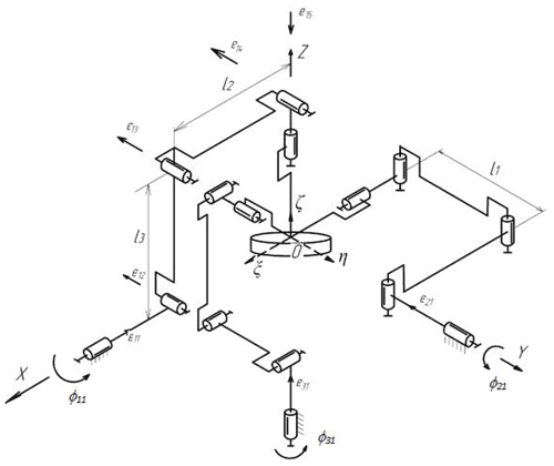
The article presents a solution to the problem of determining the positioning error of the working body, using the example of a spherical manipulator with 3 degrees of freedom of a parallel structure (Fig. 1). Such manipulators are used in orienting devices, in test benches, medical robotic complexes, for processing spherical surfaces, in mixers, and for performing rotational movements (Huda and Takeda, 2007; Mianovski, 2007; Leguay-Durand and Reboulet, 1997; Bai et al., 2016; Chaker et al., 2011; Nosova et al., 2018). The paper considers a spherical manipulator with 3 degrees of freedom and investigates the issues of the kinematic and dynamic accuracy of the positioning of the executive body.
In the considered mechanism, each input chain link is connected to a rotary motor. The output link is a platform rotating at point O around three coordinate axes. The output coordinates are the angles of rotation of the platform, with the angle α of rotation around the x axis, the angle β of rotation around the y axis, and the angle γ of rotation around the z axis. The generalized coordinates are the angles ϕ11, ϕ21, and ϕ31 of rotation of the input links, respectively, of the first kinematic chain and second and third kinematic chain.
The solution to the positioning problem determines the relationship between the input and output coordinates and is presented in the following form (Kheylo and Glazunov, 2016; Nhan et al., 2019):
In general, the positioning problem is specified in the form of implicit functions, as follows:
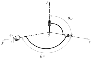
where θi1, θi2 is the angle between the axes of the kinematic pairs (Fig. 2).
The total differential of function (2) is written as follows:
According to the linear accuracy theory, the increment in the drives is zero, where .
The implicit function equations can be written as follows (Kheylo and Glazunov, 2014):
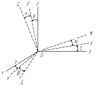
In the considered mechanism, the angles between the axes of the kinematic pairs θi1, θi2 are not equal to 90∘. The sequence of rotations of the output link from a movable coordinate system to a fixed one is shown in Fig. 3.
The transition matrix, from a moving coordinate system to a fixed one, will have the following form:
where, in the following:
which are the rotation matrices of the first kinematic pairs and second and third kinematic pairs around the movable axis z by the angles φ11, φ12, and φ13, respectively.
which are the matrices of rotations around the x and y axes by the angles θ11 and θ12, respectively. θ11 and θ12 are the angles between the adjacent pairs.
which are matrices of additional rotations for aligning the moving and stationary coordinate system around the z and x axes by tje angles ξ11, and ξ12, respectively, with ξ11=90∘, and ξ12=90∘.
The unit vector of the axis of the pair of the output links of the first chain has the following coordinates: which are substituted into the following constraint equation . Using the found values of the matrices A and B′, we obtain the following equation:
For the second kinematic chain, the transition matrix from a moving coordinate system to a fixed one will have the following form:
where, in the following:
which are rotation matrices of the first kinematic pairs and second and third kinematic pairs around the movable axis x by the angles φ21, φ22, and φ23, respectively.
which are matrices of rotations around the z, y axes by the angles θ22 and θ21, respectively, and θ21 and θ22 are the angles between adjacent pairs.
which are matrices of additional rotations for aligning the moving and stationary coordinate systems around the z and x axes by the angles ξ22 and ξ21, respectively, with ξ21=90∘ and ξ22=90∘.
For the third kinematic chain, the transition matrix from a moving coordinate system to a fixed one will have the following form:
which are matrices of rotations of the first kinematic pairs and second and third kinematic pairs around the movable axis y by the angles φ31, φ32, and φ33, respectively.
which are matrices of rotations around the z and x axes by the angles θ31 and θ32, respectively. θ31 and θ32 are the angles between adjacent pairs.
which are matrices of additional rotations for aligning the moving and stationary coordinate systems around the z and x axes by the angles ξ31 and ξ32, respectively, with ξ31=90∘ and ξ32=90∘.
Position function F1 will look as follows:
Partial derivatives will be equal to the following:
The values of the remaining partial derivatives are known from solving the positioning problem. Let us determine the positioning error of the output link in different positions with deviations of the angles between the axes equal to and .
The deviations of the angles of the output link are expressed, from Eq. (4), as follows:
where, in the following:
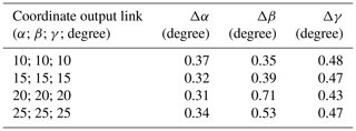
Thus, the solution to the problem of determining the deviation of the actuator of the mechanism in the case of the inaccuracy of its manufacture is presented. The values of the deviation of the coordinates of the output link at a given deviation between the axes are presented in Table 1.
When assessing the dynamic positioning accuracy of the grip, small fluctuations around the stable equilibrium position are investigated.
The equations of motion for a manipulator with 3 degrees of freedom will be described by a system of differential equations (Kheylo and Glazunov, 2014; Nhan et al., 2019) as follows:
where T is the kinetic energy of the system, and Π is potential energy of the system.
The potential energy of the system is defined as follows:
where ci is the chain stiffness.
Kinetic energy is a quadratic function of generalized velocities.
where ωx, ωy, and ωz are the angular velocities of the output link around the x, y, and z axes, respectively. and are the moments of inertia of the output link around the axes x, y, and z, respectively. m is the mass of the output link (we take m=0.5 kg, and r=0.1 m). r is the radius of the platform of the output link. Then, Eq. (6) takes the following form:
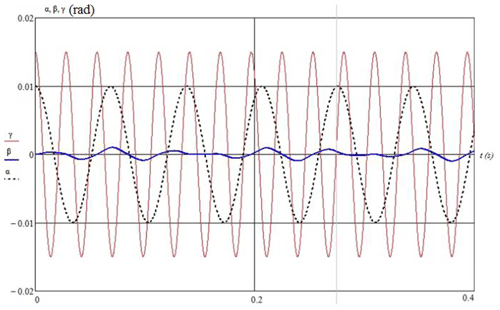
The problem of determining the deviation of the coordinates of the input link when removing it from the equilibrium position is solved numerically (Fig. 4). Reducing the dynamic error can be achieved by increasing the rigidity of the drive or by introducing damping devices.
Automatic compensation of movements, using digital or pulse controllers, is also an effective method of damping the vibrations.
The reduction of residual vibrations is possible by increasing the stiffness of the drives. This must also be taken into account when constructing a control algorithm (Nhan et al., 2019).
Let us set the required movement of the output link in the form of the law of coordinate change, i.e., αT(t), βT(t), and γT(t). The required speeds are , , and , and acceleration is , , and , which we obtain after the differentiation.
The control problem is to minimize the coordinate error is as follows: , , , with the speed of , , and , and acceleration of , , and , where α(t), β(t), and γ(t) are the actual values of the coordinates of the output link.
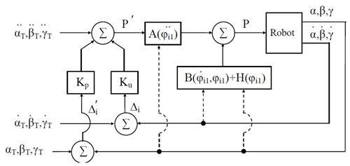
We then simulate the movement of the output link of the parallel structure mechanism along a given trajectory using the developed algorithm for optimal motion control (Fig. 5).
To measure the magnitude of the deviations, we use a quadratic integral assessment as follows:
There must be the following:
We then rewrite Eq. (8) in a form appropriate to the oscillatory link, as follows:
where τ is time, and ζ is the damping ratio.
The law of acceleration change corresponds to the oscillatory link as follows:
The equation of motion for a spherical mechanism with 3 degrees of freedom has the following form:
where are the moments of inertia about the axes ξ, η, and ζ. and M3 are the moments in drives. are the variable coefficients.
, , , , , and are the projection of accelerations and velocities on the moving axes of ξ, η, and ζ.
The dynamic properties of the system are determined by transient processes. Transient processes (the overshoot time and deviations of the output link from a given trajectory) are regulated by feedback coefficients γ0 and γ1.
Let us set the law of motion of the executive link, as follows:
The differential acceleration in Eq. (9) takes the following form:
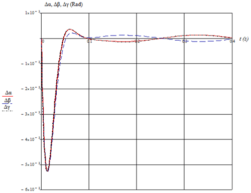
When moving with feedback, the graph of the changes in the position error and the torque in the drive is shown in Fig. 6.
Thus, by changing the feedback coefficients, it is possible to regulate the deviations of the output link from the desired trajectory, while the overshoot time τ changes.
An integrated approach allows one to evaluate and determine the positioning error of the output link from the standpoint of kinematics, dynamics, and control. This approach will allow, when synthesizing mechanisms, us to propose approaches to compensate for or completely eliminate errors.
So, with the kinematic estimate, the proposed approach to assessing the kinematic accuracy allows one to determine the deviations in the output link using the theory of accuracy. This allows one to determine the deviations in the output link at any point in the working area and propose constructive solutions for its compensation. This approach to determining the positioning error makes it possible to calculate the deviations in the output link for similar mechanisms of a parallel structure.
From the perspective of dynamics with free oscillations of the output link, or when it stops, a numerical estimate of the positioning error is given, which makes it possible to assess the technological requirements for the accuracy of operations and propose solutions to reduce it. In this case, an increase in the accuracy of the manipulation from the position of dynamics can be carried out by optimally selecting the rigidity of the drive or by introducing additional damping devices. In control, the minimization of the error during the transient process is ensured by the choice of feedback coefficients.
Code used in the article is available at https://drive.google.com/drive/folders/1FTdrY5xAoc_A-4FIvr-CIQLTS2xSCJ-y?usp=sharing (Vo, 2022a).
Data used in the article are available at https://drive.google.com/drive/folders/1-bKDoZlJDiLQ4ufK0BcWhQLCw6O-mpzl?usp=sharing (Vo, 2022b).
DTV conducted the research and wrote the paper. SK and VQN analyzed the data and checked paper. All authors had approved the final version.
The contact author has declared that neither they nor their co-authors have any competing interests.
Publisher's note: Copernicus Publications remains neutral with regard to jurisdictional claims in published maps and institutional affiliations.
This paper was edited by Guowu Wei and reviewed by Daniel Condurache and one anonymous referee.
Bai,S., Hansen, M. R., and Angeles, J.: A robust forward-displacement analysis of spherical parallel robots, Mech. Mach. Theory., 44, 2204–2016, 2009.
Chaker, M., Laribi, A., Romdhane, L., and Zeghloul, S.: Synthesis of spherical parallel manipulator for dexterous medical task 2nd IFToMM Int. Sym. on Rob. and Mech., ISRM, 3–5 November 2011, Shanghai, China, 2011.
Gogu, G.: Structural Synthesis of Parallel Robots, Part 1: Methodology (Solid Mechanics and Its Applications), edited by: Gladwell, G. M. L., 706 pp., Springer, Vol. 149, https://doi.org/10.1007/978-1-4020-5710-6_1, 2008.
Huda, S. and Takeda, Y.: Dimension Syntesis of 3-URU Pure Rotation Parallel Mechanism with Respect to Singularity and Workspace, 12th IFToMM World Congress, 17–21 June 2007, Becasson, 235–242, 2007.
Kheylo, S. V. and Glazunov, V. A.: Kinematics, Dynamics, Control and Accuracy of spherical parallel robot. Advanced on theory and practice of robots and manipulators, ROMANSY 2014 – XX CISM-IFToMM Symposium on theory and practice of robots and manipulators, Russia, Moscow, 133–144, 2014.
Kheylo, S. V. and Glazunov, V. A.: Dynamics and control of planar, translational, and spherical parallel manipulators, in: Dynamic Balancing of Mechanisms and Synthesizing of Parallel Robots, edited by: Zhang, D. and Wei, B., 365–403, https://doi.org/10.1007/978-3-319-17683-3, Springer, 2016.
Kheylo, S. V. and Glazunov, V. A.: Kinematics, Dynamics, Control and Accuracy of spherical parallel robot, Advanced on theory and practice of robots and manipulators. ROMANSY 2014 – XX CISM-IFToMM Symposium on theory and practice of robots and manipulators, Russia, Moscow, 133–144, 2014.
Kong, X. and Gosselin, C.: Type Synthesis of Parallel Mechanisms, Tracts in Advanced Robotics, Vol. 33, Springer, Heidelberg, Berlin, Germany, 275 pp., 2007.
Leguay-Durand, S. and Reboulet, C.: Optimal design of a redundant spherical parallel manipulator, Robotica, 15, 399–405, 1997.
Merlet, J. P.: Parallel robots, 44, 2204–2016, Kluwer Academic Publishers, https://doi.org/10.1007/978-94-010-9587-7, 2000.
Mianovski, K.: Singularity analysis of parallel manipulator POLMAN 3×2 with six degrees of freedom, 12th IFToMM World Congress, Becasson, 126–132, 2007.
Nosova, N. Y., Kheilo, S. V., Glazunov, V. A., and Tsar’kov, A. V.: Dynamic Analysis of the Spherical Part of the Parallel Manipulator Taking into Account the Control Law, Journal of Machinery Manufacture and Reliability, 47, 205–212, 2018.
Nhan, N. H. K., Tung, V. D., Kheylo, S., and Victor, G.: Oscillations and control of spherical parallel manipulator, Int. J. Adv. Robot. Syst., 16, 2019.
Vo, D. T.: Code for the article “Kinematic and dynamic accuracy of spherical mechanisms”, Google Drive [code], available at: https://drive.google.com/drive/folders/1FTdrY5xAoc_A-4FIvr-CIQLTS2xSCJ-y?usp=sharing, last access: 12 January 2022a.
Vo, D. T.: Data for the article “Kinematic and dynamic accuracy of spherical mechanisms”, Google Drive [data set], available at: https://drive.google.com/drive/folders/1-bKDoZlJDiLQ4ufK0BcWhQLCw6O-mpzl?usp=sharing, last access: 21 January 2022b.
- Abstract
- Introduction
- Kinematic accuracy of the spherical mechanism
- Determination of dynamic accuracy
- Evaluation of the positioning of the output link when controlling the mechanism
- Conclusion
- Code availability
- Data availability
- Author contributions
- Competing interests
- Disclaimer
- Review statement
- References


