the Creative Commons Attribution 4.0 License.
the Creative Commons Attribution 4.0 License.
 | 07 May 2021
Lagrange-method-based dynamic analysis of multi-stage planetary roller screw mechanism
Xin Li
Geng Liu
Xiaojun Fu
Shangjun Ma
A rigid-body dynamic model of multi-stage planetary roller screw mechanism (multi-stage PRSM) is proposed in this paper. The structure of multi-stage PRSM is introduced and the motion analysis is presented. The total kinetic energy of the mechanism is calculated. The rotation of the screws and carriers is chosen as generalized degrees of freedom. The generalized forces and motion equations of multi-stage PRSM are derived using the Lagrange method. The transient and steady-state behaviours of multi-stage PRSM are simulated, followed by an analysis of the influence of friction coefficients and thread pitches on the motion and forces acting on the multi-stage PRSM. Taking a two-stage PRSM as an example, the simulation results show that the friction coefficient between screw #1 and screw #2 has a slight effect on efficiency and rotational velocity ratios of carriers to screws. When the sum of the pitches of screws is a constant, the axial component of contact force between screw #1 and roller #1 decreases with the increase in the pitch of screw #1.
- Article
(3315 KB) - Full-text XML
- BibTeX
- EndNote


Multi-stage planetary roller screw mechanism (PRSM) is a mechanical device which consists of several single-stage PRSMs for converting rotational motion into long-stroke linear motion. The mechanism has the advantage of giving an increased linear stroke for nearly the same closed length as a single-stage PRSM. As the axial motion of the nut can be transferred to the screw in the multi-stage PRSM, its output speed is much higher than the single-stage PRSM. It also has the advantages of high carrying capacity, long lifetime and high stiffness. Thus, the multi-stage PRSM is better suited to long stroke applications that require high loads and high speed, such as in the vehicle, metallurgy and chemical industries.
Despite the importance of the multi-stage PRSM, there is little fundamental research to support its engineering application. Most of the previously published papers have focused on the single-stage PRSM. These papers addressed meshing characteristics (Jones et al., 2013; Fu et al., 2017; Sandu et al., 2018), load distribution (Zhang et al., 2016; Abevi et al., 2016), kinematic analysis (Jones and Velinsky, 2012), lubrication and wear (Auregan et al., 2015; Xie et al., 2019), manufacturing (Zhang et al., 2015), and thermal modelling (Qiao et al., 2019). According to the bond-graph formalism, Karm et al. (2009) developed a simplified dynamic model of the inverted PRSM and integrated it into a model of electromechanical actuator. Considering the elastic contacts between parts, Morozov et al. (2017) proposed a dynamic model of the PRSM to calculate the natural frequencies of the mechanism and a linear electromechanical actuator with the PRSM. Ma et al. (2017) proposed a dynamic model of PRSM based on the bond graph theory that accounts for friction forces, axial clearances, and the stiffness of the screw. Qiao et al. (2017) developed a dynamic model of the inverted PRSM in AMESim software, and the model was used to analyse the dynamic response of electromechanical brake system. Badrinarayanan et al. (2018) regarded the PRSM as a screw–nut transmission system and derived a motion equation of the PRSM. Using the Lagrange method and a viscous friction model, Jones et al. (2016) derived the motion equations of single-stage PRSM and found that the carrier rotational velocity obtained from a dynamic model was slightly slower than that from an ideal kinematic model. In order to calculate the forces acting among the screw, roller, nut and carrier, Fu et al. (2018) developed a rigid-body dynamic model of single-stage PRSM based on Newton's second law. Fu et al. (2020) then proposed an efficient dynamic model by combing the Lagrange method and Newton's second law to reduce computation time. Wu et al. (2020) developed a purely torsional model of the PRSM and examined the relationship between nature frequencies and the number of rollers.
Although the above studies have made significant contributions to the performance analysis of single-stage PRSM, some issues need to be addressed for better understanding of the dynamics performance of multi-stage PRSM. Firstly, the torques and forces acting on different single-stage PRSMs are different and related to each other. Secondly, the number of parts in multi-stage PRSM is greater than in single-stage PRSM. An efficient dynamic model should be developed to avoid solving a large number of nonlinear equations. Lastly, the influence of connections between different single-stage PRSMs on the dynamics of multi-stage PRSM needs to be studied.
Based on the issues mentioned above, a rigid-body dynamic model of multi-stage PRSM is proposed in this study by using the Lagrange method. The total kinetic energy of the mechanism is given after the motion analysis. The generalized forces corresponding to the rotation of the screw and carriers are derived by taking the friction forces at the screw–roller and screw–screw interfaces into consideration. Then, the motion equations of multi-stage PRSM are developed. Lastly, an example is provided to show the transient and steady-state behaviours of multi-stage PRSM. The influence of friction coefficients and the pitches of threads on the motion and forces acting on the multi-stage PRSM is also analysed and discussed.
2.1 Kinetic energy
As shown in Fig. 1, the multi-stage PRSM mainly consists of screws, nuts, rollers, carriers and ring gears. The symbol k denotes the kth stage (k=1, 2, …, nT, nT is the number of stages in the multi-stage PRSM). In Fig. 1, nT=2. The axial motion of nut #(k−1) is transferred to screw #k by two thrust bearings. The global coordinate system is fixed in space with its Z axis coincident with the axis of screw #1. As screw #(k−1) and screw #k are connected by the splined shaft shown in Fig. 1, the rotational velocities of screw #k (k>1) are the same:
where is the given rotational velocity of the screw.
In this paper, screws, rollers and nuts are assumed to be right-handed and the axial velocity of nut # is given as
where LSi is the lead of screw #i and i=1, 2, …, k. Then, the axial velocity of screw #k (k>1) can be given as
where is the axial velocity of nut #(k−1).
When screws are rotating, rollers are rolling inside nuts. If the rotational velocities of rollers about the screw axis are the same and are equal to those of carriers, the velocity at the centre of roller #kvRk is calculated as
where is the rotational velocity of carrier #k, and rSk and rNk are the nominal radii of screw #k and roller #k.
Referring to the kinematic analysis given by Jones and Velinsky (2012), the rotational velocity of roller #k about its axis can be expressed as
where nSk is the number of starts on the thread of screw #k.
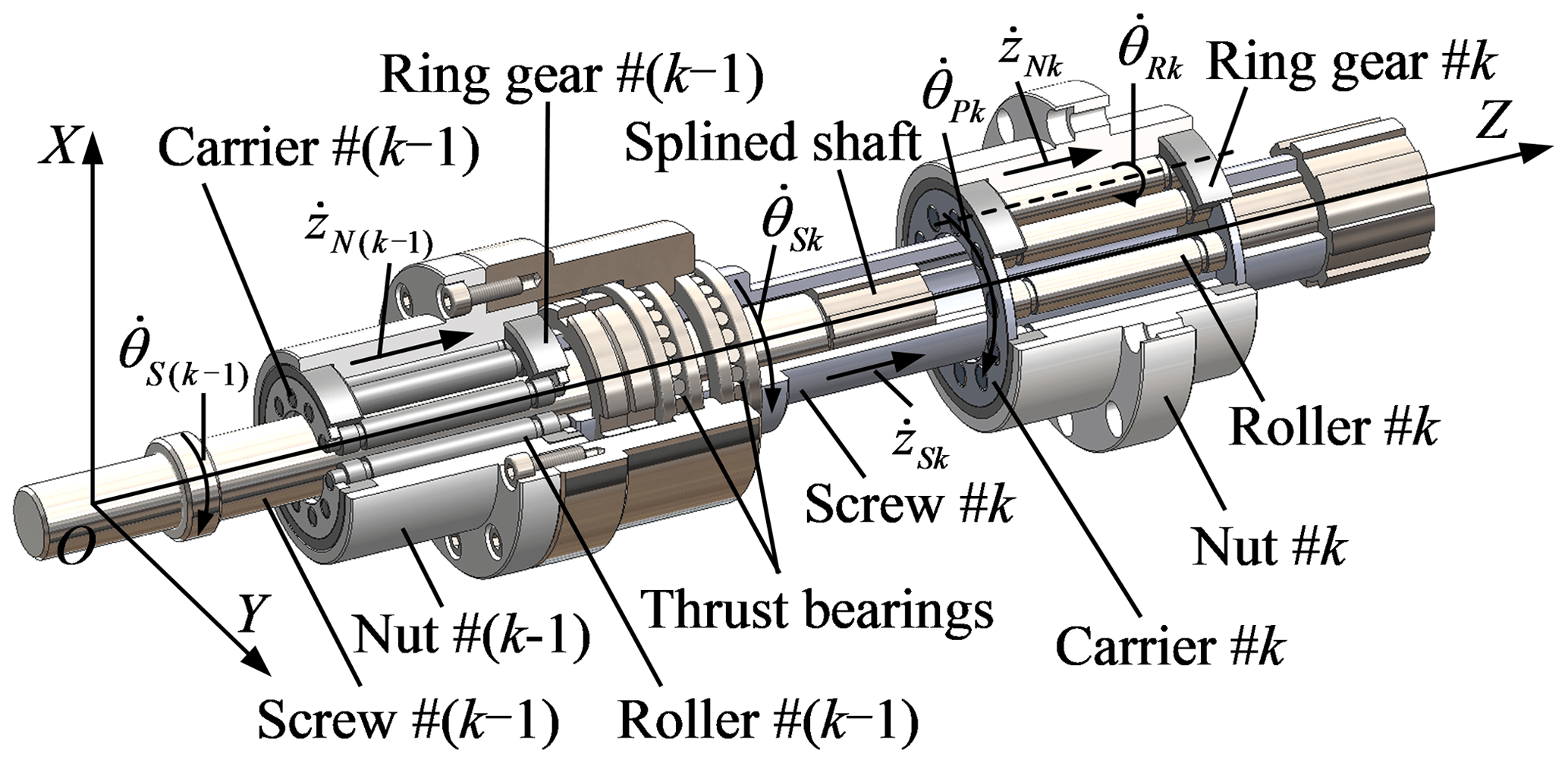
Figure 1Structure and motion analysis of the multi-stage planetary roller screw mechanism (multi-stage PRSM).
Using Eqs. (1)–(3), the kinetic energy of screws TS in the multi-stage PRSM can be derived as
where JSk and mSk are the moment of inertia and the mass of screw #k. As the rotation of all nuts shown in Fig. 1 is constrained, the kinetic energy of nuts TN is
where mNk is the mass of nut #k.
According to the motion analysis shown in Fig. 1, the kinetic energy of carriers TP is written as
where JPk and mPk are the moment of inertia and the mass of carrier #k. The kinetic energy of rollers TR is derived as
where NRk is the total number of roller #k, and JRk and mRk are the moment of inertia and the mass of roller #k. Then, the total kinetic energy of the multi-stage PRSM Ttotal is
Substituting Eqs. (6)–(9) into Eq. (10), the total kinetic energy Ttotal can be expressed as a function of the rotational velocities of the screw and carriers:
2.2 Generalized forces and motion equations
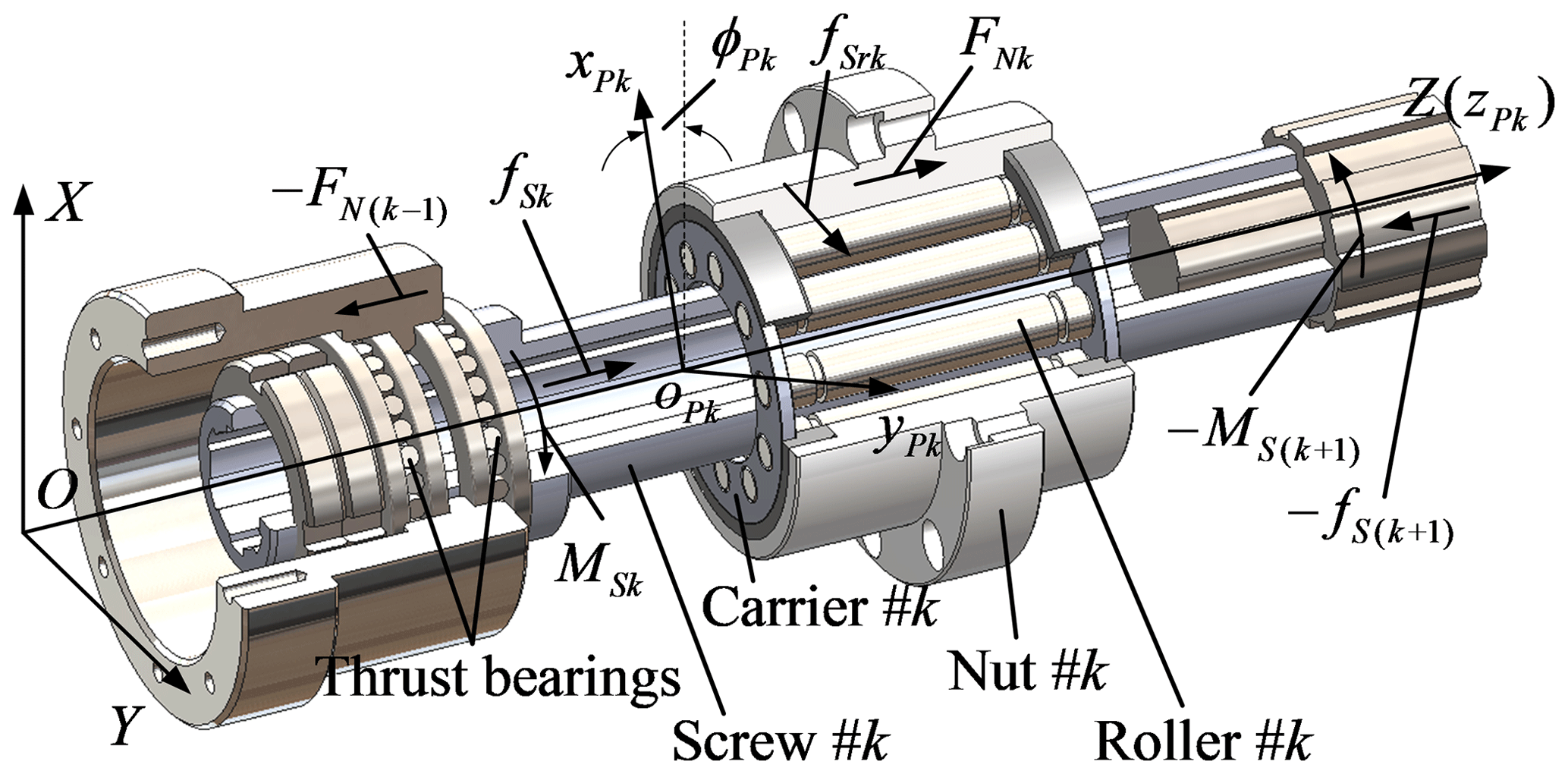
As shown in Fig. 2, MSk and fSk are the driven torque and the friction force acting on the internal spline teeth of screw #k. FNk is the external force acting on nut #k, and fSrk is the friction force between screw #k and roller #k. oPk–xPkyPkzPk is a local coordinate system fixed at the centre of carrier #k. ϕPk is the angle between the X axis and xPk axis. There is no slip at the nut–roller interface if screws, rollers and nuts are regarded as rigid bodies, and manufacturing and assembly errors are not included. Besides, the friction coefficients in thrust bearings are usually very small. Hence, the friction force at the nut–roller interface and that in thrust bearings are ignored in this paper. When the driven torque MSk is given, the friction force fSk can be expressed as
where μSS is the friction coefficient between external and internal spline teeth, and rSSk is the nominal radius of internal spline teeth on screw #k. sign() is a symbolic function, and sign is defined as
As mentioned by Fu et al. (2018), the slip velocity between screw #k and roller #k can be represented in the local coordinate system oPk–xPkyPkzPk as
where rSrk, rRsk, φSrk and φRsk are the contact radii and angles at the screw–roller interface, which can be obtained from the model developed by Fu et al. (2017). According to Coulomb's law, the friction force fSrk is
where fSrxk, fSryk and fSrzk are the X, Y and Z components of the friction force fSrk, μSR is the friction coefficient at the screw–roller interface, FSrk is the contact force between screw #k and roller #k, and HPk is the rotational matrix relating to the global coordinate system O–XYZ and local coordinate system oPk–xPkyPkzPk:
Based on the Lagrange method, the generalized force corresponding to the rotational velocity of the screw can be given as
where is the external force acting on the last nut, MS1 is the driven torque acting on screw #1 and is the velocity of the contact point on screw #k represented in the local coordinate system oPk–xPkyPkzPk as
The generalized force corresponding to the rotational velocity of carrier #k is
where is the velocity of the contact point on roller #k represented in the local coordinate system oPk–xPkyPkzPk as
where LSk is the lead of screw #k.
Using the total kinetic energy shown in Eq. (11) and the generalized forces given in Eqs. (17) and (19), the motion equation of the multi-stage PRSM is given as
and Eq. (21) can be rewritten as
The motion equation shown in Eq. (22) includes (nT+1) nonlinear equations. As the contact force, FSrk, between screw #k and roller #k and the driven torque, MSk, acting on the internal spline teeth of screw #k are not given, more equations should be added in order to solve Eq. (22).
According to the equilibrium of the torques and forces acting on screw #k, the rotational and translational motion equations of screw #k are
where FSrzk is the axial component of the contact force between screw #k and roller #k and can be given as
where βSk is the flank angle of screw #k.
Similarly, the motion equation corresponding to the axial translation of roller #k and nut #k is given as
where FNk is the external force acting on nut #k and NRk is the total number of roller #k. There are (4nT−1) unknowns in Eqs. (22)–(26) which provide (4nT−1) nonlinear equations. The motion and the forces acting on roller #k, screw #k and nut #k in the multi-stage PRSM can be obtained by solving Eqs. (22)–(26).
3.1 Transient and steady-state behaviours
A two-stage PRSM (nT=2) is used as an example in this section. The structural and mass parameters of screw #1, nut #1, roller #1 and carrier #1 are given as follows. The nominal radii of screw #1, roller #1 and nut #1 are rS1=9.75, rR1=3.25 and rN1=16.25 mm, respectively. The lead, start number and flank angle of screw #1 are LS1=10 mm, nS1=5 and βS1=45∘, respectively. The total number of roller #1 is NR1=7. The mass of roller #1 and nut #1 are mR1=0.017 and mN1=2.5 kg. The inertia moments of screw #1, roller #1 and carrier #1 are JS1=55, JR1=0.08 and JP1=3 kg mm2, respectively. The structural and mass parameters of screw #2, nut #2, roller #2 and carrier #2 are rS2=16.5, rN2=27.5, rR2=5.5, nS2=5, LS2=10, βS2=45 mm, NR2=7, mS2=0.77, mN2=18, mR2=0.04 kg, JS2=170, JR2=0.48 and JP2=12 kg mm2. The nominal radius of internal spline teeth on screw #2 is rSS2=13 mm.
When the external force acting on nut #2 is FN2=5000 N, and the rotational velocity of the screw is 100 rad s−1. The transient and steady-state behaviours of the two-stage PRSM are shown in Fig. 3a–d. In Fig. 3a,
where ζPSk is the rotational velocity ratio of carrier #k to the screw.

Figure 3Transient and steady-state behaviours of the two-stage PRSM: (a) rotational velocity ratios, (b) driven torque acting on screw #k, (c) axial component of the contact force at the screw #k–roller #k interface, (d) efficiency and friction force between screw #2 and screw #1.
Because the axial movement of screw #2 is driven by nut #1 in the two-stage PRSM, the contact fore at the screw#1–roller #1 interface is larger than at the screw #2–roller #2 interface. Thus, the slope of ζPS1 is steeper than that of ζPS2 before the steady state is reached, as shown in Fig. 3a. It takes carrier #1 about 0.14 ms to reach at the steady state. After t=0.46 ms, carrier #2 reaches at the steady state and the value of ζPS2 is larger than that of ζPS1. Because the helix angle of screw #2 is smaller than that of screw #1, the contact point at the screw #2–roller #2 interface is closer to the point of tangency between their pitch circles. This will reduce the slip between screw #2 and roller #2. When the rotational velocity of carrier #k increases, the tangential component of the slip velocity and the friction torque acting on screw #k decrease. Therefore, the values of driven torques, MS1 and MS2, at the beginning of the simulation are larger than those at the steady state, as shown in Fig. 3b. As the rotational movement of screw #2 is driven by screw #1, the value of MS1 is much larger than that of MS2 all the time. It should be noticed that the nominal radius of screw #1 is smaller than that of screw #2. After t=0.14 ms, the value of MS2 remains stable for a short time and then reduces to the steady-state value. The difference between the values of MS1 and MS2 is the largest at t=0 ms.
The axial component of the friction force between screw #k and roller #k increases when the rotational velocity of carrier #k increases. This will lead to the increase of the contact force between screw #k and roller #k, as shown in Fig. 3c. Because the value of FSrz1 is also influenced by the friction force at the screw #1–screw#2 interface, it decreases when the driven torque of screw #2 decreases. The contact force between screw #1 and roller #1 is always larger than between screw #2 and roller #2. In Fig. 3d, the efficiency η is expressed as
where FN2 is the external force of acting on nut #2 and MS1 is the driven torque acting on screw #1.
As shown in Fig. 3d, the efficiency of the two-stage PRSM is less than 0.45 at the beginning of the simulation and it increases nearly to 0.80 at the steady state. This is because that the driven torque of screw #1 decreased during the simulation. The friction force between screw #1 and screw #2 is also as shown in Fig. 3d. According to Eq. (12), the value of friction force varies with changes in the driven torque of screw #2. Thus, the change of fS2 in Fig. 3d is similar to that of MS2 in Fig. 3b.

Figure 4Influence of friction coefficients on (a) rotational velocity ratios, (b) axial component of the contact force at the screw #k–roller #k interface, (c) efficiency and (d) friction force between screw #2 and screw #1.
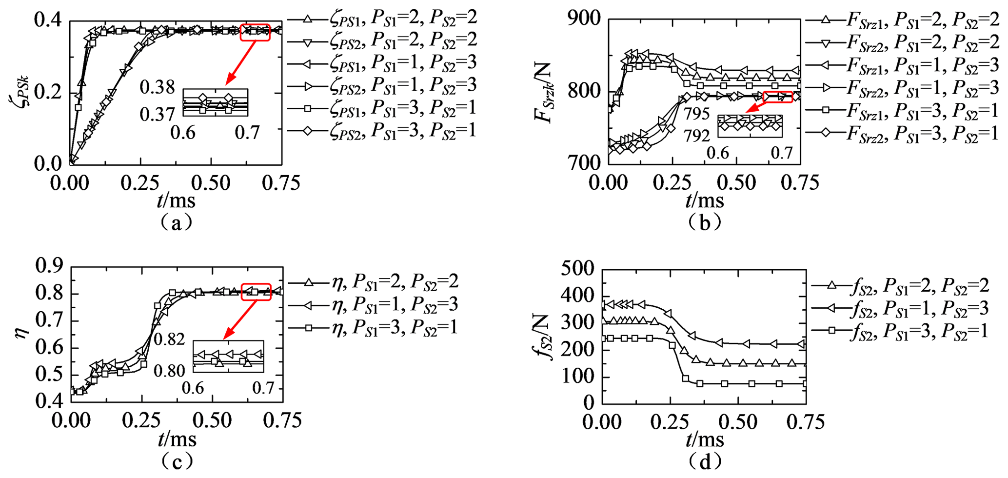
Figure 5Influence of thread pitches on (a) rotational velocity ratios, (b) axial component of the contact force at the screw #k–roller #k interface, (c) efficiency and (d) friction force between screw #2 and screw #1.
3.2 Influence of friction coefficients
When the friction coefficient between the screw and roller is 0.1 or 0.2, and that between screw #1 and screw #2 is 0.2 or 0.3, the transient and steady-state behaviours of the two-stage PRSM are as shown in Fig. 4a–d.
Because the rolling of rollers is driven by friction forces at the screw–roller interface, the slope of ζPS1 or ζPS2 increases with the increase in μSR, as shown in Fig. 4a. The friction coefficient between screw #1 and screw #2 has a slight effect on the values of ζPS1 and ζPS2. According to Eqs. (15), (19) and (22), the friction forces at the screw–roller interface and the external forces acting on nuts have no influence on the values of ζPS1 and ζPS2 when the rotational accelerations of carriers #1 and #2 are zero. As shown in Fig. 4a, the values of ζPS1 and ζPS2 remain steady at the steady state under different friction coefficients. As shown in Fig. 4b, the contact forces between the screw and rollers increase when the friction coefficient between threads is increased. The axial components of friction forces at the screw–roller interface have greater influence on the contact forces at the interface than the tangential components. The difference between the contact force at t=0 and t=0.75 ms also increases with the increase in the friction coefficient between threads, as shown in Fig. 4b. Because the forces acting on the splined shaft can not affect the forces acting on roller #2, the contact force between screw #2 and roller #2 is independent from the friction coefficient between screw #1 and screw #2.
As Fig. 4c shows, the efficiency decreases with the increase in the friction coefficient at the screw–roller interface. Meanwhile, the friction coefficient between screw #1 and screw #2 has a slight effect on the efficiency. This is because the friction force between screw #1 and screw #2, as shown in Fig. 4d, is much smaller than the external force acting on nut #2. Besides, the increase of the friction coefficient at screw #1 and screw #2 can only lead to a small increase in the contact force at the screw #1 and the roller #1 interface, as shown in Fig. 4b. As Fig. 4d shows, the friction force between screw #1 and screw #2 increases with the increase in the friction coefficients. This is because the driven torque acting on screw #2 is influenced by the friction force between screw #2 and roller #2. As Fig. 4d shows, the friction coefficient between the screw and rollers has greater influence on the value of fS2 at the beginning of simulation, and that between screws #1 and #2 has greater influence on the value of fS2 at the steady state.
3.3 Influence of thread pitches
When the sum of pitches of screw #1 and screw #2 is equal to 4 mm and those are chosen from 1 to 3 mm, the transient and steady-state behaviours of the two-stage PRSM are as shown in Fig. 5a–d.
When the thread pitches decrease, the tangential components of friction forces at the screw–roller interface increase and the contact point on the screw is close to the point of tangency between pitch circles. As shown in Fig. 5a, when the pitch of screw #1 is decreased, it takes ζPS1 less time to reach at the steady state, followed by an increase in steady-state value of ζPS1. The change of the curve of ζPS2 in Fig. 5a is similar to that of ζPS1. As shown in Fig. 5b, the contact force at the screw #2–roller #2 interface slightly increases when the pitch of screw #2 is increased. This is because the axial component of the friction force at the screw #2–roller #2 interface increases with the increase in the pitch of screw #2 and the pitch of screw #1 has no effect on the friction force. The increase of the pitch of screw #2 leads to the increase in the driven torque acting on screw #2. It enlarges the friction force between screw #1 and screw #2, as shown in Fig. 5d. By comparing Fig. 5b and d, it can be found that the influence of the pitch of screw #2 on the friction force at the screw #1 and the screw #2 interface is much greater than at the screw #2–roller #2 interface. Therefore, the value of FSrz1 decreases when the pitch of screw #1 is increased.
As shown in Fig. 5c, the pitches of screws have slight influence on the steady-state efficiency of the two-stage PRSM when the sum of pitches is a constant. It should be noticed that if the length of a roller is a constant, the number of thread teeth on the roller will increase with the decrease in the thread pitch. Therefore, the pitch of screw #1 can be smaller than that of screw #2 in order to reduce the contact forces acting on thread teeth at the screw #1–roller #1 interface. As shown in Fig. 5c, the value of fS2 increases with the increase in the pitch of screw #2.
A rigid-body dynamic model of multi-stage planetary roller screw mechanism (PRSM) has been proposed in this paper. A structure and motion analysis of multi-stage PRSM were presented, and the total kinetic energy of the mechanism was calculated. The generalized forces corresponding to the rotational movements of the screw and carriers were derived by using the Lagrange method. The motion equations of multi-stage PRSM were developed. Based on the examples provided in this paper, several conclusions are listed below.
Although the nominal radius of screw #1 is smaller than that of screw #2, the driven torque and contact force acting on screw #1 are larger than those acting on screw #2. It will take carrier #2 more time than carrier #1 to reach at the steady state. When the pitches of screw #1 and screw #2 are the same, the rotational velocity of carrier #2 is larger than that of carrier #1 at the steady state.
The efficiency of the two-stage PRSM decreases with the increase in the friction coefficient at the screw–roller interface. The friction coefficient between screw #1 and screw #2 has a slight effect on the efficiency. These friction coefficients have no effect on the rotational velocities of carriers. The friction coefficient between the screw and rollers has greater influence on the friction force between screw #1 and screw #2 at the beginning of simulation.
When the sum of the pitches of screw #1 and screw #2 is a constant, the pitches have little influence on the efficiency of the two-stage PRSM. The influence of the pitch of screw #2 on the friction force at the screw #1–screw #2 interface is much greater than at the screw #2–roller #2 interface. The axial component of contact force between screw #1 and roller #1 decreases with the increase in the pitch of screw #1.
All data, models, and codes generated or used during the study are available from the corresponding author upon request.
XL proposed the theory of the modelling method, analysed numerical results and wrote the paper; GL provided guidance on theoretical methods and edited the manuscript; XF prepared the figures; SM edited the manuscript.
The authors declare that they have no conflict of interest.
This article is part of the special issue “Robotics and advanced manufacturing”. It is not associated with a conference.
We would like to thank David Bowen for providing the language help in this paper.
This research has been supported by the National Natural Science Foundation of China (grant nos. 51905428, 51875458, 51535009), the Natural Science Basic Research Plan in Shaanxi Province of China (grant no. 2020JQ-178), and the China Scholarship Council (grant nos. 202006290149 and 201906295012).
This paper was edited by Guimin Chen and reviewed by four anonymous referees.
Abevi, F., Daidie, A., Chaussumier, M., and Sartor, M.: Static load distribution and axial stiffness in a planetary roller screw mechanism, J. Mech. Des.-T. ASME, 138, 1–11, https://doi.org/10.1115/1.4031859, 2016.
Auregan, G., Fridrici, V., Kapsa, P., and Rodrigues, F.: Experimental simulation of rolling-sliding contact for application to planetary roller screw mechanism, Wear, 332–333, 1176–1184, https://doi.org/10.1016/j.wear.2015.01.047, 2015.
Badrinarayanan, S., Kumar, V. R., and Bhinder, K. S.: Electro mechanical linear actuator using roller screws, IOP Conf. Ser.-Mat. Sci., 402, 1–10, https://doi.org/10.1088/1757-899X/402/1/012101, 2018.
Fu, X. J., Liu, G., Ma, S. J., Tong, R. T., and Lim, T. C.: A comprehensive contact analysis of planetary roller screw mechanism, J. Mech. Des.-T. ASME, 139, 1–11, https://doi.org/10.1115/1.4034580, 2017.
Fu, X. J., Liu, G., Tong, R. T., Ma, S. J., and Lim, T. C.: A nonlinear six degree of freedom dynamic model of planetary roller screw mechanism, Mech. Mach. Theory, 119, 22–36, https://doi.org/10.1016/j.mechmachtheory.2017.08.014, 2018.
Fu, X. J., Liu, G., Ma, S. J., Tong, R. T., and Li, X.: An efficient method for the dynamic analysis of planetary roller screw mechanism, Mech. Mach. Theory, 150, 1–15, https://doi.org/10.1016/j.mechmachtheory.2020.103851, 2020.
Jones, M. H. and Velinsky, S. A.: Kinematics of roller migration in the planetary roller screw mechanism, J. Mech. Des., 134, 1–6, https://doi.org/10.1115/1.4006529, 2012.
Jones, M. H. and Velinsky, S. A.: Contact kinematics in the roller screw mechanism, J. Mech. Des., 135, 1–10, https://doi.org/10.1115/1.4023964, 2013.
Jones, M. H., Velinsky, S. A., and Lasky, T. A.: Dynamics of the planetary roller screw mechanism, J. Mech. Robot., 8, 1–6, https://doi.org/10.1115/1.4030082, 2016.
Karm, W. and Mare, J. C.: Modelling and simulation of mechanical transmission in roller-screw, Aircr. Eng. Aerosp. Tec., 81, 288–298, https://doi.org/10.1108/00022660910967273, 2009.
Ma, S. J., Zhang, T., Liu, G., and He, J. P.: Bond graph-based dynamic model of planetary roller screw mechanism with consideration of axial clearance and friction, P. I. Mech. Eng. C-J. Mec., 232, 2899–2911, https://doi.org/10.1177/0954406217727631, 2017.
Morozov, V., Fadeev, P., Shtych, D., Belyaev, L., and Zhdanov, A.: Vibration decrease of electromechanical actuators based on roller screw mechanisms, Matec. Web Conf., 129, 1–5, https://doi.org/10.1051/matecconf/201712906026, 2017.
Qiao, G., Liu, G., Shi, Z. H., Wang, Y. W., Ma, S. J., and Teik, L.: Effect of friction torque on electromechanical brake system dynamics, SAE International Journal of Vehicle Dynamics, Stability, and NVH, 1, 471–479, https://doi.org/10.4271/2017-01-1902, 2017.
Qiao, G., Liu, G., Ma, S. J., Wang, W. Y., Li, P., and Lim, T. C.: Thermal characteristics analysis and experimental study of the planetary roller screw mechanism, Appl. Therm. Eng., 149, 1345–1358, https://doi.org/10.1016/j.applthermaleng.2018.12.137, 2019.
Sandu, S., Biboulet, N., Nelias, D., and Abevi, F.: An efficient method for analyzing the roller screw thread geometry, Mech. Mach. Theory, 126, 243–264, https://doi.org/10.1016/j.mechmachtheory.2018.04.004, 2018.
Wu, L. P., Ma, S. J., Wang, Q., and Liu, G.: Dynamic Model of Planetary Roller Screw Mechanism with Considering Torsional Degree of Freedom, Matec. Web Conf., 306, 1–5, https://doi.org/10.1051/matecconf/202030601003, 2020.
Xie, Z. J., Xue, Q. X., Wu, J. Q., Gu, L., Wang, Q. L., and Song, B. Y.: Mixed-lubrication analysis of planetary roller screw, Tribol. Int., 140, 1–9, https://doi.org/10.1016/j.triboint.2019.105883, 2019.
Zhang, D. W., Zhao, S. D., Wu, S. B., Zhang, Q., Fan, S. Q., and Li, J. X.: Phase characteristic between dies before rolling for thread and spline synchronous rolling process, Int. J. Adv. Manuf. Tech., 81, 513–528, https://doi.org/10.1007/s00170-015-7146-7, 2015.
Zhang, W. J., Liu, G., Tong, R. T., and Ma, S. J.: Load distribution of planetary roller screw mechanism and its improvement approach, P. I. Mech. Eng. C-J. Mec., 230, 3304–3318, https://doi.org/10.1177/0954406215610361, 2016.