the Creative Commons Attribution 4.0 License.
the Creative Commons Attribution 4.0 License.
Solution Region Synthesis Methodology of RCCC Linkages for Four Poses
Jianyou Han
Yang Cao
This paper presents a synthesis methodology of RCCC linkages based on the solution region methodology, R denoting a revolute joint and C denoting a cylindrical joint. The RCCC linkage is usually synthesized via its two defining dyads, RC and CC. For the four poses problem, there are double infinite solutions of the CC dyad, but there is no solution for the RC dyad. However, if a condition is imposed that leads to a coupling of the two dyads, a maximum of four poses can be visited with the RCCC linkage. Unfortunately, until now, there is no methodology to synthesize the RCCC linkage for four given poses besides optimization method. According to the coupling condition above, infinite exact solutions of RCCC linkages can be obtained. For displaying these RCCC linkages, we first build a spherical 4R linkage solution region. Then solutions with circuit and branch defects can be eliminated on this solution region, so that the feasible solution region is obtained. An RCCC linkage can be obtained by using the prescribed spatial positions and selected a value on the feasible solution region. We take values on the feasible solution region by a certain step length and many exact solutions for RCCC linkages can be obtained. Finally we display these solutions on a map, this map is the solution region for RCCC linkages.
- Article
(4300 KB) - Full-text XML
- BibTeX
- EndNote
The synthesis of spatial RCCC linkages has been received much more attentions recently. A formulation based on dual algebra is proposed for the approximate synthesis of RCCC linkage motion generation (Angeles, 2014). An approach is introduced for the synthesis of the axode of an RCCC linkage (Figliolini et al., 2016). An RCCC linkage is synthesized by a robust optimization method (Al-Widyan and Angeles, 2012). Fourier series theory is used for path generation of RCCC linkage (Sun et al., 2012, 2017). A semi-graphical approach is proposed for the synthesis of 4C linkage for five given poses to obtain a robust solution (Bai and Angeles, 2012). A complete classification scheme is developed for planar, spherical 4R and spatial RCCC mechanisms (Murray and Larochelle, 1998). Larochelle addressed the issue of branch and circuit analysis of spatial 4C mechanisms for rigid body guidance (Larochelle, 2000).
There are no exact solutions for the synthesis of RCCC linkage for four prescribed coupler poses (Bai and Angeles, 2012). In some literatures (Bai and Angeles, 2015), RC dyad is synthesized by optimization method and CC dyad is synthesized by line congruence, only one approximate solution for RCCC linkage can be obtained for four poses. In this paper, we add constraints between RC dyad and CC dyad, thus the number of unknowns more than the number of equations and infinite exact solutions for RCCC linkage are obtained. For synthesizing more RCCC linkages, we propose a solution region methodology by which infinite exact solutions can be obtained. The synthesis process of this methodology is separated into two parts. The first part is to build a spherical 4R linkage solution region based on Burmester curves. The Burmester curves are determined by four orientations from the four poses. Then we eliminate those solutions having circuit and branch defects and obtain the feasible solution region. In second part, we couple the constraint conditions for an RC dyad and a CC dyad, and obtain 23 equations with 24 unknowns. Therefore, there is one parameter to be chosen freely. Finally we select different values on the feasible solution region, and solve these equations using Bertini software, and build an RCCC linkage solution region for displaying these solutions. The solution region methodology introduced in this paper has been applied in the synthesis of planar and spherical linkages (Han and Qian, 2009; Yang et al., 2011, 2012; Yin et al., 2012; Cui and Han, 2016). We also synthesized the 5-SS platform linkage by solution region methodology (Han and Cui, 2017). We proposed the primary idea of the synthesis of RCCC linkages for four poses by solution region map (Cao and Han, 2016; Han and Cao, 2017), but the method of building solution region isn't given.
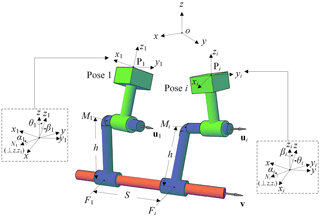
A spatial CC dyad is shown in Fig. 1. The CC dyad is meant to carry the rigid body through a set of given poses, specified by coordinates pi (pix, piy, piz) and orientations (θi, αi, βi) respect to a reference coordinate frame (xyz) as shown in Fig. 1, where orientation angles θi, αi, βi are three Euler angles. The unit vectors u1 and v are along the CC dyad cylindrical pairs moving and fixed axes, respectively. Vector ui denotes the unit vector of u1 at the ith pose. The CC dyad can be geometrically regarded as a link composed of two skew lines, jointed each other by means of a third line, their common perpendicular (Fig. 1). M1 is the intersection point of the common perpendicular and moving axis. F1 is the intersection point of the common perpendicular and fixed axis. h donates the distance between the moving and the fixed axes of the CC dyad. S denotes the sliding displacement of the cylindrical pair from the first to the ith pose, S is defined as
where Si denotes the sliding displacement of the cylindrical pair from the pose i-1 to the pose i. When the sliding direction of the cylindrical pair (while the coupler moves from one pose to the next) is in the same direction with vector v, Si is positive, whereas negative. Note that the CC dyad must satisfy two constraints. The angle of twist between the fixed axis and the moving axis must remain constant from 1st pose to ith pose. The moment of vector ui about axis v must remain constant from 1st pose to ith pose. Hence, the CC dyad constraint equations can be written as follows.
In Eq. (2), m1, mi, f1 and fi are the position vectors of M1, Mi, F1 and Fi respectively. Vectors u1, ui and v are unit vectors, Therefore
For ensuring the vector m1−f1 is orthogonal to their unit vectors, we have
In Eq. (1), ui can be expressed as
In Eq. (5), Ri is a rotation matrix which rotates rigid body from 1st to ith orientation. For rotating rigid body from 1st to ith orientation, first, we rotate the rigid body to make its orientation coincide with the reference coordinate by three Euler angles (-β1, -α1 and -θ1 around the z-, x- and z-axes, respectively), then rotate it to the ith by three Euler angles (θi, αi and βi around the z-, x- and z-axes, respectively). Therefore Ri can be expressed as
where X, Z are pure rotation matrixes around x-, z-axes, respectively. All rotation matrixes follow the right-hand rule.
mi and fi can be expressed as matrix forms
where U1x, Uix, Vx and Pix are cross-product matrixes of vectors u1, ui, v, and pi.
Equations (1) to (4) constitute a set of 2n+2 () constraint equations with twelve unknowns, which are scalar components of u1, v, m1 and f1. Therefore, the maximum number of poses, which can be specified for a CC dyad to be used for rigid body guidance, is five.
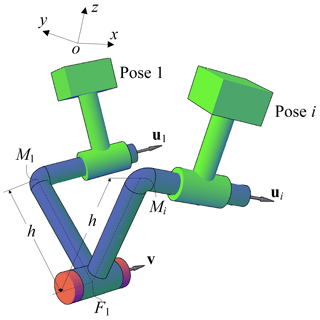
The RC dyad shown in Fig. 2 must satisfy all of the constraints imposed by a CC dyad plus an additional displacement constraint, the sliding Si along the fixed axis is zero
Equations (1), (2), (3), (4) and (9) constitute a set of 3n+1 () constraint equations with twelve unknowns, which are scalar components of u1, v, m1 and f1. Therefore, the maximum number of poses, which can be specified for a CC dyad to be used for rigid body guidance, is three with arbitrary choice of any two scalars.
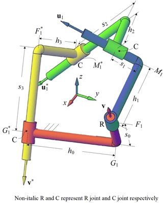
An RCCC linkage is shown in Fig.3. We use u1, v, m1 and f1 to represent the RC dyad and use , v∗, and to represent the CC dyad. If we synthesize RC dyad and CC dyad separately, then simply couple the RC dyad and CC dyad with a coupler link for a RCCC linkage to be used for rigid body guidance, the maximum number of specified poses is three. When we add a constraint between two dyads instead of Eq. (9), we have
where g1 is the position vector of G1 as shown in Fig. 3. g1 can be expressed by vectors v, f1, v∗ and . Then the RCCC linkage synthesis problem involves 5n+3 () equations, Eqs. (1), (2), (3), (4) and (10). These equations are to be solved for 24 unknowns, which are components of the eight vectors u1, v, m1, f1, , v∗, and . The maximum number of poses, which can be specified for an RCCC linkage to be used for rigid body guidance, is four with arbitrary choice of one scalar.
We separate the synthesis process into two parts. For determining the range of αc (αc is arbitrary choice from 24 unknowns, here αc is defined as the latitude of a point on spherical circle curve which will be mentioned below), we build a spherical 4R linkage feasible solution region. Then we set up the synthesis formulation for synthesizing RCCC linkages.
3.1 Determination of spherical Burmester curves and Building of the spherical 4R linkage solution regions
In this section, we determine the Burmester curves and build spherical 4R linkage solution region by these curves. On this solution region, we can classify the mechanism types and eliminate circuit and branch defects.
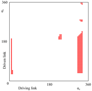
Figure 7RCCC solutions corresponding the parts on the feasible spherical 4R linkage solution region.
3.1.1 Spherical Burmester curves
Unit vector v is along the fixed axis, whereas unit vector u1 is along the moving axis. For the four given poses problem, n=4.
Let
then Eq. (1) can be rewritten as
Since unit vector v cannot be zero, B must be non-full rank. Therefore, its determinant is zero, i.e., |B|=0. The spherical Burmester circle point curve can be expressed as
Likewise, the spherical Burmester center point curve can be expressed as
where (Bai and Angeles, 2012).
We use spherical coordinates on the unit sphere, i.e., latitude and longitude, to describe the unit vectors of all four cylindrical directions. Let αc and βc be the longitude and latitude of a point on spherical circle curve, and αo and βo be the latitude and longitude of a point on spherical center curve.
Therefore
Each point on the Burmester circle curve corresponds to the point on the Burmester center curve. Connecting the corresponding points, we obtain an RR dyad. A spherical 4R linkage can be synthesized by selecting two different points on the Burmester circle (or center curve).
3.1.2 Building of the spherical solution regions
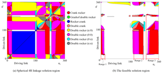
Let αc (the latitude of Burmester circle point curve) as the x- and y-axes, we build a solution region for displaying infinite spherical 4R linkage solutions, as shown in Fig. 6a. Building process in detail is shown in Sect. 4. The circuit and branch defects can be eliminated on this solution region. The feasible solution region is built after eliminating the defects (Larochelle, 2000) from spherical 4R solution region, as shown in Fig. 6b.
3.2 The synthesis formulation of RCCC linkages
We have discussed the number of the unknowns and the equations for synthesizing RCCC linkages for four poses above. For synthesizing driving link, substituting Eq. (5) into Eq. (1), we have
Substituting Eqs. (7) and (8) into Eq. (2), we have
Because the Eqs. (16) and (17) can apply for both CC and RC dyad, we use u1, v, m1, f1 to represent the direction and position vectors for RC dyad (driving link); we use , v∗, , to represent the direction and position vectors for CC dyad (driven link). The two sets of vectors can be applied for Eqs. (16) and (17). Therefore, substituting the unit vectors and position vectors of driven link into the Eqs. (16) and (17), we have
The twelve equations are list below
Equations (3) and (4) are unit vectors equations and orthogonality equations (Suh and Radcliffe, 1978) for driving link. We rewrite the Eqs. (3) and (4) with unknowns , v∗, and to represent the unit vectors equations and orthogonality equations for driven link
Equation (10) constrains the sliding displacement between the driving link and the fixed link. So, there are 23 equations (Eqs. 3, 4, 10, 20 and 21) to solve 24 unknowns, i.e., u1, v, m1, f1, , v∗, and . We have free choice of one from 24 unknowns.
In this paper, we select αc on x-axis of spherical 4R linkage feasible solution region as the arbitrary choice scalar. Then 23 equations can be solved for other 23 unknowns using the Bertini software (Bates et al., 2006).
In Table 1, αi, βi, θi are the Euler angles and pi (pix, piy, piz) are the spatial coordinates. The design demands are:
-
Linkage type: crank rocker;
-
The ranges of x-axis of points M1 and are restricted in (−100, 100);
-
No circuit and branch defects.
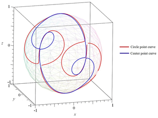
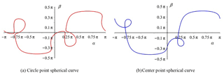
Substituting four orientations (Table 1) into Eqs. (13) and (14), the spherical Burmester circle and center point curves are obtained, as shown in Fig. 4. Substituting u1 in Eq. (15) into Eq. (13), and substituting v in Eq. (15) into (14), then Eq. (13) has only two variables αc and βc; Then Eq. (14) has only two variables αo and βo; Therefore, we convert the spatial Burmester curves into the α−β plane, as shown in Fig. 5.
Let αc (the latitude of Burmester circle point curve) as the x- and y-axes, we build a solution region for displaying infinite spherical 4R linkage solutions, as shown in Fig. 6. We classified the solution region with nine parts with different colors. In the white region, there is no linkage. The rest eight parts are classified by eight types of mechanisms as listed in Fig. 6. Circuit and branch defects can also be eliminated in this solution region. After eliminating the defects, we obtained the feasible solution region as shown in Fig. 6b. In the feasible solution region, if we want crank-rocker mechanisms, αc of x-axis must be taken values in range 1 (0∘, 19∘), range 2 (185∘, 228∘) and range 3 (262∘, 360∘), as shown in Fig. 7.
We select αc values from range 1, range 2 and range 3 (see Fig. 6b) by 5∘ of the step size. Then 247 real exact solutions for RCCC linkages are obtained by Bertini software which meet the design demands. Displaying these solutions on the feasible solution region, as shown in Fig. 7. If we take a smaller step size , the more RCCC linkage solutions can be obtained. So infinite RCCC linkages can be obtained if we take infinitesimal step size.
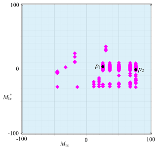
An RCCC linkage can be synthesized by taking a point on the solution region as shown in Fig. 7. For showing the specific location of RCCC linkage solutions, let x-component of m1 as x-axis; Let x-component of as y-axis, the solution region shown in Fig. 7 can be expressed as in Fig. 8. Because the ranges of them are constrained in , so that we have only 246 solutions.
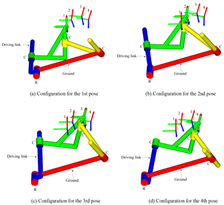
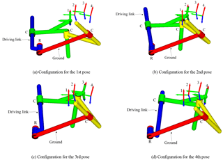
Selecting point p1 as a solution of the RCCC linkage, the results of solutions are listed in Table 2, the four configurations of the linkage are shown in Fig. 9. Linkages in Figs. 9 and 10 are automatically generated by our programmed software using visual language VC 6.0 and drawn by OpenGL software.
Selecting another point p2 as a solution of the RCCC linkage, the results of solutions are listed in Table 3, the four configurations of the linkage are shown in Fig. 10.
The methodology proposed in this paper synthesizes RCCC linkages by the solution region theory and Bertini software based on the homotopy method. Compared with optimization method and iterative method proposed in other papers, the advantage of the methodology is that more solutions can be obtained. The optimization method and iterative method usually obtain approximate solution, while this method can obtain the exact solutions.
We synthesize RCCC linkages based on the solution region methodology for four specified poses. Before the synthesis of RCCC linkage, we build the spherical 4R linkage solution region to classify the mechanism types and eliminate the solutions with defects to reduce the calculations.
The key contributions of this paper are:
-
All solutions of RCCC linkages for four specific poses are obtained. For four poses problem, only one RCCC linkage can be synthesized by the methods published before.
-
Systematic methodology is proposed in this paper, that is solution region methodology. Two illustrative examples prove that the method is effective.
The two synthesized RCCC linkages from the example section have reasonable size and are crank rocker mechanism which would simplify the control of drive system. The method not only synthesize more accurate solutions for RCCC linkage, but also provide more choices for designers. Using solution region map, the designer can filter the solutions by adding different design conditions besides the four specified poses. The solution region also can display some kinematic properties and geometric dimensions of linkages. These functions are useful for the practical application.
All the data used in this manuscript can be obtained on request from the corresponding author.
JYH proposed the idea and methodology; YC derived the equations and developed the software.
The authors declare that they have no conflict of interest.
This study is supported by the National Natural Science Foundation of China
under grant no. 51775035 and no. 51275034. Thanks to Supercomputing Center of
Chinese Academy of Sciences for its computing service.
Edited by: Doina Pisla
Reviewed by: two
anonymous referees
Al-Widyan, K. M. and Angeles, J.: The kinematic synthesis of a robust rccc mechanism for pick-and-place operations, ASME 2012 International Design Engineering Technical Conferences and Computers and Information in Engineering Conference, 579–588, 2012
Angeles, J.: Foundations for the Approximate Synthesis of RCCC Motion Generators, in: Computational Kinematics, Springer, 331–338, 2014.
Bai, S. and Angeles, J.: A Robust Solution of the Spatial Burmester Problem, J. Mech. Robot., 4, 031003, https://doi.org/10.1115/1.4006658, 2012.
Bai, S. and Angeles, J.: Synthesis of RCCC Linkages to Visit Four Given Poses, J. Mech. Robotics, 7, 031004, https://doi.org/10.1115/1.4028637, 2015.
Bates, D. J., Hauenstein, J. D., Sommese, A. J., and Wampler, C. W.: Bertini: Software for numerical algebraic geometry, http://bertini.nd.edu, 2006
Cao, Y. and Han, J.: Synthesis of RCCC Linkage to Visit Four Given Positions Based on Solution Region, Transactions of the Chinese Society for Agricultural Machinery, 8, 399–405, https://doi.org/10.6041/j.issn.1000-1298.2016.08.052, 2016.
Cui, G. and Han, J.: The solution region-based synthesis methodology for a 1-DOF eight-bar linkage, Mech. Mach. Theory, 98, 231–241, 2016.
Figliolini, G., Rea, P., and Angeles, J.: The synthesis of the axodes of RCCC linkages, J. Mech. Robot., 8, 021011, https://doi.org/10.1115/1.4031950, 2016.
Han, J. and Cao, Y.: Synthesis of 4C and RCCC Linkages to Visit Four Positions Based on Solution Region Methodology, ASME 2017 International Design Engineering Technical Conferences and Computers and Information in Engineering Conference, V05AT08A052-V005AT008A052, 2017.
Han, J. and Cui, G.: Solution Region Synthesis Methodology of Spatial 5-SS Linkages for Six Given Positions, J. Mech. Robot., 9, 044501, https://doi.org/10.1115/1.4036219, 2017.
Han, J. and Qian, W.: On the solution of region-based planar four-bar motion generation, Mech. Mach. Theory, 44, 457–465, 2009.
Larochelle, P.: Circuit and branch rectification of the spatial 4c mechanism, ASME Design Engineering Technical Conferences, Baltimore, MD, September, 10–13, 2000.
Murray, A. P. and Larochelle, P.: A classification scheme for planar 4r, spherical 4r, and spatial rccc linkages to facilitate computer animation, ASME Paper No. DETC98/MECH-5887, 1998.
Suh, C. H. and Radcliffe, C. W.: Kinematics and mechanisms design, Wiley, 1978.
Sun, J., Mu, D., and Chu, J.: Fourier series method for path generation of RCCC mechanism, P. I. Mech. Eng. C-J. Mec., 226, 816–827, 2012.
Sun, J., Liu, Q., and Chu, J.: Motion generation of RCCC mechanism using numerical atlas, Mech. Based Des. Struc., 45, 62–75, 2017.
Yang, T., Han, J., and Yin, L.: A unified synthesis method based on solution regions for four finitely separated and mixed “point-order” positions, Mech. Mach. Theory, 46, 1719–1731, 2011.
Yang, T., Han, J., and Yin, L.: Spherical 4R function synthesis based on solution regions for four precision points, Transactions of the Chinese Society for Agricultural Machinery, 10, 200–206, 2012.
Yin, L., Han, J., Mao, C., Huang, J., and Yang, T.: Synthesis method based on solution regions for planar four-bar straight-line linkages, J. Mech. Sci. Technol., 26, 3159–3167, 2012.


