the Creative Commons Attribution 4.0 License.
the Creative Commons Attribution 4.0 License.
 | 26 May 2026
Comparison of error modeling between inverse kinematics and product of exponentials methods for a 5-DOF hybrid perfusion manipulator
Hui Yang
Long Bai
Zhouxiang Jiang
Xiangyun Li
Zhongjie Long
Establishing a comprehensive error model that encapsulates all kinematic error parameters constitutes a critical foundation for achieving satisfactory kinematic calibration performance. In this study, a 5-DOF 5PRR+5PUS-PRPU hybrid perfusion mechanism with a variable structure is selected as the research object, and error modeling is conducted using inverse kinematics and the product of exponentials (POE) method, respectively. Comparative analysis of these two error modeling approaches is performed through kinematic calibration simulations of the hybrid mechanism. Firstly, error models of the 5-DOF hybrid perfusion mechanism are established via inverse kinematics and the POE formula method. To replicate real-world kinematic calibration scenarios, the actual kinematic parameters of the mechanism and the actual pose of the moving platform are defined. Owing to the presence of the 5PRR variable base, kinematic calibration simulations of the hybrid perfusion mechanism are executed separately when the base is positioned at different locations. The results demonstrate that, in comparison to the calibration results obtained via the traditional inverse kinematics modeling method, the mean position and orientation errors of the moving platform after kinematic calibration based on the POE error model are reduced by 89.04 % and 63.79 %, respectively. This verifies the correctness and effectiveness of the proposed POE-based error modeling method and kinematic calibration simulation approach, which can be extended to the error analysis of most parallel mechanisms.
- Article
(5331 KB) - Full-text XML
- BibTeX
- EndNote


Hybrid manipulators, integrating the advantages of high structural stiffness and high load capacity of parallel manipulators and the large workspace of serial manipulators, have been extensively applied in fields such as large-load forming, high-precision positioning machining, and aerospace applications (Huang et al., 2019; Zhao et al., 2024; Zhang et al., 2025, 2023; Xu et al., 2025). Ensuring the precise absolute positioning accuracy of the end effector is a crucial condition for the hybrid manipulators involved in high-precision machining. However, due to the various errors generated in the process of manufacturing and assembly, the actual kinematic parameters of the hybrid manipulator cannot be consistent with the theoretical values, which influences the positioning accuracy of the moving platform. Kinematic calibration, a relatively economical method that can effectively solve this problem, has attracted extensive attention from researchers over the years (Liang et al., 2026; Jiang et al., 2021; Li et al., 2025).
In general, the kinematic calibration process for parallel manipulators consists of four stages: error modeling, configuration measurement, parameter identification, and error compensation (Majarena et al., 2010). Among these, error modeling serves as the theoretical basis of kinematic calibration, which can reveal the mapping relationship between geometric error sources and the end-effector errors (Ni et al., 2016). For traditional serial manipulators, scholars have conducted in-depth research on their kinematic calibration over the past few decades using methods such as homogeneous transformation matrices (Daney, 2003; Maurine and Dombre, 1996), Denavit–Hartenberg (D-H) parameters (Feng et al., 2012), screw theory (Liu et al., 2011), and the product of exponentials (POE) formula (Chen et al., 2018; Yuan et al., 2024). Due to the existence of passive joints in limbs, it is difficult for a parallel manipulator with complex topological structures to derive the error model through the forward kinematics.
Currently, two common approaches are employed for error modeling of parallel manipulators. The first method is based on the closed-loop vector of the mechanism, which mainly obtains the mapping relationship between each kinematic parameter in the vector equation and the position of the end effector through the inverse kinematics. Then, the error model can be derived by performing full differentiation on the kinematic parameters in the equation, and this modeling approach has been widely applied in kinematic calibration of some parallel manipulators (Zhou et al., 2025; Zhang et al., 2014; Verner et al., 2005). The error models established by the second method are based on the limbs of a parallel mechanism, which regards each limb as a serial branch chain and formulates the error model of each limb. Then, the overall error model can be derived by synthesizing the error models of all limbs according to the closed-loop characteristics of the parallel mechanism (Maurine and Dombre, 1996; Liu et al., 2011; Wang et al., 2024). For example, considering the error of the universal joint in the limb, Kong et al. (2018) established the error model of the 3-PRRU parallel mechanism based on a modified D–H method, which includes all the identification error parameters. Frisoli et al. (2011) utilized the screw theory method to construct the error model of the 3-URU spatial parallel robot. According to the Lie group and Lie algebra methods of rigid-body spatial motion, Okamura and Park (1996) developed the error model for spatial serial mechanisms by means of the POE formula. To obtain the error model that satisfies completeness, continuity, and minimality, Chen et al. (2018) proposed an error modeling method of parallel mechanisms based on the POE formula, and Kong et al. (2021) applied this method to conduct kinematic calibration on the 3-PRRU parallel mechanism, which verified the correctness and effectiveness of the error model through numerical simulations and experiments. In addition, scholars have also investigated the issue of error modeling of over-constrained parallel mechanisms. Considering the deformations of components, Jiang et al. (2018) proposed a kinematic error modeling and parameter identification method for over-constrained parallel mechanisms based on inverse kinematics. Yu et al. (2021) performed error modeling, analysis, and prediction for an over-constrained extendable support mechanism by considering geometric errors, joint clearances, and link deformations. Wu et al. (2023, 2024) proposed a novel calibration method that can simultaneously identify kinematic parameters and compliance parameters of over-constrained parallel mechanisms based on the established kinetostatic model. All the above research methods can effectively improve the absolute positioning accuracy of the moving platform of the corresponding parallel mechanism.
In our previous work (Yang et al., 2021), a 5-DOF reconfigurable hybrid perfusion manipulator was proposed, which is composed of an over-constrained 5PRR parallel mechanism and a 5PUS-PRPU parallel mechanism in series, and the dimensional synthesis of the hybrid manipulator was conducted. According to the design concept of the over-constrained variable-structure parallel base in the 5-DOF hybrid perfusion manipulator, when perfusing the honeycombs of the top and edge of the spherical crown surface, the 5PRR parallel mechanism is located at the minimum and maximum limit positions, respectively. During the perfusion process, when the 5PRR parallel mechanism moves to a specific position as the first-stage mechanism, it will be fixed as the base platform of the second-stage 5-DOF 5PUS-PRPU parallel mechanism. Since the moving platform needs to carry heavy perfusion equipment and materials, the degree to which the kinematic parameters affect the motion error of the moving platform also varies when the first-stage mechanism is at different positions. Therefore, establishing an effective error model for the hybrid perfusion mechanism is a crucial foundation for improving the end perfusion precision. In this paper, the 5-DOF hybrid perfusion mechanism is taken as the research object. Error modeling of the hybrid mechanism is carried out using the traditional inverse kinematics method and the POE method. Under the same conditions, kinematic calibration simulations are conducted based on the error models established by these two methods. Finally, the correctness and effectiveness of the POE-based error modeling method proposed in this paper are verified through comparative analysis of calibration results.
The structure of this paper is arranged as follows. Section 2 briefly introduces the 5-DOF hybrid perfusion manipulator. Section 3 establishes error models for the hybrid perfusion mechanism using the traditional inverse kinematics method and the POE method. To verify the effectiveness and correctness of the POE error model, kinematic calibration simulations are conducted in Sect. 4, and comparative analysis is performed based on the calibration results. Finally, the conclusions are drawn in Sect. 5.
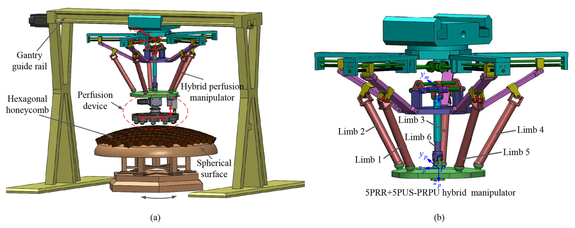
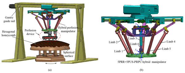
As illustrated in Fig. 1, the 5-DOF 5PRR+5PUS-PRPU hybrid manipulator is essentially composed of a 1-DOF 5PRR parallel manipulator connected with a 5-DOF 5PUS-PRPU parallel manipulator in series. Herein, the underlined P represents the actuated prismatic joint. The 5PRR parallel manipulator includes a fixed platform, five PRR limbs, and a middle platform, and the 5PUS-PRPU parallel manipulator includes five PUS limbs, one non-actuated middle passive PRPU limb, and a moving platform. Here, P, R, U, and S denote prismatic, revolute, universal, and spherical joints, respectively. During the movement process of the 5-DOF hybrid manipulator, the 5PRR parallel manipulator will be fixed when it reaches the proper position, which can be regarded as the base platform of the 5PUS-PRPU parallel manipulator in the subsequent movement. Since the PRR and PUS limbs are placed symmetrically, the angle between the adjacent limb can be represented as (i=1–5). For the ith PRR limb, the center of the actuated P joint and the first R joint is denoted by point Ai, and point Bi represents the second R joint. Similarly, the centers of P, the U joint, and the S joint in the ith PUS limb are denoted by points Ci and Di. The circumradius of the middle and moving platform is represented by rm and rp. For the convenience of describing the pose of the end effector, the coordinate systems named {B−xbybzb}, {M−xmymzm}, and {P−xpypzp} are respectively attached to the center of the fixed base, the middle platform, and the moving platform in Fig. 1. The frame {M−xmymzm} is parallel to the frame {B−xbybzb}, the xb axis is along the direction of the straight line BA1, and the zb axis is perpendicular to the fixed plane. The xp axis points to D1, and the zp axis is perpendicular to the moving platform's plane. The middle platform of the 5PRR parallel mechanism can only translate along the zb axis, and the moving platform of the 5PUS-PRPU parallel mechanism has three translational DOFs along the xp, yp, and zp axes and two rotational DOFs along the xp and yp axes, which enables the hybrid manipulator to have 5 DOFs while possessing a large workspace.
In this section, error models of the 5-DOF hybrid manipulator are established using the traditional inverse kinematics method and the POE method. For the traditional method, the closed-loop vector equation of each limb is first established, and the error model of the mechanism is derived by differentiating these equations. For the POE formula method, the error model of the entire hybrid mechanism is mainly obtained from the error models of the limbs according to the closed-loop characteristics of the hybrid mechanism. The error model established via this method can incorporate all geometric and kinematic error parameters in the limbs. Subsequently, these two error models are utilized for kinematic calibration simulations in Sect. 4.
3.1 Error modeling based on the inverse kinematics method
Prior to establishing the error model of the hybrid manipulator using the inverse kinematics method, the following assumptions are made:
-
The P and R joints in the PRR limb are accurate without errors, which causes the limbs to be restricted to the corresponding vertical planes.
-
The P, U, and S joints in the PUS limb do not contain manufacturing errors, which means that the direction of the P joint of the slider is perpendicular to the shaft of the R joint of that limb, and the two shafts of the U joint intersect perpendicularly.
-
The P, R, and U joints in the PRPU limb are ideal, which implies that the direction of the first P joint of the slider is parallel to the shaft of the R joint of that limb. Moreover, the direction of the second P joint is always the same as the direction from the center of the R joint to the center of the U joint.
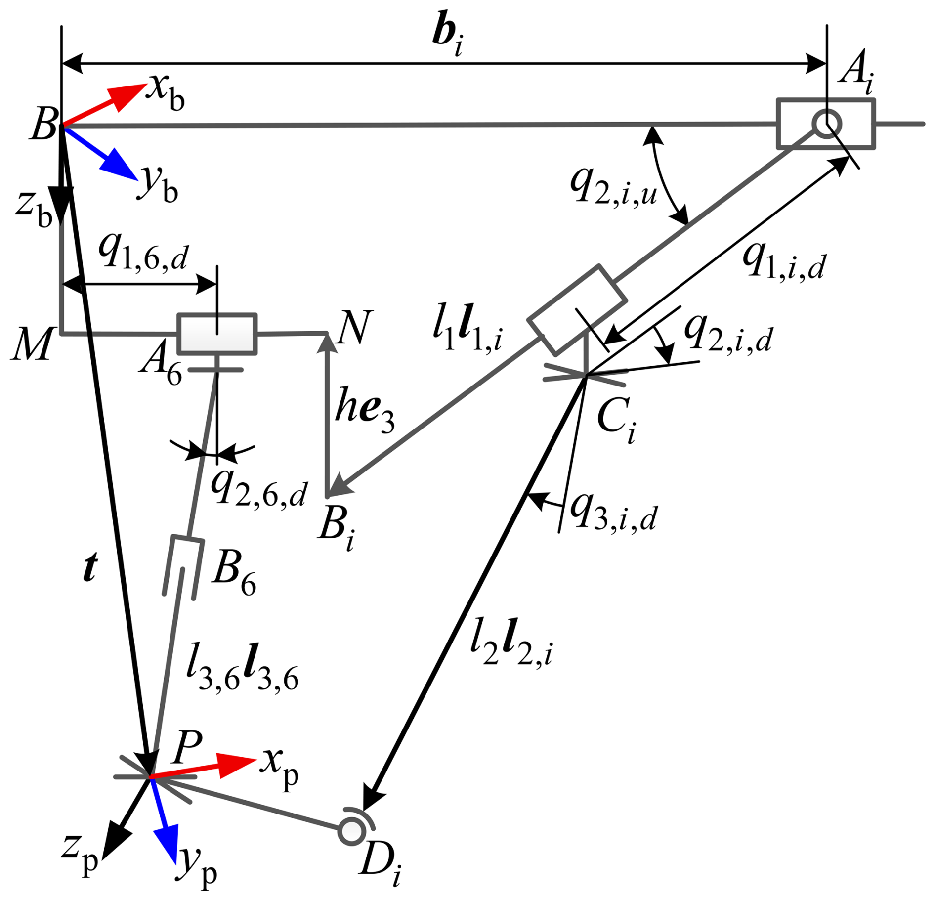
Under the above assumptions, Fig. 2 gives the kinematic diagram of the 5-DOF hybrid mechanism. Then, the closed-loop vector equation for the ith PUS limb of the hybrid manipulator can be constructed as
where l2 is the length of link CiDi, is the position vector of the moving platform in the fixed coordinate system {B−xbybzb}, l1,i and l2,i are the unit vectors along and , and bi represents the vector .
Taking the total differential of Eq. (1), we can obtain
where is the motion of the driving P joint of the PUS limb, which means is zero. l1,i and l2,i can be represented by the motions of the passive R joints , , and , and the motion errors , , and can be eliminated in the error model.
Projecting Eq. (2) onto the direction of vector l2,i and simplifying it yields
The above equation can be further simplified to the form expressed by the generalized coordinate errors and kinematic error parameters, which yields
where represents the moving platform's pose errors. is the vector of the ith limb's kinematic error parameters, and .
The coefficient matrices in Eq. (4) are given by
where
Similarly, the closed-loop vector equation for the PRPU limb can be obtained as
where b1 represents the vector ; u1,i is the unit vector along ; denotes the motion of the first P joint of the PRPU limb; rm is the radius of the circumscribed circle of the middle platform; and l1 and h denote the lengths of link AiBi and link NBi, respectively.
Taking the total differential of the above equation, we get
where l3,6 is the unit vector along and can be represented by the motion of the passive R joint , which means δl3,6 can be eliminated.
Projecting Eq. (7) onto the direction of vector l3,6 and simplifying it into the form of Eq. (4), we can get
where and are coefficient matrices, and is the vector of the kinematic error parameters of the PRPU limb.
By combining the error models of the PRR, PUS, and PRPU limbs, the kinematic error mapping model of the 5-DOF hybrid manipulator based on the inverse kinematics method can be obtained as
where
In the error model based on the inverse kinematics method, the pose error of the moving platform is represented in the form of generalized coordinate errors. However, in the process of kinematic calibration, it can be expressed by the difference between the theoretical error and the actual measured error of the end effector, which is shown as
where qa denotes the generalized coordinates of the actual measured pose of the end effector, and qn represents the generalized coordinates of the end effector calculated by the forward kinematics under the current kinematic parameters. δq, obtained from Eq. (10), can be used to iterate and update the kinematic parameters through Eq. (9).
3.2 Error modeling based on the POE formula method
3.2.1 Error modeling of the 5PRR parallel mechanism
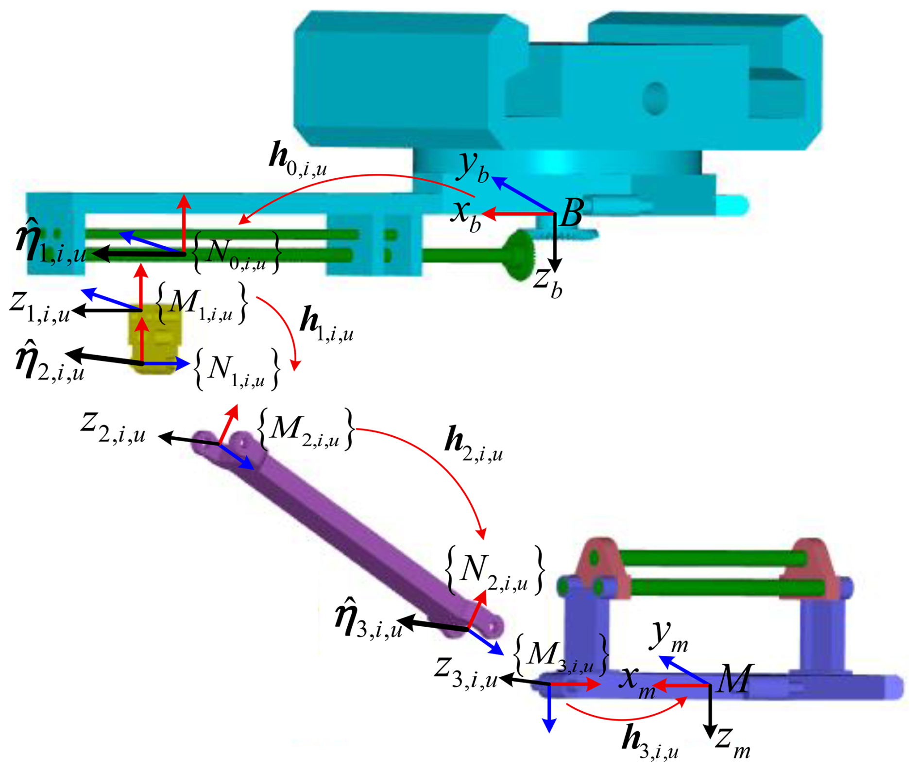
According to the error modeling principle based on the local POE formula, forward and rear local coordinate systems are attached to the joints of the limbs. The local joint coordinate frames for the ith PRR limb of the 5PRR parallel mechanism are given successively in Fig. 3. Then, the forward kinematics of the parallel mechanism, expressed by the local POE formula of the ith limb, can be obtained as
where and are the transformation matrix from to and kinematic parameters of the jth link at the original position, and denotes the transformation matrix of relative to . represents the local coordinate of the jth joint twist in , the value of which depends on the joint type. Then, we have
Referring to the error modeling method for serial robots (Chen et al., 2014), the pose error of the middle platform represented by the ith PRR limb can be obtained as
where is the kinematic error vector of the ith limb, is the error vector of the passive joint, and the remaining coefficient matrices are given as
where denotes the global screw coordinates of the jth joint of the ith PRR limb at the initial position. Moreover, the explicit expressions for the adjoint transformation Ad() and the matrix are both given in Appendix A.
From Eq. (13), the pose error consists of two components: the first component arises from kinematic errors caused by manufacturing and assembly errors of links and joints, and the second component corresponds to passive joint motion errors. Since the motion errors of passive joints in the 5PRR parallel manipulator are not controllable and the position sensor is generally placed at the driving joint, the errors coming from the passive joints cannot be determined independently. Moreover, it will not independently impact the motion accuracy of the end effector when the entire motion of the parallel manipulator is considered. Therefore, the second part of the error model in Eq. (13) should be removed to obtain the actual kinematic parameters. Given that is related to the screw coordinates of the PRR limb's passive joints, the error model in Eq. (13) can be simplified by the reciprocal screw vectors, which are obtained as
where represents the ith PRR limb's reciprocal system, is the basis vector of the orthogonal space of , , and is the inverse operator and satisfies .
Then, the error model of the whole 5PRR parallel manipulator represented by the motion errors of all the PRR limbs can be derived as
where is the pseudo-inverse matrix of , , , and .
3.2.2 Error modeling of the 5PUS-PRPU parallel mechanism
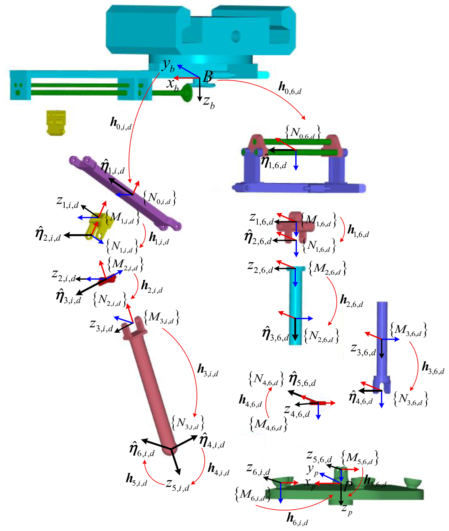
In this section, the error model of the 5PUS-PRPU parallel mechanism is established under the assumption that the 5PRR parallel mechanism is error-free. Figure 4 presents the local joint coordinate frames for the ith PUS and PRPU limbs. Therefore, according to the method introduced above, the error model of the moving platform represented by the kinematic parameter errors of the PUS limbs and PRPU limb can be obtained as
where represents the reciprocal system of the 5PUS-PRPU parallel mechanism, and (i=1–5) and represent the reciprocal screws of the ith PUS limb and the middle PRPU limb, respectively. , and δpi,d (i=1–5) and δp6,d represent the kinematic error vectors of the ith PUS limb and the PRPU limb, respectively. , (i=1–5), and . The matrices, such as Πi,d, Φi,d, , Π6,d, Φ6,d, , δpi,d, and δp6,d mentioned above, are given as
3.2.3 Error modeling of the 5-DOF 5PRR+5PUS-PRPU hybrid mechanism
By combining the error models in Eqs. (15) and (16), the overall error model of the 5-DOF 5PRR+5PUS-PRPU hybrid mechanism expressed by all the kinematic errors of the PRR, PUS, and PRPU limbs can be directly obtained as
where , and Ξ1,u and Ξ6,u represent the adjoint transformations from the fixed platform to the actuated P joint of the first PUS limb and the first P joint of the PRPU passive limb, respectively. Moreover, , Ω′, Ξ1,u, and Ξ6,u are given as
In this section, numerical simulations of kinematic calibration are conducted to verify the correctness of the established error models in Sect. 3. A comparative analysis of the traditional inverse kinematics and POE-formula-based error modeling methods is also performed to demonstrate the effectiveness of the proposed POE error model. First, the forward kinematic search method and the kinematic calibration simulation process of the hybrid mechanism are given in detail. Subsequently, kinematic calibration simulations are carried out for the 5-DOF hybrid mechanism under identical-motion conditions based on the two error models.
4.1 Process of kinematic calibration simulations
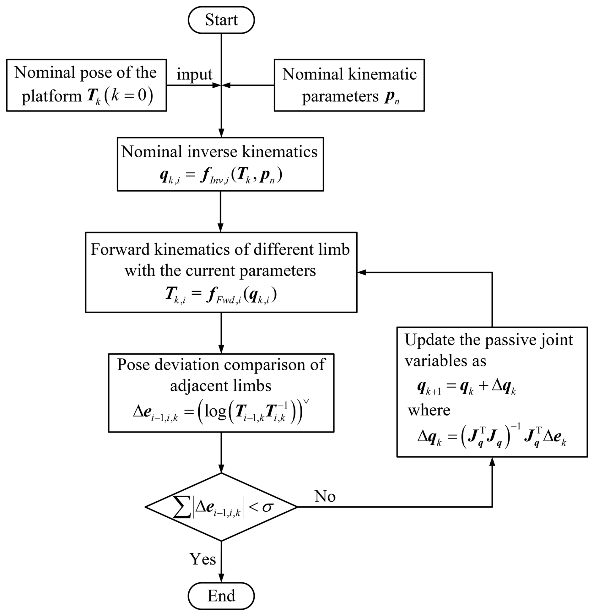
The identification of the kinematic error parameters has an important role in the kinematic calibration, and the calculation of the actual motions of passive joints under current kinematic parameters is key to the identification process of error parameters. In this section, a numerical searching method for computing the forward and inverse kinematics of the hybrid mechanism during the kinematic calibration process is introduced. In this method, the driving joints' actual displacements and the moving platform's nominal pose are both known. Then, the process of the numerical searching method can be described as follows:
-
Based on the nominal pose of the moving platform, the nominal motions of the passive joints are first calculated and used as initial values. Using these initial values and the current kinematic parameters, the forward kinematics of each limb and the deviations between the end poses of the limbs are obtained.
-
The termination of the numerical search algorithm depends on these deviations. If the deviations do not meet the judgment criteria, the motions of the passive joints are updated using a compensation formula for the next iteration. The iterative process terminates when the criteria are satisfied.
-
Finally, the actual motions of the passive joints and the corresponding pose of the moving platform under the current kinematic error parameters are obtained.
The compensation formula, which is used for updating the passive joints' motions of the PRR, PUS, and PRPU limbs, can be expressed uniformly as
where and are the screw coordinates of the end pose errors between the i−1th and ith limbs in the kth iteration, and and Ti,k represent the corresponding end poses of the limbs which are calculated by the i−1th and ith limbs. The transformation matrix Jq is given as
where represents the corresponding Jacobian matrix of the passive joints of the ith limb. The iterative process of kinematic searching will be terminated when the value of is smaller than the given threshold. As for and , i takes a value in the ranges of 2–5 and 2–6 for the 5PRR and 5PUS-PRPU parallel manipulators, respectively.
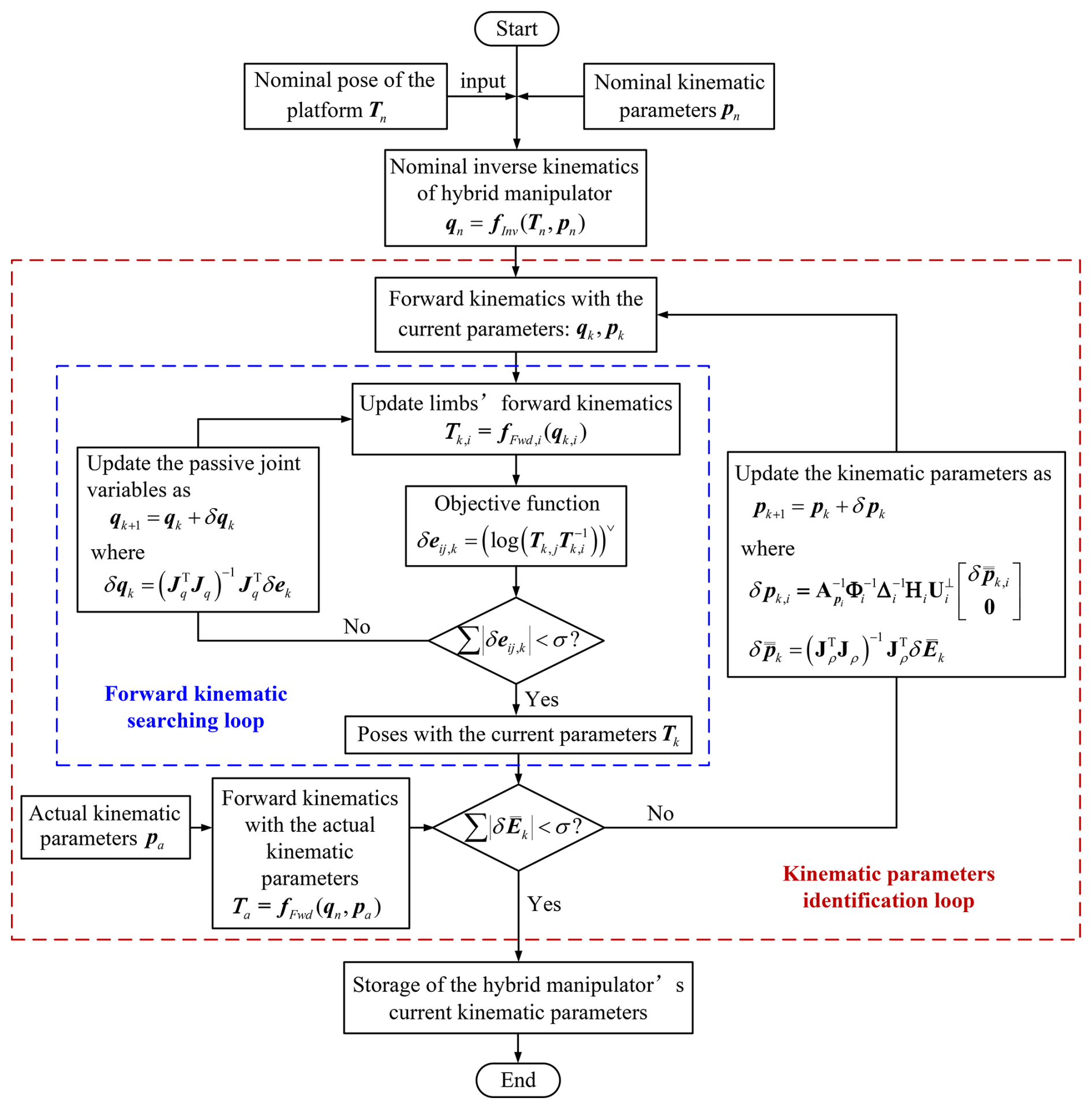
The flowchart of the forward kinematic search method for kinematic calibration simulations is shown in Fig. 5. After the above numerical iteration for forward kinematics, the identification analysis of the kinematic error parameters is carried out in the subsequent section. During parameter identification, the pose of the moving platform obtained under the current kinematic parameters is compared with the actual pose. If the deviation between the two poses meets the judgment criteria, the current kinematic parameters are stored; otherwise, the kinematic parameters are updated based on the established error model for the next iteration. Finally, the actual kinematic error parameters and the mean position and orientation errors of the moving platform after simulation analysis are obtained, verifying the correctness of the error model and improving the motion accuracy of the moving platform.
For the identification analysis of the manipulator, a sufficient number of end-effector poses must be measured and compared with the calculated poses to ensure that all kinematic error parameters are included in the identification model. Thus, the error analysis model for the 5-DOF hybrid manipulators can be expressed as
where is the pseudo-inverse of the identification matrix , and the subscript n represents the nth group configuration of the manipulator. denotes the vector containing the n group error vectors of the hybrid manipulator; () is the deviation of the end effector's actual pose with respect to the calculated poses at the configuration t; and Ta,t and Tc,t are the actual and calculated poses of the end effector, which can be obtained by the actual and current kinematic parameters of the limbs, respectively.
Then, the compensation formula used for updating the kinematic error parameters of the ith limb can be derived based on the established error models of these two parallel manipulators, which is shown as
where denotes the independent error vector of the ith limb, which can be obtained from in Eq. (19), and the orthogonal matrices Hi and will be updated in accordance with the current kinematic parameters of the corresponding limbs.
Finally, based on the identification analysis of kinematic error parameters for the 5PRR and 5PUS-PRPU parallel manipulators, a flow diagram of the parameter identification and kinematic calibration simulation of the 5-DOF hybrid manipulator is illustrated in Fig. 6.
4.2 Definition of nominal kinematic parameters
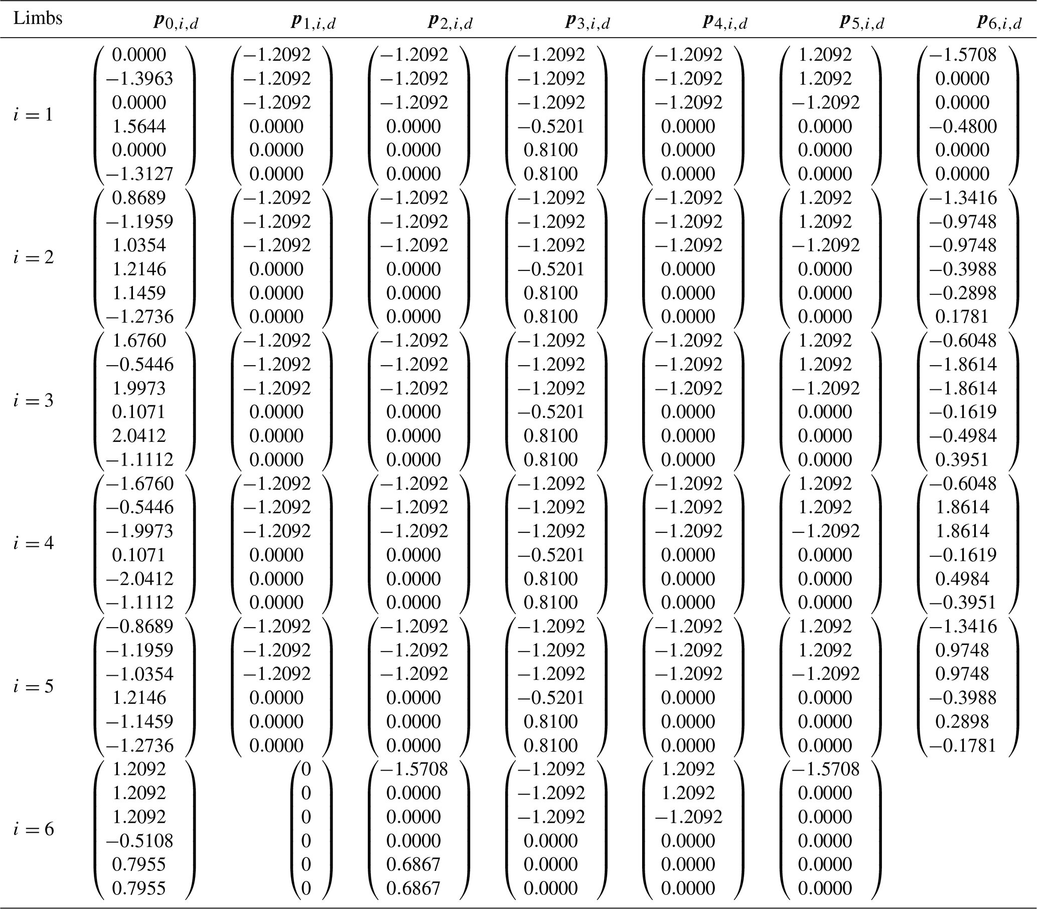
To simulate the real error environment of the hybrid manipulator, the nominal kinematic parameters and corresponding errors should first be defined to obtain the actual kinematic parameters of the manipulator. According to the dimensional synthesis analysis of the hybrid manipulator in Yang et al. (2021), the optimal structural parameters of the hybrid manipulator have been obtained and are shown as follows: l1=1.480 m, l2=1.420 m, rm=0.700 m, rp=0.490 m, and d=0.200 m. Tables 1 and 2 give the nominal kinematic parameters of the 5PRR and 5PUS-PRPU parallel mechanisms, respectively. In the process of numerical simulations, the actual kinematic parameters of the manipulator are defined on the basis of the nominal ones. Namely, the corresponding error parameters of each kinematic parameter are randomly selected within the range of the nominal kinematic parameters plus rad m−1. To fully investigate the pose errors of the moving platform, the configurations including the different positions of the variable-structure 5PRR parallel mechanism will be considered in the numerical simulations. According to the optimization results, it can be known that the value of θ takes , , , , and , which means the pose range of the moving platform will change with different values of θ.
Table 1Nominal kinematic parameters of the 5PRR parallel mechanism.
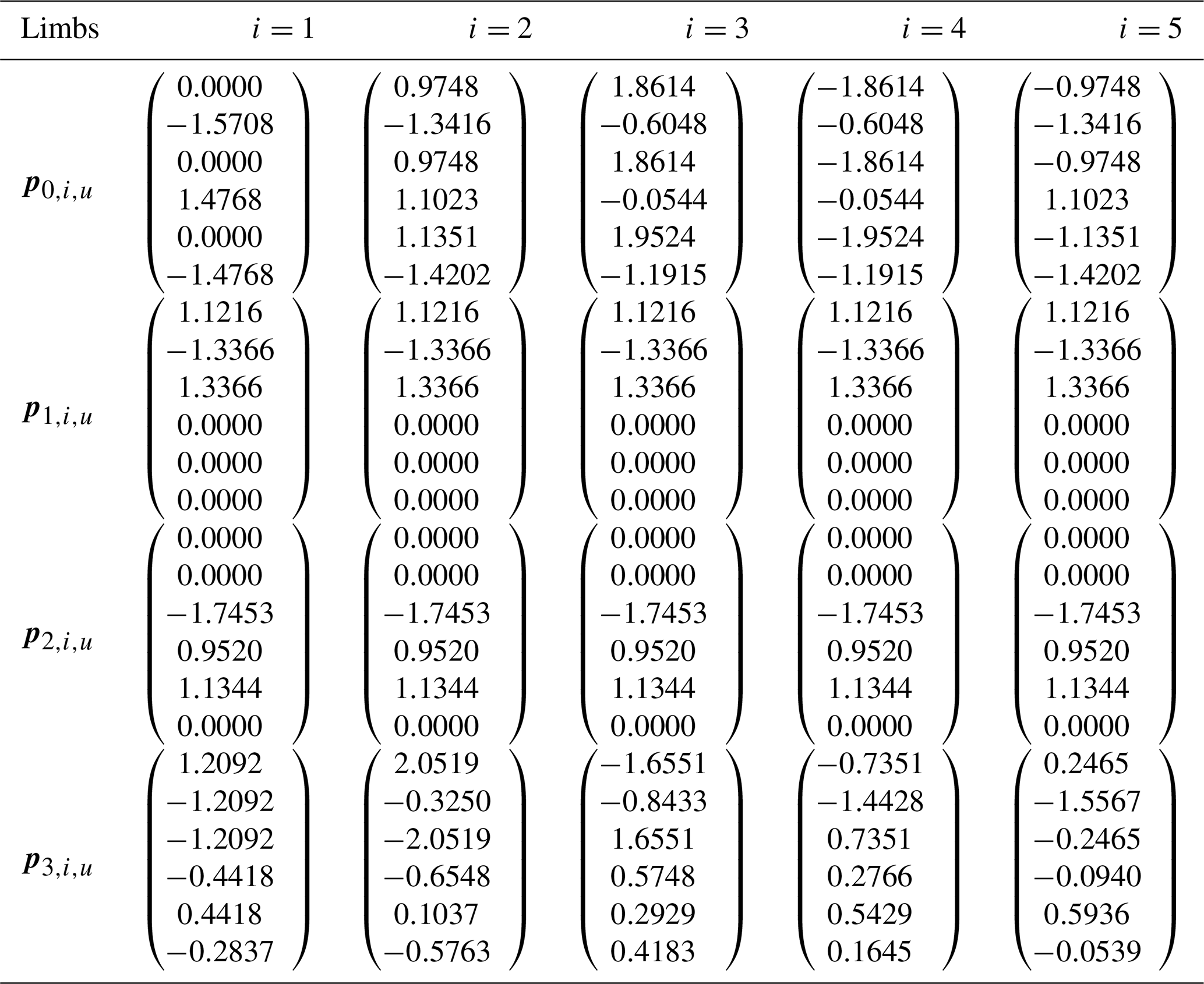
Table 2Nominal kinematic parameters of the 5PUS-PRPU parallel mechanism.
4.3 Comparison of calibration simulations
In this section, numerical simulations of kinematic calibration are performed to verify the correctness of the error models established in Sect. 3. A comparative analysis of the traditional inverse kinematics and the POE formula error modeling methods is carried out through kinematic calibration simulations of the 5-DOF hybrid manipulator. Before the numerical simulations, the following aspects need to be explained:
-
In addition to the nominal and actual kinematic parameters, the pose of the moving platform used for error simulation analysis and result evaluation must be defined. Based on the given pose and nominal kinematic parameters, the displacements of the passive joints of all limbs are calculated via inverse kinematics.
-
The poses of the moving platform used for error analysis and result evaluation are obtained from the actual kinematic parameters and joint motions, simulating the actual pose of the moving platform measured by measuring instruments in real-world environments.
-
Identification analysis of kinematic error parameters is performed based on the nominal and actual poses of the moving platform obtained above, ultimately yielding the actual kinematic parameters and the corresponding end-effector poses.
Furthermore, the poses of the moving platform defined for error result evaluation are also used to assess the absolute positioning accuracy under the current kinematic parameters. During the numerical simulations, the poses defined for error analysis are primarily used for identification computations, while the poses defined for result evaluation are employed to assess the effect of each iteration. Specifically, the forward kinematics of the hybrid manipulator are computed based on the updated kinematic parameters, and the current pose of the moving platform is obtained and compared with the actual pose. Notably, the evaluation process is independent of the identification calculation process of the kinematic error parameters.
In the kinematic calibration simulations, the position and orientation error formulas describing the positioning accuracy of the 5-DOF hybrid manipulator are defined as
where and represent the mean errors of the position and orientation used for verifying the results of the error simulation analysis, and nveri is the number of corresponding mechanism configurations. pa,i and Ra,i denote the actual position and orientation of the moving platform, and pn,i and Rn,i are the moving platform's theoretical position and orientation under the current kinematic error parameters.
To better compare the effectiveness of kinematic calibration, numerical simulations based on these two error modeling methods are conducted under identical parameter settings. It is also assumed that the 5PRR parallel mechanism is error-free and that no noise disturbances are considered in the numerical simulations. From the error model of the 5-DOF hybrid manipulator in Eq. (17), it can be seen that there are 246 identifiable kinematic parameters in the 5PUS-PRPU parallel mechanism. Since each configuration can obtain 6 constraint equations, at least 41 configurations are needed to meet the requirements of parameter identification analysis. To obtain optimal simulation results, the number of configurations used for the simulation should exceed the theoretical number and cover the entire workspace as much as possible.
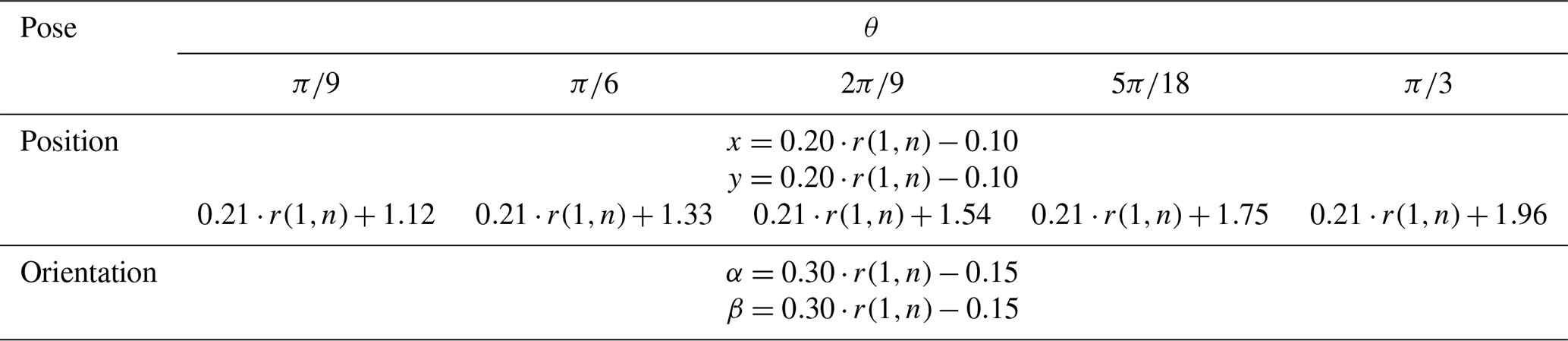
Therefore, 100 configurations are randomly generated within the reachable workspace of the moving platform, which are used for the kinematic calibration in the comparison analysis. Meanwhile, another 100 configurations will also be given to evaluate the results of the calibration. Table 3 gives the random pose ranges of the moving platform for different values of θ, where r(1,n) represents the n groups of values randomly generated within the range [0,1].
Table 3The randomly generated n sets of configurations with different values of θ.
Based on the two error modeling methods, the mean position and orientation errors of the moving platform, calculated using the 100 defined calibration configurations, are illustrated in Fig. 7. The left bars represent the analysis results based on the inverse kinematics error model, and the right ones are the corresponding results of the POE formula error model. From the iteration results, it can be seen that they can both converge rapidly to a stable value based on the different modeling methods. However, in terms of positioning accuracy, the final mean position and orientation errors of the moving platform obtained by the POE formula error model are 2 orders of magnitude and 1 order of magnitude lower than those obtained by the inverse kinematics method, respectively. The main reason is that there are 246 kinematic error parameters in the error model based on the POE formula, which can be independently identified, and there are only 50 identifiable kinematic parameters in the error model built by the inverse kinematics method. The calibration results verify the correctness of the error models established in Sect. 3 and indicate that the error model based on the POE method is more comprehensive than that obtained by the traditional inverse kinematics method.
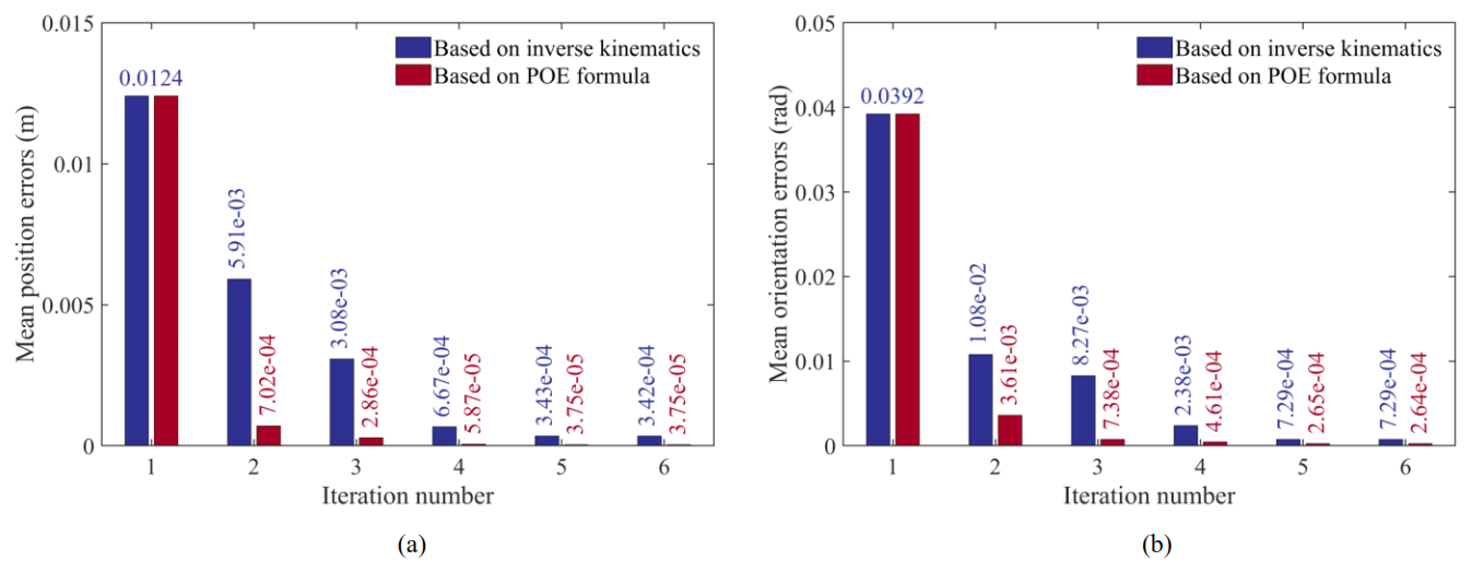
Figure 7Comparisons of mean pose errors of the moving platform in the process of iteration identification based on different modeling methods: (a) mean position errors and (b) mean orientation errors.
Following the comparative analysis, kinematic calibration simulations based on the two methods are conducted for the 5-DOF hybrid manipulator when θ takes , , , , and . For different positions of the 5PRR variable-structure parallel manipulator, 80 poses of the moving platform are defined for each, with the random pose generation method referring to Table 3. Then, Figs. 8 and 9 illustrate the moving platform's mean position and orientation errors of the corresponding methods during the iterative process with different values of θ, respectively. It can be observed that the moving platform exhibits different initial mean position and orientation errors under the nominal kinematic parameters for different values of θ.
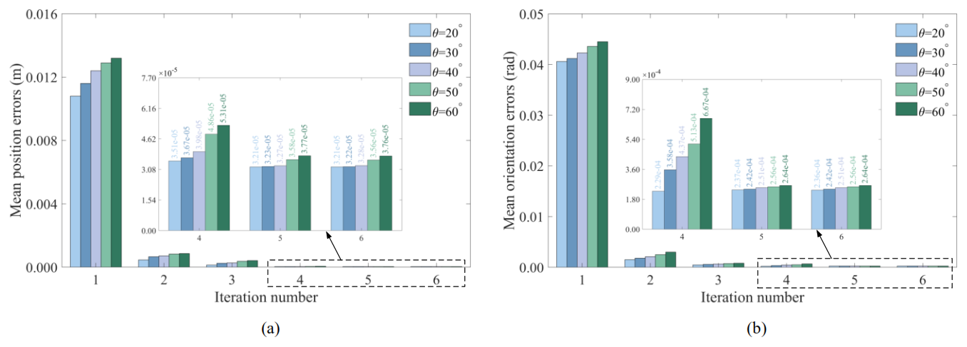
Figure 8Moving platform's mean position and orientation errors with different values of θ based on the POE formula method: (a) mean position errors and (b) mean orientation errors.
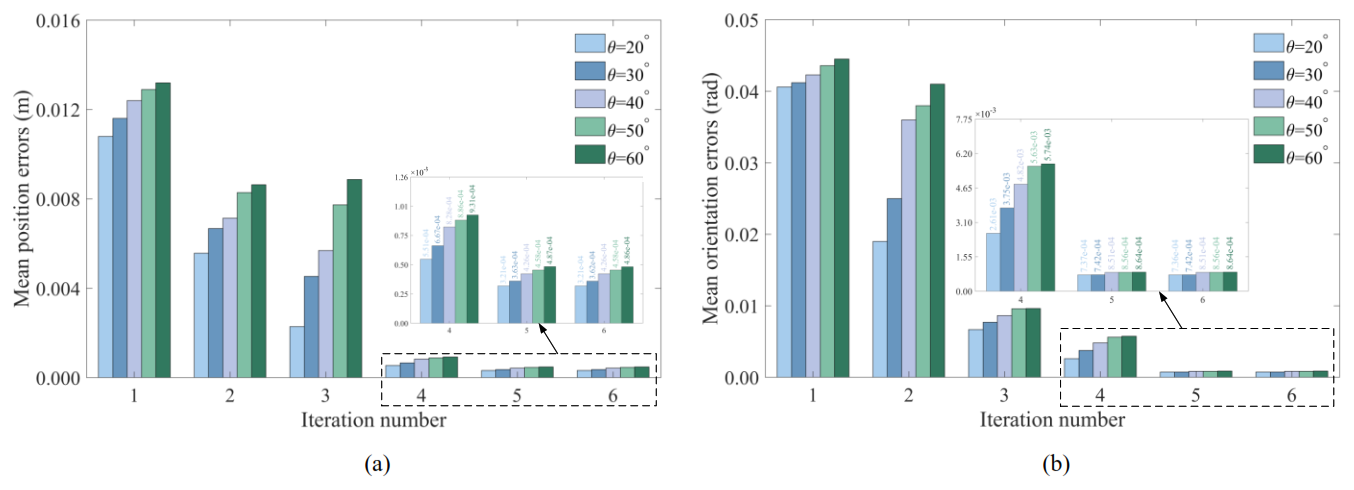
Figure 9Moving platform's mean position and orientation errors with different values of θ based on the inverse kinematics method: (a) mean position errors and (b) mean orientation errors.
However, the calibration results show that during the parameter iteration process, the mean position and orientation errors obtained via the error model based on the traditional method are larger than those obtained via the error model based on the POE formula. Moreover, the mean position and orientation errors are significantly improved in the second iteration for the POE-formula-based error model. This indicates that the 246 error parameters of the 5-DOF hybrid manipulator can compensate for all pose errors of the moving platform, verifying the effectiveness and completeness of the error model established for the 5-DOF hybrid manipulator using the POE formula method.
To further compare the two modeling methods, Fig. 10 plots the position and orientation errors of the moving platform for each evaluation configuration after kinematic calibration using the inverse kinematics and POE formula methods. For most evaluation configurations, the error results after kinematic calibration using the POE formula method are significantly superior to those based on the inverse kinematics method. In Fig. 10, the maximum position and orientation errors based on the inverse kinematics method are m and rad, while the values based on the POE formula method are m and rad, respectively. The results further confirm the effectiveness of the proposed POE error modeling method for improving positioning accuracy.
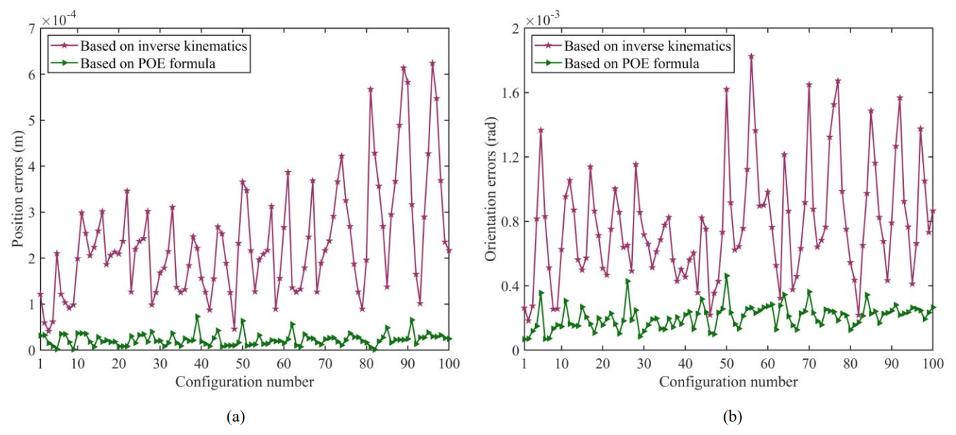
Figure 10Pose errors of 100 sets of evaluation configurations after kinematic calibration based on different methods: (a) position errors and (b) orientation errors.
Additionally, due to the larger number of error parameters in the proposed kinematic calibration error model, the computational cost is inevitably higher than that of the inverse kinematics method, and the control strategy is more complex. To quantitatively evaluate the computational efficiency differences between the POE formula method and the traditional inverse kinematics (INK) method, a comparative analysis was conducted using the same hardware platform and kinematic calibration simulation data. The calibration iteration number was set to 6 for both methods, and all results were averaged over 10 repeated simulations to ensure the statistical reliability of the data. The key computational efficiency indices and calibration accuracy results of the two methods are summarized in Table 4.
Table 4Comparison of computational efficiency and calibration accuracy between POE and inverse kinematics methods.
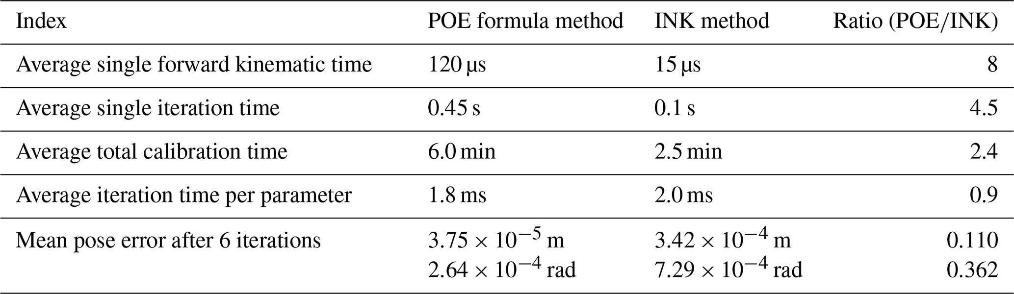
Based on the comparison results, the computational efficiency characteristics and accuracy–efficiency trade-off of the two methods are summarized as follows:
-
The computational time gap between the two methods is essentially attributed to the difference in parameter scale (246 for POE vs. 50 for INK) and the complexity of the modeling logic, rather than the low computational efficiency of individual parameters in the POE formula method. The POE formula method realizes the refined characterization of geometric errors across all kinematic chains of the hybrid manipulator by virtue of its high-dimensional parameter model, which inevitably introduces additional computational overhead from screw theory operations and high-dimensional Jacobian matrix calculations. In contrast, the inverse kinematics method simplifies the computational process at the cost of the integrity of error modeling, leading to lower computational time but insufficient error characterization capability.
-
The average total calibration time of the POE method is 2.4 times that of the inverse kinematics method, while the POE method exhibits remarkably superior calibration performance: the mean position and orientation errors after calibration are reduced by 89.04 % and 63.79 % compared with the inverse kinematics method, respectively. This result conforms to the well-recognized engineering principle that high-dimensional modeling is accompanied by higher computational costs and higher-precision calibration effects and fully verifies the rationality of the POE method's trade-off between computational efficiency and calibration accuracy.
-
The computational time of the POE method has considerable optimization potential in practical engineering applications. Strategies such as multi-core parallelization and vectorization of screw theory operations can effectively reduce the computational overhead of the POE model, while its inherent advantage in calibration accuracy remains uncompromised. This provides a feasible technical insight for the efficient engineering-oriented application of the POE method in the kinematic calibration of high-degree-of-freedom hybrid manipulators.
The above quantitative comparison clarifies the computational efficiency differences between the two methods and their underlying causes and further verifies the superiority of the POE method in the accuracy–efficiency trade-off, which enriches the performance verification results of the proposed POE error model and calibration method for hybrid manipulators.
This paper focuses on the 5-DOF 5PRR+5PUS-PRPU variable-structure hybrid manipulator as the research object. Kinematic calibration simulations are conducted to compare the traditional inverse kinematics and POE-formula-based error modeling methods, revealing that the POE-derived error model is more comprehensive and effective. Furthermore, kinematic calibration simulations on 100 configurations demonstrate that the mean pose errors of the moving platform converge stably after 6 iterations, with mean position and orientation errors reduced by 89.04 % and 63.79 %, respectively, compared to the traditional inverse kinematics approach. These findings confirm the correctness and validity of both the proposed POE-formula-based error modeling method and the kinematic calibration simulation method. Notably, the proposed modeling method is applicable to error modeling and analysis of most parallel mechanisms, providing new approaches and insights for the kinematic calibration of such mechanisms.
For a given pose matrix T∈SE(3), Ad(T) denotes the adjoint transformation of T and can be written as
The matrix represents the transformation of the kinematic parameter to the pose errors, which can be expressed as
Herein, the values of coefficients , , , and are shown as
where , and and denote the abbreviation for sin (χj,i) and cos (χj,i), respectively. is the adjoint matrix of , which can be written as
and represent the antisymmetric matrices of the three-dimensional vectors ωj,i and vj,i with the following expressions:
The data that support the findings of this study are available from the corresponding author upon reasonable request.
HY and LB proposed conceptualization, methodology, and investigation; HY and ZJ designed the simulations, and XL carried them out; HY and ZL developed the software and validation; HY and LB contributed to the writing of the paper (original draft); and HY, LB, and ZJ provided financial support. All authors have read and agreed to the published version of the paper.
The contact author has declared that none of the authors has any competing interests.
Publisher's note: Copernicus Publications remains neutral with regard to jurisdictional claims made in the text, published maps, institutional affiliations, or any other geographical representation in this paper. The authors bear the ultimate responsibility for providing appropriate place names. Views expressed in the text are those of the authors and do not necessarily reflect the views of the publisher.
This study is supported by the National Natural Science Foundation of China (grant nos. 12572002 and 52175452) and the R&D Program of the Beijing Municipal Education Commission (grant no. KM202311232022).
This paper was edited by Pengyuan Zhao and reviewed by Yang Zhang, Fuqun Zhao, and one anonymous referee.
Chen, G. L., Wang, H., and Lin, Z. Q.: Determination of the Identifiable Parameters in Robot Calibration Based on the POE Formula, IEEE Trans. Robot., 30, 1066–1077, https://doi.org/10.1109/TRO.2014.2319560, 2014.
Chen, G. L., Kong, L. Y., Li, Q. C., Wang, H., and Lin, Z. Q.: Complete, minimal and continuous error models for the kinematic calibration of parallel manipulators based on POE formula, Mech. Mach. Theory, 121, 844–856, https://doi.org/10.1016/j.mechmachtheory.2017.11.003, 2018.
Daney, D.: Kinematic calibration of the Gough Platform, Robotica, 21, 677–690, https://doi.org/10.1017/S0263574703005083, 2003.
Feng, J., Gao, F., and Zhao, X.: Calibration of a six-DOF parallel manipulator for chromosome dissection, Proceedings of the Institution of Mechanical Engineers, Proc. Inst. Mech. Eng. C: J. Mech. Eng. Sci., 226, 1084–1096, https://doi.org/10.1177/0954406211418420, 2012.
Frisoli, A., Solazzi, M., Pellegrinetti, D., and Bergamasco, M.: A new screw theory method for the estimation of position accuracy in spatial parallel manipulators with revolute joint clearances, Mech. Mach. Theory, 46, 1929–1949, https://doi.org/10.1016/j.mechmachtheory.2011.07.004, 2011.
Huang, T., Dong, C. L., Liu, H. T., Sun, T., and Chetwynd, D. G.: A simple and visually orientated approach for type synthesis of over-constrained 1T2R parallel mechanisms, Robotica, 37, 1161–1173, https://doi.org/10.1017/s0263574718000395, 2019.
Jiang, Y., Li, T. M., Wang, L. P., and Chen, F. F.: Kinematic error modeling and identification of the over-constrained parallel kinematic machine, Robot. Comput. Integr. Manuf., 49, 105–119, https://doi.org/10.1016/j.rcim.2017.06.001, 2018.
Jiang, Z. X., Huang, M., Tang, X. Q., and Guo, Y. X.: A new calibration method for joint-dependent geometric errors of industrial robot based on multiple identification spaces, Robot. Comput. Integr. Manuf., 71, 102175, https://doi.org/10.1016/j.rcim.2021.102175, 2021.
Kong, L. Y., Chen, G. L., Zhang, Z., and Wang, H.: Kinematic calibration and investigation of the influence of universal joint errors on accuracy improvement for a 3-DOF parallel manipulator, Robot. Comput. Integr. Manuf., 49, 388–397, https://doi.org/10.1016/j.rcim.2017.08.002, 2018.
Kong, L. Y., Chen, G. L., Wang, H., Huang, G. Y., and Zhang, D.: Kinematic calibration of a 3-PRRU parallel manipulator based on the complete, minimal and continuous error model, Robot. Comput. Integr. Manuf., 71, 102158, https://doi.org/10.1016/j.rcim.2021.102158, 2021.
Li, H., Chen, W., Yi, L., Leng, C., and Wu, H.: Design, modeling and manufacture error identification of a new 6-degree-of-freedom (6-DOF) compliant parallel manipulator, Mech. Sci., 16, 143–156, https://doi.org/10.5194/ms-16-143-2025, 2025.
Liang, S., Wang, L. B., Fang, Q., and Wei, Y. D.: Kinematic calibration of redundantly actuated distributed parallel manipulators based on local POE formula and ridge estimation method, Precis. Eng., 97, 879–889, https://doi.org/10.1016/j.precisioneng.2025.11.001, 2026.
Liu, H. T., Huang, T., and Chetwynd, D. G.: A general approach for geometric error modeling of lower mobility parallel manipulators, J. Mech. Robot., 3, 021013, https://doi.org/10.1115/1.4003845, 2011.
Majarena, A. C., Santolaria, J., Samper, D., and Aguilar, J. J.: An overview of kinematic and calibration models using internal/external sensors or constraints to improve the behavior of spatial parallel mechanisms, Sensors, 10, 10256–10297, https://doi.org/10.3390/s101110256, 2010.
Maurine, P. and Dombre, E.: A calibration procedure for the parallel robot Delta 4, in: Proceedings of IEEE International Conference on Robotics and Automation, Minneapolis, USA, 22–28 April, 975–980, https://doi.org/10.1109/ROBOT.1996.506835, 1996.
Ni, Y. B., Shao, C. Y., Zhang, B., and Guo, W. X.: Error modeling and tolerance design of a parallel manipulator with full-circle rotation, Adv. Mech. Eng., 8, https://doi.org/10.1177/1687814016649300, 2016.
Okamura, K. and Park, F. C.: Kinematic calibration using the product of exponential formula, Robotica, 14, 415–421, https://doi.org/10.1017/S0263574700019810, 1996.
Verner, M., Xi, F. F., and Mechefske, C.: Optimal calibration of parallel kinematic machines, J. Mech. Des., 127, 62–69, https://doi.org/10.1115/1.1828461, 2005.
Wang, Y., Dong, M. J., Zuo, G. Y., Li, J. F., Ju, J., Ma, Q. H., and Zuo, S. P.: POE-based error modeling and multiple plane constraint-based parameter identification for the kinematic calibration of a 4-UPS/SPR parallel external fixator, Appl. Math. Model., 133, 394–413, https://doi.org/10.1016/j.apm.2024.05.031, 2024.
Wu, H. Y., Kong, L. Y., Li, Q. C., Wang, H., and Chen, G. L.: A comparative study on kinematic calibration for a 3-DOF parallel manipulator using the complete-minimal, inverse-kinematic and geometric-constraint error models, Chin. J. Mech. Eng., 36, 121, https://doi.org/10.1186/s10033-023-00940-3, 2023.
Wu, H. Y., Liang, Z. K., Zhang, Z., Kong, L. Y., Wang, H., and Chen, G. L.: Kinetostatics modeling and elasto-geometrical calibration of overconstrained parallel manipulators, Mech. Mach. Theory, 191, 105490, https://doi.org/10.1016/j.mechmachtheory.2023.105490, 2024.
Xu, D. L., Guo, S., Zhao, F. Q., and Jin, X. D.: Design and analysis of a bimanual parallel dexterous hand with cooperative manipulation capability, J. Mech. Robot., 17, 061014, https://doi.org/10.1115/1.4067481, 2025.
Yang, H., Fang, H. R., Fang, Y. F., and Li, X. Y.: Dimensional synthesis of a novel 5-DOF reconfigurable hybrid perfusion manipulator for large-scale spherical honeycomb perfusion, Front. Mech. Eng., 16, 46–60, https://doi.org/10.1007/s11465-020-0606-2, 2021.
Yu, D. W., Zhao, Q. Q., Guo, J. K., Chen, F. F., and Hong, J.: Accuracy analysis of spatial overconstrained extendible support structures considering geometric errors, joint clearances and link flexibility, Aerosp. Sci. Technol., 119, 107098, https://doi.org/10.1016/j.ast.2021.107098, 2021.
Yuan, X., Kong, L. Y, Zhang, Z., Huang, G. Y., Xie, A. H., and Chen, G. L.: Analysis of the influence of passive joints on kinematic calibration of parallel manipulators based on complete error model, Precis. Eng., 90, 56–70, https://doi.org/10.1016/j.precisioneng.2024.08.002, 2024.
Zhang, J. F., Chen, Q. H., Wu, C. Y., and Li, Q. C.: Kinematic calibration of a 2-DOF translational parallel manipulator, Adv. Robot., 28, 707–714, https://doi.org/10.1080/01691864.2014.888374, 2014.
Zhang, Y., Xu, P., and Li, B.: Structure derivative design, network, and kinematic analysis of a class of two-dimensional deployable mechanisms for aerospace platforms, Mech. Mach. Theory, 185, 105314, https://doi.org/10.1016/j.mechmachtheory.2023.105314, 2023.
Zhang, Y., Wang, W. X., Kang, X., and Li, B.: Design, analysis, and experimentation of deployable multi-closed-loop truss modules for aerospace platforms, Mech. Mach. Theory, 205, 105897, https://doi.org/10.1016/j.mechmachtheory.2024.105897, 2025.
Zhao, F. Q., Xu, D. L., Jin, X. D., Ding, X. L., Guo, S., Xu, K., and Fang, Y. F.: In-hand manipulation using a 3-PRS-finger-based parallel dexterous hand with bidirectional pinching capability, Mech. Mach. Theory, 192, 105553, https://doi.org/10.1016/j.mechmachtheory.2023.105553, 2024.
Zhou, Z. Z., Qu, H. B., Li, X., Hu, B. Q., and Guo, S.: Error sensitivity analysis of a 1T2R kinematically redundant parallel mechanism with closed-loop chain, J. Mech. Des., 147, 053301, https://doi.org/10.1115/1.4066747, 2025.