the Creative Commons Attribution 4.0 License.
the Creative Commons Attribution 4.0 License.
 | 05 May 2026
A variable stiffness omnidirectional chain based on positive-pressure fiber jamming
Shuai Zhang
Jiantao Yao
This paper presents the design, analytical modeling, and prototype-level experimental assessment of a variable stiffness omnidirectional chain (VSOC) based on positive-pressure fiber jamming. To address the intrinsic pressure limitation (∼ 1 atm) of conventional vacuum-based jamming, an internal inflatable bladder is used to compact a fiber bundle in a rigid chain link, thereby providing a broader tunable pressure range for stiffness modulation. A mechanics-based model is developed for a fiber jamming rod under bending, defining the jamming, transition, and slipping states; deriving the critical shear forces associated with state transitions; and introducing a pressure-dependent equivalent area moment of inertia to describe the variation in stiffness. This framework is then adapted to the two primary bending modes of VSOC. Three-point bending experiments over 0–300 kPa are used to evaluate whether the model can capture the observed pressure-dependent behavior of the present prototype. Effective parameters, including an inter-fiber friction coefficient (μ = 0.3665) and an effective fiber modulus (E = 4.85 GPa), identified from the jamming pressure p = 0 kPa bending response, are used in the present structure-level model. Within the tested pressure range, the results indicate that critical loads and slipping state stiffness increase approximately linearly with jamming pressure, whereas jamming state stiffness is comparatively insensitive to pressure and is primarily governed by geometry. This work bridges design, theory, and experiment to develop a high-performance variable stiffness structure with significant potential for soft robotics and wearable devices.
- Article
(4122 KB) - Full-text XML
- BibTeX
- EndNote


The field of soft robotics, characterized by the use of compliant materials, has enabled machines to operate safely and adaptively in unstructured environments, extending their application from industrial settings to interactive and service domains (Laschi et al., 2016). Recent reviews further show that advances in soft robotics depend not only on structural and material innovation but also on modeling, planning, and control methods that can handle strong nonlinearity and continuous deformation (Yu et al., 2026). A fundamental challenge in this field is the inherent trade-off between compliance and load-bearing capacity, which has driven significant research interest in mechanisms for controllable stiffness variation (Manti et al., 2016). Such capability allows a robotic structure to interact gently, using its inherent softness while also augmenting its force exertion when required (Wang et al., 2018).
Among various variable stiffness technologies, jamming-based structures have attracted considerable attention due to their simple construction, rapid reversibility, and significant stiffness contrast (Fitzgerald et al., 2020; Liu and Nagel, 1998). The jamming phenomenon refers to the transition of confined discrete elements (granules, layers, or fibers) from a fluid-like low-stiffness stage to a solid-like high-stiffness stage under applied stress (Liu and Nagel, 1998; Narang et al., 2020). This principle has been successfully implemented in three primary forms: granular jamming structures (GJSs), layer jamming structures (LJSs), and fiber jamming structures (FJSs) (Aktaş et al., 2021). LJSs and FJSs were first introduced as controllable impedance elements for wearable devices (Tabata et al., 2000; Kawamura et al., 2002) and have since found applications in areas such as compliant grasping (Bai et al., 2022; Narang et al., 2018a), haptic feedback (Jadhav et al., 2022; Kawamura et al., 2003), and tunable damping (Narang et al., 2018b; Pinskier et al., 2022; Yang et al., 2021). GJSs, popularized in soft robotics for grippers and morphing structures (Brown et al., 2010; Steltz et al., 2009), also represent a major branch of this technology.
Recent studies further show that variable stiffness design is no longer limited to conventional vacuum-driven jamming. Positive-pressure and internally pressurized jamming strategies have been explored across several embodiment levels. In granular jamming, positive pressure has been used to build controllable organ phantoms with tunable local stiffness and morphology for abdominal palpation simulation (He et al., 2018), and positive-pressure jamming structures with self-locking joints have also been developed for wearable robots to enlarge the achievable stiffness range beyond the vacuum limit (Liu et al., 2021). In layer jamming systems, positive-pressure concepts have enabled soft grippers with a higher payload and large stiffness variation (Crowley et al., 2022) to be embedded into inflated beam robots to selectively activate joints for reconfiguration (Do et al., 2024). These have been combined with layered or hybrid architectures to enhance load-bearing performance in bio-inspired shells and amphibious morphing limbs (Arleo et al., 2023; Sun et al., 2024). Positive-pressure fiber jamming has also appeared in modular soft arms such as VARISA, where it contributes to multidirectional actuation and structure-level stiffness tuning (Arleo and Cianchetti, 2024).
This broader literature is important because it clarifies that the present work should not be framed simply as a replacement of vacuum by positive pressure. Existing studies suggest that positive-pressure jamming can improve load capacity, usable pressure range, and architectural integration. The remaining gap is more specific: for fiber jamming structures, especially under bending, there is still a limited analytical description of how positive jamming pressure relates to state transitions, equivalent bending stiffness, and load-carrying behavior. Without this mechanics-level clarification, distinguishing the contribution of positive-pressure FJSs from other positive-pressure variable stiffness systems remains difficult.
Accurate mechanical models are crucial for the design and application of these jamming structures. This need for structure-specific modeling is also reflected in other compliant multi-element systems: for example, Wu et al. (2025) showed in a tether-net capture system that torsion, distributed contact, and deployment dynamics must be incorporated explicitly to describe the system response accurately. For LJSs, modeling efforts are relatively mature. A widely accepted model approximates bending stiffness based on the second moment of area of the cross-section, distinguishing between a monolithic solid state and a slipped state in which layers bend individually (Aktaş et al., 2021; Henke and Gerlach, 2014; Ibrahimi et al., 2021; Kawamura et al., 2003). More comprehensive analytical models based on Euler–Bernoulli beam theory have been developed to describe the stiffness, deformation, and transition criteria for both cantilever and three-point bending configurations of multi-layer beams (Caruso et al., 2022, 2023; Narang, 2018; Narang et al., 2018a). These models provide a strong foundation for LJS design.
In contrast, the analytical modeling of FJSs presents a greater challenge due to the complex three-dimensional interactions and rearrangements in a fiber bundle during deformation (Aktaş et al., 2021). Consequently, research has often relied on experimental characterization (Brancadoro et al., 2018, 2020) or on numerical methods, such as the finite-element-based homogenization approach developed by Vasios et al. (2019). While analytical models have been proposed for simpler tensile loading cases (Pinskier et al., 2022; Yang et al., 2021) or for specific fiber geometries treated as superposed beams (Jadhav et al., 2022), a comprehensive analytical framework for the bending behavior of FJSs – encompassing distinct stiffness states, transition criteria, and the role of jamming hydrostatic pressure – remains underdeveloped. Moreover, although recent positive-pressure jamming studies indicate the system-level potential of operating beyond the vacuum range, they do not yet isolate how positive jamming pressure affects bending-state evolution in a jammed fiber bundle. Furthermore, traditional FJSs typically employ vacuum pressure, which intrinsically limits the maximum achievable hydrostatic pressure to approximately one atmosphere, thereby constraining their ultimate stiffness and load capacity.
To address these gaps, this paper presents the design, analytical modeling, and experimental validation of a novel variable stiffness omnidirectional chain (VSOC) based on a positive-pressure fiber jamming structure. The contribution of this work is to couple a dedicated positive-pressure FJS architecture with a bending model formulated for that architecture. At the structural level, the proposed VSOC uses an internal inflatable bladder to compact the fiber bundle inside a rigid shell and a double-conical joint to enable multi-axis bending, thereby extending fiber jamming operation beyond the vacuum-pressure limit. At the theoretical level, the model distinguishes jamming, transition, and slipping states, derives pressure-dependent transition loads from inter-fiber friction, and represents stiffness evolution through an equivalent area moment of inertia adapted to the compacted cross-section and two bending modes of the prototype. The experimental objective is correspondingly limited: the present study examines whether this framework is interpretable and predictive for a single VSOC prototype, rather than claiming comprehensive validation over a wider parameter space. Systematic three-point bending experiments across 0–300 kPa are therefore used to assess whether the structure model pair can account for the measured pressure-dependent critical loads and stiffness changes under the tested conditions.
The remainder of this paper is organized as follows. Section 2 details the theoretical mechanics of a fiber jamming rod. Section 3 describes the design of the positive-pressure VSOC. Section 4 outlines the experimental setup and data processing methodology. Section 5 presents the results, including model validation and discussion. Finally, Sect. 6 concludes the paper.
This section establishes the theoretical framework for modeling the bending behavior of a fiber jamming rod. The model identifies distinct mechanical states governed by inter-fiber friction, derives the critical shear forces that demarcate transitions between these states, and formulates an equivalent area moment of inertia to describe the structure's variable bending stiffness.
2.1 Mechanical states and transition criteria
The mechanical response of a fiber jamming rod under bending is governed by the interaction between its constituent fibers, mediated by inter-fiber friction. Three distinct mechanical states are identified, as shown schematically in Fig. 1.
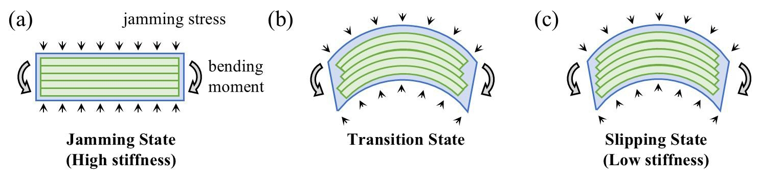
Figure 1Schematic of the three mechanical states in a fiber jamming rod under bending. (a) Jamming state resulting in a high-stiffness stage. (b) Transition state. (c) Slipping state resulting in a low-stiffness stage.
The jamming state describes the high-stiffness stage. Under sufficiently small external loads, the inter-fiber shear stress does not exceed the maximum static frictional stress. Consequently, no relative sliding occurs between adjacent fibers, compelling the entire bundle to deform as a monolithic solid. In this state, the structure exhibits its highest bending stiffness, and any induced deformation is fully recoverable upon unloading, as illustrated in Fig. 1a.
For the transition state, as the applied load increases, the internal shear stress at specific locations reaches the maximum static frictional resistance. Slip initiates at these critical interfaces, leading to a gradual decrease in overall structural stiffness. This intermediate state is depicted in Fig. 1b.
The slipping state describes the low-stiffness stage. When the applied load becomes sufficiently large, sliding occurs at all inter-fiber interfaces. In this regime, individual fibers are primarily free to bend about their own neutral axes, resulting in a significantly lower collective bending stiffness for the rod, as shown in Fig. 1c.
The transition between states is determined by comparing the internal shear stress distribution with the inter-fiber frictional resistance. According to the Euler–Bernoulli beam theory, the shear stress τ distribution across the section of the rod is parabolic. By the theorem of conjugate shear stresses, this longitudinal shear stress is equal to the inter-fiber frictional stress. Slip initiates at the location of maximum shear stress when its magnitude equals the maximum static frictional stress μp, where μ is the inter-fiber static friction coefficient and p is the jamming pressure (the hydrostatic pressure applied to maintain the jamming state). Therefore, the condition for the onset of slip, marking the transition from the jamming state, is given by
where Q is the transverse shear force on the cross-section and τmax(Q) is the maximum shear stress as a function of Q, determined by the cross-sectional geometry. Solving Eq. (1) yields the upper-bound shear force for the jamming state, denoted as QJ. This force can be expressed in a generalized form as
Here, k is a geometry-dependent coefficient with dimensions of area, determined by the section shape and the elasticity law.
When the applied load is large enough for the rod to enter the full-slipping state, the frictional stress is uniformly equal to μp at all interfaces. Consequently, the lower-bound shear force for the slipping state QS is simply the integral of this constant stress over the total cross-sectional area A:
For fiber jamming, A is the sum of the cross-sectional areas of all fibers.
2.2 Equivalent bending stiffness model
The bending stiffness of a beam is directly proportional to its area moment of inertia. To describe the variable bending stiffness of the fiber jamming rod, an equivalent area moment of inertia Ieq is defined, which transitions between the values corresponding to the jamming and slipping states.
In the jamming state, the absence of relative sliding forces causes all fibers to bend about the global neutral axis of the composite rod. The equivalent moment of inertia IJ is therefore calculated using the standard formula for a solid beam, integrating over the entire cross-sectional domain D of the fiber bundle:
where y is the distance from the area element dA to the neutral axis.
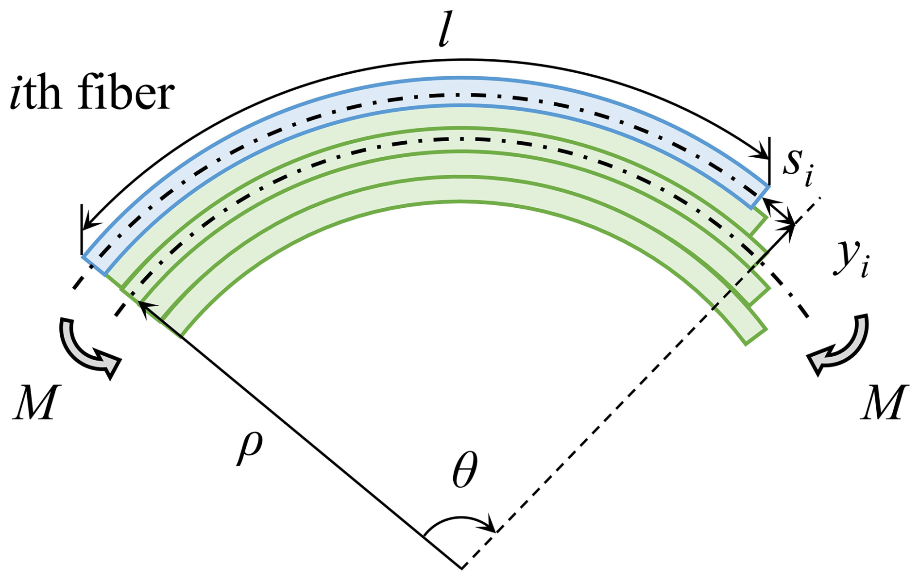
In the slipping state, fibers bend primarily about their individual centroids. However, inter-fiber friction provides an additional resistive moment that contributes to the overall bending stiffness. To derive the equivalent moment of inertia IS, a pure bending scenario under an applied moment M is considered for a bundle of N fibers, each of length l and with an individual area moment of inertia Ifib about its own centroidal axis. According to Euler–Bernoulli theory, the neutral axis of the bundle forms a circular arc with a radius of curvature ρ and a subtended angle θ, as illustrated in Fig. 2. Using the equivalent inertia IS, these geometric parameters are defined as and , where E denotes the effective fiber modulus used in the present structure-level model.
The work done by the applied moment is
This work is divided into two components: the elastic strain energy stored in the bent fibers and the energy dissipated by frictional sliding between fibers. The elastic strain energy in a single fiber is
where m is the moment borne by the corresponding fiber; assuming a uniform moment distribution among identical fibers, .
To compute the frictional dissipation, the relative slip distance between fibers must be determined. Under pure bending, the elongation deformation of an individual fiber contributes negligibly to the overall structural deformation compared to the inter-fiber slip; therefore, fiber elongation is neglected. For a fiber located at a distance yi from the bundle's neutral axis, the relative arc length difference si between this fiber and the neutral axis over length l can be obtained based on the geometric relationship, as shown in Fig. 2:
Substituting the expressions for θ and ρ leads to
The energy dissipated by friction due to this slip is
where c is the perimeter length of a single fiber's cross-section involved in frictional contact, making cl the total contact area per fiber subject to sliding.
Invoking the work–energy balance for the system, and noting that the frictional dissipation for a single interface should be accounted for only once (that is, it should be shared equally by the two adjacent fibers), the relationship is
Substituting Eqs. (5) to (8) into Eq. (9) yields
Simplifying this expression, and introducing the geometric parameter , which is analogous to the first moment of area about the neutral axis, we obtain the equivalent moment of inertia for the slipping state:
This formulation captures the combined effect of the intrinsic bending stiffness of individual fibers and the significant stiffening from inter-fiber friction.
The equivalent moment of inertia Ieq is modeled as a function of the applied shear force Q, transitioning between IJ and IS. For shear forces below the jamming state limit Q < QJ, the rod remains jammed, and Ieq=IJ. For shear forces exceeding the slip-state threshold Q > QS, the rod is in the slipping state, and Ieq=IS. In the transition region , the mechanical behavior is governed by the progressive propagation of inter-fiber slip. In the absence of a rigorous derivation of the slipped area evolution law, we introduce a simple assumption to obtain a closed-form model for the transition regime. Specifically, the slipped area ratio is assumed to vary quadratically with Q between QJ and QS. This choice is made primarily as a low-parameter interpolation that satisfies the two boundary conditions of zero slip at Q=QJ and full slip at Q=QS, while ensuring continuity of Ieq at both ends of the transition interval:
This phenomenological model compactly represents the smooth degradation of bending stiffness from the high-stiffness jammed state to the low-stiffness slipped state as the applied shear force increases. It provides an engineering approximation for the transition regime without claiming a rigorous derivation of the slipped area evolution law. The quadratic interpolation is therefore adopted for model completeness, not as a result strictly derived from fiber-bundle micromechanics.
Traditional fiber jamming structures predominantly use vacuum pressure to generate the jamming pressure required needed to maintain the jamming state. This approach, however, is fundamentally limited to a theoretical maximum pressure differential of approximately one atmosphere (∼ 100 kPa), which constrains the load-bearing capacity in the high-stiffness stage. To overcome this limitation, we propose a positive-pressure fiber jamming approach. This method confines a fiber bundle in a rigid shell and applies jamming pressure via an internal, flexible, and inflatable bladder, thereby enabling the application of hydrostatic pressures significantly exceeding atmospheric levels. Leveraging this principle, we have designed a VSOC based on positive-pressure fiber jamming, with its core structure illustrated in Fig. 3a.
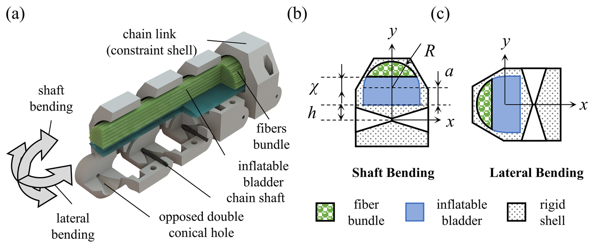
Figure 3Design of the VSOC. (a) Structure of the VSOC. (b) Cross-sectional view under the shaft bending mode. (c) Cross-sectional view under lateral bending mode.
3.1 Structural design and jamming principle
The VSOC consists of a series of sequentially connected, identical chain links. Each link is designed to fulfill two primary functions: facilitating omnidirectional bending in the slipping state in the low-stiffness stage and enabling effective fiber compaction to achieve the jamming state in the high-stiffness stage.
Omnidirectional bending is achieved through a specialized joint mechanism between adjacent links. A shaft is inserted into opposing double-conical holes machined into the mating surfaces of neighboring link bodies. This configuration provides a ball-joint-like connection, enabling multi-axis rotation while preserving structural integrity and load transfer. The conical geometry intrinsically limits the range of motion in directions orthogonal to the primary bending axis.
To house the fiber bundle, each link body is constructed as a rigid shell with a continuous internal cavity. The cavity comprises a semi-cylindrical channel of radius R, integrated with a rectangular section of width 2R and height a, which together provide a rigid constraint along the entire length of the bundle. A key innovation of the design is the integration of a positive-pressure actuation system. A soft airtight inflatable bladder, placed along the flat base of the channel, serves as the actuating element. Upon pressurization, the bladder expands radially, compacting the fiber bundle uniformly against the curved cavity wall. In the present model, the bladder is treated as a compliant pressure-transmission medium, and its bending stiffness as well as membrane-induced non-uniform deformation are neglected in the local pressure distribution. Accordingly, the bladder pressure is taken as the effective jamming pressure p acting on the fiber bundle. This simplification is supported by the present prototype configuration, in which the bladder is only 0.1 mm thick and made of soft polyethylene, serving primarily to transmit pressure and compact the fibers. The resulting contact pressure p acts as the confining hydrostatic pressure essential for fiber jamming, as described in Sect. 2, effectively inducing and maintaining the bundles' jamming state.
3.2 Bending stiffness model for shaft and lateral modes
The unique double-conical joint design leads to two distinct bending modes for the VSOC, as depicted in Fig. 3, each characterized by distinct kinematic constraints and neutral axis orientations.
The shaft bending is defined as rotation purely about the axis of the connecting shafts, as shown in Fig. 3b. The section rotates around the x axis in Fig. 3b. This mode represents the chains' dominant least-constrained deformation path. The lateral bending is defined as rotation about an axis orthogonal to the shaft axis, as shown in Fig. 3c. The section rotates around the x axis in Fig. 3c. This motion is constrained by the interaction between the shaft and the walls of the double-conical holes, resulting in a substantially smaller allowable range of motion compared to the shaft bending mode.
The pressurized compaction of the fiber bundle critically alters its effective cross-sectional geometry for mechanical analysis, as shown in Fig. 3b. In the unpressurized state, the fibers loosely fill the entire semi-circular area. Under pressure, the expanding bladder compacts the fibers upward, creating a densely packed region. The compaction is characterized by a height χ, measured from the cavity base to the lower boundary of the compacted fiber mass. Consequently, the effective cross-sectional domain D for calculating the jammed-state moment of inertia Eq. (4) is not the full semi-circle but a truncated circular segment. Accounting for this compaction effect is essential for accurate stiffness modeling.
The equivalent moments of inertia in the jamming state differ for the two bending modes because their neutral axes are oriented differently relative to the compacted fiber cross-section. For shaft bending, the neutral axis is parallel to the shaft axis and located at distance h from the bottom of the semi-circle. The moment of inertia is derived by integrating the second moment of area about this neutral axis over the compacted region D (y from χ to R):
Here, y+h is the distance from the area element to the shaft bending neutral axis, and the term is the horizontal width of the cross-section at height y. Evaluating this integral yields
For lateral bending, the neutral axis is orthogonal to the shaft axis and lies along the centroidal axis of the compacted cross-section. The corresponding moment of inertia is calculated by integrating about this axis:
where the term represents the vertical height of the compacted fiber area at a given lateral position y for χ≤y.
3.3 Critical shear force for state transition
The geometric difference between the bending modes also influences the critical shear force QJ for the transition from the jamming state, as defined in Eq. (2). The calculation of QJ requires knowledge of the maximum shear stress τmax(Q) for the specific cross-sectional shape under a shear force Q. To obtain tractable analytical expressions, we approximate the shear stress distribution with that of a rectangular section of comparable dimensions, a common simplification in mechanics for complex geometries.
For lateral bending, the compacted cross-section is approximately symmetric. Using the parabolic shear stress formula for a rectangle of area A and height 2R, the distribution of τ can be expressed as
Obviously, the maximum occurs at y = 0, giving . Setting this equal to μp as presented in Eq. (1) and solving for Q gives the critical force for this mode:
For shaft bending, the cross-section is asymmetric about its neutral axis. The approximate shear stress distribution for an equivalent rectangle is modified to
The maximum stress occurs at y=h, yielding . Applying the slip initiation condition leads to the critical shear force for shaft bending:
Conversely, the slipping state shear force limit QS (Eq. 3) and the slipping state moment of inertia IS (Eq. 8) are independent of the bending mode. QS=μpA depends solely on the total fiber cross-sectional area A and the friction-pressure product. IS, derived from energy considerations involving individual fiber bending and aggregate frictional dissipation, depends on the material properties, fiber geometry, and total pressure but not on the specific orientation of the global neutral axis during bending.
To quantitatively characterize the mechanical performance and validate the theoretical model of the proposed variable stiffness chain, a systematic experimental investigation was conducted using a three-point bending test.
4.1 Prototype fabrication and test setup
Test specimens were fabricated according to the design in Sect. 3. Each chain link was assembled by bolting together two 3D-printed resin shells to form a cavity with R = 6 mm, h = 4 mm, and a = 3 mm. This cavity housed a bundle of 700 nylon fibers, each measuring 0.4 mm in diameter. Adjacent links, with a center-to-center distance of 12 mm, were connected via stainless-steel shafts seated in opposing double-conical holes machined into the mating interfaces. The distance from the flat base of the semi-circular cavity to the axis of the connecting shaft was 5 mm. The key parameters of the link structure are shown in Fig. 4a. A polyethylene inflatable bladder (selected because of its flexibility and for being airtight), with a width of 10 mm and a thickness of 0.1 mm, was integrated along the base of the cavity to apply positive jamming pressure to the fiber bundle.
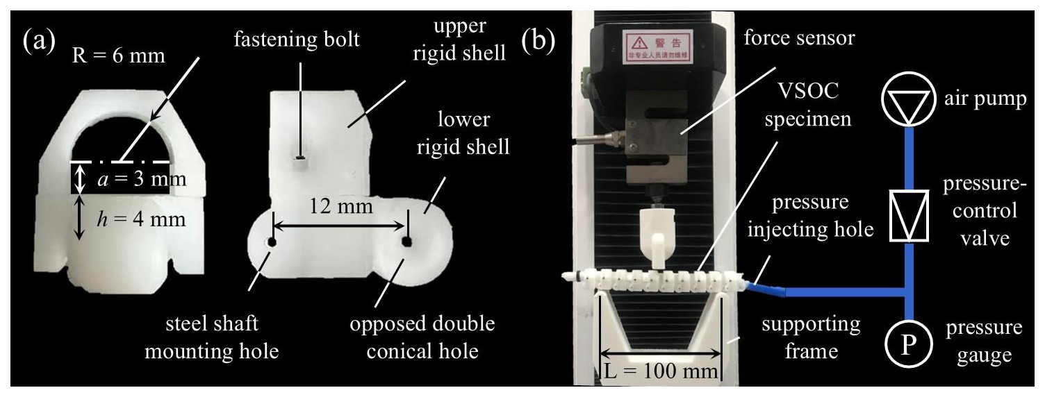
Figure 4Specimen geometry and experimental setup. (a) Key dimensions of a single chain link. (b) Photograph of the three-point bending test configuration and an illustration of the pressure-control system.
The three-point bending setup is illustrated in Fig. 4b. A multi-link chain segment was mounted on a custom support frame with a fixed span length L=100 mm. The support frame was fabricated from 3D-printed ABS (acrylonitrile butadiene styrene). Each support end consisted of a 5 mm diameter cylindrical head. A 1 mm depth groove was formed in the middle of the cylindrical head to suppress off-axis sway during bending while still allowing approximate rotational freedom at the supports. The contact between the specimen and the supports was dry friction, and the overall boundary condition was therefore treated as approximately simply supported for the present stiffness analysis. A universal testing machine equipped with a load cell was used to apply a central deflection using a flat indenter with a contact width of 10 mm at a constant rate of 20 mm min−1, while simultaneously recording the applied force F and the corresponding displacement δ. This loading condition can be seen as quasi-static.
To investigate variable stiffness behavior under different confinement levels, the jamming pressure in the inflatable bladder was systematically controlled, ranging from 0 to 300 kPa in increments of 50 kPa. The bladder pressure was supplied by an independent air pump, measured by a dedicated pressure gauge and regulated by a pressure-control valve. Before each test, the specimen was first placed in a straightening fixture to maintain an initially straight configuration. The bladder was then pressurized to the target value by adjusting the control valve, after which the specimen was transferred to the support frame for deformation measurement. For each pressure level, tests were conducted separately for the two primary bending modes: shaft bending and lateral bending. Each combination of pressure and bending mode was repeated five times to ensure statistical reliability, yielding a complete set of load-deflection (F-δ) curves for analysis.
4.2 Data processing and parameter extraction algorithm
The raw experimental data F-δ for both shaft and lateral bending modes are plotted as gray dots in Fig. 5a and b. To extract statistically representative mechanical responses and to evaluate experimental variability, a systematic data processing procedure was implemented.
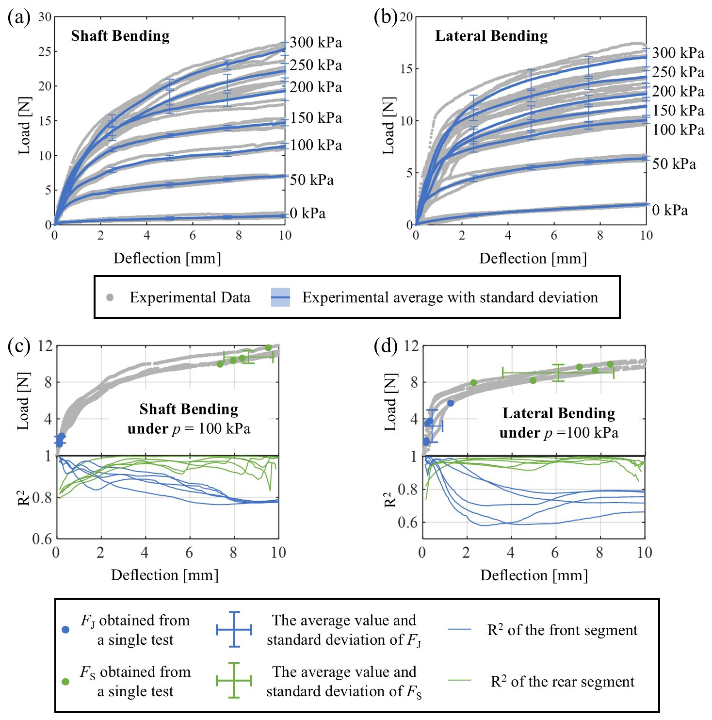
Figure 5Experimental load-deflection responses and parameter extraction. Average curves with ±1 standard deviation bands for (a) shaft bending and (b) lateral bending under various jamming pressures (0–300 kPa). Representative data at 100 kPa illustrating the adaptive piecewise linear regression algorithm used to identify the critical loads FJ (blue) and FS (green) for (c) shaft bending and (d) lateral bending. The curves above show the relationship between deflection and the coefficient of determination (R2) for each linear fit.
To facilitate direct comparison across repeated tests, the raw F-δ curves from the five repetitions for each experimental condition (jamming pressure and bending mode) were spatially aligned onto a unified displacement coordinate system. This was achieved by defining a common displacement grid with 1000 uniformly spaced points spanning from 0 to 10 mm. For each individual raw curve, the corresponding load values were mapped onto this common grid using piecewise linear interpolation, ensuring all datasets shared an identical abscissa. Subsequently, for each unique combination of pressure and bending mode, the average load at each displacement point was calculated from the five aligned curves, yielding a representative average F-δ curve. Concurrently, the standard deviation of the load was computed at each point to quantify data dispersion. A standard deviation band, defined as the average curve ±1 standard deviation, was then constructed to visually display the data dispersion and experimental repeatability.
The analysis of the standard deviation bands reveals a clear trend of increasing data dispersion with higher jamming pressure. The maximum standard deviation for lateral bending increased from 0.0354 N at 0 kPa to 5.4215 N at 300 kPa, while for shaft bending, it rose from 0.0681 to 1.9934 N over the same pressure range. This heightened dispersion under elevated pressure is likely attributable to less-uniform stick-slip-like slipping between fibers, which introduces greater stochasticity into the macroscopic load-deflection response.
To objectively quantify the key mechanical parameters – specifically, the critical loads at stiffness transitions (FJ, FS) and the corresponding stiffness values in the high- and low-stiffness stages (KH, KL) – an adaptive piecewise linear regression algorithm was developed. This data-driven approach was applied to each individual processed F-δ curve to autonomously locate the transition points between distinct linear-response phases, thereby eliminating subjective bias.
The algorithm operates in two sequential stages to identify the linear regimes corresponding to the jamming (high-stiffness) and slipping (low-stiffness) states.
First stage. Jamming state identification: for each deflection point across the entire displacement range, a proportional (zero-intercept) linear fit of the form F=KHδ is performed on all data points up to that deflection. The coefficient of determination R2 is computed for this fit to quantify the linearity of the jamming state response. The deflection that yields the maximum R2 is selected as the optimal boundary between the high-stiffness stage and the subsequent transition stage. The corresponding load is recorded as the first critical load FJ, and the slope of the proportional fit defines the high-stiffness stage stiffness KH.
Second stage. Slipping state identification: the algorithm scans the data to locate the onset of the stable low-stiffness stage. For each deflection point, a standard linear (intercept-included) fit is performed on all data points from that deflection to the end of the displacement range. The R2 value is again computed, and the deflection maximizing R2 after FJ is taken as the optimal start of the slipping state. The load at this location is recorded as the second critical load FS, and the slope of the linear fit to the subsequent data segment defines the slip-state stiffness KL.
This automated procedure was applied uniformly across the entire dataset, except for the 0 kPa condition. Since no jamming pressure is applied under this condition, the fiber bundle remains in a fully slipping state, and its load-deflection response does not exhibit the distinct three-stage characteristics – the jamming, transition, and slipping states – required for the piecewise linear algorithm. Therefore, the dataset subjected to parameter extraction comprised 60 individual curves (6 pressure levels × 2 bending modes × 5 repeats). For each tested condition, the extracted parameters from all five repeats were aggregated, and their mean values along with standard deviations were calculated. This provides a statistically reliable foundation for analyzing the relationship between mechanical behavior and jamming pressure.
Figure 5c and d exemplify the parameter identification process for shaft bending and lateral bending, respectively, under a jamming pressure of 100 kPa. Each subfigure presents the five individual F-δ curves. The overlaid blue and green lines trace the R2 values for the high-stiffness and low-stiffness linear fits, respectively, as the algorithm scans the displacement axis. The algorithmically determined FJ and FS values for each repeat are marked by blue and green dots on the corresponding curves. The mean and standard deviation of these identified critical loads are annotated on the plots, illustrating the consistency and outcome of the extraction method.
5.1 Identification of material parameters
In the present study, the fiber modulus E was not obtained from an independent material test. Instead, an effective modulus suitable for the structure-level model was identified from the bending response under zero jamming pressure (p = 0 kPa), where inter-fiber friction is absent. At p = 0, the inter-fiber friction contribution in Eq. (7) vanishes, and the slipping state equivalent moment of inertia reduces to IS=NIfib. For a three-point bending test, the stiffness KL is related to the equivalent bending rigidity by . The value of KL at p = 0 kPa was obtained via linear regression (R2=0.785) of the corresponding load-deflection data. Combining this with the known structural geometry yielded an effective fiber modulus E = 4.85 GPa, with a 95 % confidence interval of [4.765, 4.925] GPa.
The model response is sensitive to this parameter. According to Eq. (10), the friction-related contribution to IS scales with ; thus, a larger E reduces the friction-derived component of the slipping state equivalent moment of inertia predicted by the model. In addition, because IJ is back-calculated from the measured jamming state stiffness through , a larger assumed E leads to a proportionally smaller identified IJ for the same experimental stiffness KH. Consequently, variations in E affect both the identified equivalent moments of inertia and the agreement between theoretical predictions and experimentally inferred parameters.
The established theoretical model, specifically Eq. (3), QS=μpA, provides the direct way to identify the effective static friction coefficient μ between fibers, where the total cross-sectional area is , with N = 700 (number of fibers) and d = 0.4 mm (fiber diameter). Linear regression was performed on the experimentally identified full-slipping load FS versus jamming pressure p data for both shaft and lateral bending modes. In the three-point bending configuration, the shear force Q is related to the applied load F by . Consequently, the slope from the regression relates to the friction coefficient via .
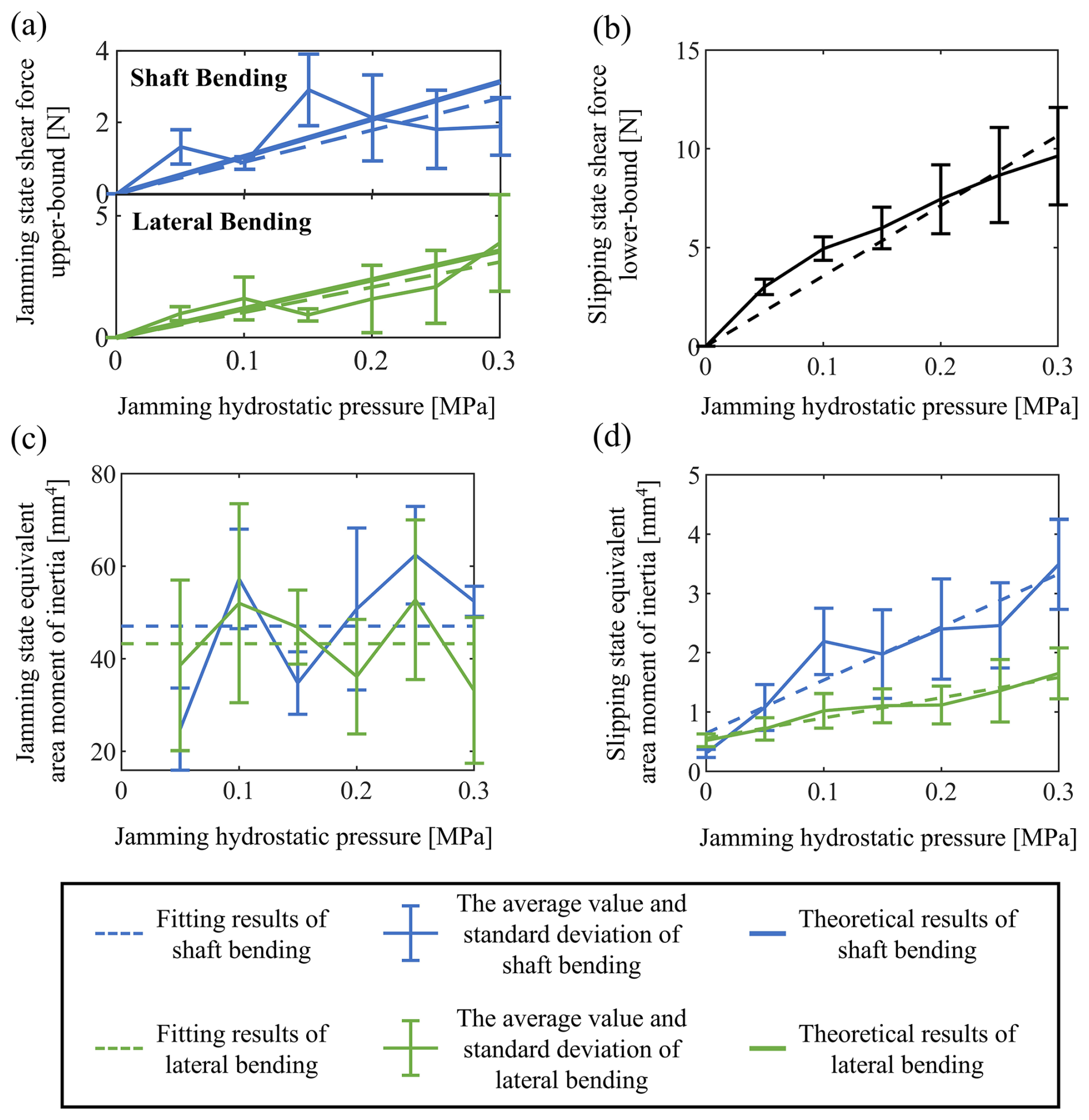
Figure 6Correlation between experimental mechanical parameters and jamming pressure. (a) Critical shear force for jamming-to-slipping transition (QJ) versus jamming pressure for both bending modes. (b) Critical shear force for slipping (QS) versus jamming pressure. (c) Equivalent moment of inertia in the jammed state (IJ). (d) Equivalent moment of inertia in the slip state (IS).
The regression for the combined dataset, shown in Fig. 6b, demonstrates a strong linear correlation with a high coefficient of determination (R2 = 0.817). This statistically significant relationship robustly validates the fundamental assumption of a pressure-dependent Coulomb friction interface. The identified effective inter-fiber static friction coefficient is μ = 0.3665, with a 95 % confidence interval of [0.3433, 0.3897]. The narrow confidence interval indicates a precise estimate, and the value itself falls within a plausible range for interfacing polymer surfaces under confinement, lending credibility to the model.
5.2 Validation of critical load models
The theoretical model predicts a direct proportionality between the jamming pressure p and the two critical shear forces: QJ for the onset of slip and QS for full slipping. The validity of these relationships was tested against the experimental data using the material constants identified in Sect. 5.1.
For shaft bending, the relationship between and p is shown in Fig. 6a. Linear regression yields R2 = 0.4311. The 95 % confidence interval for the proportionality coefficient is [6.8795, 10.9578] N kPa−1. This interval perfectly encompasses the theoretical value of 9.9763 N kPa−1, calculated using the identified μ and the geometric factor ksh from Eq. (2). The relative error between the fitted coefficient (9.0591 N kPa−1) and the theoretical value is 8.5 %. Taken together, these results suggest reasonable agreement with theory, but they also indicate that jamming pressure is a dominant factor rather than the sole determinant of the measured critical load.
Similarly, for lateral bending, the vs. p data (Fig. 6a) also support a proportional trend, with a linear fit yielding R2 = 0.4475. The 95 % confidence interval for the fitted coefficient is [8.1129, 12.5543] N kPa−1, which again fully contains the theoretical prediction of 11.3065 N kPa−1. The relative error between the fitted value (10.4563 N kPa−1) and the theoretical value is 7.6 %. The consistency between the experimental confidence intervals and the theoretical predictions for both bending modes confirms the validity of Eq. (2) in describing the jammed-state load capacity.
The relationship for the slipping state QS∝p is inherently validated by the high-quality linear fit used to identify the friction coefficient μ in Sect. 5.1 and Fig. 6b. Since the expression for QS in Eq. (3) is identical for both bending modes, the data from both were pooled for this analysis, resulting in the strong correlation already discussed. By contrast, the more moderate R2 values for the QJ–p regressions suggest that, although the experimental trend is consistent with the theoretical prediction and the theoretical values fall within the fitted confidence intervals, other sources of variability are also influencing the onset of slip. Plausible contributors include stochastic stick-slip behavior between fibers, non-uniform jamming pressure transmission, and local compaction caused by the bladder and the packing state of the bundle. The influence of these factors requires the construction of more refined theories and more detailed experiments for characterization and description.
5.3 Pressure dependence of bending stiffness
The equivalent area moment of inertia in the jamming state IJ was calculated from the measured stiffness KH using the relation and the identified effective fiber modulus E used in the present structure-level model. As theorized in Sect. 3.2 and shown in Fig. 6c, IJ remains largely independent of jamming pressure p. For shaft bending, the mean IJ is 47.02 mm4 (95 % CI: [40.89, 53.14]), and for lateral bending, it is 43.22 mm4 (95 % CI: [37.00, 49.43]). This pressure independence confirms that, once jammed, the fiber bundle acts as a monolithic beam whose bending stiffness is primarily governed by its compacted geometric shape and the effective fiber modulus used in the present structure-level model, rather than by the pressure level itself. The mean compaction heights χ inferred from these IJ values are 5.51 mm for shaft bending and 3.20 mm for lateral bending, consistent with the compaction shown in Fig. 4.
Conversely, the equivalent moment of inertia in the slipping state IS, derived from the measured stiffness KL, shows a clear linear increase with jamming pressure p (Fig. 6d), as predicted by Eq. (8). For shaft bending, the fitted slope is 8.95 mm4 kPa−1 (R2 = 0.651), and for lateral bending, it is 3.41 mm4 kPa−1 (R2 = 0.551).
Although only one specimen configuration was tested experimentally, the analytical form of the model makes its parameter dependence explicit. According to Eq. (2), QJ is proportional to the friction coefficient μ, the jamming pressure p, and the geometry-dependent coefficient k, so variations in frictional conditions or section geometry will directly affect the onset of slip. According to Eq. (3), QS is proportional to μpA. Since the total cross-sectional area A depends directly on the number of fibers N and the fiber diameter d, both parameters are expected to directly influence the full-slipping threshold. Likewise, Eq. (10) shows that IS depends on E, N, and Ifib, indicating that both material properties and bundle geometry will modify the slope of the low-stiffness stage. Therefore, the model structure allows extension to parameter variations, but the robustness of these dependencies has not been validated here through inter-specimen experiments using different fiber types, diameters, or fiber counts.
This study presented the design, modeling, and prototype-level experimental assessment of a VSOC based on a positive-pressure fiber jamming mechanism. Compared with conventional vacuum-based fiber jamming structures, the main contribution of this work is not merely the use of a different pressure source but the establishment of a dedicated positive-pressure FJS architecture, together with a bending model that links pressure, state transitions, and stiffness evolution in a unified framework.
The model distinguishes the jamming, transition, and slipping states; derives the critical shear forces governing the state transitions; and formulates a pressure-dependent equivalent area moment of inertia for the two primary bending modes of the VSOC. Three-point bending experiments on the present prototype were then used to examine this framework over the tested pressure range. The experimental trends were broadly consistent with the model predictions: both critical forces (QJ, QS) and the slipping state stiffness (IS) increased approximately linearly with jamming pressure, whereas the jamming state stiffness (IJ) remained comparatively insensitive to pressure and was governed mainly by the compacted geometry. These results support the interpretability of the proposed structure model framework for the present prototype and tested conditions.
The present conclusions should also be read together with the model limitations. The quadratic relation between slipped area ratio and Q is introduced as a phenomenological approximation for the transition regime rather than as a rigorously established law. The experimental validation is restricted to a single VSOC prototype with a single fiber type, fiber diameter, and fiber count, so the model's generality has not been tested through cross-specimen experiments. In addition, the parameter E is currently the system-level identified effective fiber modulus obtained from the p = 0 kPa bending response, rather than an independently measured fiber modulus, and should therefore be cross-validated in future work by direct material testing.
Regarding potential applications and current constraints, the proposed VSOC may be useful as a variable stiffness joint in soft manipulators or continuum robots, where compliant motion during interaction and increased stiffness during load bearing are both desirable. It may also be relevant to reconfigurable gripping and positioning structures that benefit from omnidirectional articulation together with pressure-tunable rigidity. At the same time, the current prototype still has practical constraints, most notably the need for an external positive-pressure source, which may limit portability and system integration in some application scenarios. Future work will focus on optimizing the dynamic response, refining the friction model for varying slip velocities, and exploring integrated sensing for closed-loop stiffness control.
No data sets were used in this article.
JY conceived and supervised the study. SZ performed the formal analysis, conducted the experimental investigation, and wrote the paper draft. JY reviewed and edited the paper.
The contact author has declared that neither of the authors has any competing interests.
Publisher's note: Copernicus Publications remains neutral with regard to jurisdictional claims made in the text, published maps, institutional affiliations, or any other geographical representation in this paper. The authors bear the ultimate responsibility for providing appropriate place names. Views expressed in the text are those of the authors and do not necessarily reflect the views of the publisher.
The authors thank the reviewers for their critical and constructive review of the paper.
This research has been supported by the National Natural Science Foundation of China (grant no. 52375030) and the Hebei Natural Science Foundation (grant no. E2025203232).
This paper was edited by Pengyuan Zhao and reviewed by two anonymous referees.
Aktaş, B., Narang, Y. S., Vasios, N., Bertoldi, K., and Howe, R. D.: A Modeling Framework for Jamming Structures, Adv. Funct. Mater., 31, 2007554, https://doi.org/10.1002/adfm.202007554, 2021.
Arleo, L. and Cianchetti, M.: VARISA – A VARIable Stiffness soft robotics Arm based on inverse pneumatic actuators and differential drive fiber jamming, Mechatronics, 102, 103230, https://doi.org/10.1016/j.mechatronics.2024.103230, 2024.
Arleo, L., Pozzi, J., Pagliarani, N., and Cianchetti, M.: Sea Shell Bioinspired Variable Stiffness Mechanism Enabled by Hybrid Jamming Transition, in: 2023 IEEE International Conference on Soft Robotics (RoboSoft), 2023 IEEE International Conference on Soft Robotics (RoboSoft), 1–7, https://doi.org/10.1109/RoboSoft55895.2023.10121930, 2023.
Bai, L., Yan, H., Li, J., Shan, J., and Hou, P.: Detachable Soft Actuators with Tunable Stiffness Based on Wire Jamming, Appl. Sci., 12, 3582, https://doi.org/10.3390/app12073582, 2022.
Brancadoro, M., Manti, M., Tognarelli, S., and Cianchetti, M.: Preliminary experimental study on variable stiffness structures based on fiber jamming for soft robots, in: IEEE International Conference on Soft Robotics (RoboSoft), Livorno, Italy, 258–263, https://doi.org/10.1109/ROBOSOFT.2018.8404929, 2018.
Brancadoro, M., Manti, M., Tognarelli, S., and Cianchetti, M.: Fiber Jamming Transition as a Stiffening Mechanism for Soft Robotics, Soft Robot., 7, 663–74, https://doi.org/10.1089/soro.2019.0034, 2020.
Brown, E., Rodenberg, N., Amend, J., Mozeika, A., Steltz, E., Zakin, M. R., Lipson, H., and Jaeger, H. M.: Universal robotic gripper based on the jamming of granular material, P. Natl. Acad. Sci. USA, 107, 18809–18814, https://doi.org/10.1073/pnas.1003250107, 2010.
Caruso, F., Mantriota, G., Afferrante, L., and Reina, G.: A theoretical model for multi-layer jamming systems, Mech. Mach. Theory, 172, 104788, https://doi.org/10.1016/j.mechmachtheory.2022.104788, 2022.
Caruso, F., Mantriota, G., Moramarco, V., and Reina, G.: Layer jamming: Modeling and experimental validation, Int. J. Mech. Sci., 251, 108325, https://doi.org/10.1016/j.ijmecsci.2023.108325, 2023.
Crowley, G. B., Zeng, X., and Su, H.-J.: A 3D Printed Soft Robotic Gripper With a Variable Stiffness Enabled by a Novel Positive Pressure Layer Jamming Technology, IEEE Robot. Autom. Lett., 7, 5477–5482, https://doi.org/10.1109/LRA.2022.3157448, 2022.
Do, B. H., Wu, S., Zhao, R. R., and Okamura, A. M.: Stiffness Change for Reconfiguration of Inflated Beam Robots, Soft Robot., 11, 779–790, https://doi.org/10.1089/soro.2023.0120, 2024.
Fitzgerald, S. G., Delaney, G. P., and Howard, D.: A Review of Jamming Actuation in Soft Robotics, Actuators, 9, https://doi.org/10.3390/act9040104, 2020.
He, L., Herzig, N., de Lusignan, S., and Nanayakkara, T.: Granular Jamming Based Controllable Organ Design for Abdominal Palpation, in: 2018 40th Annual International Conference of the IEEE Engineering in Medicine and Biology Society (EMBC), 2154–2157, https://doi.org/10.1109/EMBC.2018.8512709, 2018.
Henke, M. and Gerlach, G.: On a high-potential variable-stiffness device, Microsyst. Technol., 20, 599–606, https://doi.org/10.1007/s00542-013-1995-5, 2014.
Ibrahimi, M., Paternò, L., Ricotti, L., and Menciassi, A.: A Layer Jamming Actuator for Tunable Stiffness and Shape-Changing Devices, Soft Robot., 8, 85–96, https://doi.org/10.1089/soro.2019.0182, 2021.
Jadhav, S., Majit, M. R. A., Shih, B., Schulze, J. P., and Tolley, M. T.: Variable Stiffness Devices Using Fiber Jamming for Application in Soft Robotics and Wearable Haptics, Soft Robot., 9, 173–186, https://doi.org/10.1089/soro.2019.0203, 2022.
Kawamura, S., Yamamoto, T., Ishida, D., Ogata, T., Nakayama, Y., Tabata, O., and Sugiyama, S.: Development of passive elements with variable mechanical impedance for wearable robots, in: Proceedings of IEEE International Conference on Robotics and Automation, IEEE International Conference on Robotics and Automation, Washington, DC, USA, 248–253, https://doi.org/10.1109/ROBOT.2002.1013369, 2002.
Kawamura, S., Kanaoka, K., Nakayama, Y., Jinwoo Jeon, and Fujimoto, D.: Improvement of passive elements for wearable haptic displays, in: 2003 IEEE International Conference on Robotics and Automation (Cat. No.03CH37422), IEEE ICRA 2003, Taipei, Taiwan, 816–821, https://doi.org/10.1109/ROBOT.2003.1241694, 2003.
Laschi, C., Mazzolai, B., and Cianchetti, M.: Soft robotics: Technologies and systems pushing the boundaries of robot abilities, Science Robotics, 1, https://doi.org/10.1126/scirobotics.aah3690, 2016.
Liu, A. J. and Nagel, S. R.: Jamming is not just cool any more, Nature, 396, 21–22, https://doi.org/10.1038/23819, 1998.
Liu, T., Xia, H., Lee, D.-Y., Firouzeh, A., Park, Y.-L., and Cho, K.-J.: A Positive Pressure Jamming Based Variable Stiffness Structure and its Application on Wearable Robots, IEEE Robot. Autom. Lett., 6, 8078–8085, https://doi.org/10.1109/LRA.2021.3097255, 2021.
Manti, M., Cacucciolo, V., and Cianchetti, M.: Stiffening in Soft Robotics: A Review of the State of the Art, IEEE Robot. Automat. Mag., 23, 93–106, https://doi.org/10.1109/MRA.2016.2582718, 2016.
Narang, Y. S.: Achieving mechanical versatility in robots and structures through laminar jamming, PhD Thesis, Harvard University, https://dash.harvard.edu/entities/publication/3cb7edfa-f58f-4f1a-9ab0-fde621ccab57 (last access: 5 May 2026), 2018.
Narang, Y. S., Vlassak, J. J., and Howe, R. D.: Mechanically Versatile Soft Machines through Laminar Jamming, Adv. Funct. Mater., 28, 1707136, https://doi.org/10.1002/adfm.201707136, 2018a.
Narang, Y. S., Degirmenci, A., Vlassak, J. J., and Howe, R. D.: Transforming the Dynamic Response of Robotic Structures and Systems Through Laminar Jamming, IEEE Robot. Autom. Lett., 3, 688–695, https://doi.org/10.1109/LRA.2017.2779802, 2018b.
Narang, Y. S., Aktaş, B., Ornellas, S., Vlassak, J. J., and Howe, R. D.: Lightweight Highly Tunable Jamming-Based Composites, Soft Robot., 7, 724–735, https://doi.org/10.1089/soro.2019.0053, 2020.
Pinskier, J., Brett, J., Hanson, L., Surdo, K. L., and Howard, D.: Jammkle: Fibre jamming 3D printed multi-material tendons and their application in a robotic ankle, in: 2022 IEEE/RSJ International Conference on Intelligent Robots and Systems (IROS), 8507–8514, https://doi.org/10.1109/IROS47612.2022.9982171, 2022.
Steltz, E., Mozeika, A., Rodenberg, N., Brown, E., and Jaeger, H. M.: JSEL: Jamming Skin Enabled Locomotion, in: 2009 IEEE/RSJ International Conference on Intelligent Robots and Systems (IROS 2009), St. Louis, MO, USA, 5672–5677, https://doi.org/10.1109/IROS.2009.5354790, 2009.
Sun, J., Lin, B., Ramirez, L. A., Figueroa, E., Baines, R., Yang, B., Marroquin, E., and Kramer-Bottiglio, R.: Performance Enhancement of a Morphing Limb for an Amphibious Robotic Turtle, in: 2024 IEEE 7th International Conference on Soft Robotics (RoboSoft), 374–379, https://doi.org/10.1109/RoboSoft60065.2024.10521924, 2024.
Tabata, O., Konishi, S., Cusin, P., Ito, Y., Kawai, F., Hirai, S., and Kawamura, S.: Microfabricated tunable bending stiffness device, in: Proceedings IEEE Thirteenth Annual International Conference on Micro Electro Mechanical Systems (Cat. No.00CH36308), Miyazaki, Japan, 23–27, https://doi.org/10.1109/MEMSYS.2000.838484, 2000.
Vasios, N., Narang, Y., Aktaş, B., Howe, R., and Bertoldi, K.: Numerical analysis of periodic laminar and fibrous media undergoing a jamming transition, Eur. J. Mech. A-Solid., 75, 322–329, https://doi.org/10.1016/j.euromechsol.2019.02.002, 2019.
Wang, L., Yang, Y., Chen, Y., Majidi, C., Iida, F., Askounis, E., and Pei, Q.: Controllable and reversible tuning of material rigidity for robot applications, Mater. Today, 21, 563–576, https://doi.org/10.1016/j.mattod.2017.10.010, 2018.
Wu, C., Zhao, P., Chen, P., Ni, Z., Yue, S., Li, L., Zhang, D., and Hao, G.: Design, dynamic modelling and experimental study on a tether-net system for active debris removal, Mech. Mach. Theory, 208, 105958, https://doi.org/10.1016/j.mechmachtheory.2025.105958, 2025.
Yang, B., Baines, R., Shah, D., Patiballa, S., Thomas, E., Venkadesan, M., and Kramer-Bottiglio, R.: Reprogrammable soft actuation and shape-shifting via tensile jamming, Sci. Adv., 7, eabh2073, https://doi.org/10.1126/sciadv.abh2073, 2021.
Yu, H., Lv, M., Hu, B., Zhang, Y., and Zhao, P.: Review article: A review of control technologies for soft robots: from structural design to intelligent control, Mech. Sci., 17, 313–332, https://doi.org/10.5194/ms-17-313-2026, 2026.