the Creative Commons Attribution 4.0 License.
the Creative Commons Attribution 4.0 License.
 | 16 Apr 2026
A multi-segment serial–parallel spatial closed-chain capture mechanism based on bionic principles
Xingqi Yin
Xuemin Sun
Zhihong Chen
Xianhong Zhang
Ruiming Li
Yanan Yao
With the rapid increase in the number of spacecraft, the number of various non-cooperative targets and failed spacecraft has risen sharply. Consequently, dealing with these targets requires the actuator to possess high flexibility, high enveloping ability, and structural stability. Following bionic principles, this paper proposes a multi-segment serial–parallel spatial closed-chain capture mechanism. The mechanism is formed by coupling a single parallel capture mechanism composed of four-URU four-branch parallel mechanism and double-loop folding expansion platform. First, the configuration design of the single parallel capture mechanism with the core structure of the double-loop folding expansion platform plus the four-URU four-branch parallel mechanism is carried out. Secondly, the motion screw system and screw-constraint topological diagram of the mechanism at the initial position are obtained through the null-space method, and then the DOF of the mechanism is calculated. Subsequently, a kinematic analysis of the capture mechanism is performed. Finally, simulations and a prototype model are developed to verify the motion feasibility of the multi-segment serial–parallel spatial closed-chain capture mechanism.
- Article
(7484 KB) - Full-text XML
- BibTeX
- EndNote


Spatial non-cooperative targets refer to spacecraft or debris that lack communication response equipment, obvious identifiers, cooperative beacons, and dedicated docking interfaces and that cannot actively transmit attitude information. Existing capture mechanisms have many problems in handling such non-cooperative targets (Fallahiarezoodar and Zhu, 2025). Currently, the international capture methods for such non-cooperative targets can be divided into two categories: non-contact and contact. Non-contact capture includes methods of driving the target to move by using external forces such as ion jets and laser radiation; its principle is to utilize external forces to cause its orbital decay. The advantages of non-contact capture lie in avoiding collision risks and preventing secondary pollution, while it has drawbacks such as low efficiency and an insufficient adaptability to target shapes (Bigdeli et al., 2025).
Contact capture is further divided into flexible connection capture and rigid connection capture. Flexible connection capture includes flying-claw capture and rope net capture. For example, tethered robots (Meng et al., 2019) use tethers to expand the operation range, and the flying claws can fly out collaboratively to surround the target. Rope net capture envelops and tightens the target through a net cover, such as the Remove DEBRIS project (Forshaw et al., 2016), McGill University's net cover device (Sharf et al., 2017). Rigid connection capture includes single-manipulator capture, which uses an end effector to directly grasp specific parts of the target, such as in the SMART-OLEV project (Kaiser et al., 2008) and Europe's ERA project (Flores-Abad et al., 2014). Multi-manipulator capture achieves enveloping grasping by increasing contact points through multiple-arm collaboration, such as the US RSGS/RSV (Tsiotras et al., 2023), Canada's SSRMS/SPDM small dual-arm robot (Ma et al., 2023).
Spatial closed-chain mechanisms possess both precise manipulation and stable grasping capabilities, such as the Hybrid Space Robot System (HSRS) proposed by An et al. (2025) and the folding expansion gripper based on spatial closed-chain rod mechanisms reported by Xu et al. (2023). Building on this foundation, a series of hybrid serial–parallel closed-chain capture mechanisms have emerged in recent years, which achieve closed enclosures around the target through deployable or foldable structures. Representative designs include the rotary-actuated folding polyhedron (RAD) proposed by Teoh et al. (2018), the deployable polyhedral gripper developed by Xia et al. (2020) and Tang et al. (2024), and the folding deployable mechanism by Gao et al. (2023), all of which employ deployable polyhedral structures to realize enveloping capture. In addition, bio-inspired and underactuated techniques have been introduced into capture mechanism design. The biomimetic octopus underactuated hand proposed by Jia et al. (2017) adapts to targets through a compliant multi-tentacle configuration. The three-limb deployable mechanism (Wang et al., 2022), the truss-shaped deployable grasping mechanism (Gao et al., 2019), and the deployable grasping manipulator (Li et al., 2019) achieve decoupling and compatibility between deployment and grasping via mobility bifurcation or hybrid serial–parallel architectures. Furthermore, the snake-inspired swallowing robot (Zhang et al., 2022) enables synchronous radial and axial deployment, achieving continuous target capture and storage in a swallowing-like manner.
Therefore, summarizing the advantages and disadvantages of the aforementioned mechanisms, this paper proposes a multi-segment serial–parallel spatial closed-chain capture mechanism. Its core innovation lies in the unique configuration that couples a four-URU four-branch parallel mechanism with a double-loop folding expansion platform, endowing the mechanism with high flexibility, strong enveloping capability, and structural stability, enabling it to meet the requirements of non-cooperative targets. Furthermore, the bionic configuration formed by series connection enables more flexible spatial capture and manipulation. The structure of this study is as follows: first, we conduct the mechanism's configuration design and calculate its DOF; thereafter, we establish the kinematic model, perform forward and inverse kinematic analyses and singularity analysis, and verify the workspace; subsequently, we simulate the mechanism and fabricate a prototype model to verify the capture mechanism's motion feasibility; finally, we summarize the study, discuss future research and application scenarios.
Snakes can compress their bodies to a great extent during hunting, stretch after discovering non-cooperative targets, and capture non-cooperative targets with their teeth. which meets the needs of space saving, large-range capture, and target capture. The corresponding relationship between the snake's spine and the multi-segment serial–parallel spatial closed-chain capture mechanism is shown in Fig. 1, and the exploded view of the connecting components of each section is also shown in Fig. 1. This design method can ensure the normal operation of the rotating pair of the double-loop folding expansion platform while ensuring the stability of the fixed platform of the next segment. The muscles are designed using a four-URU four-branch parallel mechanism scheme that combines stability and a high DOF. The spine is designed using a double-loop folding expansion platform scheme that combines a single DOF and a large deployment ratio.
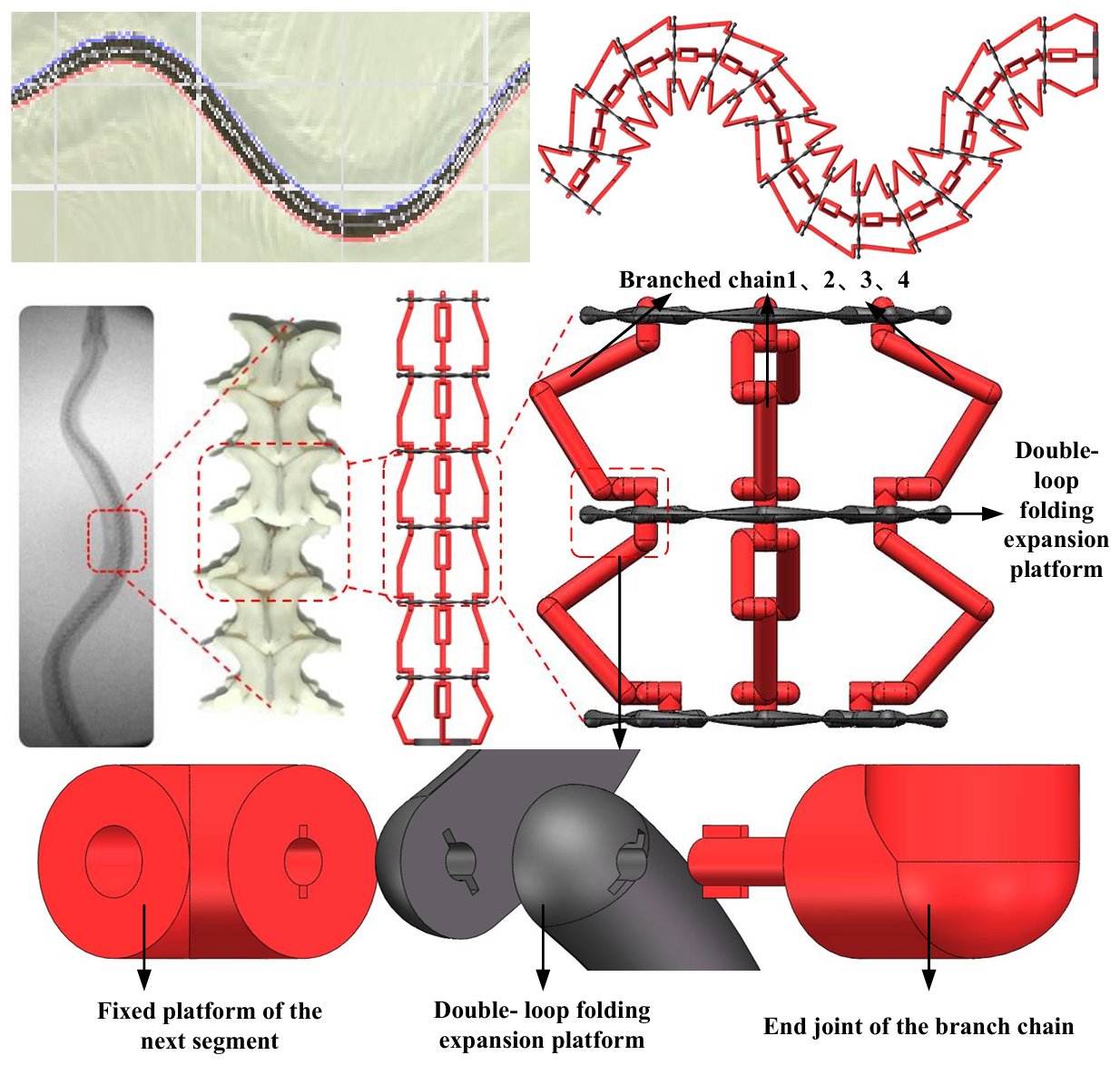
Figure 1Multi-segment serial–parallel spatial closed-chain capture mechanism based on bionic principles and exploded-view diagram of the connection part.
The design of the single parallel capture mechanism adopts the core structure of a double-loop folding expansion platform plus the four-URU four-branch parallel mechanism. The four-URU four-branch mechanism adopts an all-revolute (R) joint configuration for optimal structural layout. Adjacent vertical R joints are integrated into universal (U) joints, equivalent to a four-URU four-branch parallel mechanism. Moreover, the motion axes are rearranged, resulting in the final schematic diagram of the parallel mechanism as shown in Fig. 2a. The double-loop folding expansion platform adopts a Hoberman mechanism with 1 DOF and a large deployment ratio, and Fig. 2b is obtained after rod optimization.
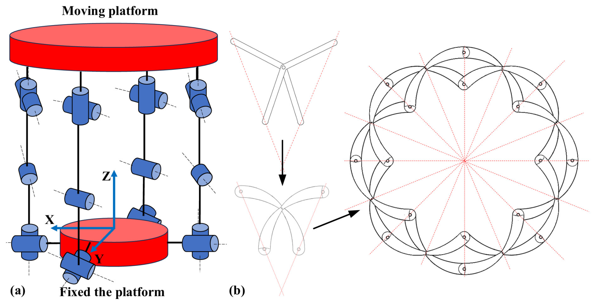
Figure 2Configuration design. (a) Four-URU four-branch parallel mechanism. (b) Double-loop folding expansion platform.
The U joint at the upper end of the four-URU four-branch parallel mechanism is arranged coaxially with the R joint located on the inner loop of the double-loop folding expansion platform to achieve motion coupling. The single parallel capture mechanism forms a multi-segment serial–parallel structure through series connection, as shown in Fig. 3a. This connection mode enables the fixed platform of each segment of the parallel mechanism to share the same coordinate system with the moving platform of the previous segment of the parallel mechanism. Furthermore, each segment of the capture mechanism can be operated independently, as shown in Fig. 3b.
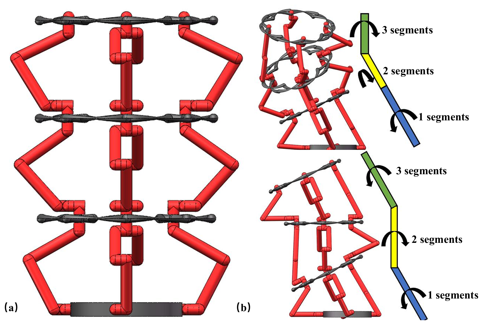
Figure 3Multi-segment serial–parallel spatial closed-chain capture mechanism. (a) Coupling design. (b) Various motion attitudes.
The mechanism is a coupled design of a four-URU four-branch parallel mechanism and a double-loop folding expansion platform, and the null-space method is adopted to conduct the overall DOF analysis of the mechanism (Wei et al., 2010); the single parallel capture mechanism determines the DOF of the multi-segment serial–parallel capture mechanism. A Cartesian coordinate system is established. Four-URU four-branch parallel mechanism and double-loop folding expansion platform coordinate systems are shown in Fig. 4a. Based on the null-space method, the screw constraint topological diagram of the mechanism is constructed as shown in Fig. 4b.
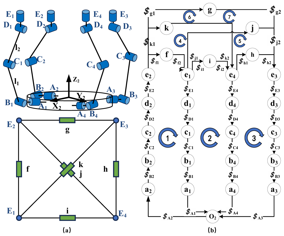
Figure 4(a) Overall coordinate system of the single parallel capture mechanism. (b) Constraint topological diagram of each loop.
The straight lines represent the motion pairs, and the circles represent the connecting links. The dimensions can be expressed as follows: A1B1, A2B2, A3B3, and A4B4 are d1, and BiCi=l1, CiDi=l2, and DiEi=l3 (i=1, 2, 3, 4). The distance between Ai and O2 is R1, and the distance between Ei and O3 is R2, as shown in Fig. 4b. The spatial position coordinates of revolute joint A1 can be obtained as follows:
The axis direction of revolute joint A1 is given by the following:
According to screw theory, the unit motion screw of joint A1 is expressed as follows:
Similarly, the motion screw expressions of each joint can be obtained (Eq. A1 in the Appendix). Let ω represent the angular velocity at each revolute joint. The screw constraint equation of the mechanism can then be written as follows:
The screw constraint equations in matrix form are as follows:
where the constraint matrix N is defined as
and M is given by
In Eq. (7), the expressions of each symbol are shown in Eq. (A2). The screw constraint matrix M is a 7×32 matrix. The DOF of the mechanism corresponds to the dimension of the null space of the constraint matrix. Numerical computation yields the following:
The single parallel capture mechanism has 5 independent DOFs. As the DOF of each module remains independent after series connection, the multi-segment serial–parallel capture mechanism possesses 5n DOFs, where n is the number of segments.
Since the null-space method is a numerical approach, it cannot directly identify the specific type of DOF of the mechanism. Its physical meaning is to determine the number of drives required for the mechanism's movement. Since the double-loop folding platform can change its radial size, by fixing the size of the double-loop folding platform and referring to Liu Yong's paper on the kinematic performance analysis and dimensional optimization of the fully symmetric four-URU parallel mechanism (Liu et al., 2019), it is known that, when the size of the double-loop folding platform is fixed, the remaining 4 DOFs of the moving platform are the translation along the x, y, and z axes and the rotation around the z axis. In practical applications, the translational DOF along the x, y, and z axes can effectively capture non-cooperative targets in various directions. At the same time, the translational DOF along the z axis can also send the captured non-cooperative targets back to the service satellite, which is crucial for the operation of the capture mechanism. The rotational DOF around the z axis enables the capture mechanism to better perform despinning.
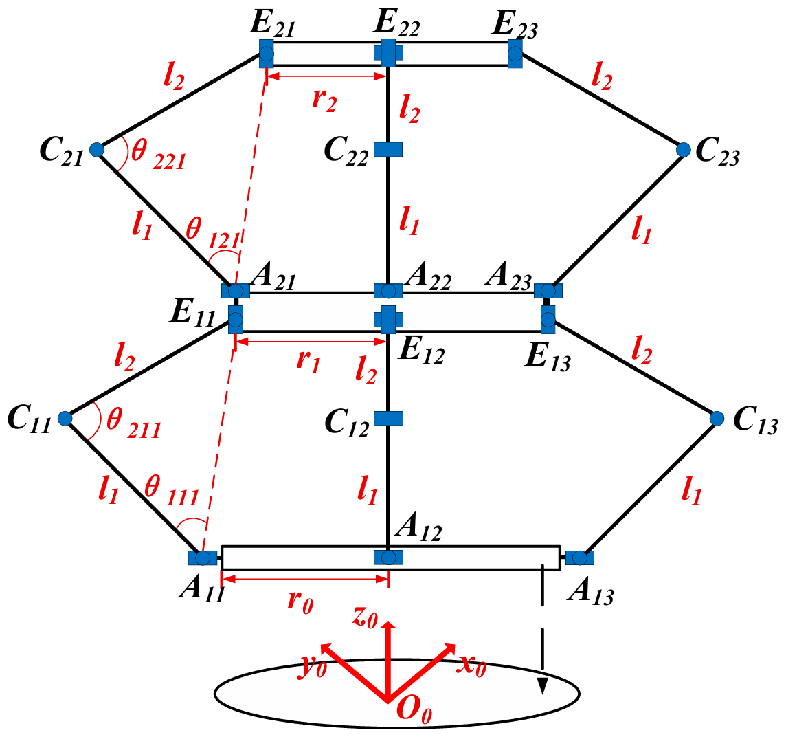
Forward and inverse kinematic analyses are performed on the multi-segment serial–parallel mechanism. To simplify the analysis, the number of segments of the serial–parallel mechanism is set to two, as shown in Fig. 5. The centers of the universal (U) joints connected to the fixed platform are denoted as Ani (n=1, 2) (i=1, 2, 3, 4), and the centers of the U joints connected to the moving platform are Eni. The centers of the revolute (R) joints in the branch chains are Cni. All branch chains of the serial–parallel capture mechanism are in a centrally symmetric distribution. The fixed platform is circular, with a radius of r0; the intermediate moving platform is circular, with a radius of r1; and the end moving platform is circular, with a radius of r2. In the branch chains, the length of the link AniCni is l1, and the length of the link CniEni is l2.
A fixed-coordinate system O0−x0y0z0 is established with the center O0 of the fixed platform as the origin of coordinates. The positive direction of the x axis is parallel to A11A12, the positive direction of the y axis is parallel to A12A13, and the z axis is perpendicular to the fixed platform. A moving-coordinate system O1−x1y1z1 is established with the center O1 of the intermediate moving platform as the origin of coordinates. The positive direction of the x axis is parallel to E11E12, the positive direction of the y axis is parallel to E12E13, and the z axis is perpendicular to the intermediate moving platform. A moving-coordinate system O2−x2y2z2 is established with the center O2 of the end moving platform as the origin of coordinates. The positive direction of the x axis is parallel to E21E22, the positive direction of the y axis is parallel to E22E23, and the z axis is perpendicular to the end moving platform. Among them, the moving platform of the first segment and the fixed platform of the second segment share the same coordinate system, which is uniformly denoted as O1−x1y1z1.
In the initial pose, A11A12 is parallel to E11E12 and E21E22, while A12A13 is parallel to E12E13 and E22E23. The projections of points O1 and O2 on the fixed platform coincide with O0. The links AniCni and CniEni are collinear, and the driving angles are denoted by θ1ni and are θ2ni, as shown in Fig. 5.
The position vectors O0A1i in the fixed-coordinate system O0−x0y0z0, O1E1i in the intermediate moving-platform coordinate system O1−x1y1z1, and O2E2i in the end moving-platform coordinate system O2−x2y2z2 can all be derived based on the respective coordinate systems.
The position vector O0O1 of the origin O1 of the intermediate moving-platform coordinate system in the fixed-coordinate system is , and the position vector O1O2 of the origin O2 of the end moving-platform coordinate system in the intermediate moving-platform coordinate system is .
The pose transformation matrices of the intermediate moving platform relative to the fixed-coordinate system and the end moving platform relative to the intermediate moving-platform coordinate system are as follows:
where “c” denotes cos and “s” denotes sin. The position vectors O1E1i and O2E2i can be converted into the position vectors O0A1i and O1A2i by means of the coordinate transformation method. The coordinate transformation formula obtained by the closed vector method is as follows:
The position vector O0E1i is obtained. Its coordinates in the fixed-coordinate system are as follows:
The position vector O1E2i is obtained. Its coordinates in the intermediate moving-coordinate system are as follows:
The position vectors A1iE1i and A2iE2i can be expressed as follows:
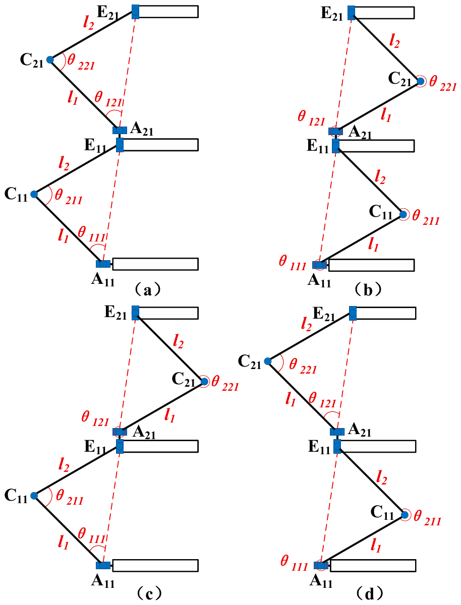
As shown in Fig. 6, in the triangles formed by A1iE1iC1i and A2iE2iC2i, AniCni=l1, CniEni=l2, A1iE1i=d1i, and A2iE2i=d2i. Thus, the inverse-position solution of the mechanism can be obtained by means of the trigonometric theorem.
The branch chain of the first segment is as follows:
The branch chain of the second segment is as follows:
The motions of each branch chain are independent of each other. Each segment of the mechanism has four identical branch chains, and the schematic diagrams of the four poses of the driving rotation angle for each group of branch chains are shown in Fig. 6. Thus, each configuration of the moving platform corresponds to a total of 256 sets of inverse-position solutions for eight branch chains.
The forward-position solution determines the coordinates of the end moving-platform center O2 (xtotal, ytotal, ztotal) in the fixed-coordinate system, as well as the attitude rotation angles α1 and α2 about the z axis given the driving angles θ1ni and θ2ni of each actuated pair.
The driving angles θ1ni and θ2ni are subject to the same trigonometric function constraint. Taking θ1ni as the primary input variable, the equations can be rearranged to obtain the following:
The lengths of A1iE1i (denoted as d1i) and A2iE2i (denoted as d2i) are solved as follows:
When taking and , the kinematic analysis of the mechanism is performed. The solution method for other cases is the same and, according to Eqs. (14) and (18), can obtain the following:
After rearranging Eq. (19), we obtain the following:
The intermediate moving platform rotates by α1 relative to the fixed platform, and the end moving platform rotates by α2 relative to the intermediate moving platform, with both rotations around the z axis. The total attitude angle of the end moving platform is . Using the transformation relation , one obtains the following:
A singular configuration refers to a special posture of the mechanism in which, under given geometric parameters, the constraint relationships degenerate, causing an instantaneous increase in DOF or a loss in actuation capability. In order to investigate the workspace boundary and motion performance of the capture mechanism, the singular configurations of a single four-URU four-branch parallel mechanism are first analyzed. The pose of the moving platform of the first four-URU four-branch parallel mechanism is expressed by the generalized coordinate vector:
Four independent actuated joint variables are selected to form the joint generalized coordinate vector:
The vector is obtained in the fixed-coordinate frame, where is a function of the moving-platform pose x1. Combined with the geometric relationships, the link lengths satisfy the corresponding length constraints. Each branch chain can then be written in the unified form:
Collecting the four branch chain constraints into vector form yields the following:
Differentiating the position constraint Eq. (26) with respect to time gives the velocity constraint of the single four-URU four-branch parallel mechanism:
Let
and then Eq. (27) can be rewritten as
For a regular configuration within the workspace, A1 is a nonsingular matrix; i.e., det(A1)≠0. The instantaneous velocity of the moving platform can be solved as follows:
According to the singularity theory of parallel mechanisms, when the rank of the Jacobian matrix J1 is lower than the number of DOFs, the mechanism is in a singular configuration. From Eq. (30) it follows that, if
the mechanism loses its constraint capability in certain translational or rotational directions; if
an ineffective actuation combination exists.
Let ϕ denote the folding angle, and let ρ denote the equivalent radius of the platform. According to the geometric relationships, one has
where f() is uniquely determined by the geometric constraints of the inner and outer scissor link sets of the double-loop folding expansion platform. The velocity relationship of the double-loop folding expansion platform is as follows:
where JH(ϕ) is the scalar Jacobian of the double-loop folding expansion platform. When JH(ϕ)=0, a folding input cannot generate an effective radial output velocity , and the mechanism is in a singular configuration.
Let the generalized coordinates of the moving platform of the kth four-URU four-branch parallel mechanism be xk, let the actuated joint variables be qk, and let the corresponding velocity Jacobian be
The singularity criterion for Jn is consistent with the single-segment analysis: if det(An)=0, the parallel part of the nth segment is in a parallel singularity; if det(Bn)=0, it is in an actuation singularity.
Meanwhile, the double-loop folding expansion platform of the nth segment satisfies the following:
When , the double-loop folding expansion platform of the nth segment is in a singular configuration.
Although the singular configurations of the proposed serial–parallel spatial closed-chain capture mechanism are theoretically identified through Jacobian-based analysis, their practical implications for on-orbit capture tasks require further discussion. To mitigate these risks in practical applications, several singularity avoidance strategies can be adopted.
At the structural design level, by introducing slight differentiation in the design of the four-URU branches, including adjusting the allowable rotation ranges of the revolute joints and modifying the initial installation angles of the hinges, the strict geometric symmetry of the mechanism can be intentionally broken. As a result, the singular configurations of individual branches no longer occur simultaneously, thereby avoiding the emergence of global singularities. Meanwhile, by keeping the introduced structural variations within reasonable limits, the mechanism preserves its overall near-symmetric characteristics, ensuring that the kinematic performance of the end effector satisfies the requirements of capture operations.
At the motion-planning level, singular configurations can be avoided by restricting joint motions away from geometric limits and excluding singular neighborhoods identified through workspace analysis. Capture trajectories can be planned such that the Jacobian matrix remains well-conditioned throughout the operation, ensuring smooth motion and stable force transmission during deployment, enclosure, and retrieval phases.
At the control level, real-time monitoring of kinematic performance indices, such as Jacobian condition numbers or manipulability measures, can be incorporated into the control framework. This enables the capture mechanism to dynamically adjust its motion and maintain safe distances from singular configurations during on-orbit operations.
Based on the forward- and inverse-position analysis results, the input parameters are determined, and the workspace of the capture mechanism is analyzed. The driving rotational ranges are () and (). The fixed platform has a side length of r0=200 mm, and the radius of the intermediate moving platform varies within 50 mm < r1 < 250 mm. The limb lengths are l1 = 196 mm and l2 = 208 mm. The rotational DOF is fixed at α=0, and configurations in which the limbs fall into singular positions are excluded. Using MATLAB, the workspace of the moving platform for a single-segment parallel capture mechanism is first computed, as shown in Fig. 7a. Under the same basic parameters, the workspace of the end moving platform formed by connecting two single-segment parallel capture mechanisms in series is shown in Fig. 7b.
By comparing Fig. 7a and b, it can be concluded that the serial–parallel configuration significantly expands the workspace by increasing both the effective length and the DOF.
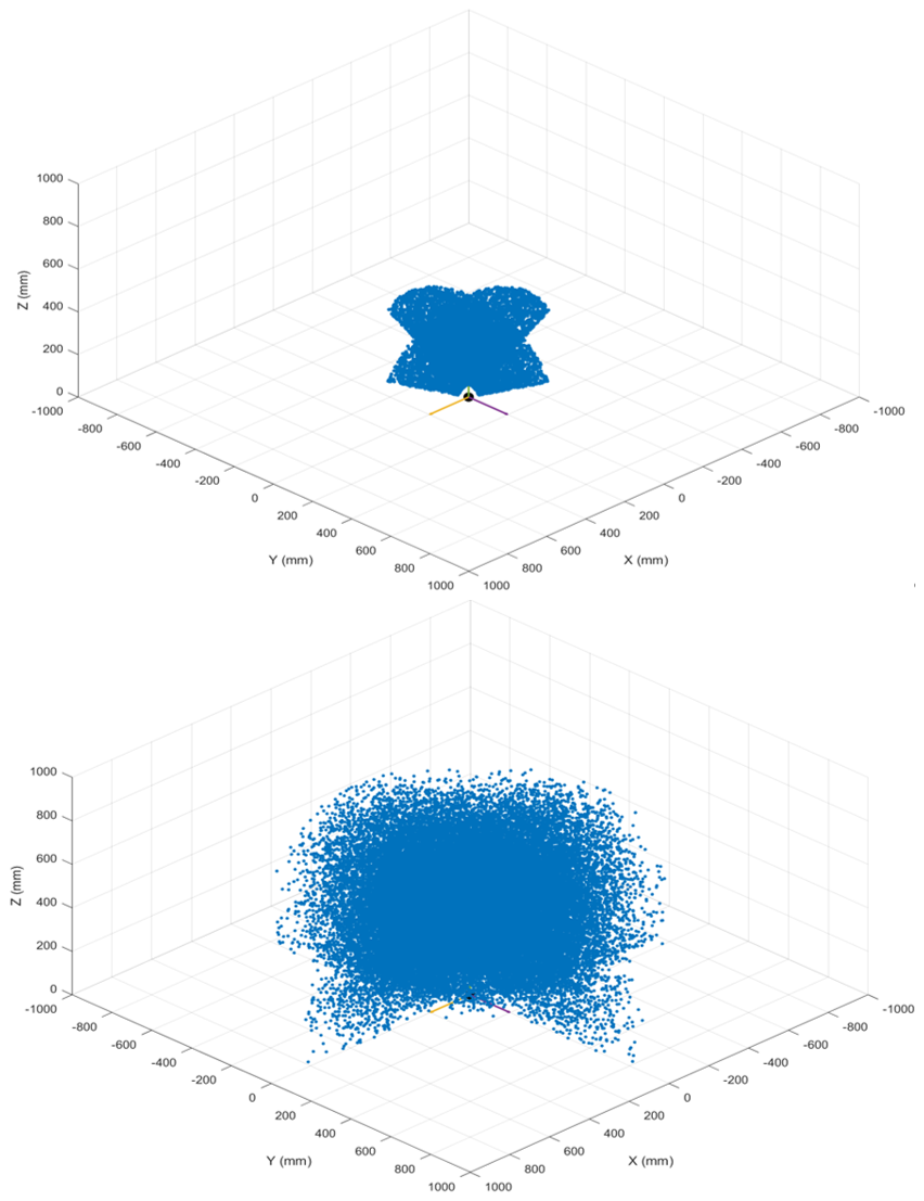
Figure 7Workspace of the moving platform of a single-segment parallel capture mechanism and workspace of the moving platform of the two-segment parallel capture mechanism.
8.1 Simulation verification
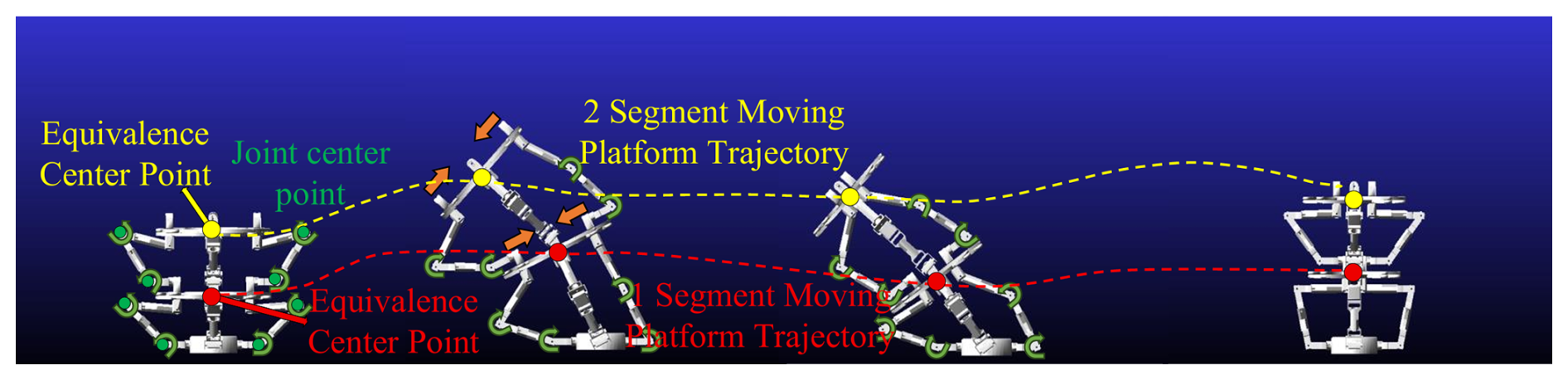
The forward- and lateral-capture processes include target detection, extension toward the target, closure of the double-loop folding platform to achieve grasping, and finally bringing the target back to the working satellite. Each single parallel capture mechanism is equipped with five drives, which can be arbitrarily configured at the Ani and Cni joints of the branch chains; the positions of Ani and Cni are shown in the Fig. 5. Based on the previously obtained feasibility analysis, a simulation model was established to verify the operability of the mechanism. Forward-capture simulation is conducted; in this simulation, the drive positions of each segment are configured at An1, An2, An3, An4, and Cn1. The simulation process is shown in Fig. 8.
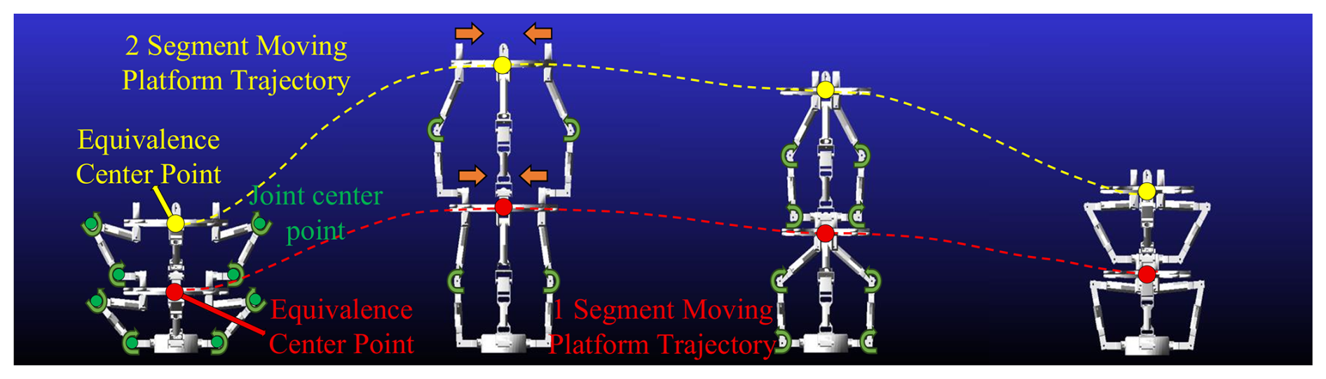
As shown in the Fig. 8, the trajectory of the second-segment double-loop folding expansion platform is significantly longer than that of the first-segment one. A lateral-capture simulation was also conducted, and the results are shown in Fig. 9.
The simulations verify that the mechanism can successfully perform the capture operation, confirming the rationality of the multi-segment serial–parallel spatial closed-chain mechanism design.
8.2 Prototype verification
Subsequently, the development of a prototype will be carried out. Servo motors are used as driving joints; given that the prototype is composed of two segments, the selected servo parameters are as follows: eight dual-axis servos with a torque of 25 kg are adopted for the first section, and eight dual-axis servos with a torque of 20 kg are adopted for the second segment. Prototype rods are fabricated using 3D-printed materials according to the dimensional parameters, the diagonal center distance of the fixed platform is set as R0=290 mm, the link lengths of the mechanism's mechanical arm are l1=160 mm and l2=155 mm, and the link radius dimension of the dual-ring deployable-folding platform is r=82 mm.
To ensure smooth motion, a redundant actuation method is adopted. Each parallel capture mechanism is driven by eight drive joints, with the drive joint installation positions being the same as those in the simulation. By controlling the driving joints, the prototype can perform capture operations in multiple modes. Among them, the prototype is shown in Fig. 10.
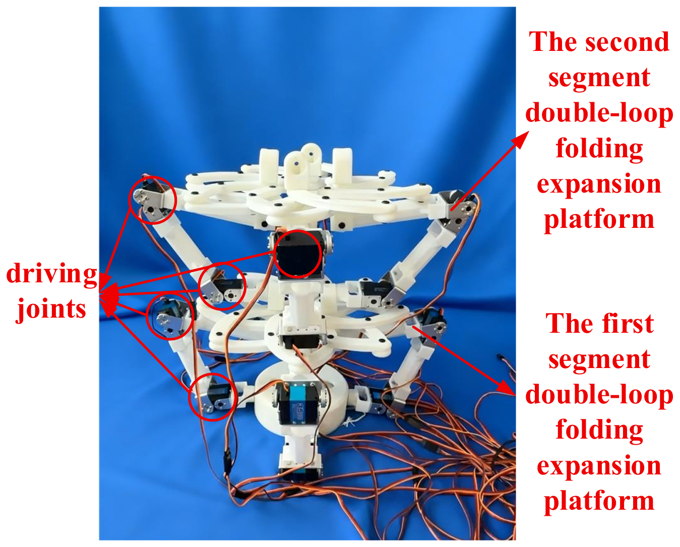
Figure 10Prototype of a multi-segment series-parallel spatial closed-loop capture mechanism based on bionic principles.
To improve the engineering completeness, a brief control strategy is further discussed to clarify how the redundant actuation and the multi-segment serial connection are coordinated during on-orbit capture tasks. Since the fixed platform of each segment shares the same coordinate system with the moving platform of the previous segment (Fig. 3), the overall control problem can be formulated as a hierarchical synchronization of segment-level motions. Specifically, a supervisory kinematic layer generates the desired pose of each segment's moving platform according to the target-relative capture phases, including extension toward the target, enclosure by folding, and retrieval. The corresponding joint commands are then obtained by solving the inverse-position relations of each segment while enforcing inter-segment pose consistency; i.e., the commanded motion of segment n is referenced to the actual output pose of segment (n−1) to avoid accumulation of kinematic mismatch during serial deployment.
Regarding actuation redundancy, the prototype adopts eight drive joints for each parallel capture mechanism, although the single parallel module has 5 independent DOFs. This redundancy can be utilized for fault tolerance and load sharing. In practice, the joint space commands can be computed using a constrained optimization or weighted least-norm mapping, where the primary task tracks the desired end-platform pose, and the secondary task redistributes actuation efforts to avoid joint limits and reduce internal stress. Under a single-joint degradation or temporary drive loss, the remaining actuators can maintain the required motion by reconfiguring the redundancy resolution, thereby improving capture reliability.
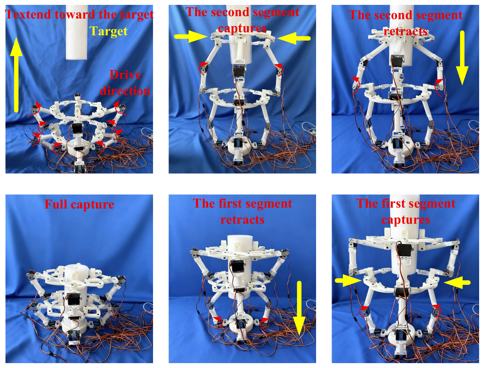
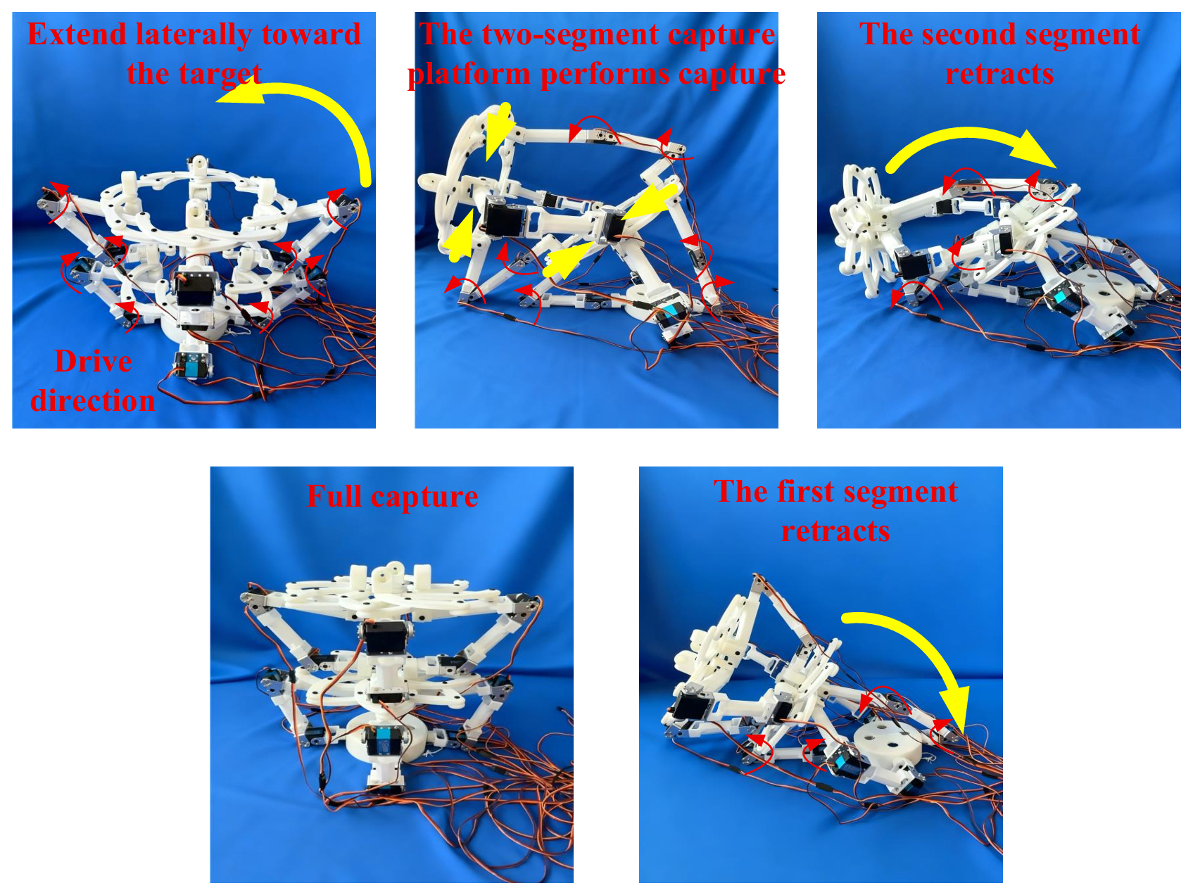
Synchronization between segments is ensured by a time-stamped command sequence with segment-wise phase locking: first, all segments execute a coordinated extension with bounded velocity to keep the Jacobian well-conditioned; second, the double-loop folding expansion platforms perform enclosure with synchronized radial contraction to guarantee simultaneous contact establishment; and, finally, the retrieval phase is controlled in a primary–secondary manner, where the proximal segment acts as the primary reference, and distal segments follow with pose error feedback, ensuring stable closed-chain motion transmission throughout the multi-segment structure. After establishing the above coordination principle, the forward-capture process of the mechanism is shown in Fig. 11, and the lateral-capture process is depicted in Fig. 12.
The prototype experiments verify that the multi-segment serial–parallel spatial closed-chain capture mechanism provides a high folding ratio, enables efficient folding and storage, supports directional and controllable extension, achieves multi-mode capture, and balances high DOFs with system expandability.
It should be noted that the present simulations and prototype tests mainly verify the motion feasibility and operational correctness of the proposed multi-segment serial–parallel spatial closed-chain capture mechanism. Quantitative evaluation of practical grasping performance, such as grasping force, payload capacity, and structural stiffness, requires additional modeling of force transmission and compliance, as well as dedicated measurement or finite-element verification, which is beyond the current kinematic-focused scope. Nevertheless, the proposed Jacobian-based formulation provides a direct basis for quantitative performance evaluation: under quasi-static conditions, the achievable grasping force can be estimated from actuator torque limits via the Jacobian transpose, while the end-effector stiffness can be obtained by combining the mechanism Jacobian with link and joint compliance models.
In future work, we will establish a force–stiffness–payload evaluation framework by incorporating structural strength constraints and conducting multi-condition prototype tests to provide quantitative evidence for on-orbit capture practicality.
This paper proposes a multi-segment serial–parallel spatial closed-chain capture mechanism inspired by bionic principles. First, a single parallel capture mechanism with a core architecture composed of a double-loop folding expansion platform and a four-URU four-branch parallel mechanism is designed, and a multi-segment serial–parallel spatial closed-chain capture mechanism is obtained through series connection. Second, the DOF of the mechanism is calculated using the null-space method, followed by kinematic analysis and singularity analysis of the multi-segment serial–parallel capture mechanism. The workspace of the mechanism is then verified. Finally, simulations and a prototype model are used to verify the motion feasibility of the multi-segment serial–parallel spatial closed-chain capture mechanism. The proposed design enables stable long-distance target capture in space, offering a promising solution for failed-satellite recovery and space debris removal.
Future work will primarily focus on the systematic investigation of inertia, vibration, and impact effects. Meanwhile, subsequent research efforts will be devoted to enhancing the capture stability of the mechanism, advancing the lightweight structural design of its key components, and further validating the long-term operational reliability of the whole mechanism through multi-condition prototype testing, all of which are intended to provide robust technical support for the practical on-orbit capture of non-cooperative space targets.
All data generated or analyzed during this study are included in this published article.
XY was responsible for the mechanism analysis and organized the structure of the paper. RL was responsible for the mechanism design. YY, XS, and ZC conceived and developed the overall concept of the paper. XY, RL, XS, XZ, and ZC contributed to the writing and review of the initial paper.
The contact author has declared that none of the authors has any competing interests.
Publisher's note: Copernicus Publications remains neutral with regard to jurisdictional claims made in the text, published maps, institutional affiliations, or any other geographical representation in this paper. The authors bear the ultimate responsibility for providing appropriate place names. Views expressed in the text are those of the authors and do not necessarily reflect the views of the publisher.
This research has been supported by the National Natural Science Foundation of China, Youth Science Fund Project (grant no. 52505027) and the Natural Science Foundation of Shandong Province (grant no. ZR2025QC545).
This research has been supported by the National Natural Science Foundation of China, Youth Science Fund Project (grant no. 52505027) and the Natural Science Foundation of Shandong Province (grant no. ZR2025QC545).
This paper was edited by Zhiwei Zhu and reviewed by two anonymous referees.
An, Q., Zhang, Y., Huang, X., Li, H., and Xia, X.: Impedance control in serial-parallel hybrid space robots for assembly operations, Acta Astronaut., 232, 316–329, https://doi.org/10.1016/j.actaastro.2025.03.016, 2025.
Bigdeli, M., Srivastava, R., and Scaraggi, M.: Mechanics of Space Debris Removal: A Review, Aerospace, 12, 277, https://doi.org/10.3390/aerospace12040277, 2025.
Fallahiarezoodar, N. and Zhu, Z. H.: Review of Autonomous Space Robotic Manipulators for On-Orbit Servicing and Active Debris Removal, Space: Science & Technology, 5, 0291, https://doi.org/10.34133/space.0291, 2025.
Flores-Abad, A., Ma, O., Pham, K. D., and Ulrich, S.: A review of space robotics technologies for on-orbit servicing, Prog. Aerosp. Sci., 68, 1–26, https://doi.org/10.1016/j.paerosci.2014.03.002, 2014.
Forshaw, J. L., Aglietti, G. S., Navarathinam, N., Kadhem, H., Salmon, T., Pisseloup, A., Joffre, E., Chabot, T., Retat, I., Axthelm, R., Barraclough, S., Ratcliffe, A., Bernal, C., Chaumette, F., Pollini, A., and Steyn, W. H.: RemoveDEBRIS: An in-orbit active debris removal demonstration mission, Acta Astronaut., 127, 448–463, https://doi.org/10.1016/j.actaastro.2016.06.018, 2016.
Gao, C., Huang, H., Li, B., and Jia, G.: Design of a truss-shaped deployable grasping mechanism using mobility bifurcation, Mech. Mach. Theory, 139, 346–358, https://doi.org/10.1016/j.mechmachtheory.2019.05.003, 2019.
Gao, C., Huang, H., Li, B., and Jia, G.: Design and analysis of a novel large-span two-fold deployable mechanism, Mech. Mach. Theory, 154, 104013, https://doi.org/10.1016/j.mechmachtheory.2023.105352, 2023.
Jia, G., Li, B., Huang, H., and Wu, Y.: Analysis of an underactuated biomimetic Octopus hand for grasping space non-cooperative objects, IEEE Robot., 9, 041011, https://doi.org/10.1109/CBS.2017.8266065, 2017.
Kaiser, C., Sjöberg, F., Delcura, J. M., and Eilertsen, B.: SMART-OLEV – An orbital life extension vehicle for servicing commercial spacecrafts in GEO, Acta Astronaut., 63, 400–410, https://doi.org/10.1016/j.actaastro.2007.12.053, 2008.
Li, G., Huang, H., and Guo, H.: Design, analysis and control of a novel deployable grasping manipulator, Mech. Mach. Theory, 138, 182–204, https://doi.org/10.1016/j.mechmachtheory.2019.03.043, 2019.
Liu, Y., Xu, Y., Lü, Y. P., and Song, W.: Kinematic Performance Analysis and Scale Optimization of a Fully Symmetric 4-URU Parallel Mechanism, J. Mechan. Trans., 43, 35–40, https://doi.org/10.16578/j.issn.1004.2539.2019.07.007, 2019.
Ma, B., Jiang, Z., Liu, Y., and Xie, Z.: Advances in Space Robots for On-Orbit Servicing: A Comprehensive Review, Adv. Intell. Syst., 5, 2200397, https://doi.org/10.1002/aisy.202200397, 2023.
Meng, Z. J., Huang, P., Lu, Y. B., and Hu, Y. X.: Applications and development of space tether in on-orbit servicing, J. Astronaut., 40, 1134–1145, https://doi.org/10.3873/j.issn.1000-1328.2019.10.004, 2019.
Sharf, I., Thomsen, B., Botta, E. M., and Misra, A. K.: Experiments and simulation of a net closing mechanism for tether-net capture of space debris, Acta Astronaut., 139, 332–343, https://doi.org/10.1016/j.actaastro.2017.07.026, 2017.
Tang, J., Xia, Z., Chen, Y., and Sun, Y.: Structural designs of novel deployable polyhedral grippers for noncontact capturing missions, Acta Astronaut., 170, 203–213, https://doi.org/10.1115/1.4063968, 2024.
Teoh, Z. E., Wilcox, Z. C., Xu, L., Costello, C. P., and Wood, R. J.: Rotary-actuated folding polyhedrons for midwater investigation of delicate marine organisms, Sci. Robot., 5, eabc6243, https://doi.org/10.1126/scirobotics.aat5276, 2018.
Tsiotras, P., King-Smith, M., and Ticozzi, L.: Spacecraft-mounted robotics, Annu. Rev. Control Robot. Auton. Syst., 6, 335–362, https://doi.org/10.1146/annurev-control-062122-082114, 2023.
Wang, S., Huang, H., Jia, G., Li, B., and Guo, H.: Design of a novel three-limb deployable mechanism with mobility bifurcation, Mech. Mach. Theory, 172, 104789, https://doi.org/10.1016/j.mechmachtheory.2022.104789, 2022.
Wei, G., Ding, X., and Dai, J. S.: Mobility and Geometric Analysis of the Hoberman Switch-Pitch Ball and Its Variant, J. Mech. Robot., 2, 031010, https://doi.org/10.1115/1.4001730, 2010.
Xia, Z., Tang, J., Chen, Y., and Sun, Y.: An Omnidirectional Encircled Deployable Polyhedral Gripper for Contactless Delicate Midwater Creatures Sampling, IEEE Robot. Autom. Lett., 5, 3849–3856, https://doi.org/10.1002/adem.202201416, 2020.
Xu, Y.: A closed-chain deployable claw for satellite capture, J. Mech. Robot., 15, 31–104, https://doi.org/10.3969/j.issn.1005-2895.2022.04.005, 2023.
Zhang, Y., Qian, Z., Huang, H., Yang, X., and Li, B.: A snake-inspired swallowing robot based on Hoberman's linkages, J. Mech. Robot., 14, 011005, https://doi.org/10.1115/1.4054308, 2022.
- Abstract
- Introduction
- Configuration design
- DOF analysis
- Inverse-position solution
- Forward-position solution
- Singularity analysis
- Workspace verification
- Simulation and prototype verification?
- Conclusions
- Appendix A:
- Code and data availability
- Author contributions
- Competing interests
- Disclaimer
- Acknowledgements
- Financial support
- Review statement
- References