the Creative Commons Attribution 4.0 License.
the Creative Commons Attribution 4.0 License.
 | 11 Nov 2025
The kinematics analysis and improvement of the 3T1R 4-PUU parallel mechanism using the whale optimization algorithm
Kai Wen
Xiaoning Zhou
Andong Jiang
Jie Li
This paper focuses on the 4-PUU parallel mechanism with Schönflies motion, investigating its kinematic analysis and utilizing intelligent algorithms to solve its forward kinematics equations. Using screw theory as the mathematical framework, the number and nature of the degrees of freedom of the 4-PUU parallel mechanism are analyzed, proving that the mechanism can achieve 3T1R motion. The forward and inverse position kinematics equations are established with link lengths as constraints, and the velocity and acceleration equations of the mechanism are derived using the vector method. The forward kinematics equations of the mechanism are transformed into an unconstrained optimization problem, which is solved using an improved beluga whale optimization (BWO). To enhance the uniformity of the initial population distribution, a chaotic-opposition-based learning initialization strategy is introduced. Additionally, an elite strategy and a golden-sine-based position update mechanism are incorporated to improve the optimization capability of BWO. The integration of these strategies results in an enhanced optimization algorithm with superior global search ability. Given the mechanism's dimensional parameters, theoretical and motion simulations are conducted using MATLAB and Adams. The results indicate that the motion simulation curves from Adams closely match the numerical simulation curves from MATLAB, validating the theoretical derivation. Building on this, the improved beluga whale optimization (IBWO) algorithm, along with comparison algorithms (DEb1, ABC, PSO), is applied to solve the forward kinematics equations for interpolation points along the simulated trajectory. Numerical experiments demonstrate that IBWO outperforms the other comparison algorithms in solving the problem efficiently and accurately.
- Article
(2877 KB) - Full-text XML
- BibTeX
- EndNote


Compared to 6-degree-of-freedom (DOF) parallel mechanisms (PMs), those with fewer DOFs offer advantages such as simpler structure, fewer drives, and easier control and have gradually gained widespread attention from both academia and industry. Among them, the 3T1R (T representing translation and R representing revolute) PM is widely used in practical engineering applications such as packaging and sorting (Zhu et al., 2022), welding (Wen et al., 2024), assembly (Li et al., 2021), and rehabilitation (Shi et al., 2024).
The original SCARA – with 3T1R DOF (where T and R represent translational and rotational degrees of freedom, respectively) – is an extension of the 3-DOF Delta robot. An additional UPU chain was incorporated between the moving and fixed platforms to provide rotation about the z axis. The kinematic analysis, performance analysis, error compensation, and trajectory planning of the PM are all based on the integration of its configuration. Therefore, it is evident that the configuration synthesis of the SCARA of PM forms the foundation for subsequent theoretical analysis and structural design.
The configuration synthesis of SCARA PMs has shown significant research achievements. Company et al. (2003) designed a structure with both symmetric and asymmetric H4 PM based on the motion used to generate Schönflies displacement subgroups. Yang et al. (2017) proposed a configuration synthesis method for a 3T1R PM with a variable rotation axis based on screw theory. Salgado et al. (2008) used the theory of groups of displacements, based on the H4, I4 (Krut et al., 2003), and Par4 (Nabat et al., 2005) mechanisms. Li et al. (2014) replaced the original parallelogram chains with R(SS)2 chains, introducing the Cross IV series PMs, which were later industrialized. Staicu et al. (2018) proposed a fully symmetric X4 PM where each of the four chains is composed of R(SS)R, resulting in improved dynamic characteristics and simplified manufacturing. Wen et al. (2024) designed a 2PUU-2PSS PM with an axially symmetric structure based on screw theory. Xie et al. (2013), using Grassmann line geometry and the Atlas method, designed a class of PMs with 3T1R (1T3R, 2T2R, and 3T1R) motion.
Kinematic analysis of PMs forms the foundation for error compensation, trajectory planning, and workspace analysis. It primarily consists of forward kinematics analysis and inverse kinematics analysis. For coupled PMs, the inverse kinematics analysis typically involves decoupling the equations, while the forward kinematics usually leads to a coupled nonlinear system of equations. The solution to the forward kinematics equations of coupled PMs is mainly divided into analytical method and numerical method. Analytical methods involve eliminating unknowns and reducing higher-order equations to first-order equations. By solving the first-order equations and performing inverse substitution of the results, a high-precision solution to the forward kinematics can be obtained. However, this method is specific to certain configurations and lacks generality. Numerical methods, on the other hand, include numerical iteration, machine learning, and intelligent algorithms, which can be applied to a wider range of mechanisms and offer more flexibility in handling complex kinematic problems.
Wen et al. (2024) proposed a mean-based dual-strategy differential evolution algorithm for solving the forward kinematics equations of the 2PUU-2PSS PM. It was demonstrated that the performance of this algorithm surpasses that of comparison algorithms such as IABC and DEr1 through numerical examples. Liu et al. (2019) combined genetic algorithms and backpropagation (BP) neural networks to solve the forward kinematics equations of the Delta robot, with results showing better performance than traditional BP neural networks. Wu et al. (2024) introduced an improved backpropagation neural network for solving the forward kinematics equations of redundant PMs, and experimental results indicated a significant improvement in solution accuracy. Wen et al. (2023) proposed a time-varying differential evolution algorithm for solving the multiple solution problem of forward kinematics equations in PMs. Using PMs with 3 to 6 DOF as examples, the feasibility and versatility of the algorithm were verified.
This paper is based on the configuration synthesis of PMs and utilizes screw theory to design a 4-PUU PM with a fully symmetric structure, which the workspace is unaffected by the vertical direction. The structure and kinematic analysis of the 4-PUU PM are presented in the following chapters: Sect. 2 provides a structural description of the 4-PUU PM and analyzes its degrees of freedom using screw theory. Section 3 derives the kinematic equations of the mechanism using vector and differentiation methods. Section 4 introduces an improved whale optimization algorithm (IBWO) to solve the forward kinematics equations of the 4-PUU PM. Section 5 verifies the correctness of the kinematic formula derivations through motion simulations using Adams software and validates the performance of the IBWO algorithm through numerical examples. Section 6 concludes the paper and outlines future research directions.
2.1 Structural description
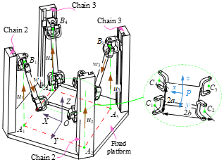
The 4-PUU PM is shown in Fig. 1. This mechanism mainly consists of a moving platform, a fixed platform, and four identical structural branches. Each branch is composed of a prismatic pair (P) and universal pair (U), which are rotational pairs with axes perpendicular to each other. The topology of the branch can be represented as SCO{-P1∥R2⊥R3∥R4⊥R5}.That is, starting from the fixed platform, the axis of the moving pair 1 is parallel to the axis of the rotating pair 2, the axis of the rotating pair 2 is perpendicular to the axis of the rotating pair 3, the axis of the rotating pair 3 is parallel to the axis of the rotating pair 4, the axis of the rotating pair 4 is perpendicular to the axis of the rotating pair 5, and the axis of the rotating pair 5 is perpendicular to the moving platform. In the PUU chain, the intersection of the axis of the pair (P) with the fixed platform is denoted as . The center of the first universal joint intersects the axis of the pair at point Bi, and the center of the second universal joint intersects the moving platform at point Ci. To avoid the initial singularity of the mechanism, the fixed platform is set as a square with the points Ai lying on a circle with radius . The moving platform is set as a rectangle with side lengths of 2a and 2b.
-
A fixed coordinate system {f}: OXYZ is established on the fixed platform, where O is the geometric center of the fixed platform. The OX axis is perpendicular to A1A4 and passes through its midpoint, the OY axis is perpendicular to A1A2 and passes through its midpoint, and the OZ axis is perpendicular to the fixed platform and points vertically upwards.
-
A moving coordinate system {m}: Pxyz is established on the moving platform, where P is the geometric center of the moving platform. The Px axis is perpendicular to C1C4 and passes through its midpoint, the Py axis is perpendicular to C1C2 and passes through its midpoint, and the Pz axis is perpendicular to the moving platform and points vertically upwards.
2.2 Analysis of DOF
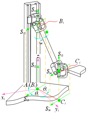
The branch coordinate system is established as shown in Fig. 2: Ai–xiyizi, where the zi axis coincides with AiBi and points toward Bi, the yi axis coincides with AiO and points toward O, and the xi axis is determined by the right-hand rule. The angle between the revolute pair R3 and the xi axis is θI, and the angle between the link BiCi and the axis of the prismatic joint P is ζi. Thus, in the branch coordinate system, the motion screw of the PUU branch can be expressed as
where cosθi=cθi, sinθi=sθi, cosξi=cξi, and sinξi=sξi.
Therefore, the constraint screw of the PUU chain can be expressed as
Equation (2) represents a reciprocal screw pair, which indicates that the branch constrains the moving platform's rotation around the direction parallel to (sinθi, −cosθi, 0). The constraints imposed by the four symmetrically distributed PUU branches on the moving platform can be expressed using the two reciprocal screws and . Clearly, these two reciprocal screws are linearly dependent. Therefore, a linear combination of the following two reciprocal screws can be used to obtain
According to Eq. (3), the constraint screws applied to the moving platform by the four branches are
$CWS,1 and $CWS,2 represent the constraint wrenches around the X axis and Y axis, respectively, applying rotational constraints around the X and Y axes to the moving platform, thus causing the platform to lose its rotational freedom around the X and Y axes. Therefore, the 4-PUU PM proposed in this paper has 4 DOF(3TIRZ). In general configurations (except for singular poses), the motion pairs of each branch maintain their original geometric relationships due to structural constraints. The coordinate relations shown in Fig. 2 can still be established, and the resulting motion screws and the computed reciprocal screws remain unchanged. The constraint wrenches of the four reciprocal screw systems remain in the same plane, and their linear independence and rank remain constant. That is, the virtual constraints of the mechanism remain unchanged. Thus, the DOFs correspond to full rotational freedom.
3.1 Forward and inverse kinematics analysis
3.1.1 Forward kinematics
The forward kinematics solution of the mechanism is to calculate the output position P= (XP, YP, ZP) and the attitude angle γ of the moving platform's reference point P, given the scale parameters of the mechanism and the input link lengths hi (for i=1, …, 4) of the prismatic joints. The structural parameters of the platform are set as , and the coordinates of point Ai in the frame {f} are defined as
The coordinate vector of point Ci in the frame {m} is
The unit vector of the axis of the driving arm AiBi in the frame {f} is
Assume the coordinate vector of the reference point P on the moving platform in the fixed frame {f} is
The attitude matrix of the moving platform is
Then, the coordinate vector of point Ci(i=1, …, 4) in the fixed coordinate system {f} is
The unit vector of the axis of the moving arm BiCi in the fixed frame {f} is
The constraint equation of the link BiCi is
According to Eq. (11), we can obtain
Equation (12) is a system of coupled nonlinear equations, which can be solved using both numerical methods and analytical methods. The analytical method involves substitution and elimination to obtain a single high-order equation. By solving this high-order equation and performing backward substitution, a high-precision forward kinematics solution for the mechanism can be obtained. However, this method has limited applicability and is only suitable for special configurations of PMs. The numerical method, on the other hand, solves the equations using intelligent algorithms or numerical iteration, offering advantages such as simplicity and efficiency. Therefore, in this paper, a numerical method is employed to solve the forward kinematics equations, as detailed in Sect. 4.
3.1.2 Inverse kinematics
The inverse kinematics analysis of the mechanism involves the process of solving for the input hi given the output position and orientation of the mechanism (XP, YP, ZP, γ). Thus, it can be deduced that, according to Eq. (12), we obtain
In the equation, λij is a coefficient (; ), and its expression is
3.2 Kinematic velocity analysis
Let the inputs of the four driving joints of the mechanism be h=(h1, h2,h3,h4)T, the output quantities of the moving platform be X=(XP, YP,ZP, γ)T, the input velocities of the four driving joints be , , , , the output velocities of the moving platform be , , , and the angular velocity output vector of the moving platform be .
Taking the derivative of Eq. (11) with respect to time t, we get
By simplifying this, we obtain
Let and take :
It can be seen that Eq. (16) can be rewritten as
If Jout is non-singular, then
If Jin is non-singular, then
Equations (22) and (23) are the forward and inverse velocity solutions of the 4-PUU PM, respectively.
3.3 Acceleration analysis
Let the input accelerations of the mechanism's driving joints be , , , and the output acceleration of the moving platform be , with the output angular velocity being . Taking the derivative of equation with respect to time t, we get
If we denote , then we have .
It can be seen that Eq. (20) can be simplified to
If Jout is non-singular, then
If Jin is non-singular, then
Equations (22) and (23) are the forward and inverse acceleration solutions of the 4-PUU PM, respectively.
4.1 Mathematical modeling and beluga whale optimization (BWO)
4.1.1 Mathematical modeling
When solving the forward kinematics (Eq. 12) of the PM using a swarm intelligence algorithm, it is necessary to first convert it into an unconstrained optimization problem and then use the swarm intelligence algorithm to iteratively optimize the unconstrained optimization equation. Thus, we define x=(x1, x2, x3, x4)T= (XP, YP, ZP, γ)T, and Eq. (12) can be transformed into
The nonlinear system of equations in Eq. (24) can be transformed into an unconstrained optimization problem as follows: .
4.1.2 Beluga whale optimization (BWO)
The BWO (Zhong et al., 2022) is a bio-inspired optimization algorithm that simulates the hunting behavior of the beluga whale. The BWO algorithm has characteristics such as a simple structure, easy expandability, few control parameters, and strong robustness. The main process of this algorithm includes the following steps: population initialization, encircling prey, bubble-net attacking, and searching for prey.
-
Population initialization
The initialization of the population in the BWO is similar to other optimization algorithms. It involves generating an initial population of NP individuals (where NP is the population size) randomly within the search space of the optimization variables. Specifically, the process is as follows:
In the equation, xmin,d and xmax,d represent the lower and upper bounds of the dth variable, respectively. Here, d=1, 2, …, D, where D is the total number of decision variables (the dimensionality of the search space).
-
Encircling prey
In the BWO, since the optimal solution in the search space is not known in advance, it is assumed that the best solution obtained so far is the target prey or an approximation of the global optimum. Once the optimal solution's position is determined, the other whale individuals in the population move towards this optimal position. The position update for each whale is then given by the following equation:
In the equation, t represents the current iteration number, x(t) denotes the position of the whale population at the tth iteration, x*(t) is the position of the best solution (prey) in the whale population at iteration t, A⋅τ represents the update step size for the whale population, and A and τ are the update coefficients. Their specific expressions are as follows:
In the equation, r1 and r2 are random numbers between [0,1]; this convergence factor is used to balance the global search ability and local search ability. It is given by the following formula: , where T is the maximum number of iterations.
-
Bubble net attack
In the BWO, the bubble net attack is a crucial phase that combines two different movement strategies: shrink encircling and spiral updating. These two strategies allow the whales to explore the solution space globally and locally, respectively. The choice of which strategy to use is determined by a probability p, which controls the switching between the two methods. The specific operations are as follows:
In the equation, b is the spiral shape parameter; τ′ is the Euclidean distance between the current global best solution and the current whale's position; l is a random number uniformly distributed between [−1,1], used to introduce randomness into the movement; and p is a random number uniformly distributed between [0,1], which controls the probability of selecting a specific update method (shrink encircling or spiral updating).
-
Search for prey
The BWO updates the positions of the whales based on the distance between the individual whales, thereby performing a random search. When , the BWO algorithm randomly selects a whale position as the target whale , and the other whales update their positions relative to this target in search of a better prey. The updated formula is as follows:
In the equation, τ” represents the step size coefficient, .
4.2 Improved beluga whale optimization (IBWO)
4.2.1 Chaos-inspired backward learning population initialization
The initial population of the basic differential evolution algorithm is randomly generated using Eq. (25), which can lead to an uneven distribution and clustering of the generated initial population. The use of chaotic mapping can effectively address the issue of population initialization. Commonly used chaotic maps include the Kent map (Xiang et al., 2007), Circle map (Arora et al., 2019), and Logistic map (Herbadji et al., 2019). According to the reference (Sankalap et al., 2019), the Circle map generates a more evenly distributed initial population compared to other chaotic maps. However, the initial population generated by the Circle map still tends to be denser in the range [0.2, 0.6] compared to other values. Therefore, in this paper, the Circle map is improved to achieve a relatively uniform distribution across the entire solution space. The improved Circle map formula is as follows:
In the equation, n=1,2,…, NP; when n=2, rand (1,D). Combining with Eq. (25), the initial population is generated using the following method:
As shown in Figs. 3–5 to clearly and intuitively demonstrate the advantages of the improved Circle map, the initial population distributions for random initialization, Circle map, and improved Circle map are plotted for n=1000, along with a frequency statistical analysis.
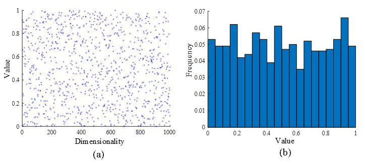
Figure 3Distribution diagram of rand population initialization methods showing (a) value and (b) frequency.
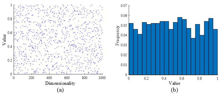
Figure 4Distribution diagram of circle map population initialization methods showing (a) value and (b) frequency.
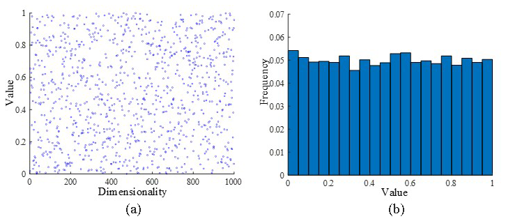
Figure 5Distribution diagram of improved circle map population initialization methods showing (a) value and (b) frequency.
As shown in Fig. 3, the improved Circle chaotic map results in a more evenly distributed chaotic value. Therefore, the improved Circle chaotic map is used to generate the initial population, which enhances the population diversity and, in turn, improves the optimization ability of the algorithm.
Backward learning can improve the quality and diversity of the population solutions. However, the distance between the solutions generated by backward learning and the current solution is fixed, which is detrimental to population diversity and lacks a certain degree of randomness. Therefore, based on the improved Circle map, a dynamic backward learning strategy is employed to further increase population diversity and the number of elite individuals, thereby expanding the search range of the algorithm. The dynamic backward learning strategy is as follows:
Combining Eqs. (32) and (34), for the minimization optimization problem, the chaos-backward learning population initialization can be expressed as
4.2.2 Elite strategy
According to Eq. (29), the BWO algorithm updates positions based on the current optimal position of the whale. If the current optimal whale position becomes trapped in a local optimum, all the whales will converge around the local optimal individual, causing the algorithm to stagnate. In the gray wolf optimization algorithm (GWO), to increase population diversity, a hierarchical system is proposed. This involves applying weighted processing to the three individuals with the best fitness values in the current population, using them as the current optimal position. This approach helps to avoid the risk of the population getting trapped in a local optimum.
Based on the hierarchical system of the GWO algorithm (Ghalambaz et al., 2021), this paper introduces the concept of an elite pool. Specifically, the three best individuals in the population, along with the weighted individuals of high quality, are stored in the elite pool. During the position update process, an individual is randomly selected from the elite pool to serve as a guide, enhancing the algorithm's ability to escape local optima. The elite strategy is as follows:
are the top three individuals ranked in descending order based on their fitness values. is considered to denote the weighted individuals, and the calculation method is as follows:
4.2.3 Incorporating the golden sine position update strategy
The BWO algorithm uses the spiral position update strategy from Eq. (30). During the later stages of the algorithm, all individuals in the population gather near the optimal individual, which accelerates the convergence speed of the algorithm but can lead to getting stuck in local optima, resulting in poor population diversity. The golden sine algorithm (Golden-SA) is a new metaheuristic algorithm (Lu and Zhang, 2023) that has strong global search capabilities. Golden-SA introduces a golden ratio coefficient in its position update process, allowing the algorithm to thoroughly search regions that can produce excellent solutions during each iteration, thereby accelerating the convergence speed and escaping local optima. Therefore, when updating positions in the BWO algorithm, the position update strategy from Golden-SA can be adopted to enhance the global search ability and accelerate its convergence speed. Thus, the new position update strategy is as follows:
In the equation, r1 and r2 are random numbers between [0, 1]; R1 is a random number between [0, 2]; and ε1 and ε2 are golden ratio coefficients, and their specific expressions are
In the equation, Γ is the golden ratio coefficient, and its value is .
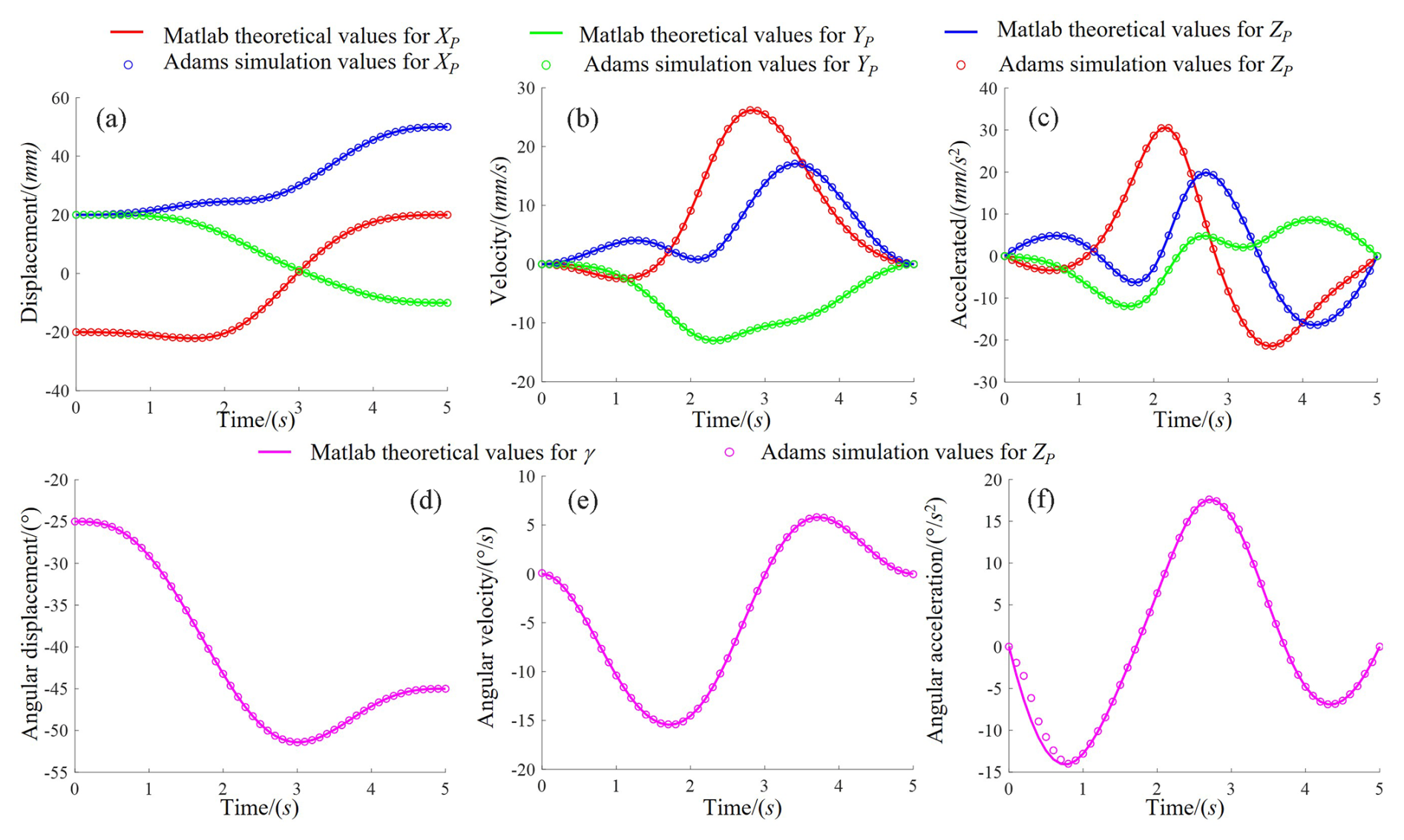
Figure 6Comparison between MATLAB theoretical calculations and adams simulation analysis results showing (a) displacement, (b) velocity, (c) acceleration, (d) angular displacement, (e) angular velocity, and (f) angular acceleration.
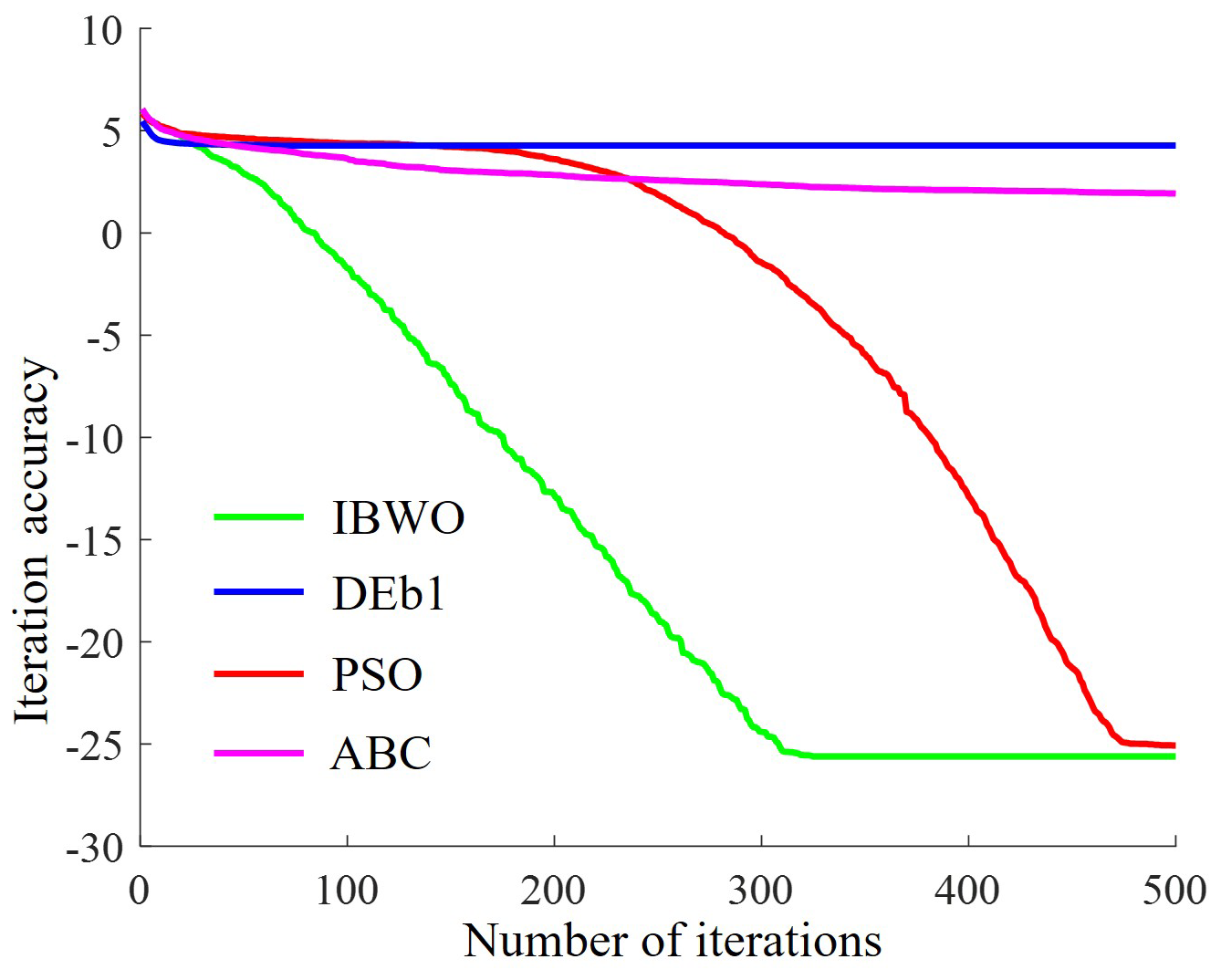
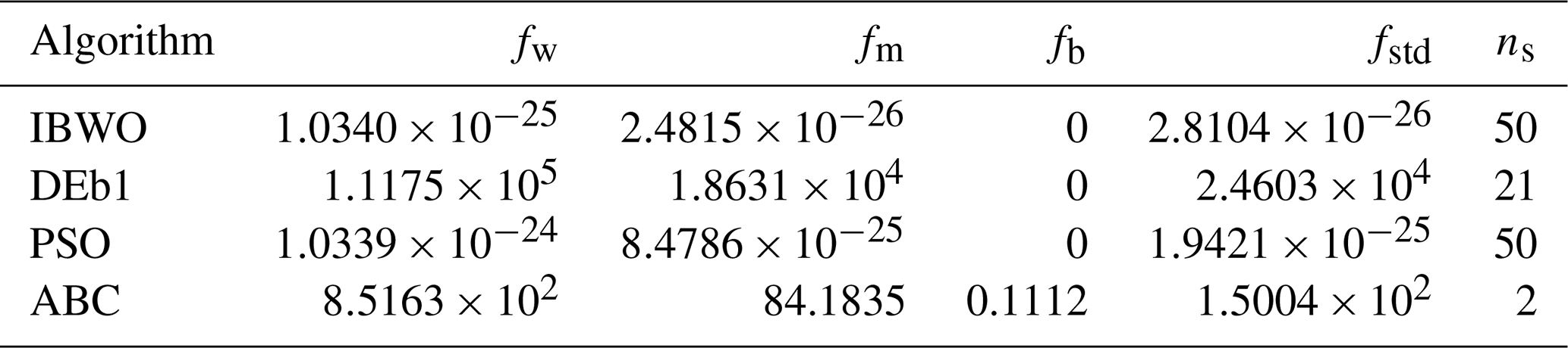
Table 2Performance statistical results of the four algorithms.
5.1 Kinematic simulation verification
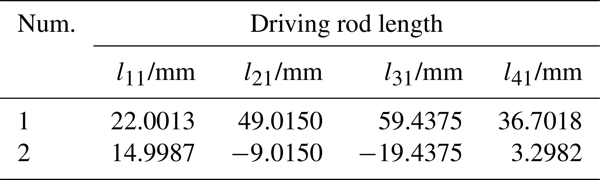
In this section, MATLAB numerical examples and Adams motion simulation are used together to verify the correctness of the kinematic equations derived for the 4-PUU PM. First, a numerical example of the mechanism's position analysis is provided. The mechanism's scale parameters are set as R=38, a=18.75, b=12.5, l=43 mm. The initial position of the fixed platform is set as (XP, YP, ZP, , 20, 20 mm, −25°)T; the final position of the moving platform is set as (XP, YP, ZP, γ)T=(20, −10, 50, −45°)T. The initial and final positions of the moving platform are substituted into Eq. (13) to determine the corresponding sub-configurations of the mechanism (hi≥{f}ZCi) and the input rod lengths. The change in the driving pair of each limb is calculated as Δhi= (65.3012, 31.5674, 13.5590, 48.1959). To avoid motion shocks caused by sudden changes in velocity and acceleration, which could affect the kinematic simulation results, the four moving driving pairs follow a 3–4–5 polynomial motion law, expressed as
In the equation, Hi is the function representing the variation of the driving pair rod length of the ith limb with respect to time, and hi is the initial rod length of the ith limb. hi=[25.0013, 49.0150, 59.4375, 36.7018]: τ is the time variable, and its value range is [0,5]; T is the maximum simulation time.
The total motion time of the mechanism is set to 5 s, and the continuous motion time T is discretized with a time interval of 0.1s. Based on this, the position forward kinematics of the mechanism is solved using the method from Sect. 3.1.2. Then, the velocity and acceleration forward kinematics are obtained using Eqs. (18) and (22). Based on this, the angular displacement, angular velocity, and angular acceleration of the moving platform under the given motion law are obtained as MATLAB theoretical numerical curves, as shown in Fig. 6. At the same time, a three-dimensional model of the mechanism is established based on the mechanism's scale parameters and assembled. The assembly is then imported into Adams software, where the driving parameters from Eq. (39) are set, resulting in the output motion curve of the moving platform, as shown in Fig. 6.
As shown in Fig. 4a and f, the mechanism has translational DOF in the X, Y, and Z directions, as well as a rotational DOF around the Z axis, thereby validating the correctness of the mechanism's DOF analysis in Sect. 2.2. At the same time, the Adams simulation results are in good agreement with the MATLAB theoretical results, confirming the correctness of the position, velocity, and acceleration equations derived for the 4-PUU PM in this paper.
5.2 Numerical experiments of the BWO algorithm
5.2.1 Single-point trajectory experiment
The mechanism scale parameters are consistent with those in Sect. 5.1. The coordinates of the end-effector reference point are (XP, YP, ZP, γ)T= (−20, 20, 20 mm, −25°)T. By substituting these values into Eq. (13), the inverse kinematics of the mechanism can be solved, as shown in Table 1.
For the first set of parameters in Table 1, the mechanism scale parameters are consistent with those in section 5.1. The range of the variables to be determined is , −50 mm, 0, −π)T, xmax=(50, 50, 100 mm, π)T. In order to evaluate the computational performance of the IBWO algorithm in the forward kinematics of the PM, the algorithm is compared with the DEb1, PSO, and GWO algorithms. The acceptable error for all five algorithms is , the population size is NP=40, and the maximum number of iterations is T=500. The algorithm is independently run 50 times, and the average evolution curve of the objective function is shown in Fig. 7. Table 2 presents the results of the four algorithms for the forward kinematics problem with independent random runs. fw, fm, fb, fstd, and ns represent the worst value, average value, best value, standard deviation, and the number of times the algorithm successfully found the forward kinematics solution, respectively, after 50 independent runs of the algorithm.
From Table 2, it can be observed that the values of fb and ns in the IBWO algorithm are the same as those in the PSO algorithm. However, the values of fw, fm, and fstd obtained by the IBWO algorithm are better than those of the PSO algorithm. At the same time, as shown in Fig. 7, the IBWO algorithm exhibits faster convergence speed and greater robustness. In summary, the performance of the IBWO algorithm is superior to the other three comparison algorithms.
5.2.2 Continuous trajectory error experiment
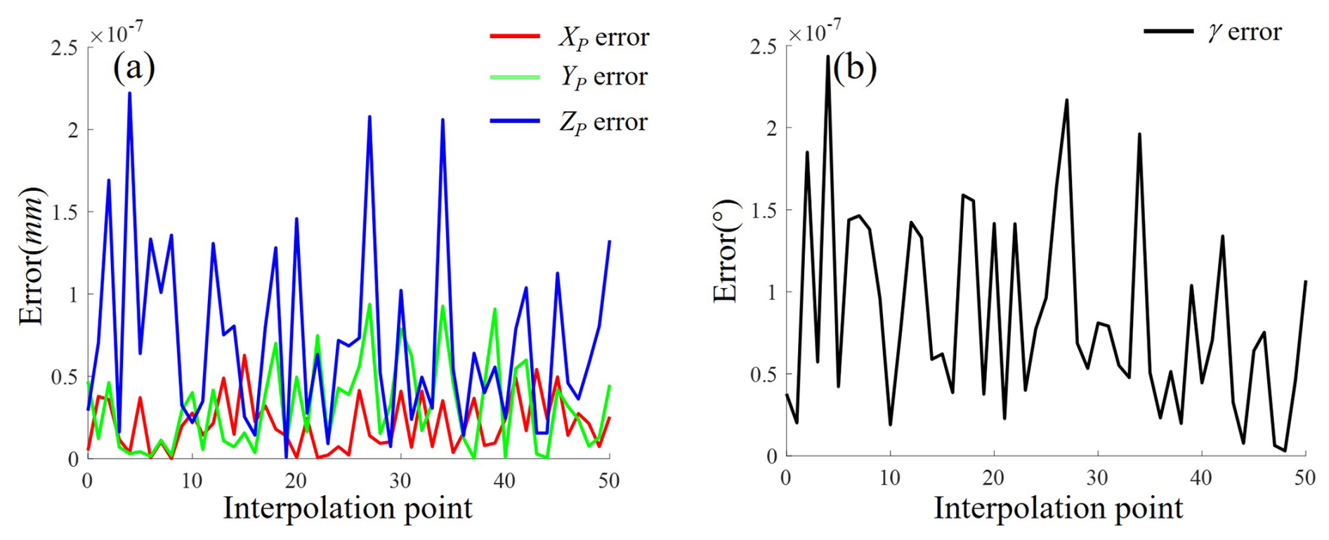
To calculate the error of the IBWO algorithm in solving the forward kinematics equation of the 4-PUU PM, the 51 end-effector output poses from Fig. 6a are substituted into Eq. (13) to obtain the corresponding input driving rod lengths hi. These are used as the mechanism scale parameters. The IBWO algorithm is then independently run five times to solve for the output poses. The difference between the output poses obtained by the IBWO algorithm and the theoretical parameters is considered the error of the IBWO algorithm. The specific calculation expression is as follows:
In the equation, ΔEr is the error generated by the IBWO algorithm in solving the forward kinematics equation of the PM, n is the number of independent runs of the IBWO algorithm, FIBWO is the output position of the PM obtained by the IBWO algorithm, and FT is the theoretical output pose of the PM.
Based on this, the average error curve of the IBWO algorithm in solving the forward kinematics equation of the 4-PUU PM is shown in Fig. 6.
As shown in Fig. 8a, when the IBWO algorithm is used to solve the forward kinematics equation for the continuous trajectory of the 4-PUU PM, the maximum error generated is approximately mm. However, in practical engineering applications, an error of 0.01 mm is sufficient to meet the requirements. In conclusion, the roots of the forward kinematics equation of the 4-PUU PM solved by the IBWO algorithm meet the practical requirements. To improve the accuracy of the IBWO algorithm, it is only necessary to increase the acceptable root accuracy facc in the algorithm to achieve higher-precision roots.
This paper presents a 4-PUU PM with 3T1R DOF, whose workspace is unaffected by the actuated joints. The mechanism's DOF characteristics are analyzed using screw theory. Based on the constraint of link lengths, the forward and inverse kinematics equations of the mechanism are derived. On this basis, the first and second time derivatives of the forward kinematics equations are obtained, yielding the velocity and acceleration equations of the mechanism. Given the scale parameters and actuator parameters of the mechanism, simulation experiments are conducted using both MATLAB and Adams software. The experimental results validate the correctness of the kinematic analysis of the 4-PUU PM. An IBWO is proposed to solve the forward kinematics equations of the 4-PUU PM, and comparative algorithm experiments are performed. The experimental results show that the IBWO algorithm outperforms other comparison algorithms. Finally, based on the forward kinematics solutions for the interpolation points of continuous trajectories, it is found that the IBWO algorithm meets the accuracy requirements for the mechanism's practical applications.
In the future, the IBWO algorithm will be used for the optimization of the scale parameters of the 4-PUU PM. Based on the optimization results, a prototype will be designed, and the IBWO algorithm will be applied to the prototype for kinematic trajectory planning of the mechanism.
No data sets were used in this paper. Readers interested in the MATLAB implementation of the IBWO algorithm may contact the corresponding author via email to request the source code.
KW: writing (original draft), idea, methodology, validation, and investigation. XZ: modeling, simulation, and data processing. AJ: experimental code debugging. JL: supervision and manuscript revision.
The contact author has declared that none of the authors has any competing interests.
Publisher's note: Copernicus Publications remains neutral with regard to jurisdictional claims made in the text, published maps, institutional affiliations, or any other geographical representation in this paper. While Copernicus Publications makes every effort to include appropriate place names, the final responsibility lies with the authors. Views expressed in the text are those of the authors and do not necessarily reflect the views of the publisher.
This paper was edited by Daniel Condurache and reviewed by Baoyu Wang and three anonymous referees.
Arora, S. and Anand, P.: Chaotic grasshopper optimization algorithm for global optimization, Neural Comput. Appl., 31, 4385–4405, https://doi.org/10.1007/s00521-018-3343-2, 2019.
Company, O., Marquet, F., and Pierrot, F.: A new high-speed 4-DOF parallel robot synthesis and modeling issues. IEEE Trans. Robot. Autom., 19, 411–420, https://doi.org/10.1109/TRA.2003.810232, 2003.
Ghalambaz, M., Yengejeh, R. J., and Davami, A. H. :Building energy optimization using Grey Wolf Optimizer (GWO), Case Studies in Thermal Engineering, 27, 101250, https://doi.org/10.1016/j.csite.2021.101250, 2021.
Herbadji, D., Derouiche, N., Belmeguenai, A., Herbadji, A., and Boumerdassi, S.: A Tweakable Image Encryption Algorithm Using an Improved Logistic Chaotic Map, Trait Signal, 36, 407–417, https://doi.org/10.18280/ts.360505, 2019.
Krut, S., Benoit, M., Ota, H., and Pierrot, F.: I4: A new parallel mechanism for SCARA motions/Proceedings of the IEEE International Conference on Robotics and Automation, 14–19 September 2003, Taiwan, China, New York: IEEE, 2003, 1875–1880, https:/doi.org/10.1109/ROBOT.2003.1241868, 2003.
Li, C., Wu, H., and Eskelinen, H.: Design and Multi-Objective Optimization of a Dexterous Mobile Parallel Mechanism for Fusion Reactor Vacuum Vessel Assembly, IEEE Access. 2021, 153796 –153810, https://doi.org/10.1109/ACCESS.2021.3127947, 2021.
Li, Y., Mei, J., Liu, S., and Huang, T.: Dynamic dimensional synthesis of a 4-DOF high-speed parallel manipulator, J. Mech. Eng., 50, 32–40, 2014.
Liu, C., Cao, G., and Qu, Y.: Safety analysis via forward kinematics of delta parallel robot using machine learning, Safety Sci., 117, 243–249, https://doi.org/10.1016/j.ssci.2019.04.013, 2019.
Lu, Z. H. and Zhang, J.: An Enhanced Dung Beetle Optimization Algorithm for Global Optimization, Curr. J. Appl. Sci. Technol., 42, 9–22, https://doi.org/10.9734/cjast/2023/v42i174133, 2023.
Nabat, V., de la O Rodriguez, M., Company, O., Krut, S., and Pierrot, F.: Par4: Very high speed parallel robot for pick-and-place. Proceedings of the IEEE/RSJ International Conference on Intelligent Robots and Systems, 2–6 August 2005, Alberta, New York, IEEE, 2005, 1202–1207, https://doi.org/10.1109/IROS.2005.1545143, 2005.
Salgado, O., Altuzarra, O., Petuya, V., and Hernández, A.: Synthesis and Design of a Novel 3T1R Fully-Parallel Manipulator, J. Mech. Des., 130, 042305, https://doi.org/10.1115/1.2839005, 2008.
Shi, K., Wang, Z., Yan, C., and Wang, Z.: Design and performance analysis of the 4UPS-RRR parallel ankle rehabilitation mechanism, Mech. Sci., 15, 417–430, https://doi.org/10.5194/ms-15-417-2024, 2024.
Staicu, S., Shao, Z., Zhang, Z., Tang, X., and Wang, L.: Kinematic analysis of the X4 translational–rotational parallel robot, Int. J. Adv. Robot. Syst., 15, 1–12, https://doi.org/10.1177/1729881418803849, 2018.
Wu, X., Wu, S., Wang, C., Luo, J., and Wang, Y.: Kinematics analysis of a novel hybrid manipulator for optomechanical modules assembly, Fusion Eng. Des., 202, 1–6, https://doi.org/10.1016/j.fusengdes.2024.114316, 2024.
Wen, S., Ji, A., Che, L., and Yang, Z.: Time-varying external archive differential evolution algorithm with applications to parallel mechanisms. Appl. Mathmat. Model., 114, 745–769, https://doi.org/10.1016/j.apm.2022.10.026, 2023.
Wen, S., Wu, S., Qi, Q., Wu, H., Yang, Y., Cheng, Y., and Ji, A.: Design and position analysis of 2PUU-2PSS parallel mechanism for auxiliary assembly in DEMO vacuum vessel, Fusion Eng. Des., 2007, 114645, https://doi.org/10.1016/j.fusengdes.2024.114645, 2024.
Xiang, T., Liao, X., and Wong, K. W.: An improved particle swarm optimization algorithm combined with piecewise linear chaotic map, Appl. Math. Comput., 190, 1637–1645, https://doi.org/10.1016/j.amc.2007.02.103, 2007.
Xie, F., Li, T., and Liu, X. Type synthesis of 4-DOF parallel kinematic mechanisms based on Grassmann line geometry and atlas method, Chin. J. Mech. Eng., 26, 10731081, https://doi.org/10.3901/cjme.2013.06.1073, 2013.
Yang, S., Sun, T., and Huang, T.: Type synthesis of parallel mechanisms having 3T1R motion with variable rotational axis, Mech. Mach. Theory., 109, 220–230, https://doi.org/10.1016/j.mechmachtheory.2016.11.005, 2017.
Zhong, C., Li, G., and Meng, Z. Beluga whale optimization: A novel nature-inspired metaheuristic algorithm, Knowl. Based Syst., 251, 109215, https://doi.org/10.1016/j.knosys.2022.109215, 2022.
Zhu, Z., Liu, Y., He, Y., Wu, W., Wang, H., Huang, C., and Ye, B.: Fuzzy PID Control of the Three-Degree-of-Freedom Parallel Mechanism Based on Genetic Algorithm, Appl. Sci., 12, 11128, https://doi.org/10.3390/app122111128, 2022.
- Abstract
- Introduction
- 4-PUU structural description and DOF analysis of PMs
- 4-PUU PM kinematic analysis
- Beluga whale optimization for forward kinematics analysis
- Numerical experiment verification
- Conclusions
- Code and data availability
- Author contributions
- Competing interests
- Disclaimer
- Review statement
- References