the Creative Commons Attribution 4.0 License.
the Creative Commons Attribution 4.0 License.
 | 29 Oct 2025
Error modelling and experimental validation for a new-type series-parallel stable platform
Xinlei Xiao
Da Song
Yanda Jiang
Bo Cui
Lixun Zhang
Feng Xue
To provide a highly stable reference plane for navigation and aiming systems on moving carriers, this paper presents a novel three-degrees-of-freedom (3-DoF) series-parallel stabilisation platform (SPSP). This platform effectively eliminates longitudinal and lateral carrier sway while dynamically adjusting azimuth angles for target tracking. We designed the SPSP configuration and analysed its kinematic degrees of freedom (DoF). Based on the mechanism's operating principles, factors influencing the moving platform's attitude error (AE) were systematically investigated, and an error model was established using partial differential methods. Simulation studies quantified the impact of individual error sources on AE, enabling rational error allocation. Critical factors affecting rod length error (RLE) were identified, leading to proposed methods for enhancing the accuracy of gear and lead screw transmissions. An experimental platform was constructed using a dSPACE hardware-in-the-loop simulation system. Validation experiments included electromechanical actuator precision tests, open-loop SPSP positioning tests, and closed-loop stability tests, confirming the error model's validity and configuration design rationality.
- Article
(7999 KB) - Full-text XML
- BibTeX
- EndNote


Vehicles, aircraft, and other transportation systems have garnered significant scholarly attention. Environmental perturbations induce vibrations and displacements in these carriers, whereas onboard navigation and aiming equipment requires real-time stability. Conventional stabilisation platforms are categorised as either serial or parallel architectures (Kuseyri, 2016; Zhou et al., 2025; Ding et al., 2025; Chen et al., 2016; Dong et al., 2022; Yang et al., 2022; Yue et al., 2010). To mitigate accuracy degradation caused by manufacturing errors and structural compliance in conventional platforms, we designed a novel series-parallel stabilisation platform (SPSP) configuration and conducted an in-depth analysis of error sources to enhance platform stiffness and motion accuracy.
Usually, the error and accuracy of a stable platform are inversely proportional. The larger the error, the lower the accuracy; the smaller the error, the higher the accuracy (Mei et al., 2021). To improve the accuracy of a stable platform, it is necessary to minimise the error to the greatest extent, and the error model becomes particularly important. There are currently three commonly used error modelling methods: the first is the matrix differentiation method, the second is the error influence coefficient method, and the third is the vector differentiation method (Li et al., 2025; Yao et al., 2013). The essence of both the matrix differentiation and error influence coefficient methods is to use the D-H method to establish error models for each branch chain. Masory et al. used the D-H method to establish error models for each branch chain on the Stewart platform and obtained the end error through numerical solution (Masory et al., 1996). The vector differential method establishes an error model by taking the differential of the kinematics equation of a parallel mechanism; e.g. Ropponen and Arai (1995) used this method to establish the error model for the Stewart platform and obtained the relationship between structural parameters, transmission components, and end errors (Song et al., 2024). Establishing an accurate error model requires in-depth analysis of the causes of stable platform errors.
The main sources of errors in stable platforms can be divided into four aspects: due to machining and assembly errors that create gaps between parts, moving parts may experience mechanical transmission errors during mechanical transmission; in the detection process, detection errors are introduced due to the inherent errors and accuracy limitations of the detection device; during the working process of the mechanism, deformation errors are introduced due to changes in external temperature and pressure and also due to sustained external and inertial forces that cause deformation of the mechanism components; finally, there are control errors in the control system, mainly caused by the selection of control algorithms and controller parameters (Liu et al., 2022a, b; Wen et al., 2023; Luo et al., 2021; Chong et al., 2021). This paper mainly considers manufacturing errors and mechanical transmission errors, providing a theoretical and technical basis for the control of stable platforms.
2.1 SPSP mechanism principle
Based on the motion analysis of the carrier during movement and the functional requirements of the stable platform, this paper proposes a novel three-degrees-of-freedom (3-DoF) SPSP. Its working principle is shown in Fig. 1, and the three degrees of freedom of the SPSP comprise pitch, roll, and azimuth. The pitch and roll degrees of freedom are designed based on a two-degrees-of-freedom (2-DoF) parallel mechanism with passive chains, used to eliminate longitudinal and lateral sway of the carrier. The azimuth motor and gear transmission complete the adjustment of the azimuth angle and have the function of adjusting the azimuth angle according to the different aiming targets of the platform load.
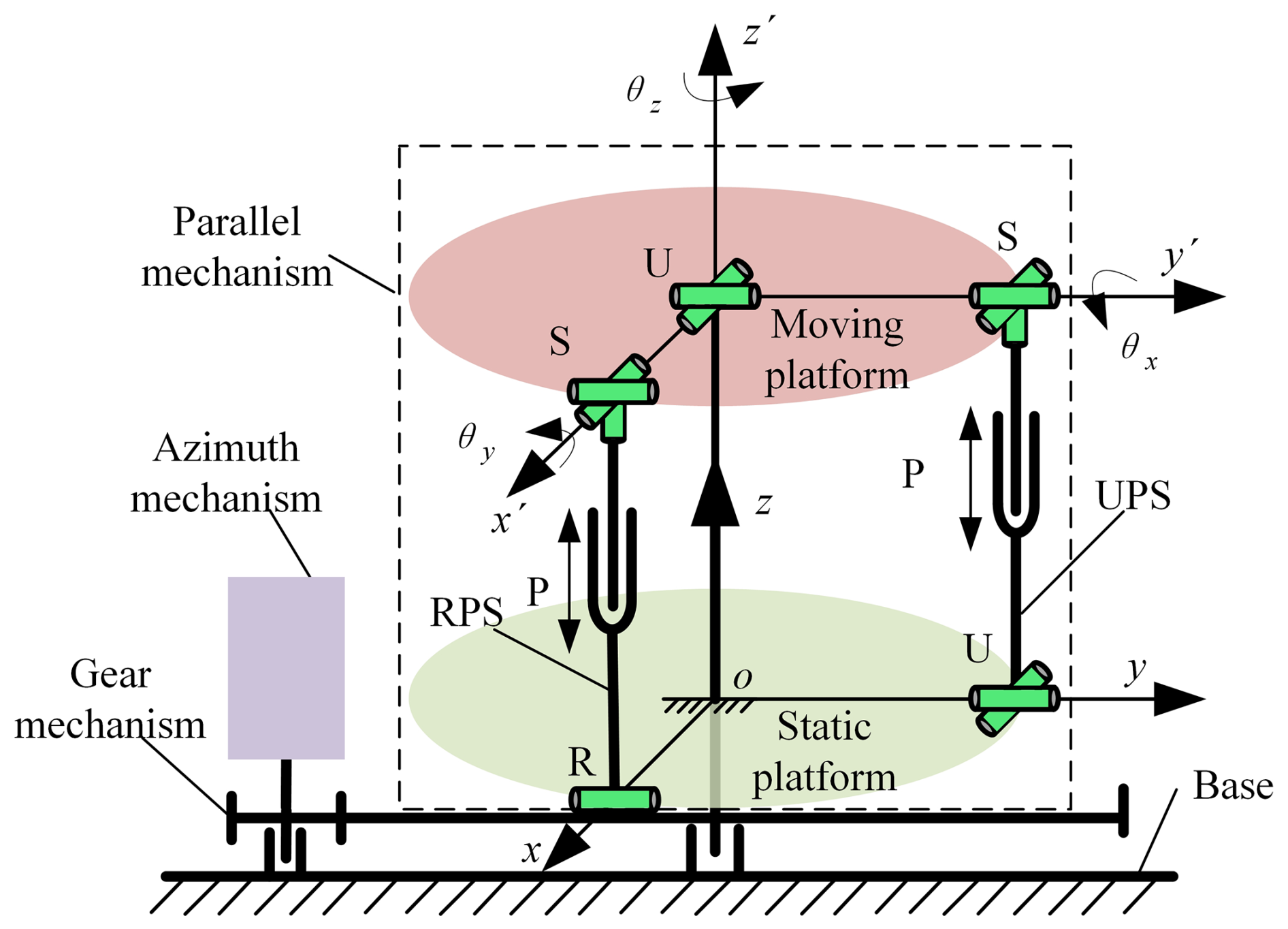
In Fig. 1, it can be seen that the 3-DoF SPSP is composed of a 2-DoF parallel platform and a directional mechanism connected in series.
2.2 Degree of freedom analysis of parallel mechanisms
The parallel mechanism designed based on U-RPS/UPS is shown in Fig. 1. The organisation consists of a moving platform, a static platform, a U branch, an RPS branch, and a UPS branch. Among them, the RPS branch and the UPS branch are orthogonal and equidistant, with the U branch located at the orthogonal centre. The moving platform is connected to the column fixed to the static platform through the U branch. In the RPS branch, the rotating pair (R) is connected to the static platform, the ball joint (S) is connected to the moving platform, and the axis of the moving pair (P) passes through the centre point of the ball joint (S) and coincides with the vertical axis of the rotating shaft. When the moving pair (P) moves up and down, it pushes the moving platform to rotate around the y axis of the U branch, achieving a change in the pitch angle θx of the moving platform.
In the UPS branch, the Hooke hinge (U) is connected to the static platform, and one of the rotating axes in the U hinge is parallel to the R axis of the rotating pair in the RPS branch. The ball joint (S) is connected to the moving platform, and the centre of the S joint is in the same horizontal plane as the centre of the S joint in the RPS branch. The axis of the moving pair (P) passes through the centre point of the ball joint (S) and coincides with the vertical axis of rotation. When the moving pair (P) moves up and down, it pushes the moving platform to rotate around the x axis of the U branch, achieving a change in roll angle θy.
Firstly, it is necessary to analyse the composition and characteristics of parallel mechanisms and to further analyse their degrees of freedom using screw theory. Due to the correlation between the spiral system and the selection of coordinate systems, in order to simplify the calculation, a coordinate system as shown in Fig. 2 is established. The dynamic coordinate system is established on the moving platform, and the static coordinate system O−xyz is established on the static platform. The origin of the moving coordinate system P is the centre of the Hooke hinge U branch, with the x′ axis collinear with PA1 and the y′ axis collinear with PA2. The origin O of the static coordinate system O−xyz is the projection of point P on a static platform, with the x axis collinear with OB1 and the y axis collinear with OB2.
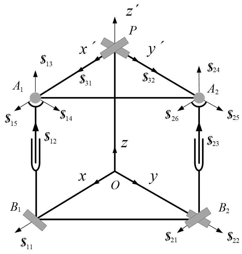
The centre of the ball joint connecting the RPS branch to the moving platform is A1, and the centre of the rotating pair R connecting to the static platform is B1. The centre of the ball joint connecting the UPS branch to the moving platform is A2, and the centre of the rotating pair R connecting to the static platform is B2. The centre of the Hooke hinge U branch is the origin of the moving coordinate system P.
The motion spiral system of the RPS branch at its initial position is
where .
Then, the counter-helix of Eq. (1) is
At the initial position, α=0, β=0, the anti-helix is , and the anti-helix is a force vector.
The motion spiral system of the UPS branch in its initial position is
Due to the rank of the matrix composed of six helices in the motion spiral system being 6, there is no anti-helix, meaning that the UPS branch does not have any constraints on the platform.
The motion spiral system of the U-branch is
Therefore, the total anti-spiral system is
In the anti-spiral system, represents the limit on the rotation of the moving platform around the Z axis, and , , and limit the movement of the moving platform along the three coordinate axes, respectively.
In summary, the constraint spiral system of the dynamic platform of the mechanism is
By finding the inverse helix of Eq. (6), the motion helix system of the moving platform can be obtained as
The moving platform is equivalent to being solely constrained by the Hooke hinge U, with only two degrees of freedom for rotational motion along the two axes of the Hooke hinge.
The motion spiral represents rotation around the x axis, and the motion spiral represents the rotational motion around the y axis.
2.3 Overall structure of SPSP
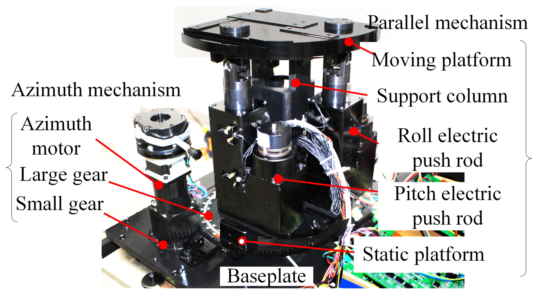
The prototype of the SPSP principle is shown in Fig. 3, which mainly includes two parts: a 2-DoF parallel platform and a directional mechanism connected in series with it. The 2-DoF parallel platform mainly consists of a dynamic platform, a static platform, an upper support column, a longitudinal electromechanical actuator, a transverse electromechanical actuator, and other components. The dynamic platform is installed on the upper support column through a Hooke hinge, and the longitudinal and transverse electromechanical actuators are orthogonally distributed below the dynamic platform and connected to it through the upper Hooke hinge components. The electromechanical actuator extends and pushes the dynamic platform to rotate around the two rotating axes of the Hooke hinge, and the static platform plays a role in supporting the vertical and horizontal electromechanical actuator and transmitting the rotational motion of the azimuth mechanism. The azimuth mechanism mainly includes an azimuth stepper motor, a large gear, a small gear, a left and right limit protection travel switch, and a zero-position photoelectric switch. The large gear is fixed together with the static platform, and the azimuth motor drives the 2-DoF parallel platform to rotate as a whole through the gear.
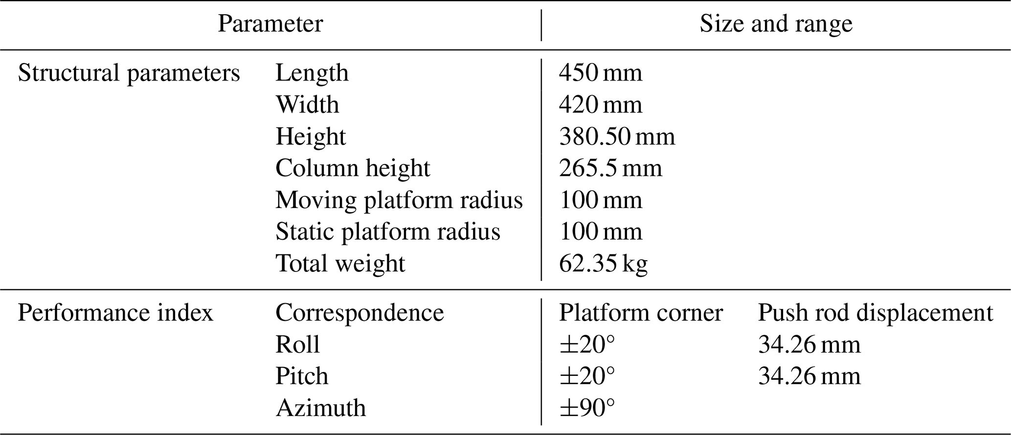
The main structural parameters of the SPSP are shown in Table 1.
3.1 Establishing error models by differential method
The key to establishing an error model is to find the source of SPSP errors. Through the error model, the impact of various error quantities on the end pose error of the moving platform can be studied, indicating the focus and direction for improving the accuracy of the end pose of the moving platform and providing a theoretical basis for structural parameter design. The main error sources of a 3-DoF SPSP include three aspects: the structural size parameter error, the rod length error (RLE), and the hinge and gear transmission clearance error. In this paper, a small amount of interference fit is used for all hinge axis hole fits, so the influence of the hinge clearance error on the system error can be ignored. The influence of the structural size parameter error and the RLE on the attitude error (AE) of the 2-DoF parallel mechanism platform is analysed emphatically. The structural dimension parameters include the distance error between the centre points of the two hinges of the moving platform and the centre of the moving platform, as well as the height error of the supporting column. The RLE includes the longitudinal electric push RLE and the transverse electric push RLE. The influencing factors that cause the RLE include gear clearance error and screw transmission clearance error. The errors in structural size parameters are mainly caused by machining and assembly errors. We analyse the impact of various error sources on the attitude angle error of the moving platform and clarify the focus and direction of improving the error sources.
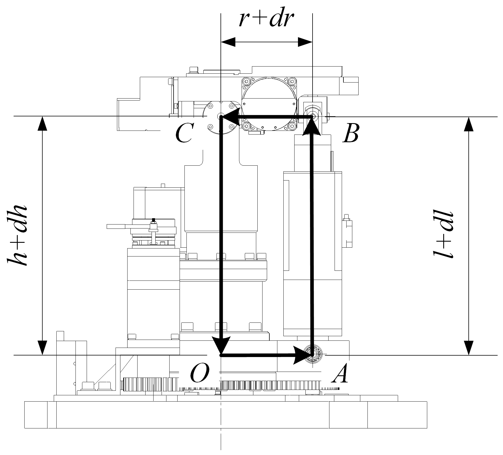
Figure 4 shows the initial position of the moving platform when it is in a horizontal state. There are four points (O, A, B, and C) in Fig. 4, representing the rotation centre of the static platform, the lower hinge point of the electromechanical actuator, the upper hinge point of the electromechanical actuator, and the centre of the moving platform. Due to the fact that the dynamic platform and the static platform are connected in the form of a Hooke hinge by supporting columns, the dynamic platform is limited to only two degrees of freedom to rotate around the Hooke hinge axis. The distance between them in Fig. 4 is the height of the supporting column and is the length of the structural parameter radius (SPR), which is the length of the rod. The following relationship applies at any time.
The roll electromechanical actuator and pitch electromechanical actuator work simultaneously, and the moving platform has two tilt angles θx and θy relative to the ground. By bringing the parameters into Eq. (8), the relationship between the parameters can be obtained as follows:
The detailed derivation process can be found in Appendix A.
The final AE model of a 2-DoF parallel mechanism can be obtained as
where
The above formula shows the relationship between the attitude angle errors dθx and dθy of the moving platform, the structural parameter errors dr and dh, and the rod length errors dl1 and dl2. When the structural parameters and their errors, the rod length errors, and the attitude angle of the moving platform are given, the required rod length can be calculated according to the inverse solution of kinematics, and the attitude angle error of the moving platform can be solved using the above formula.
3.2 Dynamic error analysis
Based on the above error model, combined with the given geometric parameters, initial position parameters, and error parameters of the mechanism, an example simulation is conducted using MATLAB. The studied errors can be set in sequence, with the remaining errors set to 0 for simulation, and the impact of each error on the attitude angle error of the moving platform can be studied. The impact of error sources can be analysed through two forms: one is to load error sources sequentially for dynamic error analysis based on the angle of continuous changes in system input; another method is to perform static error analysis by increasing the values of error sources in sequence, given a constant angle of system input.
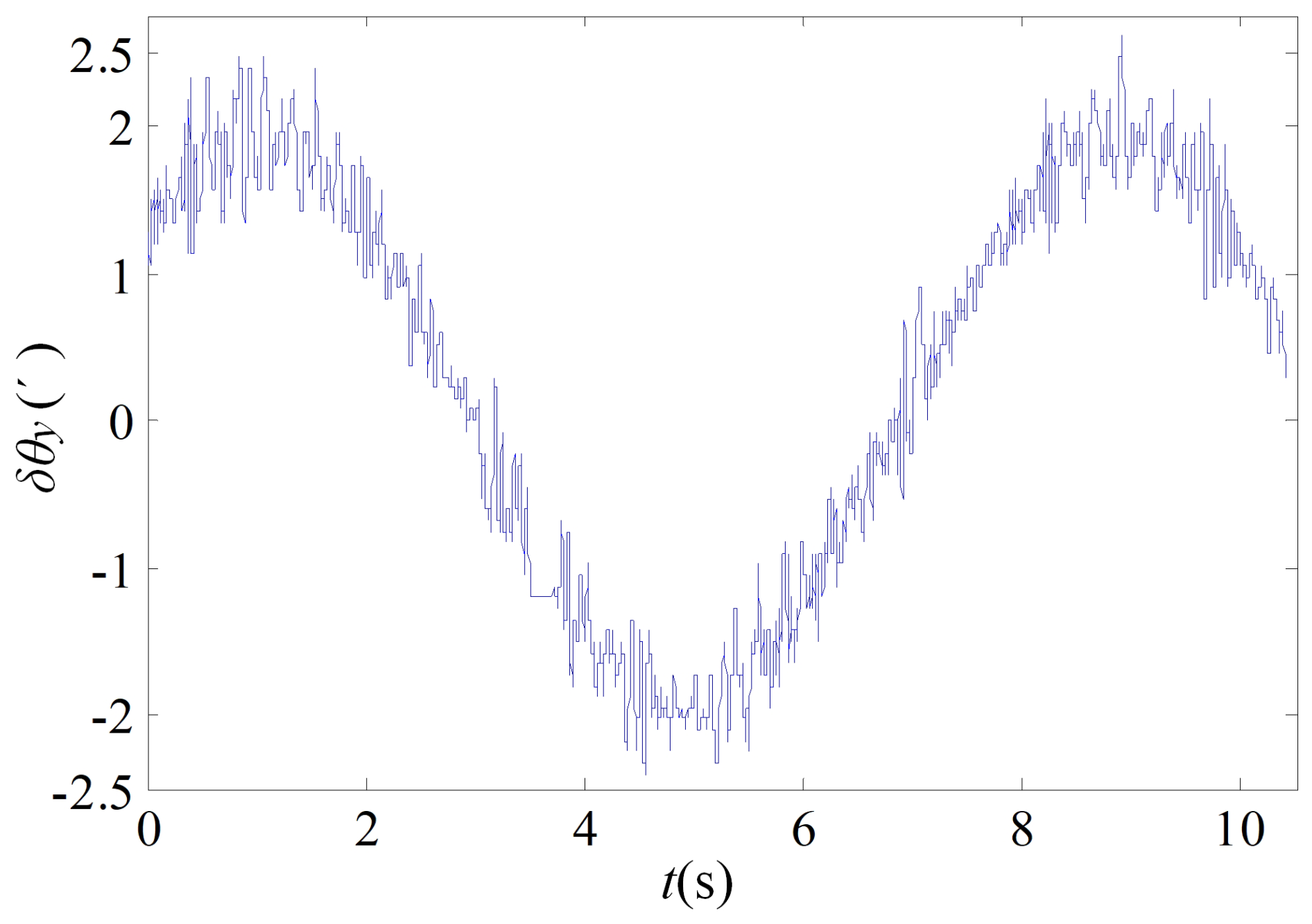
The first analysis method involves a sine signal with a pitch angle amplitude of 15° and a period of 4 s, along with a sine signal with a roll angle amplitude of 20° and a period of 8 s. The values of each error source are set in sequence as shown in Table 2, while the remaining error sources are 0.
Table 2Mechanism size and error parameters (unit: millimeters).
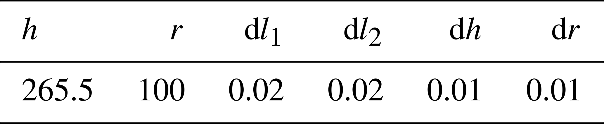
When there is an error in the length of the pitch electromechanical actuator, dl1=0.02 mm and all other errors are 0. By incorporating the parameters into the equation, the variation curve of the AE of the moving platform can be obtained as shown in Fig. 5a. When there is only a structural parameter error dl2=0.02 mm, all other errors are 0. Inputting the parameters into the model yields variations in the AE of the moving platform, as shown in Fig. 5b.
In Fig. 5a, it can be seen that, when there is only a pitch electric push RLE dl1=0.02 mm, there is not only a pitch angle error dθx, but also an error of dθy caused by dl1 on the roll angle; the maximum error caused by the roll angle is approximately , and the error caused by the pitch angle is . The reason why the curve is not symmetrical is that, given an error of , the absolute value of the maximum error at the peak of the curve is greater than the absolute value of the maximum error at the trough. When is set, the opposite result can be obtained; that is, the absolute value of the maximum error at the trough of the curve is greater than the absolute value of the maximum error at the peak. In Fig. 5b, it can be seen that only the length error dl2=0.02 mm of the roll electromechanical actuator has no effect on the pitch angle and that it only has an amplitude of about 0.9′ on the roll angle. In comparison with Fig. 5a, it can be seen that the length error dl2 of the roll electromechanical actuator has a relatively small impact on the angle error of the moving platform.
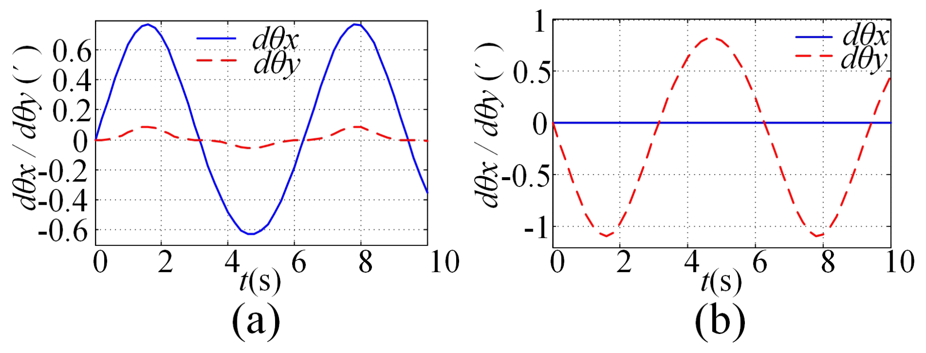
When there is a structural parameter error dr=0.01 mm, all other errors are 0. Inputting the parameters into the model yields variations in the AE of the moving platform, as shown in Fig. 6a; when there is only a structural parameter error dh=0.01 mm, all other errors are 0. Inputting the parameters into the model yields variations in the AE of the moving platform, as shown in Fig. 6b.
In Fig. 6a, it can be seen that, when there is only a structural parameter error dr=0.01 mm, it causes an error of more than 0.1′ for the roll angle and a relatively small error for the pitch angle; comparing Fig. 5a and b, it can be seen that the error of structural size parameter dr has a more significant impact on the attitude angle error of the moving platform. In Fig. 6b, it can be seen that, when there is only a structural parameter error dh=0.01 mm, it causes an error that fluctuates around 0.4′ for the roll angle. That is, when there is an error of dh=0.01 mm, there is always an error close to 0.4′ for the roll attitude of the moving platform, bringing a nearly symmetrical amplitude error of 0.2 to the pitch angle. In comparison with Fig. 5b, it can be seen that the error of structural size parameter dh has a relatively small impact on the attitude angle error of the moving platform.
When all error sources exist simultaneously, dl1=0.02 mm, dl2=0.02 mm, dr=0.01 mm, and dh=0.01 mm input the parameters into the model to obtain the AE of the moving platform, as shown in Fig. 7.
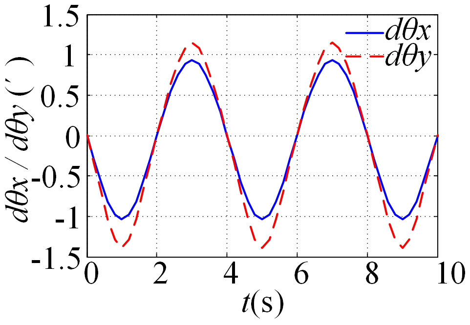
In Fig. 7, it can be seen that, when all error sources exist simultaneously, the impact of error sources on the roll attitude angle error of the moving platform is greater than that on the pitch attitude angle. Therefore, in practice, it is necessary to strictly control the error sources that affect the roll attitude angle.
3.3 Static error analysis
The second method is to give the system input a constant angle, load one error source at a time and increase the error value step by step, and study the impact of each error source on the attitude angle error of the moving platform.
The moving platform serves as reference points at four extreme positions, including the following four postures:
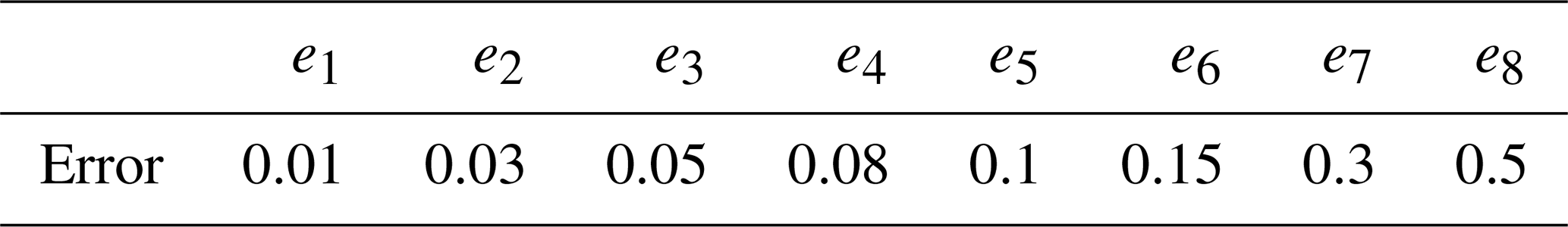
The values of each error source were set in sequence to the values in Table 3 and analysed separately for a single error source.
-
Attitude angle error of the moving platform at position point A and B.
The pose values of point AB in Eq. (12) and the nominal values of the error source in Table 3 were introduced into the error model, and the error results were obtained as shown in Fig. 8a–d.
-
Attitude angle error of the moving platform at position point C and D.
The pose values of point C in Eq. (12) and the nominal values of the error source in Table 3 were introduced into the error model, and the error results were obtained as shown in Fig. 9a–d.
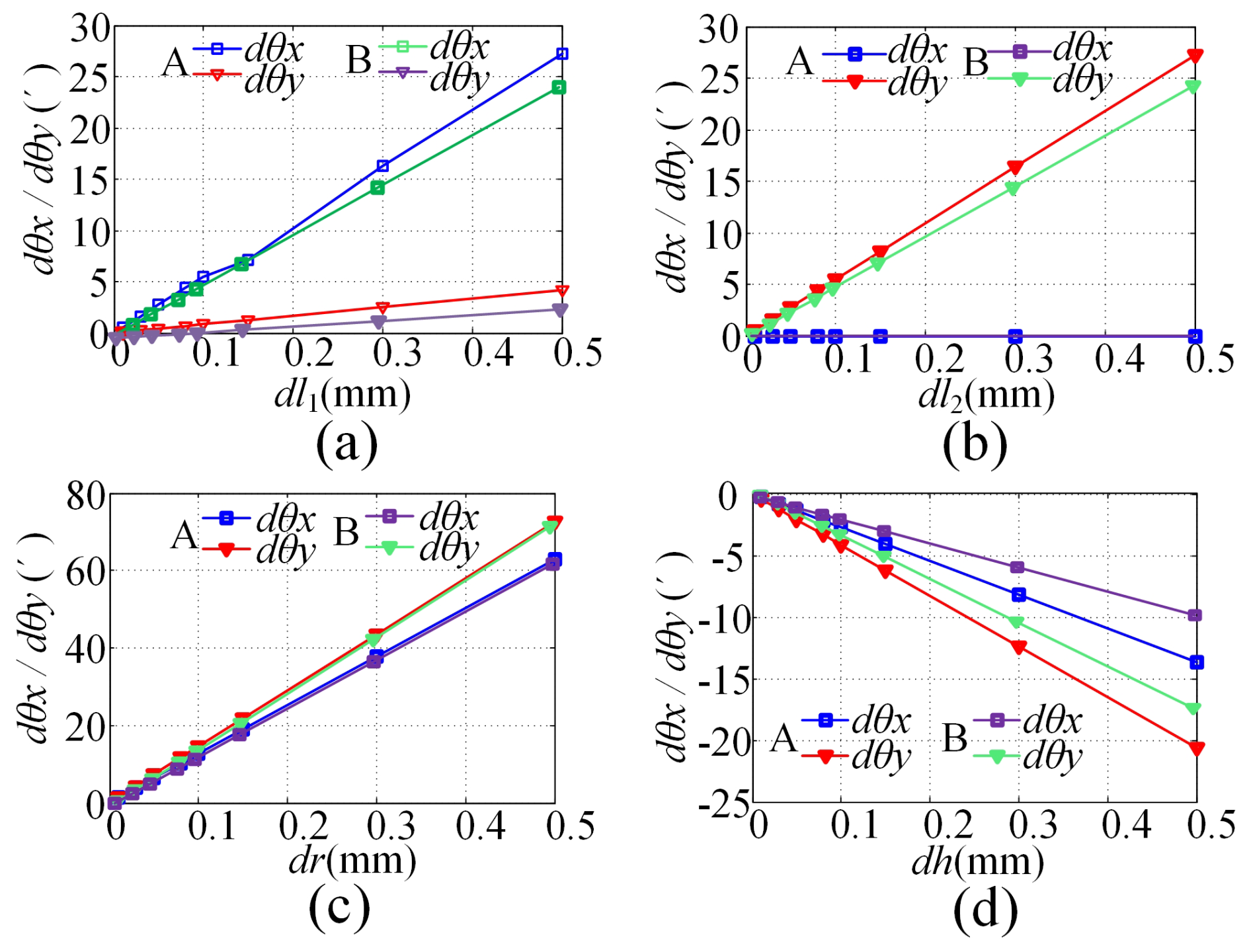
Figure 8Attitude angle error of the moving platform at position points A and B: (a) dl1, (b) dl2, (c) dr, (d) dh.
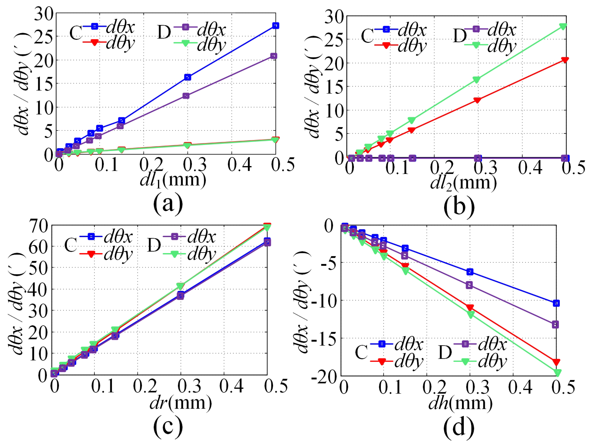
Figure 9Attitude angle error of the moving platform at position points C and D: (a) dl1, (b) dl2, (c) dr, (d) dh.
In Figs. 8 and 9, it can be seen that, under the influence of a single error source, the attitude angle error of the moving platform will vary linearly with the error source. In addition, among the four error sources analysed, the error that has the greatest impact on the attitude angle error of the moving platform is the SPR error, which has a much greater impact than the RLE and structural parameter height error. Therefore, in design and processing, it is necessary to prioritise ensuring the accuracy of the SPR; that is, the accuracy level of the radius should be the highest.
3.4 Error distribution
Given the expected total error at the end of the system, solving the errors in each link belongs to error allocation. Based on the functions of each link and the degree of impact of errors on system errors, the errors of each link were determined, and the error values of each link were brought into the error model to synthesise system errors for analysis. We checked whether the synthesised system errors met the design requirements; if not, we readjusted the error values of each part, synthesised the errors again, and repeated experiments until the synthesised system errors met the design requirements.
Through the above analysis, the values of each error source were obtained. Table 4 provides a reasonable set of error allocation values, and the error values are incorporated into the error model to obtain the comprehensive error as shown in Fig. 10.
In Fig. 10, it can be seen that the maximum comprehensive error does not exceed , indicating that the error distribution is reasonable and meets the design requirements.
3.5 Analysis of the causes of errors
RLE refers to the elongation error of the electromechanical actuator, which is mainly caused by the rod length manufacturing error, the gear transmission error, and the screw transmission error, as shown in Fig. 11.
The manufacturing error of the rod length is caused by the limitations of processing and manufacturing accuracy, and, due to the scalability of the electromechanical actuator in the structure, it will compensate for the manufacturing error of the rod length; the existence of gear and screw transmission errors can cause the feed rate of the push rod to lag relative to the command signal during each reverse direction, even losing the command pulse and generating a reverse dead zone, which seriously affects the overall transmission accuracy of the system (Zhou et al., 2021; Mablekos-Alexiou et al., 2021; Zhao et al., 2019).
3.5.1 Gear transmission accuracy
The impact of gear manufacturing errors on gears is mainly manifested in two aspects: normal backlash and tooth thickness limit deviation. Side clearance refers to the clearance between the meshing teeth in a pair of assembled gear pairs, which is the amount by which the width of the tooth groove on the pitch circle exceeds the thickness of the meshing teeth. The side clearance of gears is generally evaluated using the direction of side clearance Jbn or circumferential side clearance Jwt, and generally Jbn=Jwtcos α. Gears that mesh with each other must have some backlash, and it is necessary to ensure that non-working tooth surfaces do not come into contact with each other. The situation that occurs in the design is that the side clearance of the designed or processed gears is too large, resulting in excessive clearance between the non-working tooth surfaces of the meshing gears. When the teeth rotate in the opposite direction, there will be idling. To avoid such problems, it is necessary to strictly control the side clearance of the gears.
Therefore, the following improvement measures should be taken in the design of gears:
-
Double-sided gears (with elastic torque between the two plates) should be used to maintain a seamless meshing state of the shaft system.
-
During assembly, optional gears should be used, or the centre distance should be adjusted, to maintain small backlash and friction in the gear train.
-
The manufacturing accuracy of the final-level gear and the assembly accuracy of the shaft should be improved.
-
Belt transmission or bevel gear transmission methods should be used to reduce spur gear transmission.
3.5.2 Screw transmission accuracy
The screw pair of the screw nut is a common main transmission component for linear motion, which can convert rotational motion into linear motion. The motion accuracy and positioning accuracy of the electromechanical actuator are directly related to the motion accuracy of the screw pair. The main factors that affect the motion accuracy of the screw pair are the pitch accuracy, pitch accumulation accuracy, and installation accuracy of the lead screw. At the same time, there are also other factors, such as the combined effect of the screw pair fitting accuracy and clearance friction or thermal deformation (Lin et al., 2017; Zhen and An, 2017; Zou et al., 2021). This article analyses the main factors that affect transmission accuracy in the following three aspects: pitch manufacturing accuracy, screw pair design clearance, and thermal deformation influence. The purpose of analysing errors is to find out the error relationship, and, using compensation control formulas, the goal of eliminating or reducing errors can be achieved.
The aspect ratio of lead screws is generally large, so the thermal deformation discussed in this article refers to the impact of changes in axial size after heating on transmission accuracy. The temperature change is ΔT, and the lead screw deformation is
where δyr is the deformation of the lead screw after heating, l0 is the total length of the lead screw, and a is the coefficient of thermal expansion of the lead screw.
In practical use, Eq. (13) can be used to achieve temperature compensation control, thereby eliminating or reducing the impact of SPSP temperature changes on the manufacturing accuracy of the screw.
4.1 Control system
The control system of the prototype experiment system of a 3-DoF SPSP is controlled by the upper and lower levels. The upper-level computer is composed of an industrial control computer and a dSPACE semi-physical simulation system, which can complete the input and output of control parameters, data collection, and storage and display; receive the return signal from the lower-level sensor; and send motor drive instructions to the lower-level computer. The lower computer is mainly composed of features such as an ARM controller, a motor drive module, and a signal processing module. It mainly completes the collection and conversion of instructions sent by the upper computer and sensor signals, such as the rotary transformer and inertial unit. The drive module sends corresponding drive signals based on the calculation results to achieve motor control.
The inertial unit feeds the attitude angle signal of the moving platform back to the upper computer through the A/D interface, and the switching value of the proximity switch is fed back to the upper computer through the I/O interface. Based on the angle information fed back by the inertial unit and the triggering information of the proximity switch, closed-loop control of the motor position can be completed, achieving precise reaching of the angle set by the upper computer or maintaining a fixed angle relative to the ground. The rotary transformer feeds the speed and position signals of the motor back to the upper computer through the A/D interface. Based on the rotational speed signal of the rotary transformer, the closed-loop control of the motor speed can be achieved, achieving smooth operation of the electromechanical actuator. The left and right travel switches of the directional mechanism and the middle photoelectric switch are fed back to the upper computer through the I/O interface. The upper computer can know the current position of the platform based on the trigger signals of the travel switch and the photoelectric switch. The overall structure of the control system is shown in Fig. 12.
4.2 Electric pusher precision testing experiment
The experimental system for precision testing of electromechanical actuators is shown in Fig. 13, mainly composed of electromechanical actuators, pulleys, weights, and grating rulers.
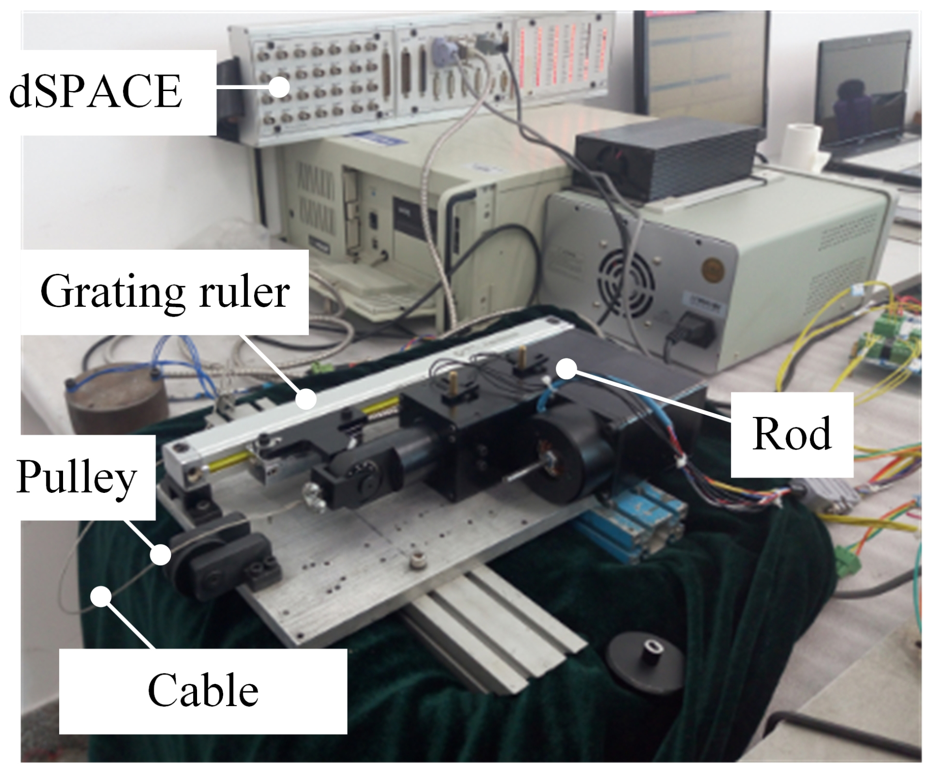
The accuracy of the SPSP rotary transformer can reach , with an excitation voltage of 7 V and an excitation frequency of 10 kHz. The grating ruler has a precision of 5 µm and a resolution of 1 µm. Under the conditions of manually adjusting the displacement of the push rod, the rotating transformer is powered on. The reading of the rotating transformer is collected by the lower computer, and the theoretical displacement of the push rod can be calculated through the transmission ratio. The grating ruler is connected to dSPACE, and the upper computer directly collects the reading of the grating ruler. The grating ruler and the push rod are fixed together, so the reading of the grating ruler is the actual displacement of the push rod. The difference between the reading of the rotary transformer and the reading of the grating ruler is the positioning accuracy of the electromechanical actuator. By changing the weight of the heavy object in sequence and repeating the above experiment, the positioning accuracy of the electromechanical actuator in the three states shown in Fig. 14 can be obtained.
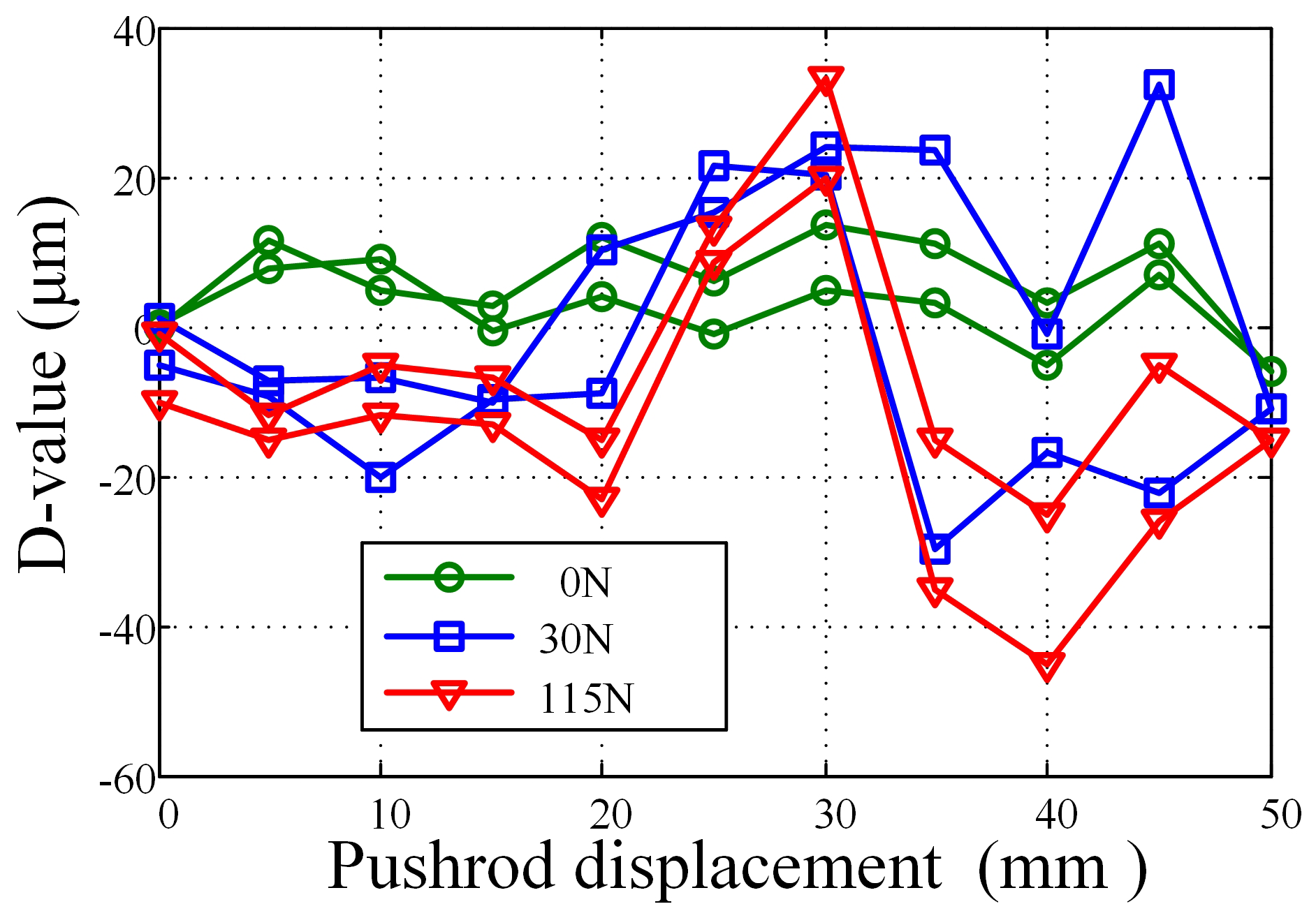
In Fig. 14, it can be seen that the curve moves downwards along the longitudinal axis as the load increases. The analysis reason is that, the larger the mass, the greater the force on the push rod and the poorer the accuracy of the electromechanical actuator mechanism. We also noticed that the curve decreases downwards as the displacement of the push rod increases. The reason for this analysis is that there is a deviation in the mechanism, specifically the parallelism deviation between the linear guide rail and the axis of the push rod movement. When loading 115N, the maximum positioning error of the electromechanical actuator shall not exceed 50 µm. Therefore, within the effective stroke of the electromechanical actuator, the repeated positioning error meets the design requirement of ±70 µm.
4.3 SPSP precision testing experiment
4.3.1 Open-loop positioning accuracy testing experiment
The open-loop state experiment can be used to detect the accuracy of platform mechanisms. The open-loop accuracy testing experiment can be divided into two steps, namely the open-loop static accuracy testing experiment and the open-loop dynamic accuracy testing experiment. The former refers to the non-continuous operation experiment of the moving platform in the open-loop state of the system, while the latter refers to the continuous operation experiment of the moving platform in the open-loop state of the system. It should be noted that static experiments are not loaded and that dynamic accuracy testing experiments are loaded. The experimental environment is shown in Fig. 14. The angle measuring element used is an inertial unit with a resolution of 0.1′ and an accuracy of 0.5′. It is directly calibrated using a 20-bit high-precision rotary transformer.
Firstly, the static positioning accuracy of the platform mechanism was tested in an open-loop state of the system. In the open-loop state, the platform angles were sequentially given, starting from −16° and increasing by 2° to 16° each time and then operating by decreasing by 2° each time until the end of −16°. Readings of the rotary transformer and inertial unit were taken after each given platform angle θ, and the readings were converted to platform end angle error δθ and screw end displacement error Δl through forward and inverse kinematics, as shown in Fig. 15.
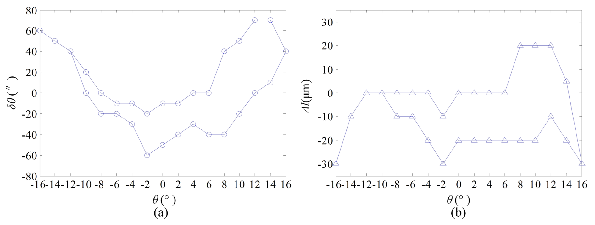
In Fig. 15a, it can be seen that, under loading, the platform angle changes from −16 to 16° and then from 16 to −16°. The maximum positioning error of the platform does not exceed 70′′, which is approximately 1.16′; the maximum error converted to the displacement of the electromechanical actuator and lead screw does not exceed 30 µm (approximately 1.15′). Therefore, it can be considered that the positioning accuracy of the platform mechanism reaches 1.16′, meeting the design requirement of mechanism accuracy of 5′. In Fig. 15b, it can also be seen that the mechanism has high repeatability in positioning accuracy, with close errors at the same position, indicating that the mechanism has strong repeatability.
Secondly, the dynamic positioning accuracy of the continuous operation of the platform was tested under the open-loop condition. A 7 kg simulated load was loaded onto the moving platform, and the angle change of the moving platform was given as a sine signal with an amplitude of 8° and a period of 8 s. The readings of the inertial unit and the rotating transformer were detected and recorded, and the data results were converted into platform end angle information and lead screw end displacement information through forward and inverse kinematics. The difference between the results was plotted to convert to the platform end angle error as shown in Fig. 16a and to convert to the lead screw displacement error as shown in Fig. 16b.
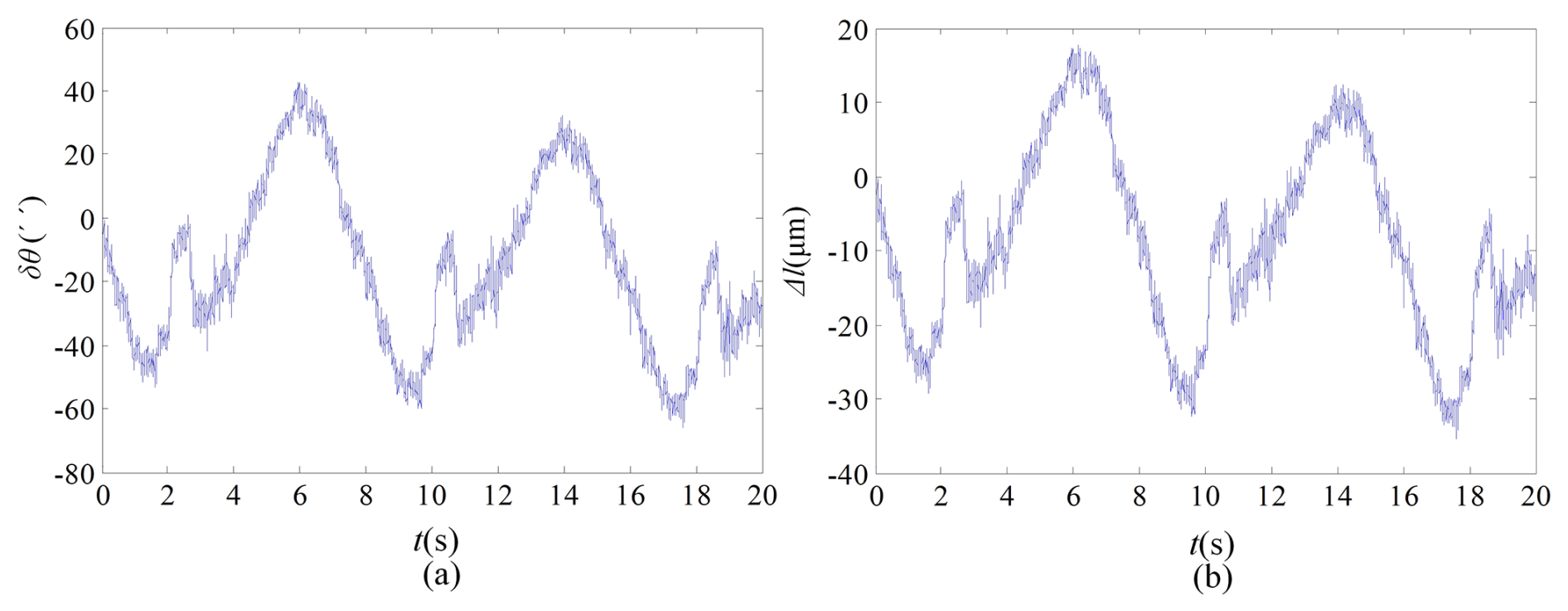
Analysing Fig. 16a and b, it can be seen that the maximum error of the platform does not exceed 50 s and that the maximum displacement error of the lead screw does not exceed 30 µm. The error range fully meets the positioning accuracy requirements. The reason for the asymmetry of the curve is that the bottom plate is placed in a horizontal plane, resulting in the deviation of the zero position of the electromechanical actuator and the zero position of the moving platform, resulting in the phenomenon of curve asymmetry. Note that the curve is not a smooth sine waveform, and there is a small wave peak in each cycle. The reason is analysed to be caused by the gaps in the mechanism when the moving platform is reversing, mainly in gear clearance, screw clearance, bearing clearance, and shaft hole fit clearance. It can also be seen that the size of these gaps is the value of each small wave peak.
Compared with Figs. 15a and 16a, it can be found that the static positioning accuracy is greater than the dynamic positioning accuracy. The reason is that, in the static experiment, each time when the platform angle is given, a PWM pulse is suddenly given to the motor, which makes the motor suddenly accelerate to the maximum speed and then rapidly reduce to zero. In this process, a great impact will be generated, which will bring great impact and vibration to the motor, lead screw, and platform. The result is that the gears and screws will have a return stroke each time and the readings of the inertial unit and rotary transformer will also undergo slight changes, ultimately resulting in an overall measurement accuracy that is much higher than the dynamic accuracy. Therefore, it is necessary to slowly set the platform angle without any impact while ensuring that the system operates in a vibration-free and temperature-appropriate environment.
In fact, static accuracy is mainly related to the machining accuracy and transmission accuracy of the parts, while dynamic accuracy is not only related to static accuracy, but also to the stiffness, vibration characteristics, and thermal deformation ability of the parts. So, in order to further improve the dynamic accuracy of the SPSP, it is necessary to improve the part process to improve the machining accuracy and transmission accuracy of the parts while also improving the part structure and selecting more suitable materials to improve the stiffness and resistance to thermal deformation of the parts, thereby improving the dynamic accuracy.
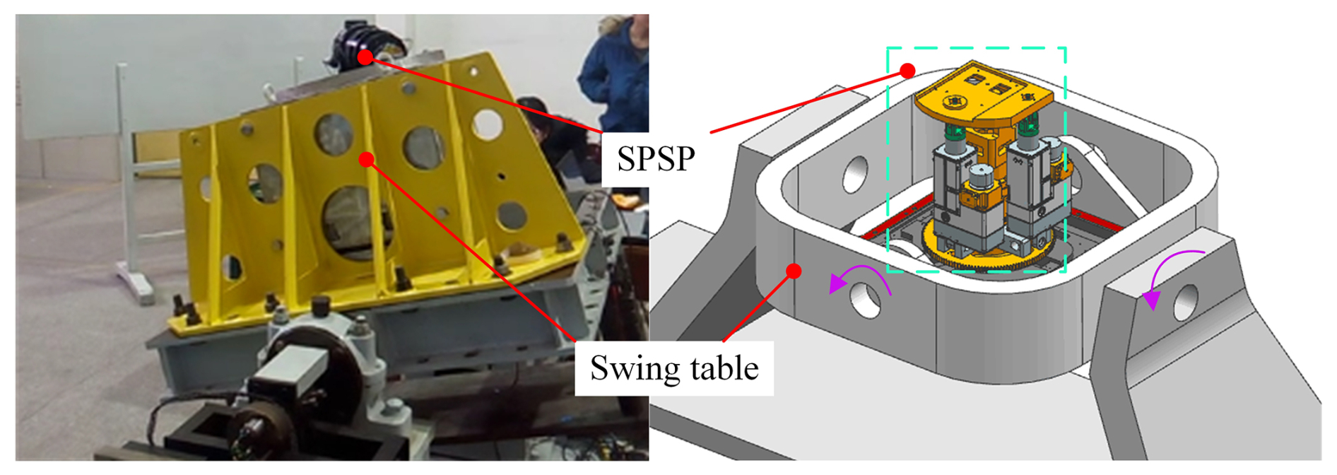
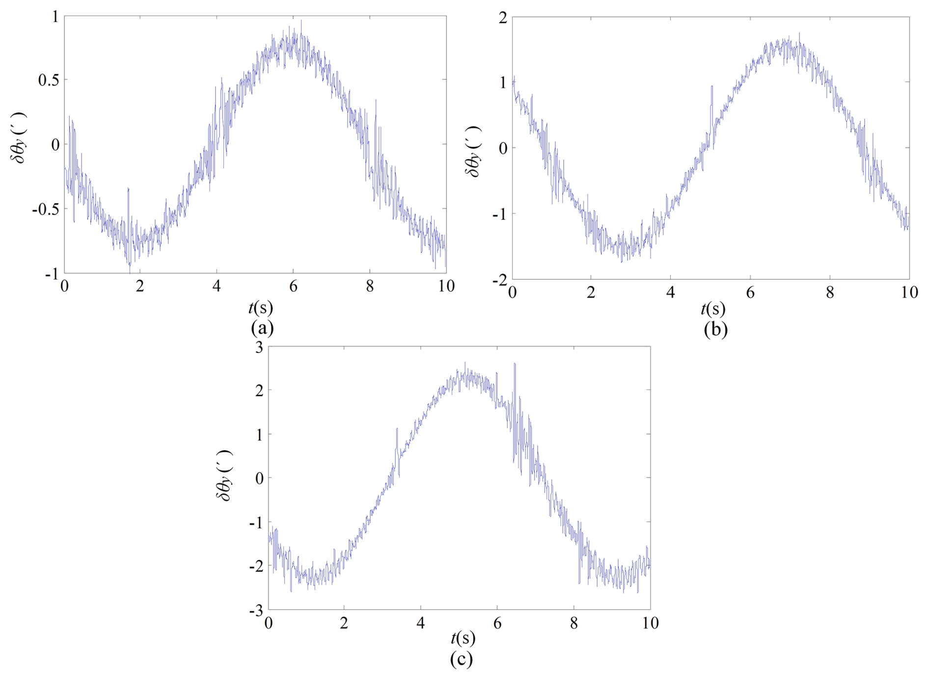
Figure 18Stability error when the amplitude of the swing table is 5°–15°: (a) 5°, (b) 10°, (c) 15°.
4.3.2 Closed-loop stability accuracy testing experiment
The closed-loop accuracy testing experiment refers to the overall stable accuracy that can be achieved by testing the SPSP when the bottom plate is in motion and is also the comprehensive control accuracy of the system. The experimental platform was installed on a 2-DoF swing platform to simulate the movement of the carrier for testing, as shown in Fig. 17. The accuracy of the continuous operation of the moving platform was tested in the position closed-loop state, and the inertial unit signal was sent as the feedback value to the upper computer. The position closed-loop control was achieved through controller compensation calculation. Simultaneously using the rotary transformer reading as feedback can achieve closed-loop control of the motor's speed, making the motor run more smoothly. The closed-loop experiment can be divided into two types: a single-degree-of-freedom swing experiment and a dual-degree-of-freedom swing comprehensive experiment.
-
Single-degree-of-freedom swing experiment.
Firstly, a single degree of freedom swing experiment is conducted, and this article takes the rolling electromechanical actuator as an example for analysis. Sine signals with roll angle rotation amplitudes of 5°, 10°, and 15° and a period of 8 s and provided for the swing platform. The inertial unit data at the end of the swing platform are used as the final angle error value.
When the rotation amplitude of the swing table is 5°, 10°, and 15°, the platform stability error is shown in Fig. 18.
In Fig. 18a–c, it can be seen that, as the rotation amplitude of the swing table increases, the error of the SPSP also increases and the stability accuracy decreases. The reason is that the angular velocity and angular acceleration of the platform will also increase with the increase in the rotation amplitude of the rocking table in the same period, and the inertial force of the platform will increase significantly, making the mechanism error, control error, etc. larger and ultimately reducing the stability accuracy of the platform. However, in the graph, it can be seen that, even if the error increases with the amplitude, the maximum error value is still less than 3′, indicating that the mechanism still maintains relatively high accuracy at 15°.
-
Comprehensive experiment of two-degrees-of-freedom swing.
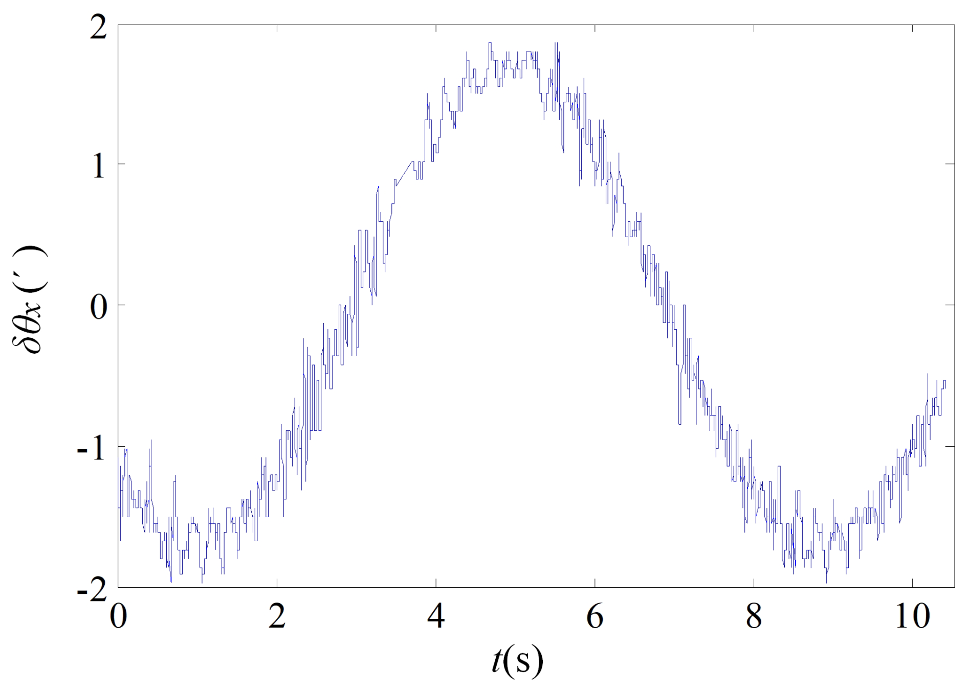
The pitch input command of the swing table is set as a sine command signal, with an amplitude of ±6° and a period of 4 s; the roll input command is also a sine command signal, with an amplitude of ±15° and a period of 8 s. The swing table is simultaneously horizontally and vertically rotated, the SPSP is installed on the swing table, and the pitch stability accuracy and roll stability accuracy are tested separately.
The control error signal of the pitch platform is tested, the peak range is identified, and the maximum dynamic tracking error is obtained. The measurement is repeated multiple times at different pitch angles, and the maximum value is used as the pitch dynamic error. The variation range of the pitch inertial unit data is shown in Fig. 19.
The control error signal of the rolling platform is tested, the peak range is identified, and the maximum dynamic tracking error is obtained. The measurement multiple times at different pitch angles is repeated, and the maximum value is used as the roll dynamic error. The changes in roll inertia unit data are shown in Fig. 20.
In Figs. 19 and 20, it can be seen that the pitch dynamic stability accuracy and roll dynamic stability accuracy are both within 3′, achieving the design requirement of 5′ for dynamic stability accuracy and verifying the rationality of the principle prototype design.
-
This article designs a 3-DoF SPSP, analyses the platform's degrees of freedom, establishes an error model, and analyses the degree to which each error affects the AE of the moving platform when inputting a sine signal, as well as the degree to which each error source affects the AE of the moving platform at a certain attitude.
-
It has been proven that the AE of the moving platform is most sensitive to the variation in SPR error. Through analysis, the error is allocated: when the length error of the longitudinal and transverse rocker rods is 70 µm, the height error of structural parameters is 50 µm. When the radius error of the structural parameters is 10 µm, the design requirements for the overall attitude angle error within 3′ are met.
-
The sources of rod length errors were analysed, and solutions to improve the accuracy of platform gear transmission and screw transmission were proposed.
-
An SPSP experimental system was built using the dSPACE semi-physical simulation platform, which verified the effectiveness of mechanism design and the accuracy of structural parameter design. The 3-DoF SPSP can achieve high-precision stability and azimuth adjustment of aiming equipment relative to the ground on a carrier tool with both pitch and roll swing.
The above equation can be written as
The formula includes key parameters that affect the AE of the moving platform, such as the length of the longitudinal electromechanical actuator l1, the length of the transverse electromechanical actuator l2, the distance r from the hinge point to the centre point of the moving platform, and the height of the support column h.
A partial differentiation was obtained for the equation
and further organised as
where
All the data used in this paper can be obtained by request from the corresponding author.
The authors' contributions are as follows: XX was in charge of the whole trial; DS, YJ, and BC wrote the article; and FX and LZ assisted with sampling and laboratory analyses. All authors read and approved the final article.
The contact author has declared that none of the authors has any competing interests.
Publisher's note: Copernicus Publications remains neutral with regard to jurisdictional claims made in the text, published maps, institutional affiliations, or any other geographical representation in this paper. While Copernicus Publications makes every effort to include appropriate place names, the final responsibility lies with the authors.
The authors thank the editors and reviewers for their efforts.
This research has been supported by the National Natural Science Foundation of China (grant no. 61773007).
This paper was edited by Zi Bin and reviewed by Baoyu Wang and two anonymous referees.
Chen, C., Liu, Z., Zhang, Y., Chen, C., and Xie, S.: Actuator backlash compensation and accurate parameter estimation for active vibration isolation system, IEEE Transactions on Industrial Electronics, 63, 1643–1654, https://doi.org/10.1109/tie.2015.2497664, 2016.
Chong, Z. H., Xie, F. G., Liu, X. J., and Wang, J.: Evaluation of dynamic isotropy and coupling acceleration capacity for a parallel manipulator with mixed DoFs, Mechanism and Machine Theory, 163, 104382, https://doi.org/10.1016/j.mechmachtheory.2021.104382, 2021.
Ding, J. Z., Zhou, Y. M., and Wang, C. J.: A geometric and analytical approach for the error modeling of a pointing parallel mechanism. Journal of Mechanisms and Robotics, Transactions of the ASME, https://doi.org/10.1115/1.4068799, 2025.
Dong, K. J., Li, D., Xue, X., Xu, C., Wang, H., and Gao, X.: Workspace and accuracy analysis on a novel 6-ucu bone-attached parallel manipulator, Chinese Journal of Mechanical Engineering, 35, 35, https://doi.org/10.1186/s10033-022-00689-1,2022.
Kuseyri, S.: Modelling and stabilization of a three-axis ship-mounted mobile antenna system. Proceedings of the Institution of Mechanical Engineers, Part M: Journal of Engineering for the Maritime Environment, 231, 1–9, https://doi.org/10.1177/1475090216661908, 2016.
Li, H., Chen, W., Yi, L., Leng, C., and Wu, H.: Design, modeling and manufacture error identification of a new 6-degree-of-freedom (6-DOF) compliant parallel manipulator, Mech. Sci., 16, 143–156, https://doi.org/10.5194/ms-16-143-2025, 2025.
Lin, B., Okwudire, C. E., and Wou, J. S.: Low order static load distribution model for ball screw mechanisms including effects of lateral deformation and geometric errors, Journal of Mechanical Design, 140, 022301, https://doi.org/10.1115/1.4038071, 2017.
Liu, J. M., Chen, Z. J., and Gao, F.: Kinematic calibration of a six-legged walking machine tool, Chinese Journal of Mechanical Engineering, 35, 34, https://doi.org/10.1186/s10033-022-00688-2, 2022a.
Liu, W., Du, J., Li, J., and Li, Z.: Stabilization control of 3-DOF parallel vessel-borne platform with dynamic uncertainties and unknown disturbances, Appl. Ocean Res., 126, https://doi.org/10.1016/j.apor.2022.103271, 2022b.
Luo, X., Xie, F. G., Liu, X. J., and Xie, Z.: Kinematic calibration of a 5-axis parallel machining robot based on dimensionless error mapping matrix, Robotics and Computer-Integrated Manufacturing, 70, 102115, https://doi.org/10.1016/j.rcim.2021.102115, 2021.
Mablekos-Alexiou, A., Cruz, L. D., and Bergeles, C.: Friction-Inclusive Modeling of Sliding Contact Transmission Systems in Robotics, IEEE Transactions on Robotics, 37, 1252–1267, https://doi.org/10.1109/TRO.2020.3045643, 2021.
Masory, O., Wang, J., and Zhuang, H.: Kinematic Modeling and Calibration for a Stewart Platform, Advanced Robotics, 11, 519–539, https://doi.org/10.1163/156855397X00191, 1996.
Mei, B., Xie, F. G., Liu, X. J., and Yang, C.: Elasto-geometrical error modeling and compensation of a five-axis parallel machining robot, Precision Engineering, 69, 48–61, https://doi.org/10.1016/j.precisioneng.2021.01.007, 2021.
Ropponen, T. and Arai, T.: Accuracy analysis of a modified Stewart platform manipulator, in: IEEE International Conference on Robotics and Automation (ICRA), 21–27 May 1995, Nagoya, Japan, 521–525, https://doi.org/10.1109/ROBOT.1995.525336, 1995.
Song, D., Xiao, X., Ma, J., and Zhang, L.: Modeling and control system experiment of a novel series three-axis stable platform, Mech. Sci., 15, 209–221, https://doi.org/10.5194/ms-15-209-2024, 2024.
Wen, J., Xie, F. G., Liu, X. J., and Yue, Y.: Evolution and development trend prospect of metal milling equipment, Chinese Journal of Mechanical Engineering, 36, 33, https://doi.org/10.1186/s10033-023-00865-x, 2023.
Yang, C., Ye, W., and Li, Q.: Review of the performance optimization of parallel manipulators, Mechanism and Machine Theory, 170, 104725, https://doi.org/10.1016/j.mechmachtheory.2009.12.006, 2022.
Yao, R., Zhu, W., and Huang, P.: Accuracy analysis of stewart platform based on interval analysis method, Chinese Journal of Mechanical Engineering, 26, 29–34, https://doi.org/10.3901/CJME.2013.01.029, 2013.
Yue, Y., Gao, F. Zhao, X., and Ge, Q. J.: Relationship among input-force, payload, stiffness and displacement of a 3-DOF perpendicular parallel micro-manipulator, Mechanism and Machine Theory, 45, 756–771, https://doi.org/10.1016/j.mechmachtheory.2009.12.006, 2010.
Zhao, J. J., Lin, M. X., Song, X. C., and Guo, Q. Z.: Investigation of load distribution and deformations for ball screws with the effects of turning torque and geometric errors, Mechanism and Machine Theory, 141, 95–116, https://doi.org/10.1016/j.mechmachtheory.2019.07.006, 2019.
Zhen, N. and An, Q.: Analysis of stress and fatigue life of ball screw with considering the dimension errors of balls, International Journal of Mechanical Sciences, 137, 68–76, https://doi.org/10.1016/j.ijmecsci.2017.12.038, 2017.
Zhou, C. G., Xie, J. L., and Feng, H. T.: Investigation of the decompression condition of double-nut ball screws considering the influence of the geometry error and additional elastic unit, Mechanism and Machine Theory, 156, 104164, https://doi.org/10.1016/j.mechmachtheory.2020.104164, 2021.
Zhou, Z., Qu, H., Li, X., Hu, B., and Guo, S.: Error sensitivity analysis of a 1T2R kinematically redundant parallel mechanism with closed-loop chain, Journal of Mechanical Design, Transactions of the ASME, 147, 053301, https://doi.org/10.1115/1.4066747, 2025.
Zou, C. F., Zhang, H. J., Zhang, J., Song, D., Liu, H., and Zhao, W.: Acceleration-dependent analysis of vertical ball screw feed system without counterweight, Chinese Journal of Mechanical Engineering, 34, 65, https://doi.org/10.1186/s10033-021-00575-2, 2021.
- Abstract
- Introduction
- Design and analysis of SPSP
- Error analysis of the SPSP parallel mechanism
- Experimental study
- Conclusion
- Appendix A: Pitch electromechanical actuator length l1 and roll electromechanical actuator length l2
- Data availability
- Author contributions
- Competing interests
- Disclaimer
- Acknowledgements
- Financial support
- Review statement
- References