the Creative Commons Attribution 4.0 License.
the Creative Commons Attribution 4.0 License.
 | 15 Oct 2025
Additive manufacturing with SLM technology provides weight savings, even for dynamically loaded metallic components on railway vehicles
Uwe Jurdeczka
Aurelien Fussel
Pascal Ghys
Stéphane Goulet
Lightweight construction is important in the design of railway rolling stock. Mild steels are often used for dynamically loaded damper brackets. This investigation was conducted to see if it is possible to redesign such a dynamic loaded damper bracket for additive manufacturing, especially for selective laser melting (SLM) technology, using a mild steel powder. A dynamic loaded part of a high-speed train was redesigned for SLM manufacturing technology. The design was created and topologically optimized with computer-aided design (CAD) tools. Validation of design and manufacturing (inner stress) was performed by simulation (Ansys) and by physical tests (tensile test, V-notch impact test, and fatigue test). Both the results of the simulation and of the physical tests are presented here. The design is approved by the design authority. A complete train of nine cars was equipped with 16 pieces of the redesigned part and was in validation phase. Considerable weight savings could be achieved. The mild steel powder that was used (short name E185) fulfilled the expectations according to strength and ductility. The described way of working for approval process can be understood as an example for redesign of other components. An Alstom standard for manufacturing and purchasing AM (additive manufactured) parts has been written.
- Article
(4266 KB) - Full-text XML
- BibTeX
- EndNote


Alstom recognizes the potential of additive manufacturing (Jurdeczka, 2023). So far, AM in metal has been used for (i) door stoppers, in fused deposition modelling (FDM) 316L material as a series metal part on a train, (ii) cooling water distributor as a spare, in selective laser melting (SLM) aluminium material, (iii) branding plates as a series part, in SLM aluminium and stainless steel, and (iv) various directed energy deposition/wire arc additive manufacturing (DED/WAAM) parts: axle box cover in mild steel, yaw damper bracket also in mild steel, and spring support in aluminium material. Another experience from the realized use cases was that it is difficult to manufacture parts in a given design in a different technology, namely AM. Looking to the design of damper brackets for casting technology, it seems promising to save weight by redesign for AM. With the experience in metal AM, we felt motivated to redesign a damper bracket to investigate the application of AM for a high-speed train. The damper mounts must absorb the dynamic load. From this, we derive the requirements for a dense material without porosity and for a surface that is smooth enough not to provide any starting points for crack initialization. Several AM technologies (including material extrusion (ME) – often named FDM, binder jetting (BJ), powder bed fusion (PBF) – often named SLM, and directed energy deposition (DED) with WAAM) were compared (Armstrong et al., 2022). An investigation about effects on density, surface roughness, and some mechanical properties in case of SLM is reported by Mansoura et al. (2023). Also, the SLM process offers more freedom in the design compared to metal FDM, which requires a base plate. Based on the same experience in the use of material 316L (Selmi et al., 2023), it was necessary to consider that the material capacity (strength and elongation) is not sufficient. Because of required strength and ductility, a mild steel was chosen. When the project was started in 2019, there was limited experience in the use of mild steel for AM (Tan et al., 2017). So, a complete set of material testing was performed (including fatigue test) to validate the chosen material, Böhler E185 AMPO (Böhler Edelstahl, 2025). The design process was supported by simulation of stress inside the parts. The Alstom standard approval process for components in rolling stock was performed successfully.
The manufacturing involves the following process steps sequence:
-
additive manufacturing (position and orientation of the part on the build plate, supports design, layer height, test specimen definition and location): the test specimens were designed to represent single and overlapping lasers – as engaged for building up the parts;
-
heat treatment heating/oil quenching and tempering;
-
electrical discharge machining (EDM) cutting part from the building plate and support removal;
-
machining.
We aimed for the following advantages in using AM: (i) better strength and better stiffness of the investigated damper brackets, (ii) significantly less weight, (iii) material data for further design tasks, and (iv) experience using the process in other Alstom product lines and components.
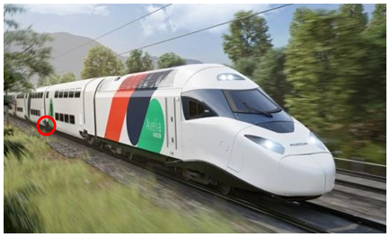
Figure 1The Avelia Horizon. The position of damper bracket between the rear wall of the middle cars is circled (photo by Alstom).
Figure 1 displays the damper bracket and an example of the mounting position at the rear wall of each car body shell of this product; the function is to provide a damping effect in the connection of two adjacent cars.
The middle car has this damper bracket in each corner of one rear wall; this means two connections per middle car and 16 connections in total for a 9-middle-car train.
In the railway industry, we face high static and considerably high dynamic loads. Instead of an integral body concept, car body shells consist of a classical underframe and erected structure. For underframes, the use of mild steel is commonly use, manufactured by sheet metal working (Büttemeier and Strothmann, 2010). The additive manufacturing 316L material does not provide the required material performance. Other stainless steel grades of higher strength are available but they are not cost efficient. Also, the 316L material behaviour in fatigue conditions is not yet well defined. So, a mild steel powder was selected. There are steels available with strength above 1000 MPa. Other steel shows very good ductility, which is important for tensile ductility and to withstand amplitudes in fatigue loading according to EN 13749 (European Committee for Standardization, 2021) and EN 12663-1 (European Committee for Standardization, 2024).
The powder of mild steel, trademark Böhler E185 Ampo, short E185 (Böhler Edelstahl, 2025), is considered a compromise between strength and ductility. Table 1 shows the nominal composition and the composition of the investigated batch. The composition is similar to case hardening steels.
Table 1Composition of the material powder E185; nominal values (Böhler Edelstahl, 2025) and batch values (Böhler et al., 2022).
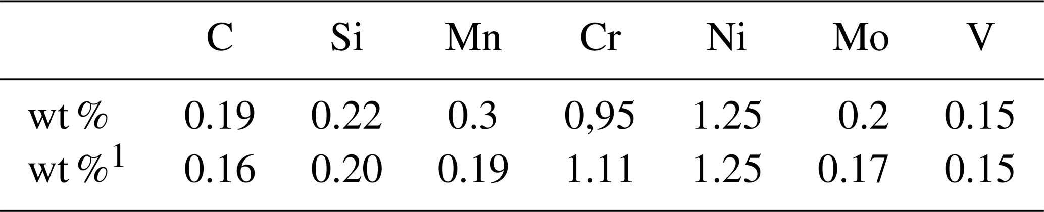
1 Real values of the investigated heat no. CS0038 batch (Böhler et al., 2022).
The rough comparison of mechanical parameters for two steel alloys, given in Table 2, shows higher strength for the mild steel. Important for dynamic loads, the mild steel provides higher strength at acceptable ductility. Ductility is expressed here by elongation A in percent. V-notch impact toughness of E185 is included for information. These values are given to illustrate why the mild steel was targeted for materials selection in the damper bracket use case.
Table 2Comparison between real mechanical values of E185 versus 316L.
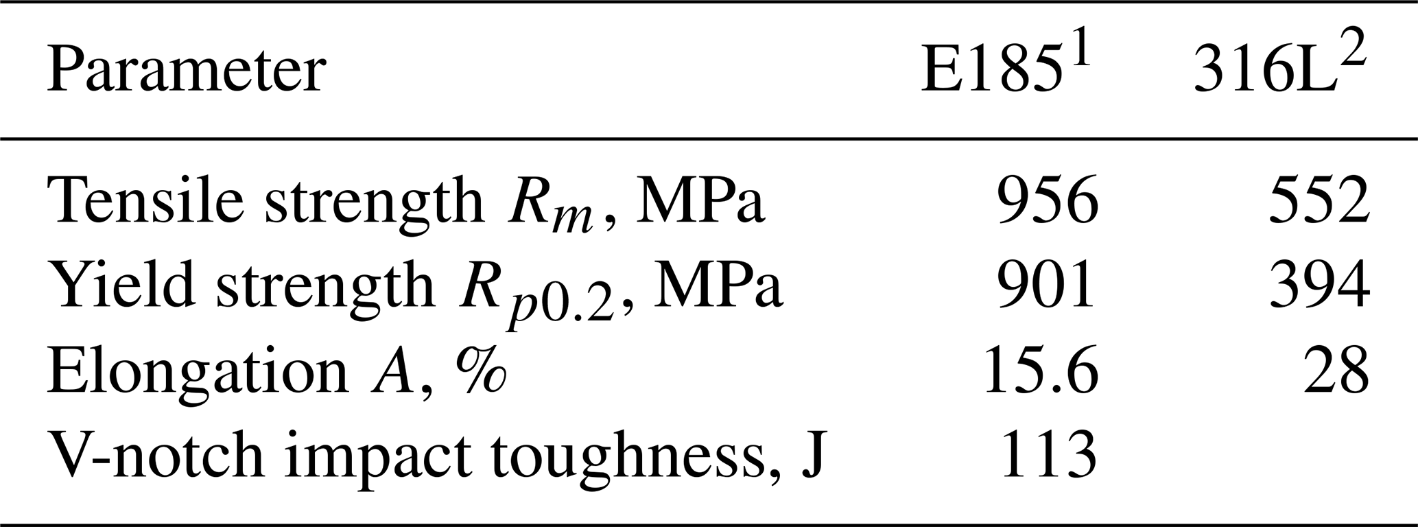
1 Values from Saturne and Alstom (2022a). 2 Values from Erpro and Alstom (2024).
To develop data for the material in a certain printer machine, small samples were printed (also called coupons) to measure the deformation of the material after printing, and use this data to calibrate the print analysis (see Methods).
In order to obtain the data for the calibration of a set of parameters for a specific material, it is necessary to physically print a calibration coupon. After the calibration is complete, the calibration data will be available in the calibrations menu when running an inherent strain analysis on a certain part. A calibration is only valid for the specified printer type, material, and print parameter settings (Altair, 2022). Industrialization of new material starts with test plates and calibration coupons, in order to manage the process specification for various parameters. It was necessary to perform a complete set of material, destructive, and non-destructive tests.
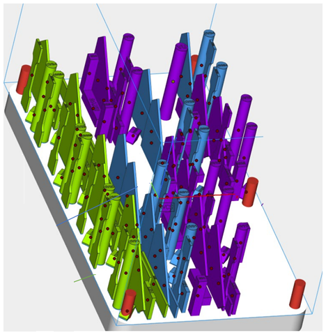
Figure 2The test plate with a set of samples for mechanical tests. The design of test plate was agreed between SNCF, Cetim, and Alstom.
Figure 2 displays several samples for mechanical tests on a test plate. The samples of this building plate/test plate will be used for the following.
As built condition (green samples): mechanical characteristics (Rp0.2, Rm, A %) and metallurgical characteristics (porosity rate)
After stress-relieving treatment (blue): mechanical characteristics (Rp0.2, Rm, A %)
After heat treatment oil quenching 850°/tempering 600° (purple): mechanical characteristics (Rp0.2, Rm, A %, KV).
Methods: based on some experience in the design of brackets, manufacturing constraints were introduced in Altair Hyperworks software to optimize product design. The following parameters are assumed as key parameters.
-
Minimum radius
-
Part orientation
-
Material characteristics
-
Printing sequence
-
Number of printing supports
We adapted the Alstom development process to optimize geometries for additive manufacturing by selective laser melting (SLM).
The subject of optimization was to carry out a new design of a damper bracket oriented towards the SLM process. Based on topological analysis, we planned to design a damper bracket optimized in terms of mass and to support the loads. This will lead to a new concept of damper brackets with variable shape, size, and thickness of the material. This requires a new manufacturing process allowing variable thicknesses and new geometry. A 3D metal AM with SLM is proven for this.
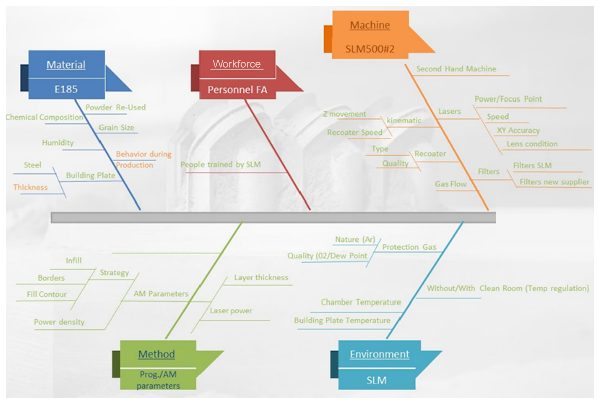
Figure 3Ishikawa diagram displaying various input parameters of the SLM process (Saturne and Alstom, 2022b).
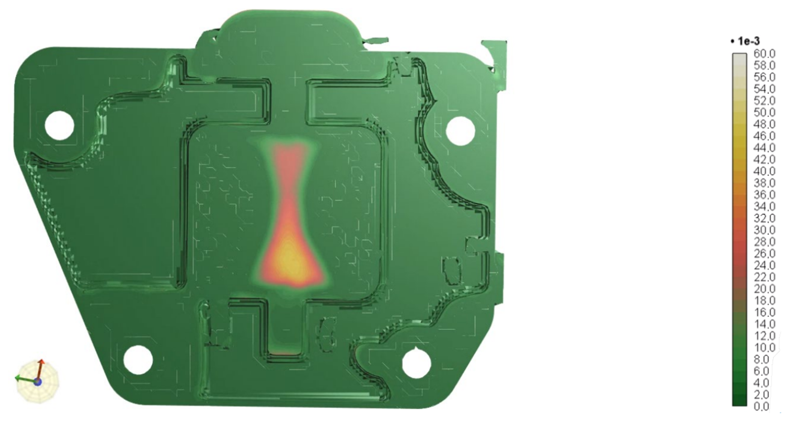
Figure 4The nominal plastic strain in the part at height (z direction) of 8 mm. The colour scale indicates the normal plastic strain between 0.0 % and 6 %.
Since the design of the high-speed train was already performed and completed when the AM redesign started, the constraints and the loads were well defined, even any geometrical restrictions. With Altair Hyperworks the part geometry was generated. A recalculation of the stress in the part during operation shows acceptably low values. The simulation of the build batch, adapted to the foreseen SLM500 machine chamber, did not show any problematic issues. Figure 3 displays a subset of factors, relevant for the result of manufacturing operation. It is obvious that simulation (inner stress as example) is necessary in order to control some of the variety of parameters.
For the simulation of normal plastic strain (after building up, before release from base plate) an example is given in Fig. 4 for one layer of the build process (50 µm per layer, D50 of the powder equal to 29–35 µm).
Figure 4 shows values for normal plastic strain, obtained from the simulation, between 0 % and 4 %. Since the elongation at break is assumed at 15±1 %, the plastic strain during build-up is considered uncritical. The risk of a recoater-crash in the build chamber, caused by deformation of the part, could be ruled out also in this way.
Values for normal plastic strain in the yz plane are shown in Fig. 5. The values, obtained from the simulation, differ between 0 % and 4 % again. Calculations concluded that there was no risk of cracks or critical deformation. Of course, the correct calibration is a prerequisite, according to the above-mentioned procedure with test coupons.
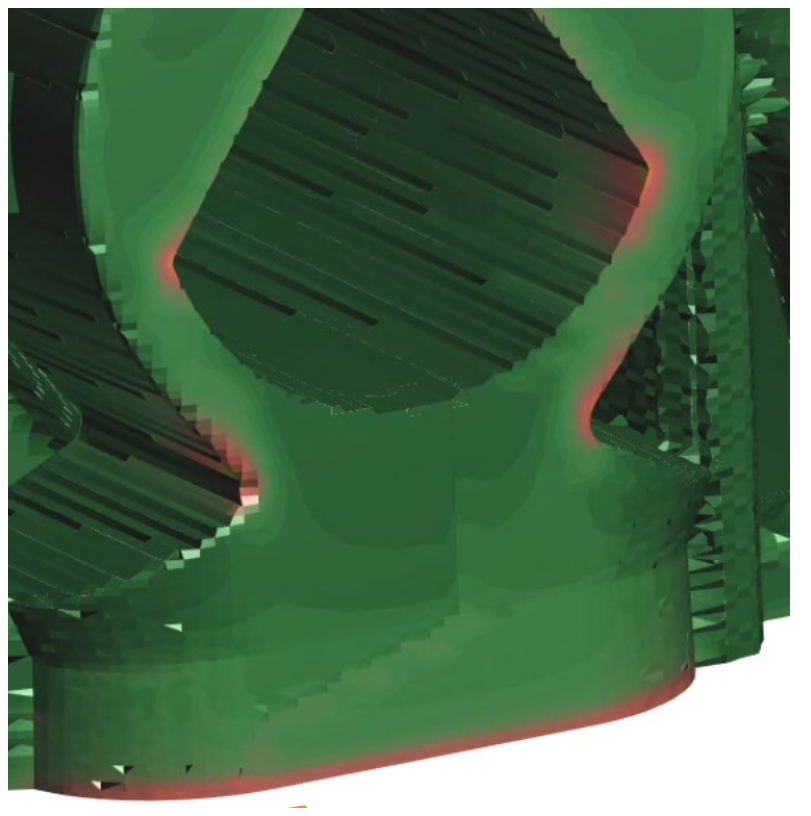
Figure 5The nominal plastic strain in the part in the yz plane. The colour scale indicates the normal plastic strain. Same scale as in Fig. 4.
For mechanical characterization, tensile tests were done according to EN 6892-1 at a temperature of 21 °C. Impact tests were performed after the heating process. The parameters for the heat treatment (quenching temperature and tempering temperature) were investigated in a set of pretests. V-impact test sample type was mm, and the impact test conditions: −20 °C.
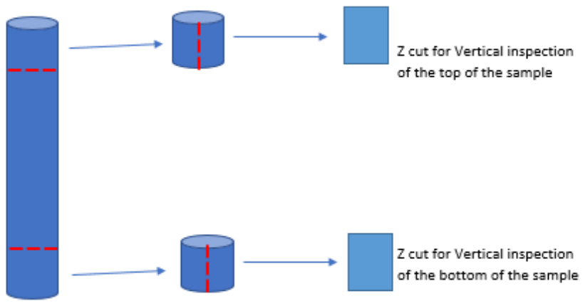
For metallurgical characteristics, porosity was investigated. In addition, some investigations about the congruency of the four installed laser sources were performed. Here, we are focused on material results. Seven cylinders/towers were built (CVH) on a qualification plate: one tower per laser (L1; L2; L3; L4) and on some towers, two overlapping lasers were engaged (1/2; 2/3; 3/4). The state “as built” was without any heat treatment. Figure 6 illustrates the two inspected areas for each sample tower.
Further samples treatment included polishing up to 3 µm and macro inspection with magnification ×10 to assess the porosity distribution for a surface field of about 30 mm2. This inspection enables the inspector to detect potential cumulated defects or contour porosities. Later micro inspection was undertaken with magnification of ×100 to assess the porosity rate according to Alstom purchasing standard, which was 0.5 % max for class H in area of 1 mm2 (Alstom, 2022). Class H means that the item is relevant to safety.
For validation of material properties at the part level and of the design, a fatigue test was performed. Figure 7 shows the part in the test rig. Static load cases in preparation of the fatigue test are defined as −31 and +31 kN in the vehicle's X direction.
Fatigue load cases are defined. The load stages are given in Table 3.
Table 3Overview fatigue load stages1.
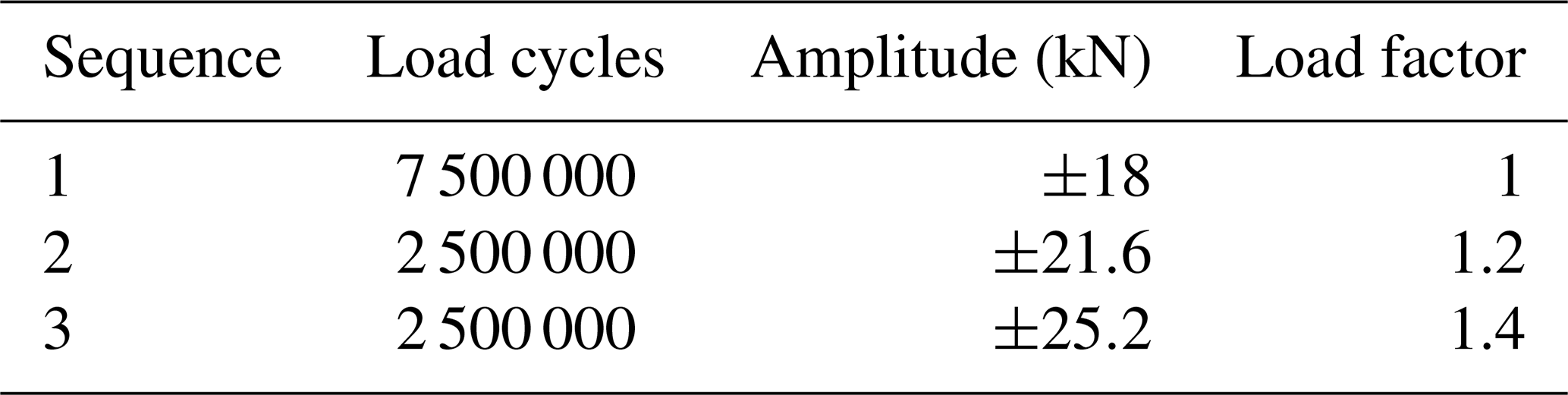
1 Values from IMA Dresden and Alstom (2022).
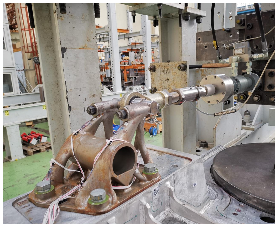
Table 4Values of mechanical tests1, mean, and σ of seven samples.
1 Values from Saturne and Alstom (2022a).
A damper bracket was designed (left-hand and right-hand sides) for the technology of additive manufacturing. This adapted design could be successfully validated.
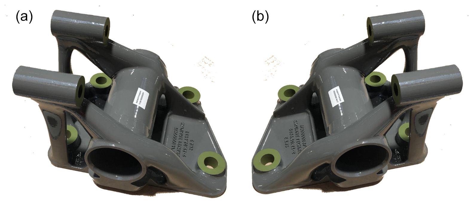
Figure 8The damper bracket (a, b), coated (Primer 2K-EP/Thick varnish 2K-EP), ready for assembly in a high-speed train.
Figure 8 displays the two variants of the redesigned part (left-hand and right-hand sides). Figure 9 compares (a) the conventional design after machining before coating with (b) the design, adapted for additive manufacturing, after machining and coating. Since the load paths are optimized, there is no surplus material in the design of the part. The weight could be reduced significantly from 25 to 12 kg.
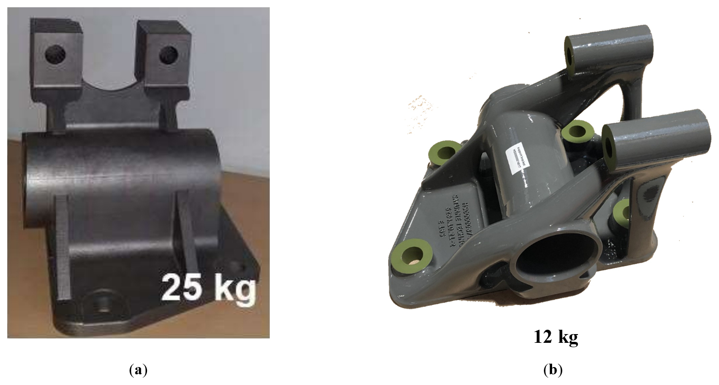
Figure 9The damper bracket: (a) as conventional part, designed for casting or sheet metal welding; (b) as designed for the possibilities of additive manufacturing.
The common service life of rolling stock is approx. 30 years (PDSCPD, 2023). Detailed cost calculations were presented by Fassbinder (2019) and Frensch (2005). Across the energy mix and some further simplifications, the costs for 1 kg of rolling stock can be assumed to be EUR 1 yr kg−1. Assuming the possibility of saving the operating costs (mostly energy for the drive) of 1 kg of a rail vehicle during its service life of up to 30 years. Then, this means cost improvements of EUR 30 kg−1 over 30 years. It can be discounted to EUR 15 kg−1 on the day of commissioning. With the newly designed damper bracket, a weight saving of 13 kg per unit was achieved. This means a discounted operating cost saving of EUR 195 per unit (please note that the actual values may differ from this assumption). As there are 16 brackets on a train, the lightweight component saves 208 kg per train (nine middle cars). That is EUR 3000 per train.
3.1 Dimensional characteristics
Dimensional/geometrical inspection was done with a Hexagon Romer Absolute Arm. The applied tolerances for the scanning are ±1 mm (green segments). With the measuring device, a point cloud of the surface of the damper brackets is captured. This point cloud is in superposition with the CAD model. Figure 10 displays the difference figure after superposition. The distances between point cloud and CAD model are colour coded. The scale, used here, displays in green, when the difference is less than 1.0 mm. The grey areas indicate an incompletely scanned surface. However, these are only small areas next to the well-scanned areas. There is therefore no risk of unexpectedly large deviations from the model. The captured surface fits well the CAD model inside the specified tolerances.
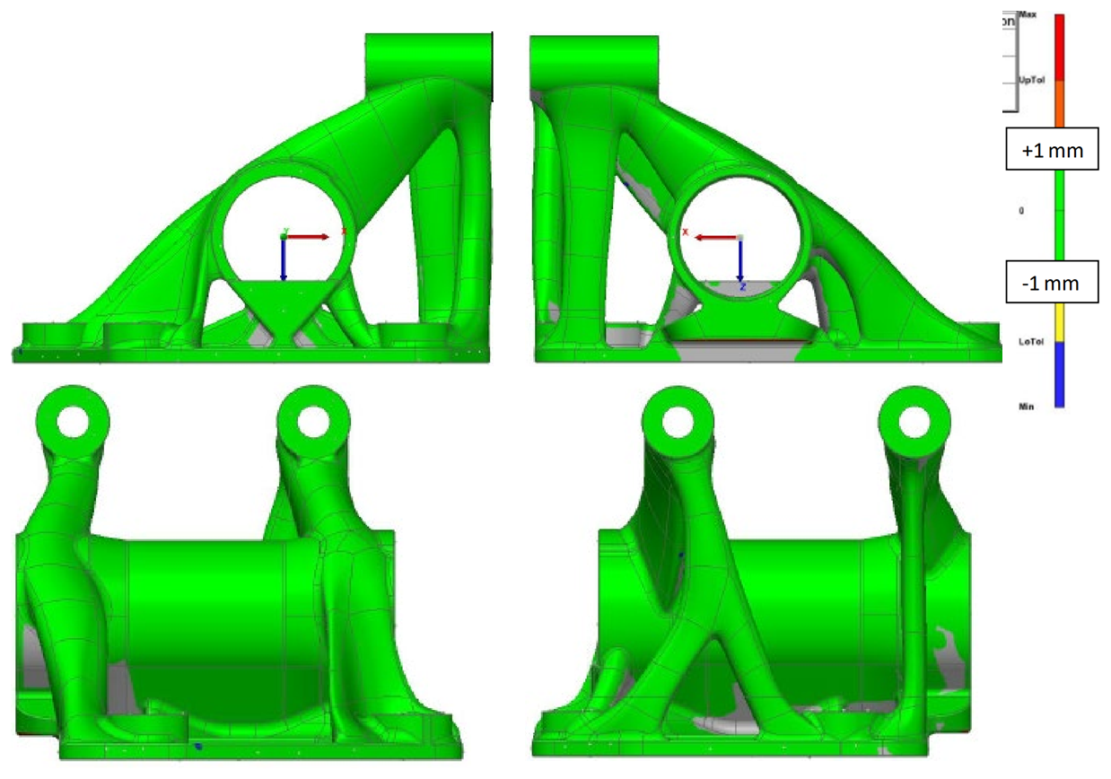
The results of dimensional inspection of the damper brackets met the specification. This is important to prevent that deviations in geometry influence the results of further tests.
3.2 Materials properties
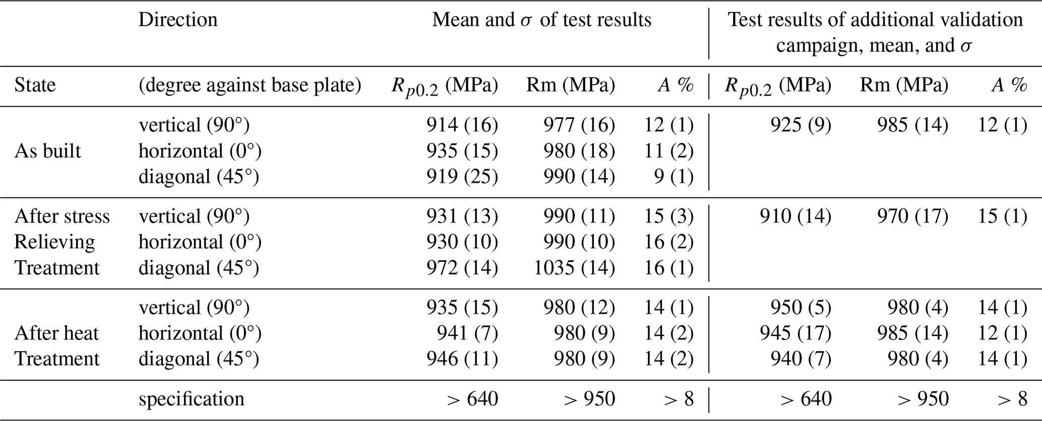
3.2.1 Mechanical values
Table 4 displays the values of mechanical tests. Some variations in the print direction (vertical (90°), horizontal (0°), diagonal (45°), degree against base plate), and state (as built, after stress-relieving treatment, after heat treatment) were permitted. The quantity of each state and direction in the first campaign is seven samples. It is worth mentioning that each single value and the mean value are above the specification. Since the safety level is high, some values were validated by another test campaign, in addition to the samples in the first test campaign.
Impact tests were performed after heat treatment at impact test conditions of −20 °C. The sample size was mm. The sample condition was heat treated, quenched, and tempered. The results of two test campaigns are shown in Table 5 with values from Saturne and Alstom (2022a). Impact values vary significantly but nevertheless meet the specification of >27 J.
Table 5Comparison of two test runs, impact values of E185, test run no. 1 includes three samples, test run no. 2 was performed with six samples.
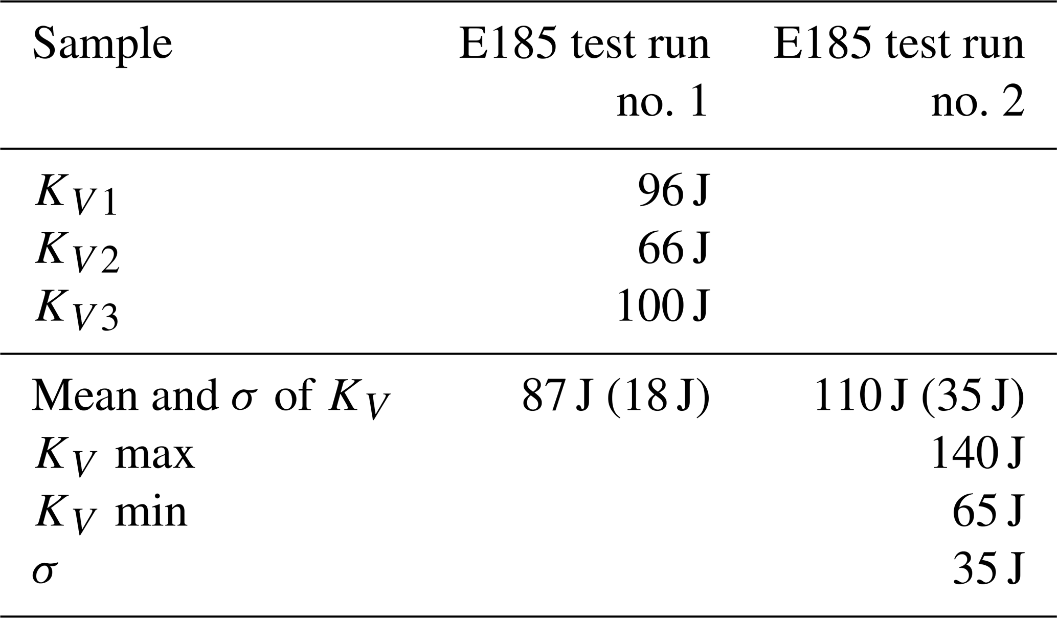
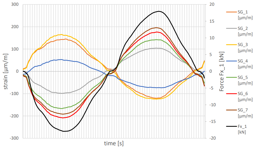
Figure 11Dynamic measurement. Situation at time point 4 million load cycles; test frequency was 8 Hz (IMA Dresden and Alstom, 2022).
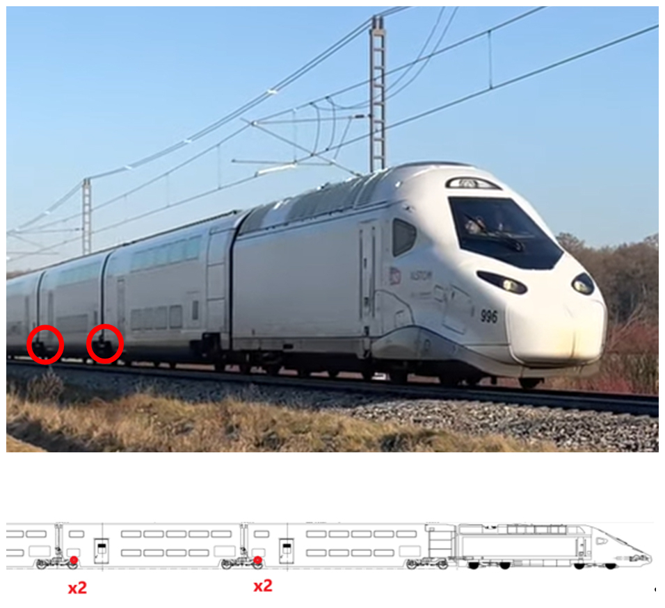
Figure 12Avelia-Horizon on track and a sketch to show the bracket position between middle cars (photo by Alstom).
3.2.2 Porosity
Macro inspection with magnification ×10: no defect >600 µm. There were no contour porosities and some isolated small porosities.
Micro inspection with magnification of ×10: the average porosity in the rated fields is 0.3 %. This average porosity and the worst porosity in the rated field show a size below the maximum specified, so the specification was met.
3.3 Part properties
To show that the behaviour of the complete part is according to expectations and specifications, a static test and a dynamic test were performed (IMA Dresden and Alstom, 2022) at a lab accredited according to ISO/IEC 17025.
The result of the static load of the complete part in the test rig, equipped with the strain gauges can be summarized with the maximum value of 388.34 µm m−1. The strains at each measuring point always behaved linearly.
Figure 11 illustrates the dynamic measurement. The situation after 4 million load cycles is presented. The test frequency was 8 Hz. The strain gauge signals follow the exciting force (described as Fx_1 in the legend). The individual load cycles were each completed in sinusoidal form with the amplitude given in Table 3. During the entire test campaign, a total of six magnetic inspections according to ISO 9934 were performed. No changes in the sample part could be detected.
In total, two static load cases and three fatigue load stages were performed. The sample successfully completed the test campaign, and the inspections did not reveal any negative findings.
The investigated part is a damper bracket component of a high-speed train (up to 350 km h−1). One train usually consists of two end cars and nine middle cars (so 16 brackets, since two brackets are placed between two middle cars). The lightweight part (13 kg weight saving per part) will save 208 kg per train. Figure 12 shows the train on a track.
With the test results obtained, the design authority was able to confirm approval for serial use of the damper bracket. A train was fully equipped with the redesigned and additive manufactured damper bracket. Concerns about the maturity of additive manufacturing parts used with dynamic loading have be addressed by this project.
The ambition to save weight, even for dynamically loaded metallic components on railway vehicles, could be satisfied by the adaptation of SLM technology. A mild steel powder was validated for high-speed train dynamically loaded damper bracket application. For specified mechanical values, the conformity could be confirmed. Since the components are dynamically loaded, a fatigue test was performed. The results of inspections (mechanical and dimensional) of the products meet the requirements. Conformity with specification could be confirmed even for the dynamic load cases. Meanwhile, the trains with new design for AM were in operation for some thousands of kilometres without any problems. To meet the expectations in static and dynamic load cases, Alstom has used mature software tools for design and optimization. This single use case defines the design path and the validation path for more use cases in the railway industry, at least for rolling stock. Further analyses will provide explanations for the significant variety of values in Table 5.
Resuming the cost structure of SLM manufactured components, the base plate cost is a considerable factor. When we started thinking about different materials used for the build plate, Alstom took material costs into account. The obligation to provide base plates of the same material type unfortunately increased the project cost. The ambition to save costs leads to a base plate made of standard mild steel. The material of the same type of further additive manufacturing is applied by friction stir welding (German Patent and Trade Mark Office, 2020). The advanced base plate for additive manufacturing, corresponding device and process are described there in DE102019115770A1 and DE202019005706U1.
The investigated friction stirring welding technology was later used for description of a method for processing wheels of railway vehicles (European Patent Office, 2019). In short, add a protective layer to prevent or to repair any wear. Please find the details in EP3695933B1.
| 2K-EP | two components epoxy polymer |
| σ | deviation |
| A | Elongation |
| AM | additive manufacturing |
| CVH | complete volume hatched |
| D50 | diameter 50 % of powder particles are smaller |
| DED | direct energy deposition |
| FDM | fused deposition modelling; |
| EDM | electrical discharge machining |
| Hz | Hertz |
| J | Joule |
| kN | Kilonewton |
| Kv | Charpy impact v notch sample |
| Rp0.2 | yield strength |
| Rm | tensile strength |
| SLM | selective laser melting |
| WAAM | wire arc additive manufacturing |
The test reports referred to here are available via correspondence.
Conceptualization, SG; methodology, PG; supervision, AF; writing – original draft, UJ. All authors have read and agreed to the published version of this article.
The contact author has declared that none of the authors has any competing interests.
Publisher’s note: Copernicus Publications remains neutral with regard to jurisdictional claims made in the text, published maps, institutional affiliations, or any other geographical representation in this paper. While Copernicus Publications makes every effort to include appropriate place names, the final responsibility lies with the authors.
The presented materials and reports were kindly provided by Altair, Böhler, Erpro, Ima, Saturne. The build shop was performed at SLM500 machines at Saturne facilities. The authors would like to express many thanks for fruitful cooperation. This article is a revised and expanded version of a paper entitled “Saved weight by 3D printing of a damper support bracket for a high-speed train”, which was presented at Lightcon 2023, in Hanover, 2023 (Jurdeczka et al., 2023).
This paper was edited by Jeong Hoon Ko and reviewed by Dirk Simon and two anonymous referees.
Alstom: Purchasing Specification for Additive Manufactured Parts, metal, Internal Standard DTRF150266-1, https://archive.org/details/eng-rsc-en-dr-dtrf-150266-1-2023-08-11 (last access: 14 October 2025), 2022.
Altair: Coupon calibration routine, https://2022.help.altair.com/2022/inspire/en_us/topics/inspire/3Dprint/calibration_3Dprint_t.htm (last access: 7 August 2025), 2022.
Armstrong, M., Mehrabi, H., and Naveed, N.: An overview of modern metal additive manufacturing, Journal of Manufacturing Processes, 84, 1001–1029, https://doi.org/10.1016/j.jmapro.2022.10.060, 2022.
Böhler Edelstahl: Material Data Sheet E185, https://www.bohler-edelstahl.com/app/uploads/sites/248/productdb/api/e185-ampo_de_at.pdf (last access: 7 August 2025), 2025.
Böhler, Saturne and Alstom: Materials Test Report accord, EN 10204 2.2, No. 972637/C3/2022.07.29, https://archive.org/details/archive-file-for-internal-test-reports-ms-2024-232_202510 (last access: 14 October 2025), 2022.
Büttemeier, M. and Strothmann, M.: Schweißtechnisches Handbuch Schienenfahrzeugbau, DVS Media GmbH, ISBN 978-3871552007, 2010.
Erpro and Alstom: Material Test Report, as part of FAI Nr. 2024_03_QUA_SLZ_FRM_033_V1_DTR0000567000_2024 08 03, Internal report, https://archive.org/details/archive-file-for-internal-test-reports-ms-2024-232_202510 (last access: 14 October 2025), 2024.
European Committee for Standardization: EN 13749:2021, Railway applications – Wheelsets and bogies – Method of specifying the structural requirements of bogie frames, 2021.
European Committee for Standardization: EN 12663-1, Railway applications – Structural requirements of railway vehicle bodies – Part 1: Locomotives and passenger rolling stock (and alternative method for freight wagons), 2024.
European Patent Office: Method for processing wheels of railway vehicles, EP3695933 (B1), https://worldwide.espacenet.com/patent/search/family/065717939/publication/EP3695933B1?q=EP3695933B1 (last access: 7 August 2025), 2019.
Fassbinder, S.: Wie Energie-effizient ist der Bahnverkehr wirklich?, Deutsches Kupferinstitut, https://www.static.tu.berlin/fileadmin/www/10002264/ews/2019-wise/2020-01-13-folien.pdf (last access: 7 August 2025), 2019.
Frensch, M.: Ermittlung von wirtschaftlich und betrieblich optimalen Fahrzeugkonzepten für den Einsatz im Regionalverkehr, Schriftenreihe des Instituts für Verkehr Fachgebiet Bahnsysteme und Bahntechnik Heft B7, Darmstadt, ISSN 1614-9300, 2005.
German Patent and Trade Mark Office: Base plate for additive manufacturing, corresponding device and process, DE102019115770 (A1) and also DE202019005706 (U1), https://depatisnet.dpma.de/DepatisNet/depatisnet?action=pdf&docid=DE202019005706U1&xxxfull=1 (last access: 7 August 2025), 2020.
IMA Dresden and Alstom: Test report TGV2020 – Fatigue Test of Damper Support 3D-Printed, R021/22, https://archive.org/details/archive-file-for-internal-test-reports-ms-2024-232_202510 (last access: 14 October 2025), 2022.
Jurdeczka, U.: Large components, made with Additive Manufacturing for rolling stock at ALSTOM, rapid.tech and FabCon, Erfurt Germany, https://doi.org/10.13140/RG.2.2.13159.01448, 2023.
Jurdeczka, U., Fussel, A., and Benizeau, F.: Saved weight by 3D printing of a damper support bracket for a high speed train, LIGHTCON-Conference at Hannover, https://doi.org/10.13140/RG.2.2.18588.40327, 2023.
Mansoura, A., Dehghan, S., Barka, N., and Sattarpanah Karganroudi, S.: Investigation into the effect of process parameters on density, surface roughness, and mechanical properties of 316L stainless steel fabricated by selective laser melting, The International Journal of Advanced Manufacturing Technology, 130, 2023, https://doi.org/10.1007/s00170-023-12865-1, 2023.
PDSCPD: Policy Department for Structural and Cohesion Policies, Directorate-General for Internal Policies, PE 747.263: Perspectives for the rolling stock supply in the EU, https://www.europarl.europa.eu/RegData/etudes/STUD/2023/747263/IPOL_STU(2023)747263_EN.pdf (last access: 7 August 2025), 2023.
Saturne and Alstom: Materials Test Certificate according EN 10204 3.1, SAT.ALST.2946.29.11.21, https://archive.org/details/archive-file-for-internal-test-reports-ms-2024-232_202510 (last access: 14 October 2025), 2022a.
Saturne and Alstom: Internal Report Support Bracket, #22.11.001, https://archive.org/details/archive-file-for-internal-test-reports-ms-2024-232_202510 (last access: 14 October 2025), 2022b.
Selmi, H., Brousseau, J., Caron-Guillemette, G., Goulet, S., Desjardins, J., and Belzile, C.: Weldability of 316L Parts Produced by Metal Additive Manufacturing, Journal of Manufacturing and Materials Processing, 7, 71, https://doi.org/10.3390/jmmp7020071, 2023.
Tan, J. H., Wong, W. L., and Dalgarno, K. W.: An overview of powder granulometry on feedstock and part performance in the selective laser melting process, Additive Manufacturing, 18, 228–255, https://doi.org/10.1016/j.addma.2017.10.011, 2017.