the Creative Commons Attribution 4.0 License.
the Creative Commons Attribution 4.0 License.
 | 30 Aug 2024
Design principles and kinematic analysis of a novel spherical 2-degree-of-freedom (DOF) parallel mechanism
Xuechan Chen
Chao Xin
Zhen Zhang
Yu Guo
An Yin
Ziming Chen
The spherical parallel mechanism (SPM) offers several advantages such as high stiffness, precision, a large workspace, immunity to interference, and simple kinematic calculations. Consequently, SPM finds extensive applications in fields like surgical robots, exoskeleton robots, and others. This paper proposes a design principle based on the virtual middle-plane constraint method, which integrates the branch constraint of the mechanism into the intermediate virtual constraint plane. On the one side, a symmetric spherical 3R branch consisting of two spherical links is provided to offer 3 rotational degrees of freedom (DOFs). On the other side, a constraint force located on the middle plane constrains 1 rotational DOF, enabling the end effector link to achieve 2 DOFs. Several symmetrical SPMs are synthesized based on the constraint force provided by the branches. The mechanism can achieve continuous motion from an initial position to a final position by undergoing a single equivalent rotation around an axis on the virtual symmetric plane passing through the center. The forward and inverse kinematic solutions and the velocity Jacobian matrix of the symmetrical SPM are determined. The workspace of the mechanism is obtained by considering inverse kinematics and link interference conditions. The dexterity and force/torque transfer performance of the mechanism within a certain range are analyzed. The correctness of the kinematics of the symmetrical SPM is demonstrated through simulation analysis and prototype experiment. This research lays a foundation for motion planning and dynamic analysis of this kind of mechanism by providing a variety of configurations for practical applications.
- Article
(7600 KB) - Full-text XML
- BibTeX
- EndNote


The parallel mechanism has the advantages of high bearing capacity, high structural stiffness, and compact structure. The spherical parallel mechanism (SPM) is a special spatial parallel mechanism. Its structural feature is that all the axes of revolute joints intersect at one point, and the end effector can rotate freely around that point. The SPM plays an indispensable role in practical applications and has been widely used in many fields, such as the azimuth tracking system (Luo et al., 2014), the bionic robot (Kumar et al., 2017), and medical devices (Cao et al., 2019; Saafi et al., 2018). When applied in imaging devices, spherical parallel mechanisms excel in fulfilling a range of needs, from surveying surrounding environments and coarse positioning to subsequent autonomous fine adjustments for the optimal observation of target objects. In contrast to traditional imaging setups that are limited to adjusting angles in horizontal and vertical directions, spherical parallel mechanisms offer simultaneous 2-degree-of-freedom (DOF) adjustments on a spherical surface, providing superior imaging perspectives.
The current research on SPMs mainly focuses on 2-DOF SPMs and 3-DOF SPMs, and some research results have been achieved in configuration synthesis, kinematic analysis, and dynamic analysis. The theoretical research and practical engineering applications of 3-DOF SPMs are relatively mature – for example, the typical 3-RRR SPMs. Gosselin and Hamel (1994) developed the well-known agile eye device. In addition, various modifications of this mechanism have been proposed and its applications have been continuously expanded. In the field of bionic robots, Liu et al. (2002) used a spherical 3-RRR mechanism as the shoulder and wrist joint mechanisms to design a 7-DOF redundant humanoid arm based on a series–parallel structure. In the field of rehabilitation medicine, Li and Payandeh (2002) applied the spherical 3-RRR mechanism to the laparoscopic surgical robots and optimized its workspace. French scholar Saafi et al. (2015) proposed a medical device based on tactile feedback and put forward an optimal torque distribution method. The performance of the SPM was improved by adding redundant actuators, and the geometric parameters were optimized to eliminate singularities. Zhang (2016) used a decoupled 3-RRR spherical parallel mechanism for the design of a launch platform. Zhou and Ge (2017) added a 3R branch as the design basis and obtained various redundantly actuated spherical 3-DOF mechanisms for flight simulators. Detailed analyses and comparisons of their DOF properties and workspace motion properties were conducted. The development of other types of 3-DOF SPMs has also been very rapid. Enferadi and Nikrooz (2018) conducted kinematic and workspace analyses on the 3-UPS/S SPM and used genetic algorithms to optimize the dimensions of the manipulator for single-objective and multi-objective optimization. Chang et al. (2022) proposed a novel three-branch spherical parallel mechanism with semi-decoupled characteristics, which has 3 rotational DOFs around the X, Y, and Z axes. W. B. Chen et al. (2022) conducted research on the parameter optimization method of a prosthetic shoulder joint mechanism based on a 3-RRR asymmetric SPM, with the goal of achieving the structure and function of the human shoulder joint. Arredondo-Soto et al. (2023) presented the compliant version of the 3-RRR SPM known as agile eye, which achieves motion manipulation through the utilization of compliant joints and rigid elements. This design offers advantages such as weight reduction, friction elimination, miniaturization, and enhanced precision.
In many fields, the use of a 2-DOF SPM is sufficient to meet the requirements. Compared to 3-DOF SPMs, 2-DOF SPMs have lower manufacturing costs and are easier to control. For instance, pointing mechanisms (Yu et al., 2016) can be utilized for sphere-based carving machines, satellite-antenna azimuth tracking, and automatic tracking devices on the ground for different types of aircraft. The spherical 5R mechanism serves as a typical representative of a 2-DOF SPM. Saiki et al. (2021) designed a bidirectional oscillating 2-DOF SPM with an active arc slider. Based on the new design concept of a “linear input–rotational output” chain, 2-DOF decoupled parallel mechanisms with a spherical working space are designed (Yu et al., 2020). Unlike existing methods that exploit singularity in parallel mechanisms for synthesizing reconfigurable parallel mechanisms, we proposed a set of triangular decoupling conditions for spherical parallel mechanisms. These conditions facilitate the synthesis of a drivetrain-based reconfigurable parallel spherical joint (Hu and Liu, 2022) capable of achieving one-dimensional fixed-axis rotation, one-dimensional variable-axis rotation, and two-dimensional and three-dimensional rotations. By incorporating a passive US limb into a 3-RPS parallel mechanism, a novel 3-RPS/US parallel mechanism with 2 DOFs has been obtained that is composed of one revolute, one prismatic, and one spherical joint limb (Li et al., 2022) for the 3-RPS portion and universal joints and spherical joints for the US portion. This enhancement increases the payload capacity of the mechanism, making it suitable for potential applications such as dual-axis tracking photovoltaic supports. A basic design method for a 2-DOF SPM bending dual-axis oscillating mechanism with a circular arc slider (Naoto et al., 2021) as input is proposed. The swing area of the passive link is small, allowing for infinite rotation around a certain axis without collision or transitioning into a single posture. Dong et al. (2012) analyzed the kinematics, singularity, and workspace of a class of 2-DOF mechanisms. Kim and Oh (2014) deformed the spherical 5R mechanism; designed the spatial self-adaptive finger clamp; and conducted a constraint analysis, optimization design of the structure, and grasping experiment on it. Cao et al. (2019) obtained a three-rotation-and-one-translation (3R1T) manipulator for minimally invasive surgery by connecting the revolute pair and the prismatic pair to a 2-DOF SPM and analyzed its kinematics and singularity. Chablat et al. (2021) designed a 2-UPS-U 2-DOF SPM with a predetermined regular workspace shape to manipulate an endoscope for assisting in ear surgery.
In summary, many scholars have conducted comprehensive research on two typical SPMs. It can be seen that SPMs have great potential application value. However, most of the research on 2-DOF SPMs only analyses the proposed mechanisms and does not mention the design principles of their configurations. Therefore, we proposed a new design principle for a symmetrical 2-DOF SPM. Structurally symmetric parallel mechanisms with isotropic symmetry and fewer DOFs exhibit greater potential in applications. The symmetrical SPM can realize continuous rotation around any line on the middle plane that passes through the rotation center of the spherical mechanism. The axis of rotation is fixed during rotation, and the mechanism is symmetric at all times during movement, which means that any form of motion of the mechanism can be transformed into a rotation with a fixed axis. This study establishes the theoretical foundation for the design of parallel mechanisms and further enriches the research on parallel mechanism systems.
In this paper, the design principle of a novel 2-DOF SPM with a symmetrical structure is proposed, a series of SPMs without over-constrained force/torque are synthesized, and the kinematic and static characteristics of one of the mechanisms are analyzed in detail. The paper is organized as follows: Sect. 2 analyzes the design principle and structure design of the symmetric SPM. In Sect. 3, the models of forward kinematics and inverse kinematics are established and the Jacobian matrix of the mechanism is obtained. The performance of the symmetrical SPM is analyzed in Sect. 4. In Sect. 5, the kinematic simulation and prototype experiment of the SPM are conducted. Conclusions are presented in Sect. 6.
2.1 Analysis of the design principle of the symmetric SPM
The motion of the spherical mechanism revolves around a fixed point which is called the rotation center of the mechanism. There are two requirements in order for the SPM to maintain symmetry during motion, as shown in Fig. 1. Firstly, the overall structure of the mechanism must be symmetrical about a plane which is called the middle plane of the mechanism. Secondly, the rotation axis of the end effector of the spherical mechanism must be located on the middle plane and pass through the rotation center of the mechanism.
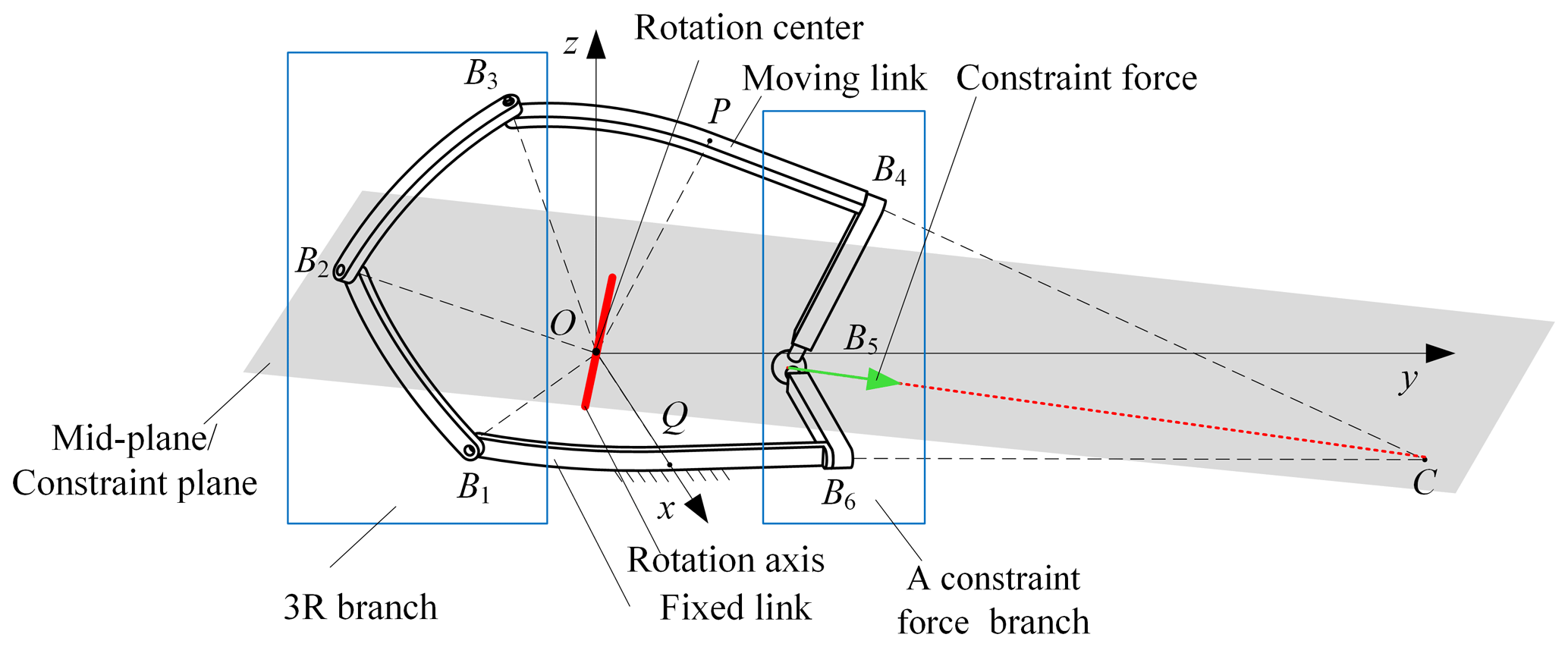
In order to realize the symmetrical movement of the 2-DOF spherical mechanism, its design principle is to limit the end effector's 3 translational DOFs and 1 rotational DOF about the axis perpendicular to the middle plane, and the structure of the mechanism is symmetrical about the middle plane.
Therefore, the specific design principle of a 2-DOF spherical parallel mechanism forms a 3R mechanism for one side of the linkage, providing 3 rotational DOFs. To achieve 2 rotational DOFs, another branch is needed to provide a constraint force that does not pass through the center of the sphere and is located on the middle plane. This constraint can be equivalent to a constraint torque relative to the rotation center, O, and perpendicular to the middle plane. Therefore, the constraint force provided by the constraint force branch, combined with the constraint screw provided by the spherical 3R branch limits the rotation of the end linkage around the axis perpendicular to the middle plane, resulting in a symmetric spherical mechanism with 2 DOFs. The specific requirements are as follows: (1) ensuring that the angle between the fixed link and the end link with the middle plane remains constant during the motion of the mechanism and arranging them symmetrically. (2) The joint axes of the 3R branch on the left side intersect at the center of the sphere. (3) The constraint force provided by the constraint branch on the right side lies on the middle plane.
2.2 Structural design of the symmetric SPM based on branch constraints
According to the design principle of the symmetrical SPM based on the branch constraint, three non-coplanar constraint forces intersecting at one point and a constraint torque that is perpendicular to the middle plane are provided by the branches connecting the end effector and the base, whose structure is symmetrical.
The simplest branch that can provide three non-coplanar constraint forces that intersect at one point is the spherical 3R branch. Assuming that one of the branches connecting the end effector and the base is the spherical 3R branch, its coordinate system is established as shown in Fig. 2; the B1B2 link and B2B3 link form a 3R branch.
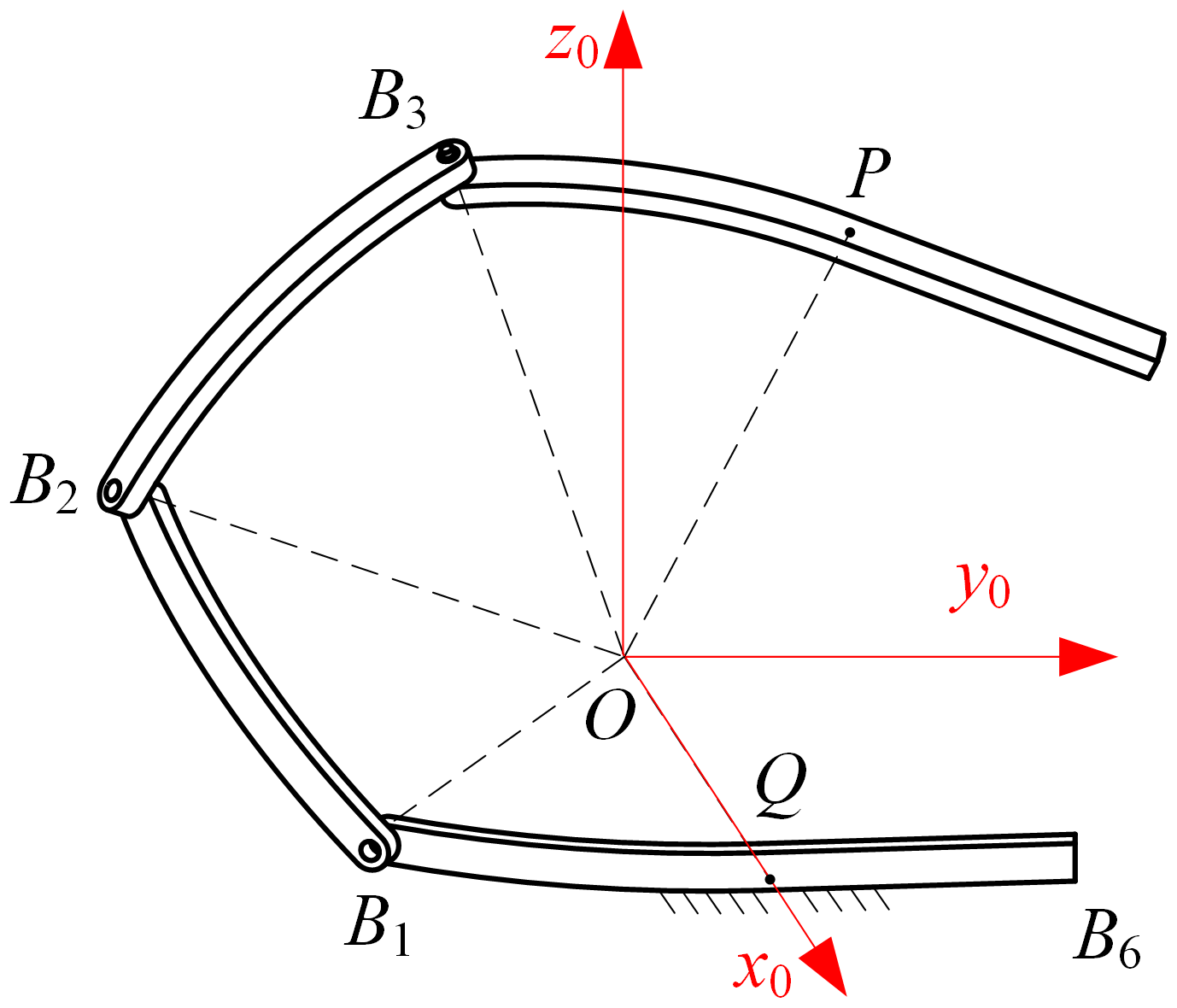
The x0 axis points from point O to point Q (the mid-point of the base), the z0 axis is perpendicular to the plane that the base is lying on, the positive direction is upward, and the y0 axis is determined by the right-hand rule. The kinematic screw system of the spherical 3R branch is
where parameters o1, p1, o2, p2, q2, o3, p3, and q3 are related to the position and direction of the revolute joints B1, B2, and B3.
The constraint screw system of the spherical 3R branch is
Based on screw theory, the constraint screws in Eq. (2) correspond to the constraint forces which pass through O and are coaxial with the x0 axis, y0 axis, and z0 axis, respectively. The 3 translational DOFs in the directions of the axes are limited by the three constraints. Moreover, a branch that can provide a torque perpendicular to the middle plane is needed.
2.3 Design of a symmetric SPM based on the single-constraint force branch
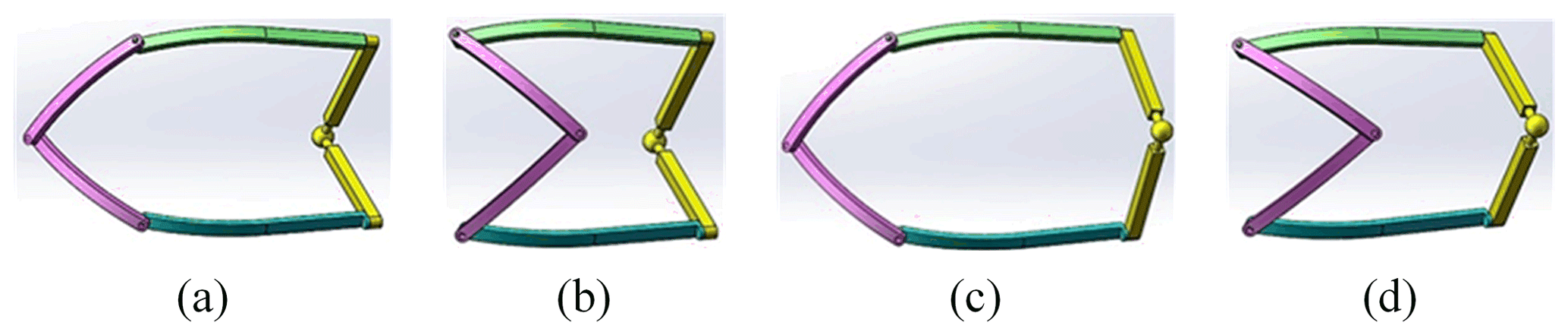
In order to provide a mechanism without over-constrained force/torque, the branch providing only one constraint torque is considered first. However, Zhao et al. (2004) found that there are few branches suitable for the design of the symmetrical SPM, so the branches that provide only one constraint force are considered. The design requirement of the branches with a single constraint force is that the constraint force provided by the branch is located on the middle plane and does not pass through the rotation center. The constraint force can be equivalent to the constraint torque perpendicular to the middle plane. Chen et al. (2016) synthesizes a series of branches providing a constraint force, among which the branches satisfying structural symmetry are shown in Table 1.
Table 1Branches providing a constraint force and symmetry about the middle plane.
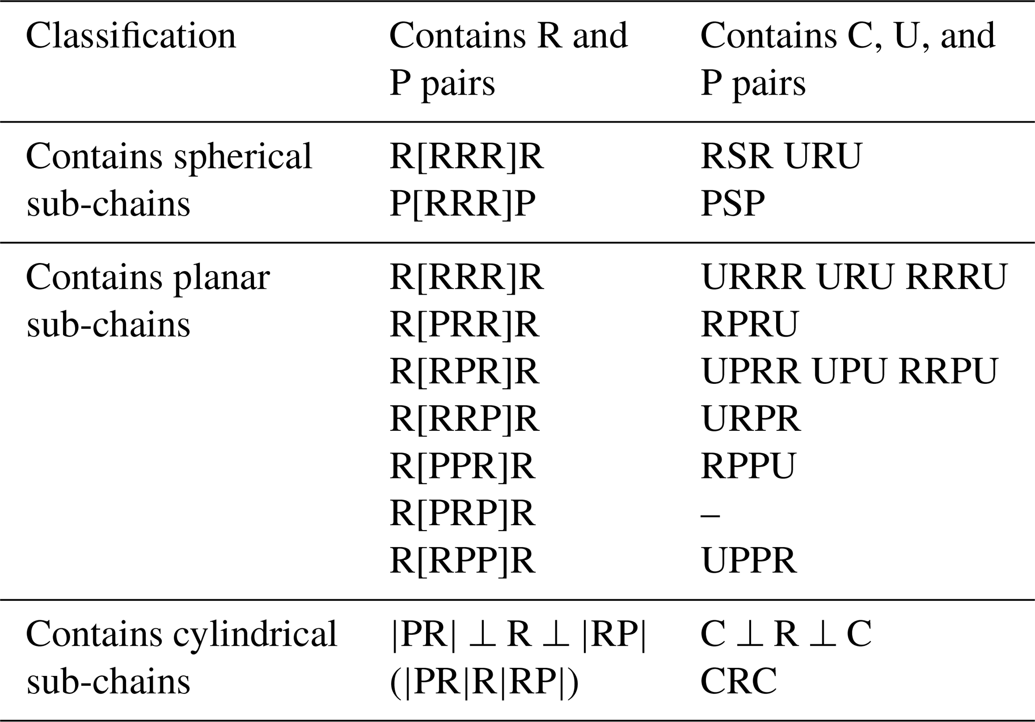
There exists a well-defined geometric correlation between the force or torque of the branch constraint and the motion pairs of said branch (Chen et al., 2016). In branches with symmetrical structures, the constraint force can effectively be confined to the middle plane by judicious arrangement of the motion pairs. To comply with design principles, this paper outlines the structural design of symmetrical SPMs utilizing the RSR, PSP, URU, and CRC branches, respectively.
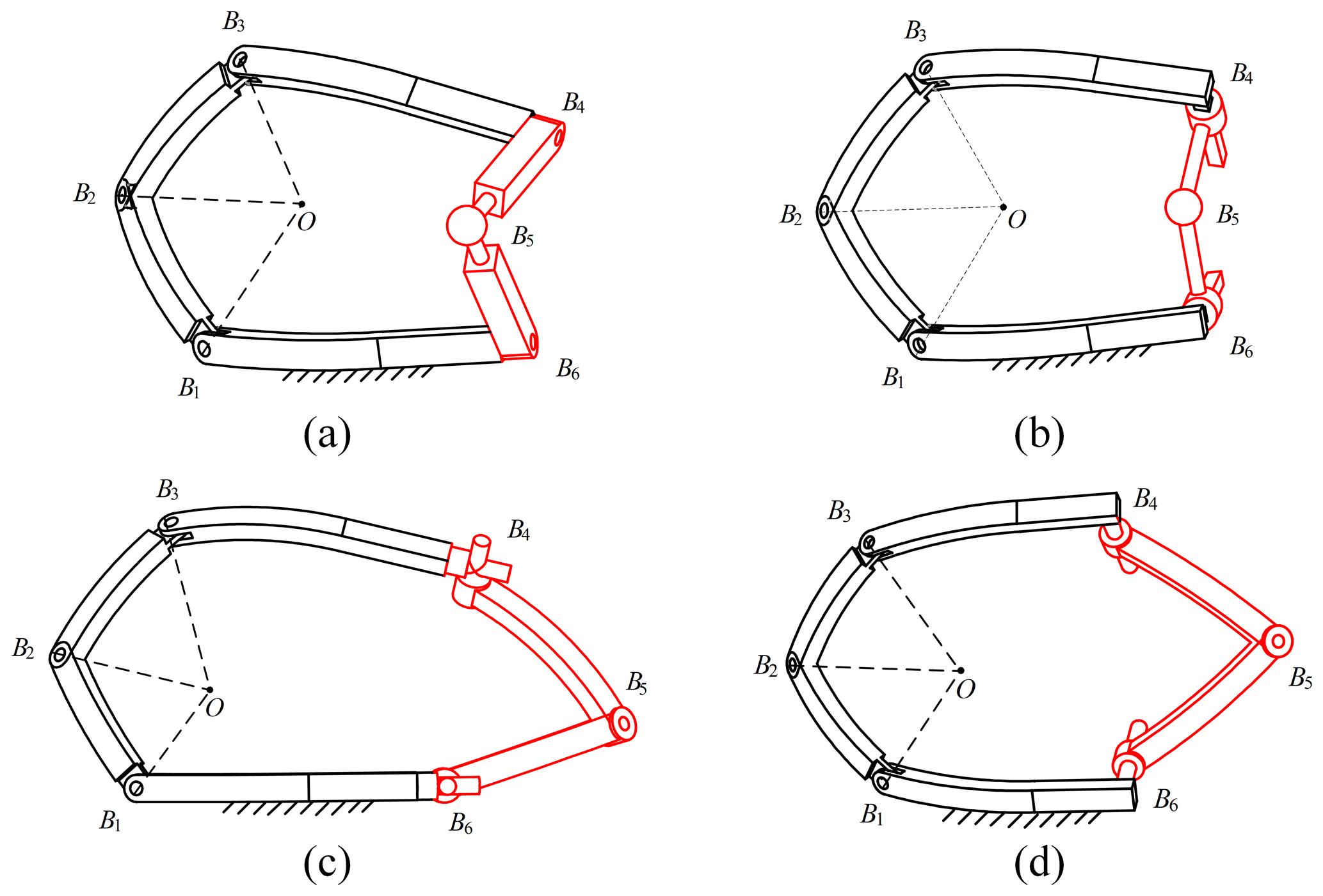
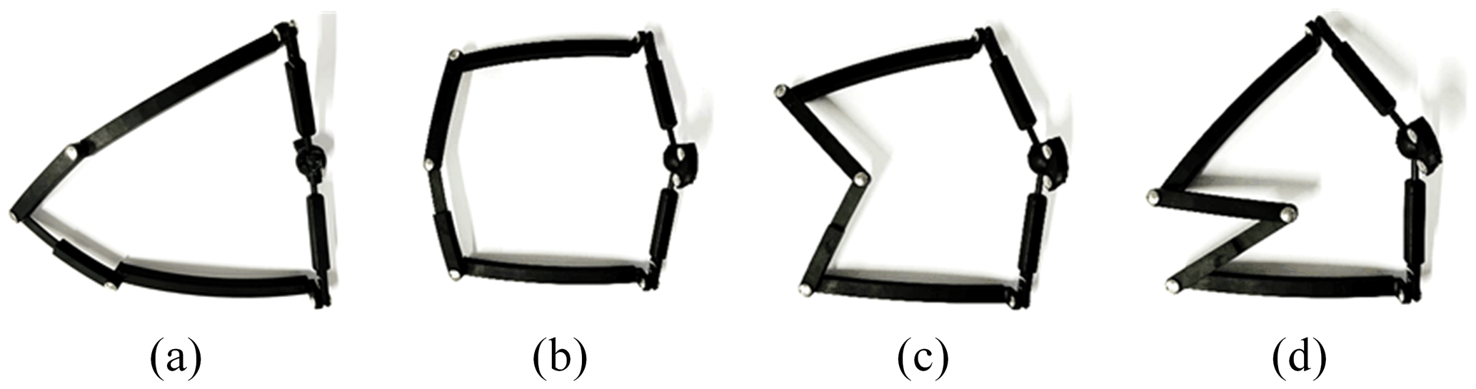
The constraint force through the center of rotation of the spherical joint and the intersection of the axis of rotation is provided by the RSR branch, as shown in Fig. 3a. Since the intersection of the axis of rotation and the RSR branch is symmetric about the center of rotation of the spherical joint at point O, the constraint force can be regarded as the constraint torque perpendicular to the middle plane at point O. Combined with the constraint force provided by the spherical 3R branch, the mechanism has 2 DOFs. Similarly, the PSP branch, URU branch, and CRC branch are shown in Fig. 3b, c, and d, respectively.
3.1 Degree-of-freedom analysis
The symmetric SPM RSR branch (Fig. 3a) is utilized as an example, and the DOF property of the mechanism is analyzed based on screw theory. The coordinate system is established as shown in Fig. 1, where the rotation center O serves as the origin of the coordinate and the positive direction of the x axis is pointed from O to Q (mid-point of the base). The y axis is positively directed from Q to B6 within the plane where the base lies, while the positive direction of the z axis is determined by the right-hand rule, which is perpendicular to the plane of the base.
The SPM is then analyzed in detail. The specific structure of the end actuator shown in Fig. 1 is displayed in Fig. 4. The B3P part is arc-shaped, and PB4 is line-shaped perpendicular to line OP (P is the mid-point of the end effector).
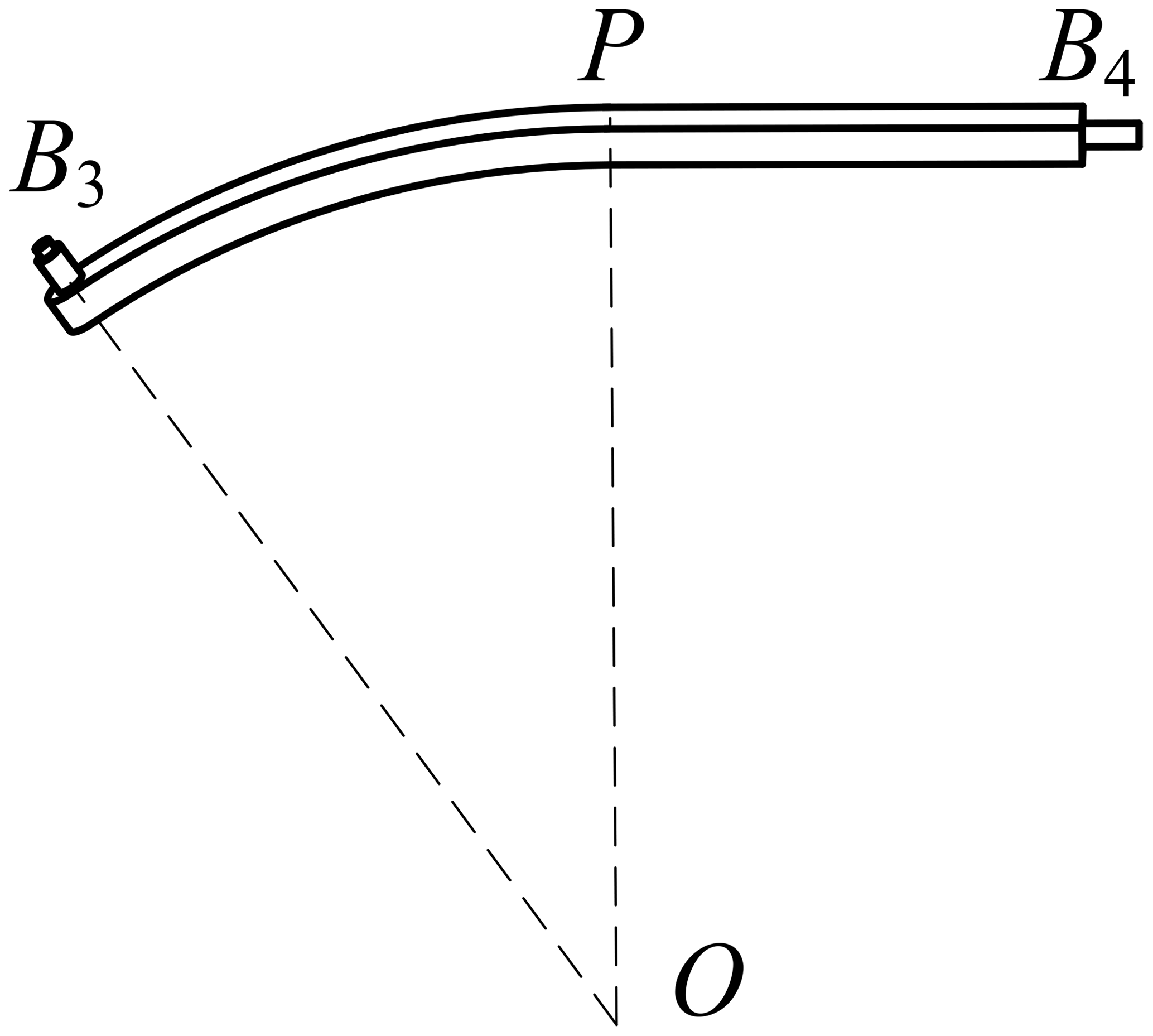
With the exception of the varying radius, the configuration of the base and end effector are nearly identical, leading to a slight disparity in the architecture between rotation joints B6 and B4. However, the overall symmetry of the mechanism remains intact, as points P and Q exhibit symmetrical properties relative to the middle plane.
The constraint screw system of the branch of the spherical 3R branch determined by rotation joints B1, B2, and B3 is the same with Eq. (2). We assume that the coordinates of the center point of each kinematic pair of the constraint force branch are
Respectively, l4, m4, n4 are the direction number of the rotation axis of the rotation pair, B4. The kinematic screw system of the RSR branch formed by the rotation joints, B4 and B6, and the spherical joint, B5, is
where pB4=y4n4, , and .
The constraint screw system of the RSR branch is
where , , n6=z5, and .
It can be found from the direction number and the coordinate of the center point of rotation joint B4 that the equation of the line B4C is
As shown in Fig. 1, we assume that the intersection point of the PB4, and the rotation axis of the rotation joint QB6, is
where xc=x6 and zc = 0, the axis of the rotation joint, B6, is parallel to the y axis and located on the coordinate plane O(x, y). By substituting Eq. (6) into Eq. (5), we obtain
According to Eq. (4) and Eqs. (6), (7), and (8), it can be concluded that
Therefore, the constraint screw of the RSR branch is a constraint force along the direction of line B5C. According to the symmetrical structure of the spherical mechanism, it can be found that the points B5 and C are both on the middle plane of the mechanism. Moreover, the design principle requires that the intersection point of the revolute axes of the rotation joints B4 and B6 in the RSR branch and the rotation center of the spherical joint B5 do not pass through the rotation center O of the mechanism, so the constraint force provided by RSR branch can be equivalent to the constraint torque perpendicular to the middle plane. The rotation of the end effector around the axis perpendicular to the middle plane is limited. Combined with the constraint force provided by the spherical 3R branch, it can be found that the mechanism has 2 DOFs, and its structure remains symmetrical about the middle plane during the moving process.
3.2 The establishment of the coordinate systems
As shown in Fig. 5, the coordinate systems of the symmetrical SPM are established. The global coordinate system O(X0, Y0, Z0) is the same as O(x, y, z) in Fig. 1. The local coordinate system O(Xi, Yi, Zi) attached to the ith link is established, and the structural parameters of the mechanism are expressed based on D–H link parameters. The distance from the rotation center of each rotation joint to the rotation center of the mechanism is denoted byRi (i=1, 2, 3). The angle between the X1 axis and X2 axis is denoted by α2, and the angle between the X2 axis and X3 axis is denoted by α3. The angles between the planes that the adjacent links are lying on are θ21, θ32, θ43, θ54, θ65, and θ61, respectively, and the positive direction is counterclockwise, along the axes of the rotation joints toward the rotation center, O. Due to the characteristics of the spherical mechanism, the rotation center is intersected by the axes of each rotation joint, the length of each link is ai=0 (i=1, 2, 3), and the distance between adjacent links is dij=0 (ij=21, 32, 43). The ith local coordinate systems are also located at the rotation center O. The Xi axis is collinear with the revolute axis of Bi and the position direction points from O to Bi. The Yi axis is located on the plane where the ith link is lying, the positive direction points from O to the side where the link is located, and the zi axis is defined by the right-hand rule. OP coincides with the X4 axis of the local coordinate system on the end effector, the Y4 axis is located in the plane where the end effector is lying on and parallel to the axis of the rotation joint B4, and the Z4 axis is perpendicular to the plane where the end effector is located.

The distance between Q and the revolute center of B6 is denoted by l1, the distance between P and revolute center of B4 is denoted by l4, the distance between the revolute center of B4 and B5 is denoted by l5, and the distance between the revolute center of B5 and B6 is denoted by l6; finally, l1=l4, l2=l3 and l5=l6.
Because the mechanism has 2 DOFs, the configuration can be represented by two angles, φ and γ, where φ is represented by the angle between OP and the X0 axis and γ is represented by the angle between the mid-perpendicular plane of the end effector and the plane O(x0, z0). We designate point P as the output reference point of the mechanism. The driving parameters of the mechanism are θ21 and θ61. In inverse kinematics, the driving parameters θ21 and θ61 can be solved when the configuration parameters φ and γ of the end effector are given.
3.3 Inverse kinematic solutions
When the output parameters φ and γ of the mechanism are known, the driving angle θ21 of the equivalent spherical 2-DOF mechanism can be obtained according to the method of the inverse kinematic solutions introduced in reference (Z. M. Chen et al., 2022). The driving angle, θ61, is obtained by solving the coordinates of the center point of the spherical pair B5 in the base system O(X0, Y0, Z0).
The driving parameters θ21 can be obtained as follows:
When the end effector and the base coincide, the coordinate systems O(X4, Y4, Z4) and O(X0, Y0, Z0) coincide as well, so the transformation matrix between the two links can be expressed as
where ω represents the angle between the plane passing through the lines OP and OQ at the same time and the coordinate plane O.
The coordinates of P and the rotation center of B4 in the local coordinate system, O(X4, Y4, Z4), can be expressed as follows:
The coordinates of P and the rotation center of B4 in the global coordinate system, O(x0, y0, z0), can be obtained from Eq. (11):
The coordinates of the rotation center of B6 in the global coordinate system, O(x0, y0, z0), can be expressed as follows:
The coordinate of the rotation center of spherical joint B5 in the global coordinate system, O(x0, y0, z0), can be obtained by determining the intersection point of two circles. One is determined by a spherical surface, whose radius is l5 and the center is B4, and a plane, which is vertical to vector PB4 and passes through the line B4B5. The other is determined by a spherical surface, whose radius is l6 and the center is B6, and a plane, which is vertical to vector QB6 and passes through the line B5B6. Therefore, the coordinate b50=(x5 y5 z5)T in the global coordinate system, O(x0, y0, z0), can be expressed by the following equation:
where , , and , representing the direction number of line PB4 along the coordinate axes in the global coordinate system.
The driving parameter, θ61, can be derived from the structure of the mechanism and Eq. (15):
The paraments z2 in Eq. (10) and z5 in Eq. (18) both have two solutions, which means that four sets of solutions correspond to one position. The four initial configurations with different arrangements of the driving links (, , , and ) are shown in Fig. 6. The initial configurations in Fig. 6a are selected for the following analysis.
3.4 Forward kinematic solutions
Given the driving parameters θ21 and θ61, the solution of the configuration parameters, φ and γ – that is, the forward kinematic solution of the spherical mechanism – can be figured out. The coordinate of the rotation center of spherical joint B5 in the global coordinate system, O(X0, Y0, Z0), can be expressed with a given value of the driving parameter θ61:
According to a reference (Zhang et al., 2006), the configuration parameters can be obtained as follows:
3.5 Equivalent rotation characteristics of the SPM
The end effector of the 2-DOF SPM has the ability to continuously rotate around the axis passing through the rotation center and lying on the middle plane throughout the entire motion. In addition, this mechanism possesses other noteworthy motion properties. Specifically, starting from the initial position and ending at the target position, the end link can achieve a pose transformation through a fixed-axis rotation, known as the equivalent rotation of the mechanism.
In Fig. 7a, the end effector travels from position I to position II, with middle planes s1 and s2 at the starting and ending points, respectively. Points P1 and P2 are the reflections of Q across the middle plane, and line l represents the intersection between the two middle planes. It is proven below that line l is the axis of equivalent rotation of the mechanism.
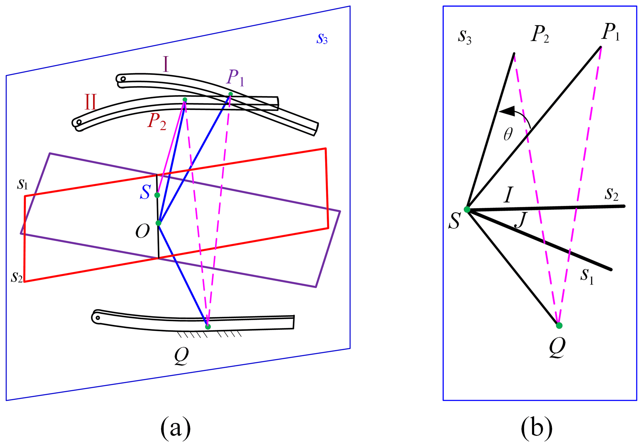
Figure 7Equivalent rotation characteristics of the SPM: (a) schematic diagram of initial and final configuration and (b) equivalent rotation diagram.
Based on the structural characteristics of the mechanism, the fixed link and the end link remain symmetric about the middle plane during the motion process. Thus, we can obtain the following:
To provide a clearer illustration, a plane s3 passing through line OP1 and perpendicular to line l is introduced in Fig. 7b. Point S is the intersection of line l and plane s3, while points I and J correspond to the intersections of line OP1 with plane s1 and line OP2 with plane s2, respectively.
The point Q is on the plane, according to Eq. (19):
That is, if line l is on the plane, and the mechanism remains symmetric during the motion, then
Therefore, point P1 can rotate around line l by a distance of θ to reach point P2, as long as point P is the symmetrical point to point Q about the middle plane. Point Q can be arbitrarily selected on the fixed link, indicating that line l is the equivalent rotational axis of the mechanism.
4.1 Establishment of the complete Jacobian matrix
In the global coordinate system, O(X0, Y0, Z0), the instantaneous motion screw of the end effector link can be denoted as , where ω represents the instantaneous angular velocity of the moving link and vo represents the instantaneous velocity at the point where it is firmly connected to the moving link and coincides with O.
The 3R branch has 3 DOFs; thus, the instantaneous motion screw of the moving link can be represented as a linear combination of the three screws as follows:
where and , respectively, denote the unit motion screw and angular velocity for the ith joint in the RRR branch, with
sBi signifies the unit directional vector along the axis of the ith joint in the RRR branch. B1, B2, and B3 represent the coordinates of their corresponding points expressed in the O(X0, Y0, Z0) coordinate system.
According to screw theory, within the branch, there are three screws that reciprocally commute with all the motion screws in that branch, denoted as . Subsequently, by taking the dot product of both sides of Eq. (24), we obtain
where
In matrix form, this can be expressed as
The RSR branch has 5 DOFs; thus, the instantaneous motion screw of the moving link can be represented as a linear combination of the five screws as follows:
where and , respectively, denote the unit motion screw and angular velocity for the ith joint in the RSR branch, with
sBi represents the unit directional vector along the axis of the ith joint in the RSR branch. B4, B5, and B6 represent the coordinates of their corresponding points expressed in the O(X0, Y0, Z0) coordinate system.
In the same way, we obtain
where
In matrix form, this can be expressed as
The constraint screw of the mechanism is obtained by combining the constraint screws from the two branches:
where represents the constraint Jacobian matrix, .
The drivers of the mechanism are θ21 and θ61; when these drivers are locked, the rank of the constrained screw increases, and the additional constrained screw added by the ith branch is denoted as . By taking the dot product of Eqs. (24) and (27), and , respectively, we obtain
The newly added constrained screw of the 3R branch is denoted as
The newly added constrained screw of the RSR branch is denoted as
Expressing this in matrix form, we have
where
denotes the driving Jacobian matrix and represents the input velocity of the revolute joints.
By combining Eq. (30) and Eq. (32), we obtain
where and .
The J in Eq. (33) represents the comprehensive Jacobian matrix of the mechanism.
4.2 Workspace analysis
Due to mechanical interference, reference point P of the effector cannot reach every point on the spherical surface. As shown in Fig. 8, suppose the width of each link of the mechanism is 8 mm; the effective radius is then R = 200 mm – that is, l1=l4 = 36 mm, l5=l6 = 50 mm, 200 mm, and αi = 30° (i = 1–4).
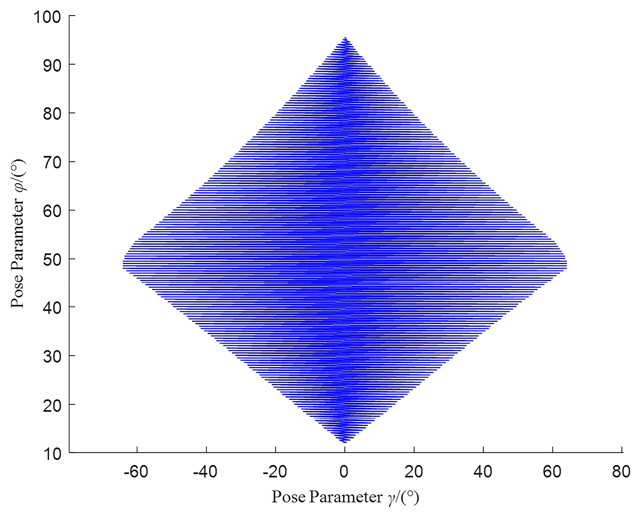
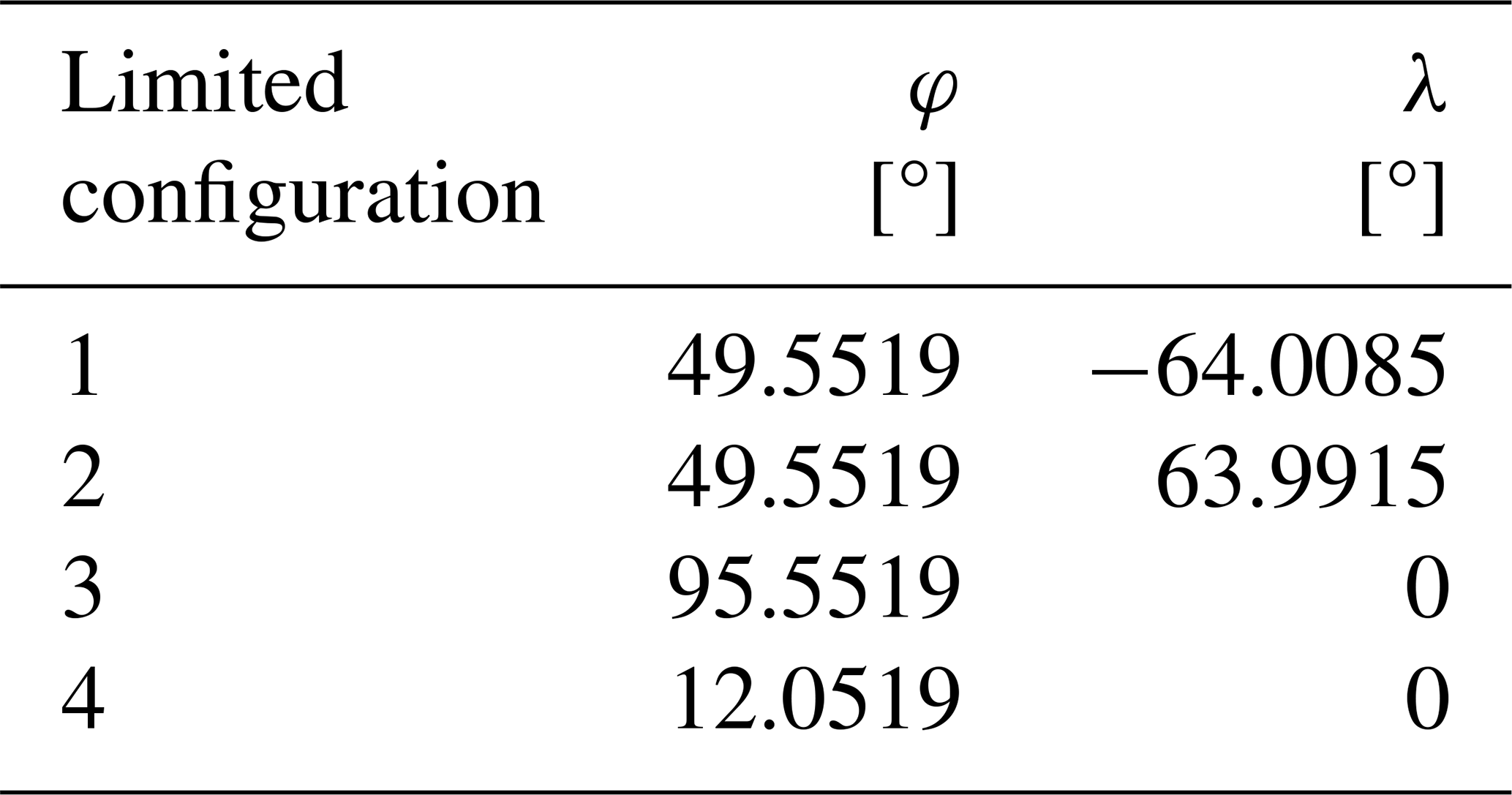
The following conclusion can be drawn from Fig. 8: (1) as the angle φ between OP and the x0 axis varies, the rotational ability of the end link 4 also varies (range of orientation parameter γ). The closer the orientation parameters φ and γ are to their extreme values, the smaller the working space of the mechanism. When the orientation parameters φ and γ are set to their mid-range values, the working space of the mechanism is relatively large. (2) When the end link reaches the left or right extreme position at °, driving links 2 and 6 also reach their respective limit positions. When γ=0°, the end link reaches the upper or lower extreme position at φ=95.8430° and φ=11.5519°; the specific mechanism orientation and corresponding orientation parameters are described in Table 2.
Table 2Limited configuration parameters of the spherical mechanism.
4.3 Dexterity analysis
The dexterity primarily reflects the transmission accuracy of motion between input and output; Salisbury and Craig (1982) proposed using the condition number of the Jacobian matrix of a mechanism as a performance metric for the dexterity of the mechanism. The condition number of its inverse matrix, J−1, is chosen as the performance metric for the dexterity of the mechanism. This metric reflects the ability of the end effector to rotate in a certain direction, and the spectral norm of the matrix is used to compute the condition number.
The matrix norm, ∥A∥, also known as the spectral norm of a matrix, can be redefined in geometric terms as follows:
The condition number of the Jacobian matrix of the institution considered in this paper can be defined as follows:
As defined by Eq. (34), the spectral norm of a matrix can be expressed as follows:
Since JTJ is a positive definite or positive semidefinite matrix, its eigenvalues are non-negative, and we obtain
where λi(JTJ) represents the eigenvalues of matrix JTJ. Thus, the spectral norm of matrix J is represented by the square root of the largest eigenvalue of JTJ, denoted as δmax, while the spectral norm of matrix J−1 is represented by the reciprocal of the square root of the largest eigenvalue of JTJ, denoted as . Therefore, the condition number of the Jacobian matrix J−1 can be expressed as
In accordance with the structural parameters of the mechanism outlined in Sect. 4.2, the dexterity of the 2-DOF SPM presented in this article is expressed in Fig. 9.
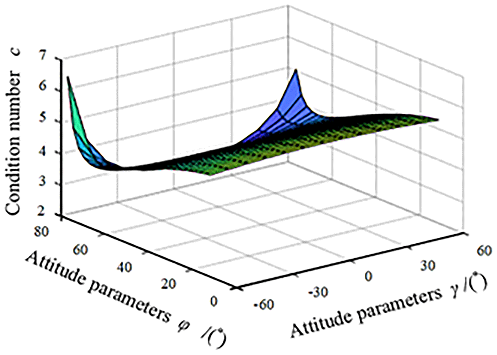
When the condition number is large, the precision of the inverse matrix of the Jacobian matrix is relatively low, leading to significant distortion in the relationship between input and output velocities. Therefore, it is crucial to ensure a low condition number of the Jacobian matrix within the operational range of the mechanism during its design. The condition number of the Jacobian matrix is a value greater than or equal to 1. A condition number of 1 indicates optimal motion transmission performance, while an infinite condition number signifies a singular configuration.
Fang et al. (2014) introduced the dexterity index of the mechanism as , where the index is determined by angle γ and is not influenced by angle α. A higher value of γ indicates a greater dexterity index. Analyzing this index indicates that the mechanism performs optimally within a workspace where γ≥0.7 rad.
According to Fig. 9, it can be observed that the mechanism exhibits better transmission performance when 20° 60°. Hence, in the design of this spherical mechanism, it is recommended to select a structure with a lower condition number for the Jacobian matrix. Figure 9 provides valuable visual insights for the design process.
4.4 Force/torque transfer performance analysis
The condition number of the mechanism Jacobian is used as the analysis index of torque transmission performance, reflecting the driving capacity of the spherical mechanism. The matrix spectral norm is used to calculate the condition number of the Jacobian matrix.
According to the kinematic principles, this can be expressed as , where τ and F are the output and input force vectors, respectively. The Euclidean norm of the output force vector, τ, can be expressed as
According to the properties of matrix norms, we have
where δmin and δmax are solved using a method similar to that in Eq. (34) and can be obtained by taking the square root of the minimum and maximum eigenvalues of matrix J.
The condition number of the Jacobian matrix can be defined as follows:
As the value of Eq. (42), ε, is greater than or equal to 1, for convenience, we describe the local torque transmission performance of the mechanism using the reciprocal of the condition number , as shown in Fig. 10. The value of this parameter varies between 0 and 1, and the structural parameters of the mechanism are the same as those in Sect. 4.3.
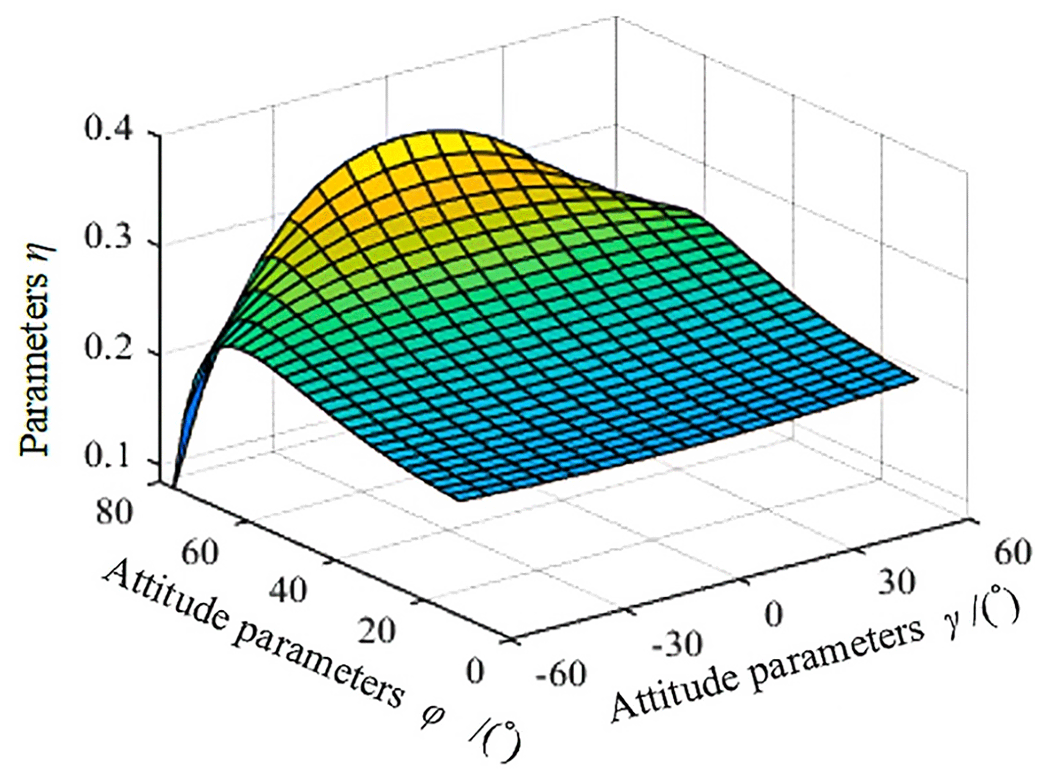
From Fig. 10, we can see that the η parameter changes relatively smoothly within a certain range and that the torque transmission performance of the mechanism is good. However, when the mechanism approaches the edge of the workspace, the parameter changes significantly and the torque transmission performance becomes unstable. Therefore, in the structural design of this spherical mechanism, the actual needs and the analysis of the workspace and torque transmission performance of the mechanism should be combined and compared.
4.5 Verification of the kinematic analysis
After inputting two tiny input variables, θ21 and θ61, the validation of the correctness of Jacobian matrix and forward kinematics was carried out by comparing the numerical solution obtained using Eqs. (32) and (33) with the measurement results obtained using the computer-aided design (CAD) model. The model is verified using four sets of data under different conditions as shown in Table 3. It is assumed that the measured values of the three-dimensional model are accurate and that the relative error in the Jacobian matrix is within 3 %.
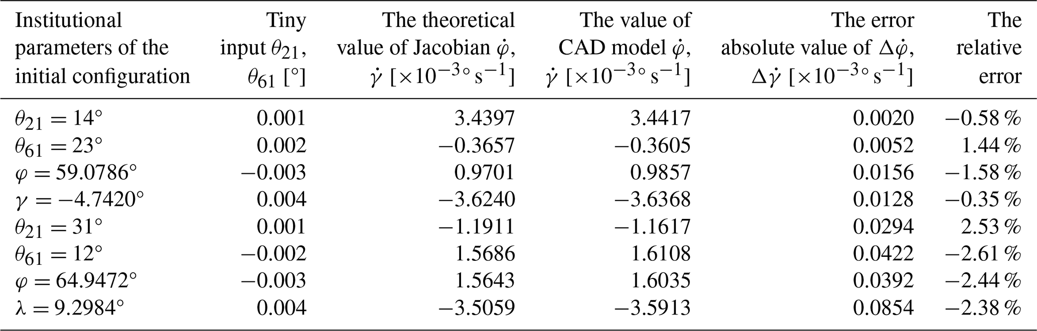
The correctness of the kinematic and velocity analyses of the 2-DOF SPM studied in this paper is verified using this numerical validation method to validate the inverse model of the mechanism.
5.1 Kinematic simulation based on RecurDyn
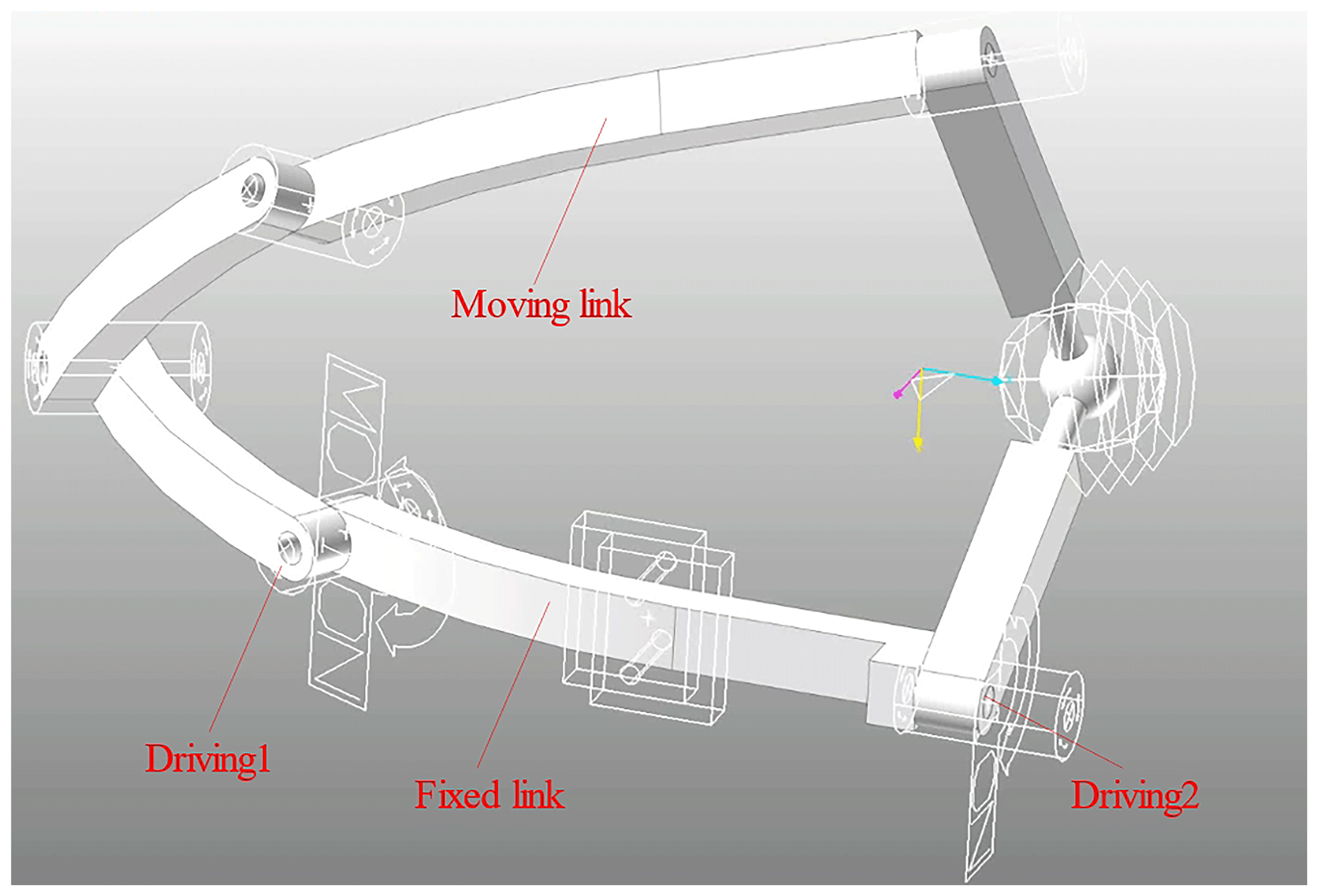
The kinematic simulation verification of the 2-DOF SPM mechanism was conducted using SolidWorks and RecurDyn software. In SolidWorks, the various components of the motion simulator were built and assembled into a three-dimensional model. After simplifying the model, it was imported into the RecurDyn software, where motion pairs and drivers were added to obtain a virtual prototype model, as shown in Fig. 11. During the RecurDyn simulation, the fixed link is kept stationary. Driving 1 is applied at the revolute joint R1 to drive the motion of other linkages, while driving 2 is applied at the revolute joint R6 to drive the motion of other linkages. This results in continuous movement of the end linkage from its initial pose to the final pose, achieving a single equivalent rotation about an axis on the virtual symmetric plane situated along a certain axis.
The mathematical expression for the output motion of the moving link can be represented as follows:
where R1 represents the angular displacement function for the rotational motion of θ21 and R6 represents the angular displacement function for the rotational motion of θ61.
Therefore, the simulation results of the 2-DOF SPM mechanism were obtained. The input angular displacement–time curves for each driving link are shown in Fig. 12, while the driving force–time curves are depicted in Fig. 13. From the figures, it can be observed that the required driving curves for each branch are remarkably smooth, indicating excellent kinematic performance.
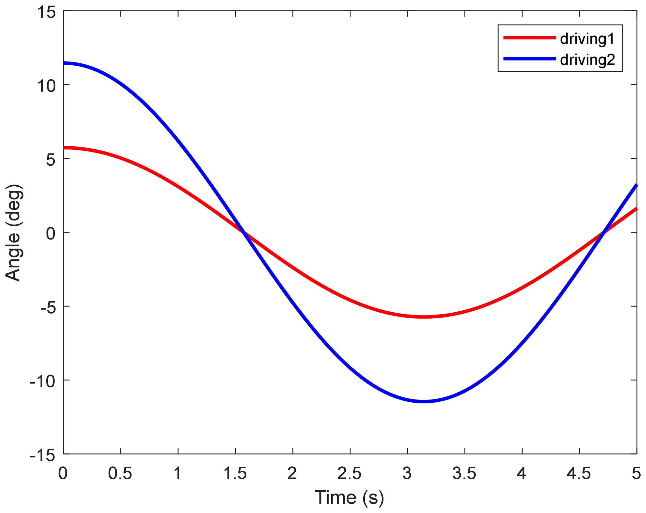
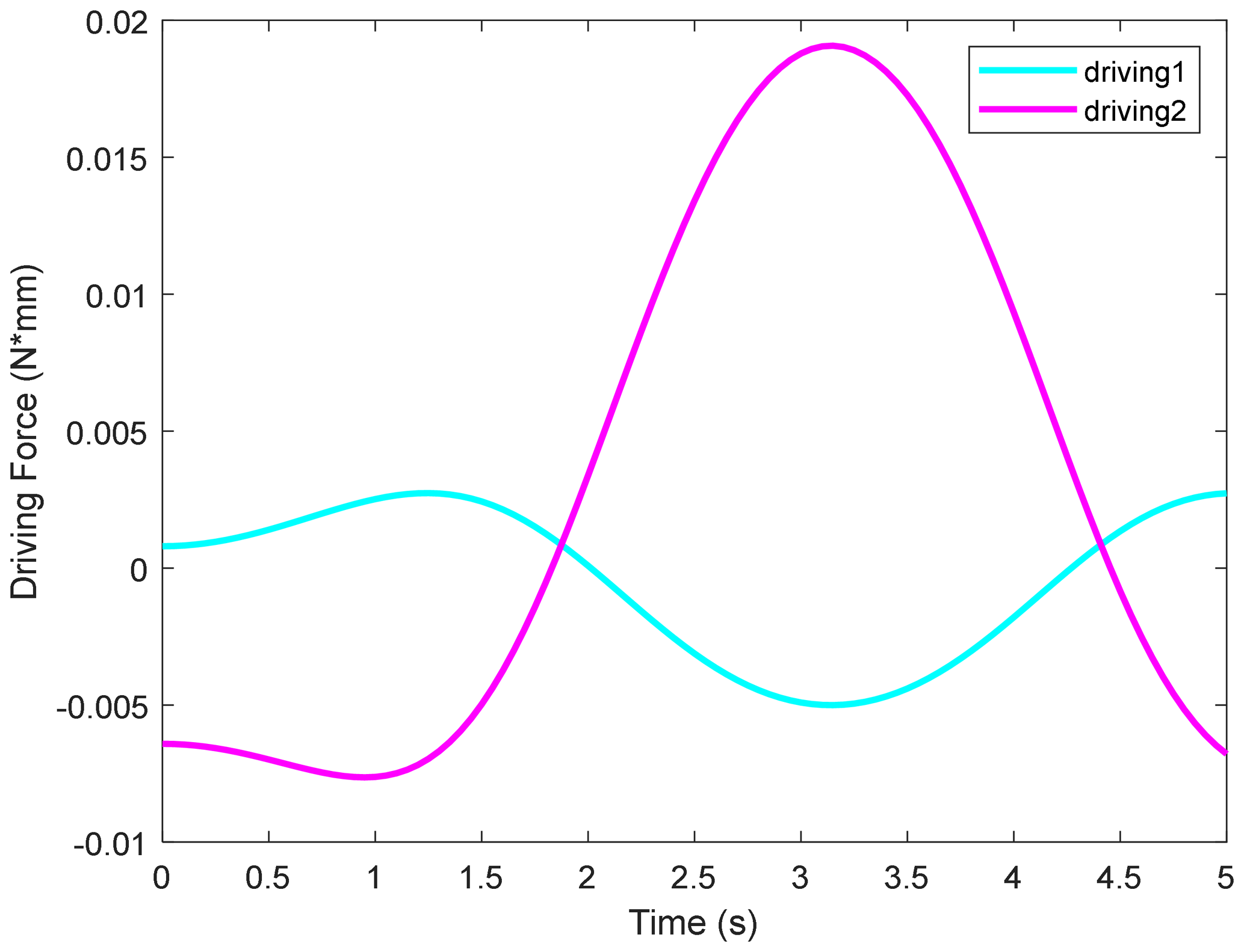
We observed that, when provided with a set of continuously varying driving forces, the motion of the end effector obtained through simulation remains continuous, with no sudden changes in torque occurring during the motion process. This demonstrates the continuity and stability of the mechanism's motion.
5.2 Prototype and experiment
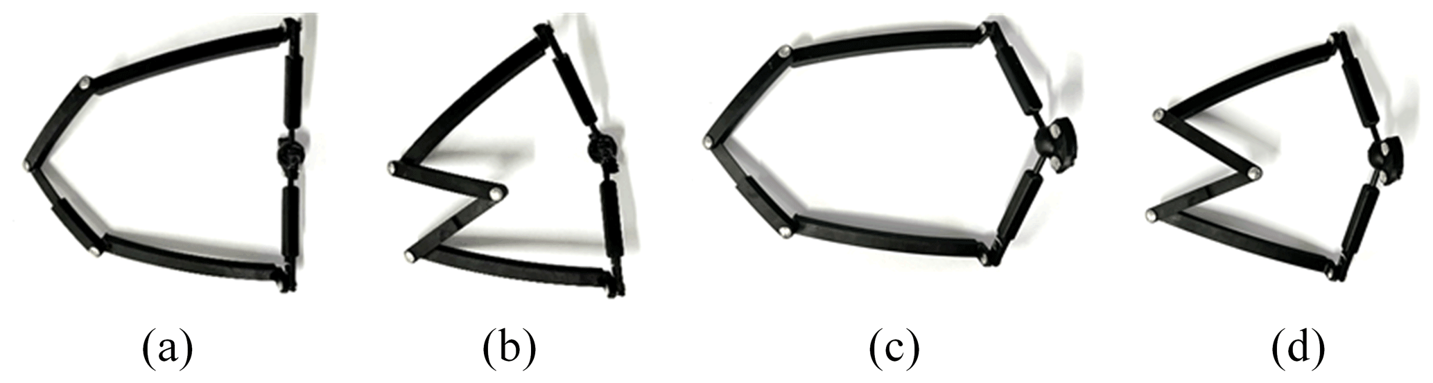
After the kinematic simulation, the kinematic performance of 2-DOF SPM is further verified. In this section, a prototype 2-DOF SPM is built, and its motion capability is verified by experiments. The four initial configurations with different arrangements of the driving links (, , , and ) are shown in Fig. 14. After the mechanism is rotated at a certain angle, the configuration is shown in Fig. 15. The prototype experiment results show that the design and kinematic analysis of the novel 2-DOF SPM are correct and reasonable.
This paper proposes a design principle based on the virtual middle plane constraint method, which integrates the branch constraint of the mechanism into the middle virtual constraint plane. On the one side, two spherical 3R branches symmetrically provide 3 rotational DOFs, while on the other side, a constraint force located on the middle plane restricts one rotational DOF, allowing the end effector to achieve 2-rotational-DOF spherical motion. Specific requirements include (1) ensuring that the angle between the fixed link and the end effector remains constant with respect to the middle plane throughout the motion of the mechanism and symmetrically arranged. (2) The joint axes of the 3R branch on the left intersect at the center of the sphere. (3) The constraint force provided by the right constraint branch is located on the middle plane. Based on these principles, a series of symmetric SPMs is designed. The SPM can realize continuous rotation around any line on the middle plane which passes through the rotation center of the spherical mechanism, and the rotational axis can be fixed during the rotation process, which means that any form of motion of the mechanism can be transformed to a rotation with a fixed axis.
The kinematic solutions of the symmetrical SPM based on the RSR branch are given. The inverse and forward kinematic mechanisms are determined using screw theory. To obtain the inverse Jacobian matrix of the 2-DOF SPM, the constraint equation is differentiated. The workspace of the mechanism is obtained by considering inverse kinematics and link interference conditions. We find that when the orientation parameters φ and γ are closer to the extreme values, the working space of the mechanism is smaller, and when the orientation parameters φ and γ are set to the middle values, the working space of the mechanism is larger. The dexterity and force/torque transfer performance of the mechanism are analyzed within a specific range along with the condition number of the Jacobian matrix. In the design of SPM, it is concluded that structures with lower condition numbers of Jacobian matrices are preferred, while practical requirements and analyzing the mechanism workspace and torque transmission performance are still considered. Through the combined simulation of SolidWorks and RecurDyn, this study successfully verified the excellent kinematic performance of the investigated mechanism. The successful verification confirms that there is no abrupt change in torque during motion, demonstrating the excellent performance of the research institution in motion. The correctness and rationality of the kinematic model are verified by the prototype experiment. These results provide a useful reference for the structural design of the mechanism. The 2-DOF SPM holds significant potential for applications in ankle and shoulder rehabilitation robots. Its unique characteristics, including its compactness and precise motion control, make it particularly suitable for these domains.
In the future, we will continue to carry out research work on 2-DOF SPMs. This will include research into the statics and dynamics of such mechanisms, and further research and development efforts should focus on fully harnessing the potential of this mechanism to advance the field of rehabilitation robots, ultimately benefiting patients in their recovery processes.
All code included in this study is available from the corresponding author on reasonable request.
The data generated during this study are available from the corresponding author on reasonable request.
XC conceived the idea and organized the paper structure. CX and ZZ prepared the figures and wrote this paper. YG and AY developed the simulation models. ZC was the project administrator.
The contact author has declared that none of the authors has any competing interests.
Publisher’s note: Copernicus Publications remains neutral with regard to jurisdictional claims made in the text, published maps, institutional affiliations, or any other geographical representation in this paper. While Copernicus Publications makes every effort to include appropriate place names, the final responsibility lies with the authors.
The authors wish to thank Yanshan University for its support.
This research has been supported by the National Natural Science Foundation of China (grant no. 51775474).
This paper was edited by Med Amine Laribi and reviewed by six anonymous referees.
Arredondo-Soto, M., Cuan-Urquizo, E., Gómez-Espinosa, A., Roman-Flores, A., Urbina Coronado, P. D., and Jimenez-Martinez, M.: The compliant version of the 3-RRR spherical parallel mechanism known as “Agile-Eye”: Kinetostatic analysis and parasitic displacement evaluation, Mech. Mach. Theory, 180, 105160, https://doi.org/10.1016/j.mechmachtheory.2022.105160, 2023.
Cao, W. A., Xu, S. J., Rao K., and Ding T. F.: Kinematic Design of a Novel Two Degree-of-Freedom Parallel Mechanism for Minimally Invasive Surgery, J. Mech. Design, 141, 104501, https://doi.org/10.1115/1.4043583, 2019.
Chablat, D., Michel, G., Bordure, P., Venkateswaran, S., and Jha, R.: Workspace analysis in the design parameter space of a 2-DOF spherical parallel mechanism for a prescribed workspace: Application to the otologic surgery, Mech. Mach. Theory, 157, 104224, https://doi.org/10.1016/j.mechmachtheory.2020.104224, 2021.
Chang, Z., Wang, C. B., Wang G. F., and Gao J. S.: Kinematics Analysis and Scale Synthesis of a Novel Spherical Parallel Mechanism, Mechanical Transmission, 46, 45–51, https://doi.org/10.16578/j.issn.1004.2539.2022.06.007, 2022.
Chen, W. B., Zhang, Y. L., Fu, H., Fan, X., Xiong, C. H., and Liang J. J. Y.: Optimization Design of Prosthetic Shoulder Joint Mechanism Based on 3-RRR Asymmetric Spherical Parallel Mechanism, Chinese Science: Technology Science, 52, 1434–1446, 2022.
Chen, Z. M., Cao, W. A., Ding, H. F., and Huang, Z.: Continuous motion of a novel 3-CRC symmetrical parallel mechanism, P. I. Mech. Eng. C-J. Mec., 230, 392–405, https://doi.org/10.1177/0954406215602282, 2016.
Chen, Z. M., Chen, X. C., Gao, M., Zhao, C., Zhao, K., and Li, Y. W.: Motion Characteristics Analysis of a Novel Spherical Two-degree-of-freedom Parallel Mechanism, Chin. J. Mech. Eng., 35, 29, https://doi.org/10.1186/s10033-022-00702-7, 2022.
Dong, X., Yu, J. J., Chen, B., and Zong, G. H.: Geometric approach for kinematic analysis of a class of 2-DOF rotational parallel manipulators, Chin. J. Mech. Eng., 25, 241–247, https://doi.org/10.3901/CJME.2012.02.241, 2012.
Enferadi, J. and Nikrooz, R.: The Performance Indices Optimization of a Symmetrical Fully Spherical Parallel Mechanism for Dimensional Synthesis, J. Intell. Robot. Syst., 90, 305–321, https://doi.org/10.1007/s10846-017-0675-6, 2018.
Fang, S. L., Wang, L., and Ding, S.: Kinematics and performance analysis of fixed hydraulic spherical joint of rudder blade, Journal of Beijing University of Aeronautics and Astronautics, 40, 1563–1567, https://doi.org/10.13700/j.bh.1001-5965.2013.0727, 2014.
Gosselin, C. and Hamel, J.: The agile eye: a high-performance three-degree-of-freedom camera-orienting device, Proceedings of the 1994 IEEE International Conference on Robotics and Automation, San Diego, CA, USA, 8–13 May 1994, IEEE, 781–786, https://doi.org/10.1109/ROBOT.1994.351393, 1994.
Hu, X. and Liu, H.: Design and analysis of full-configuration decoupled actuating reconfigurable parallel spherical joint, J. Mech. Sci. Technol., 36, 933–945, https://doi.org/10.1007/s12206-022-0140-8, 2022.
Kim, T. U. and Oh, Y. H.: Design of spatial adaptive fingered gripper using spherical five-bar mechanism, Proceedings of the 2014 International Conference on Advanced Mechatronic Systems, Kumamoto, Japan, 10–12 August 2014, IEEE, 145–150, https://doi.org/10.1109/ICAMechS.2014.6911640, 2014.
Kumar, S., Bongardt, B., Simnofske, M., and Kirchner, F: Design and Kinematic Analysis of the Novel Almost Spherical Parallel Mechanism Active Ankle, J. Intell. Robot. Syst., 94, 303–325, https://doi.org/10.1007/s10846-018-0792-x, 2017.
Li, T. M. and Payandeh, S.: Design of spherical parallel mechanisms for application to laparoscopic surgery, Robotica, 20, 133–138, https://doi.org/10.1017/S0263574701003873, 2002.
Li, X., Qu, H., and Guo, S.: Kinematic Performance and Static Analysis of a Two-Degree-of-Freedom 3-RPS/US Parallel Manipulator With Two Passive Limbs, J. Mech. Robot., 15, 021014, https://doi.org/10.1115/1.4054767, 2022.
Liu, X. J., Wang, J. S., Gao, F., and Jin, Z. L.: Design of a Serial-Parallel 7-DOF Redundant Anthropomorphic Arm, China Mechanical Engineering, 13, 101–104, https://doi.org/10.3321/j.issn:1004-132X.2002.02.004, 2002.
Luo, J., Liu, H. L., Yu, S. B., Xie, S. R., and Li, H. Y.: Development of an image-based visual servoing for moving target tracking based on bionic spherical parallel mechanism, 2014 IEEE International Conference on Robotics and Biomimetics (ROBIO 2014), Bali, Indonesia, 5–10 December 2014, IEEE, 1633–1638, https://doi.org/10.1109/ROBIO.2014.7090568, 2014.
Naoto, S., Kenjiro, T., Masahiro, W., Eri, T., Masashi, N., Shintaro, S., Masashi, K., and Satoshi, T.: 2-DOF Spherical Parallel Mechanism Capable of Biaxial Swing Motion with Active Arc Sliders, IEEE Robotics and Automation Letters, 6, 4680–4687, https://doi.org/10.1109/LRA.2021.3064187, 2021.
Saafi, H., Laribi, M. A., and Zeghloul, S.: Forward kinematic model improvement of a spherical parallel manipulator using an extra sensor, Mech. Mach. Theory, 91, 102–119, https://doi.org/10.1016/j.mechmachtheory.2015.04.006, 2015.
Saafi, H., Zeghloul, S., Arslcault, M., and Laribi, M. A.: On the Development of a New Master Device Used for Medical Tasks, J. Mech. Robot., 10, 044501, https://doi.org/10.1115/1.4039590, 2018.
Saiki, N., Tadakuma, K., Watanabe, M., Takane, E., Nobutoki, M., Suzuki, S., Konyo, M., and Tadokoro, S.: 2-DOF Spherical Parallel Mechanism Capable of Biaxial Swing Motion with Active Arc Sliders, IEEE Robotics and Automation Letters, 6, 4680-4687, https://doi.org/10.1109/LRA.2021.3064187, 2021.
Salisbury, J. K. and Craig, J. J.: Articulated Hands: Force Control and Kinematic Issues, Int. J. Robot. Res., 1, 4–17, https://doi.org/10.1177/027836498200100102, 1982.
Yu, J. J., Wu, K., Zong, G. H., and Kong, X. W.: A Comparative Study on Motion Characteristics of Three Two-Degree-of-Freedom Pointing Mechanisms, J. Mech. Robot., 8, 021027, https://doi.org/10.1115/1.4032403, 2016.
Yu, S., Zhang, J., Li, W., and Yang, X.: New Decoupled 2-Dof Parallel Mechanism with Fully Spherical Workspace, J. Phys. Conf. Ser., 1575, 012104, https://doi.org/10.1088/1742-6596/1575/1/012104, 2020.
Zhang, L. J., Niu, Y. W., and Huang, Z.: Analysis of the Workspace of Spherical 2-DOF Parallel Manipulator with Actuation Redundancy, in: 2006 International Conference on Mechatronics and Automation, Luoyang, China, 25–28 June 2006, IEEE, 153–158, https://doi.org/10.1109/ICMA.2006.257469, 2006.
Zhang, Y. J.: Design and Research of Launch Platform for Decoupled 3-RRR Spherical Mechanism, MS thesis, Nanjing University of Science and Technology, Nanjing, 72 pp., 2016.
Zhao, H., Gao, F., Zhang, J., and Peng, B.: Statics analysis of a New five-degree-of-freedom parallel mechanism, Mechanical Design, 6, 54–57, https://doi.org/10.13841/j.cnki.jxsj.2004.06.019, 2004.
Zhou, C. C. and Ge, D. J.: Design and Analsis of Spherically redundant mechanism for flight simulator, Mechanical Science and Technology for Aerospace Engineering, 36, 1–5, https://doi.org/10.13433/j.cnki.1003-8728.2017.0924, 2017.
- Abstract
- Introduction
- Analysis of the design principle and structure design of the symmetric SPM
- Kinematic analysis of symmetric SPM
- Performance analysis of the symmetric SPM
- Kinematic simulation and prototype experiment
- Conclusion
- Code availability
- Data availability
- Author contributions
- Competing interests
- Disclaimer
- Acknowledgements
- Financial support
- Review statement
- References