the Creative Commons Attribution 4.0 License.
the Creative Commons Attribution 4.0 License.
 | 26 Apr 2024
Optimal design and experiments of a novel bobbin thread-hooking mechanism with RRSC (revolute–revolute–spherical–cylindrical) spatial four-bar linkage
Bingliang Ye
Xu Wang
Mingfeng Zheng
Pengbo Ye
Weiwei Hong
To solve the problem of low supply of bobbin thread and frequent bobbin changes existing in current embroidery machines, a novel bobbin thread-hooking mechanism with an RRSC (revolute–revolute–spherical–cylindrical) spatial four-bar linkage is proposed which can achieve a large number and continuous supply of bobbin thread. Based on the analysis of the chain stitch formation principle, the design requirements for motion trajectory and posture of the hooking mechanism are proposed. The methods of direction cosine matrix and mechanism identity condition are applied in kinematics modeling and analysis of the RRSC mechanism. The optimization design model and computer-aided software are developed, then the human–computer interaction optimization method is used to obtain optimal solutions to meet working requirements. The physical prototype is machined and a test bench is built. The virtual simulation and prototype high-speed camera kinematics tests are conducted. The results verify the correctness of mechanism design and show good application feasibility of the mechanism.
- Article
(4506 KB) - Full-text XML
- BibTeX
- EndNote


China is the world's top producer of embroidery machines, accounting for about 85 % of the total market production. Currently, embroidery machines usually form a lock stitch to realize embroidery work through the matching between the bobbin thread-hooking mechanism and a straight needle with the facial suture (Wang et al., 2019; Zhou and Jiang, 2018). The thread-hooking mechanism, commonly adopting a rotary shuttle device to supply the bobbin thread, is one of the core working parts of the embroidery machine. However, the inner chamber of the rotary shuttle is so small that the amount of bobbin thread stored in the chamber is small. The rotary shuttle must stop frequently for replacing the bobbin, which greatly affects the production efficiency. Therefore, there is great scientific significance and application value to study the stitch formation principle of embroidery work and the thread-hooking mechanism which can meet the large supply of bobbin threads.
At present, a lot of beneficial research has been conducted worldwide on automatic bobbin exchange devices and the innovative design of the thread-hooking mechanism, meeting the large supply of bobbin thread. Essentially, the automatic bobbin exchange device is to use manipulators to replace the empty bobbin with a full one by simulating the process of manually exchanging the bobbin during machine stopping. Hu et al. (2015) in China designed an automatic bobbin thread replacement system based on CAN-BUS (Controller Area Network-BUS), which improved the expandability and flexibility of the system, but the efficiency improvement was limited. Yi et al. (2014) proposed another bobbin replacement mechanism which was applicable to the automatic production line of container bags, which used two manipulators to grasp empty and spare bobbins respectively, with a simple and reliable structure, but the application scenario is single. Haruhiko (2017) invented an automatic bobbin exchanging device, which was guided by a guide rail to complete the exchanging work, improving the compactness of the structure and the convenience of inspection and maintenance, but the improvement of the exchanging rate is limited. Philippe Mall and Kinoshita proposed a box-magazine-type automatic bobbin exchanging device with a compact structure that can accommodate eight bobbins for replacing but only for thick bobbin thread and non-overlapping embroidered stitches (Jana, 2018). The new thread-hooking mechanism is proposed by designing a new stitch to replace the traditional lock stitch, which can achieve the goal of large bobbin thread supply and less downtime, and this could finally improve production efficiency. Jared and Brain (2018) proposed a bobbin-less sewing machine and a stitch weaving method to complete the stitch, including two mechanisms of a loop punching mechanism and a knot picking linkage. But the stitch application scenario is limited and it is difficult to be applied at high speed. Templeton (2018) developed a high-speed bobbin sewing system that eliminates the bobbin and transfers the bobbin thread through a conduit and uses a rotary bearing structure to achieve high-speed operation; however, the effect of the tube transfer of the bobbin thread has not yet been verified in practice.
In conclusion, the principle of automatic bobbin exchange technology is relatively simple and reliable, but it cannot fundamentally solve the problems of interruption of thread traces and time loss caused by many stoppages. It is now the research trend to carry out thread-hooking mechanism innovation to achieve a large amount of bobbin thread. Therefore, in this study, because of the characteristics of the chain stitch compared with the lock stitch, such as high sewing speed, no downtime for thread change and suitable for embroidery of elastic fabric, etc., the chain stitch formation principle is analyzed, and a new bobbin thread-hooking mechanism with spatial four-bar linkage to form a chain stitch is proposed. Then the kinematics modeling and analysis, optimization design, simulation verification and prototype performance testing of the thread-hooking mechanism are carried out.
2.1 Analysis of movement trajectory of the looper
The law of chain stitch formation is an important basis for the design and optimization of the thread-hooking mechanisms. The study firstly analyzes the process of forming a double-line chain stitch by the mechanism looper with the straight needle of a facial suture (shown in Fig. 1) and proposes the requirements of the movement trajectory of the mechanism looper. The chain stitch formation process includes three steps. First, straight needle 5 with facial suture 3 moves downward to pierce into fabric 1 and reaches the lowest point shown in Fig. 1a; then it moves upward to form a facial suture loop with fabric 1, and looper 4 penetrates the loop and hooks shown in Fig. 1b. Second, while the straight needle moves upward, the fabric advances one stitch and the looper moves backward to reach the back of straight needle 5 (as shown in Fig. 1c). Meanwhile the straight needle descends through the fabric for the second time and further down through the triangular loop formed by the looper, the facial suture, and the bobbin thread (as shown in Fig. 1d). Third, the straight needle continues to move upward, forming the loop again, and the looper surrounds the straight needle and penetrates the loop reciprocally again (as shown in Fig. 1e), while pulling the previous stitch tightly and so on and so forth to form a continuous chain stitch (Wu, 1991).
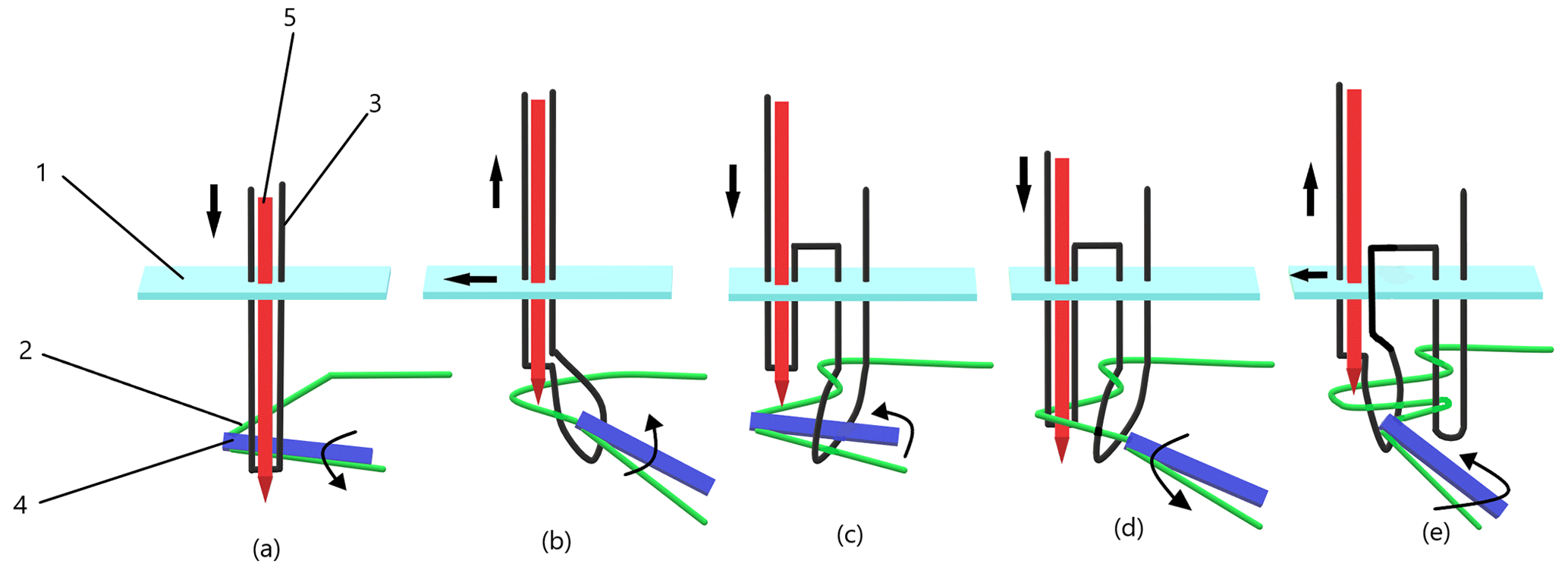
Figure 1Schematic diagram of chain stitch formation process. 1: fabric, 2: bobbin thread, 3: facial suture, 4: looper, and 5: straight needle.
From the analysis of the chain stitch formation principle, it can be seen that the looper tip forms an approximate spatial- elliptical trajectory shown in Fig. 2, in which S is the backwards and forwards spatial displacement of the looper tip, θ is the angular displacement of the looper oscillating around the central axis of the output bar, and L is the linear distance of the looper oscillating between the two limit positions.
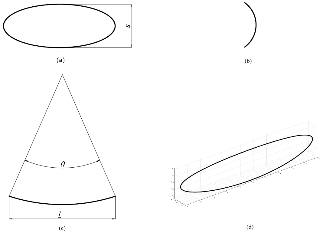
Figure 2Schematic diagram of looper movement trajectory of the thread-hooking mechanism. (a) Main view; (b) left view; (c) top view; (d) three-dimensional view.
2.2 Working principle of the bobbin thread-hooking mechanism with spatial four-bar linkage
According to the movement characteristics of the thread-hooking mechanism looper, a new type bobbin thread-hooking mechanism with RRSC (revolute–revolute–spherical–cylindrical) spatial four-bar linkage is proposed which is composed of crank 0, linkage 1, rocker 2 (fixed with looper 4), and frame 3. In the mechanism, the kinematic pairs between rocker 2 and the frame and linkage 1 are cylindrical pair and spherical pairs, respectively, and those between crank 0 and the frame and linkage 1 are both rotary pairs (as shown in Fig. 3). While the mechanism works, crank 0 is driven to rotate by the power input shaft, and it then drives linkage 1 for spatial compound motion to drive rocker 2. Finally, rocker 2 not only does the oscillation motion but also the reciprocation motion along the vertical direction shown in Fig. 2. By optimizing the parameters of the thread-hooking mechanism, under the combined action of these two movements, the tip of looper 4 fixed on rocker 2 can form a motion trajectory that meets the embroidery chain stitch.
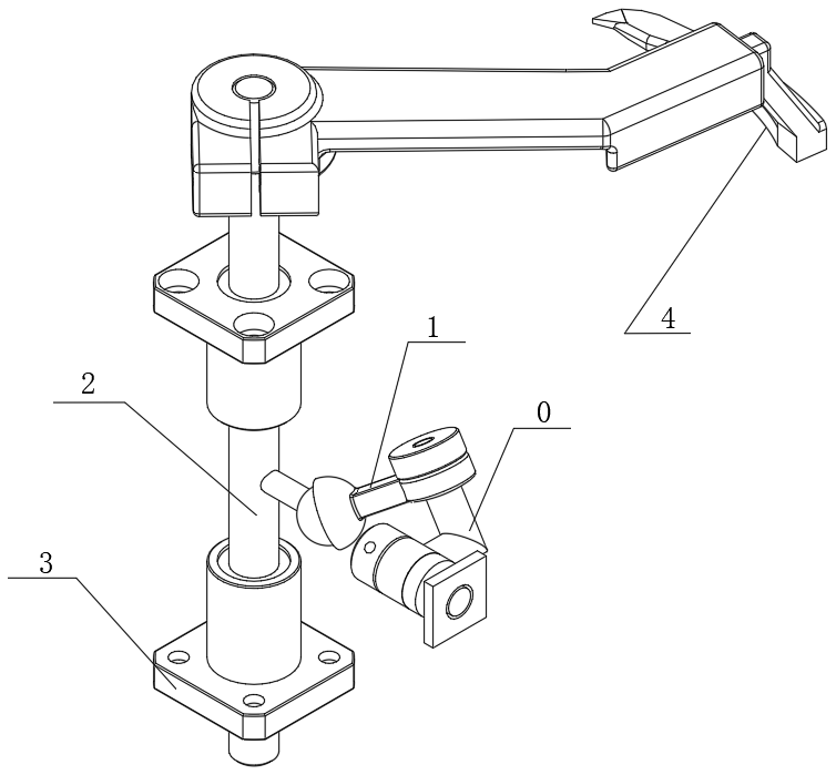
Figure 3Structure diagram of the thread-hooking mechanism with RRSC spatial four-bar linkage. 0: crank, 1: linkage, 2: rocker, 3: frame, and 4: looper.
In order to realize optimal design of the thread-hooking mechanism, its kinematics model is established by using the direction cosine matrix method and the mechanism identity condition. As shown in Fig. 4, rectangular coordinate systems are established on each member of the RRSC spatial four-bar linkage mechanism, and the relative angular displacement and motion between each member are displayed too. The coordinate systems of two adjacent members are set as Oixiyizi and Ojxjyjzj, where i and j both equal to 0, 1, 2, and 3. Crank 0 rotates clockwise, and the motion trajectory of the looper tip P is formed under the synthetic motion of axial movement motion and radial oscillation motion of rocker 2. Therefore, the oscillation angular displacement θ3 and movement displacement S2 of rocker 2 is solved, and the displacement equations of the looper tip P is established (Liu et al., 2019; Vo et al., 2022; Rodríguez-González et al., 2020; Bai et al., 2021; Mohan and Corves, 2017).
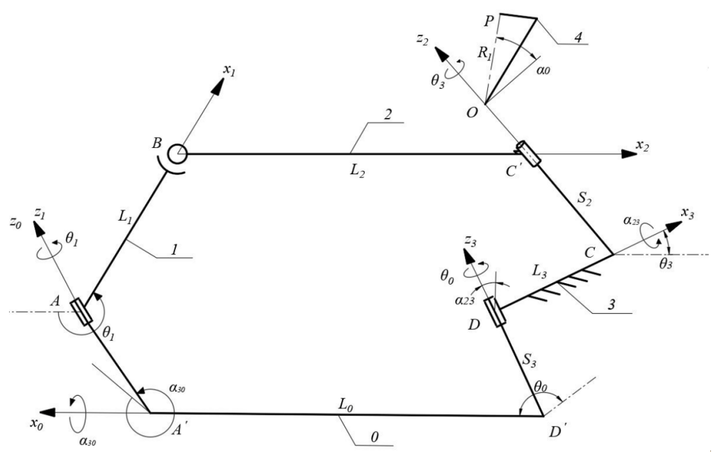
Figure 4Diagram of the thread-hooking mechanism with RRSC spatial four-bar linkage. 0: crank, 1: linkage, 2: rocker, 3: frame, and 4: looper.
3.1 Axial movement displacement of the rocker
The spatial mechanism displacement is analyzed, and the coordinate systems are transformed by the direction cosine matrices (1), (2), and (3) (Zhang, 1984; Li et al., 2019).
The vector closed form of the mechanism is projected onto axis z2, and expanded by the direction cosine matrix to obtain S2.
where
where α0 is initial installation angle of the looper, S0 is distance measured from axis x0 to x1 along axis z0, S2 is distance measured from axis x2 to x3 along axis z2, S3 is distance measured from axis x3 to x0 along axis z3, θ0 is the angle of rotation around axis z0 measured from axis x0 to x1, θ1 is the angle of rotation around axis z1 measured from axis x1 to x2, θ3 is the angle of rotation around axis z3 measured from axis x3 to x0, L1 is the distance measured from axis z1 to x2 along axis x1, α23 is the angle of rotation around axis x3 measured from axis z2 to z3, and α30 is the angle of rotation around axis x0 measured from axis z3 to z0. In the study, it is specified that the abovementioned distances along the coordinate axis in a positive consistent direction are positive, and the angles of rotation in the counterclockwise direction are positive.
3.2 Radial oscillation angular displacement of the rocker
According to the mechanism identity condition, the rocker is split into a linkage chain and a floating chain; subsequently, the intermediate variables are eliminated to obtain the following equation (Zhang, 1985).
Taking A′x0(y0)z0 as the reference coordinate system, the coordinates of points B and C are the following.
By substituting the coordinates of points B and C into Eq. (5), the following equation can be obtained.
By substituting Eq. (4) into Eq. (8), the following equation can be obtained.
where
where L0 is the distance measured from axis z3 to z0 along axis x0, L2 is the distance measured from axis x1 to z2 along axis x2, and L3 id the distance measured from axis z3 to x3 along axis z2.
Set , where , then Eq. (9) can be transformed into the quadratic algebraic equation
where
θ1 is obtained by using Ferrari's method to solve Eq. (10), and then substituted into Eq. (4) to obtain S2 (Chen et al., 2022). The vector closed form of the mechanism is projected onto axis x3 and axis z3, respectively, the relational expression of cos θ3 and sin θ3 is obtained, and finally θ3 can be obtained as the following:
3.3 Displacement equation of looper tip
Set C as the original point, then the axis z coincides with the axis z2z2, and axis x coincides with axis x2; the spatial rectangular coordinate system is established. The spatial displacement equations of tip P of the looper is the following.
where R1 is the vertical distance from tip P of the looper to the cylindrical sub-axis.
By using the direction cosine matrix method, a concise and accurate kinematic model of the spatial mechanism can be established. At the same time, the mechanism identity condition is used to avoid the elimination calculation of some intermediate variables, improve computational efficiency, and ultimately obtain the spatial displacement equations of tip P.
4.1 Optimization objectives and design variables
The tip P of looper of the thread-hooking mechanism forms the spatial elliptical trajectory without motion interference shown in Fig. 2d, the following optimization objectives must be considered for optimizing the parameters of the thread-hooking mechanism.
- 1.
The backwards and forwards spatial displacement of the looper tip S is about 4.5 mm.
- 2.
The angular displacement of the looper oscillating around the central axis of the output bar θ is about 15°.
- 3.
The linear distance of the looper oscillating between the two limit positions, L, is about 20 mm.
Where
According to the kinematics analysis of the thread-hooking mechanism, it is known that α0 only decides the spatial position of the trajectory of the looper tip, and R1 only affects the value of L. Therefore, the mechanism parameters α23, α30, L0, L1, L2, L3, S0, S3 and R1 affecting the shape of the trajectory are taken as the design variables.
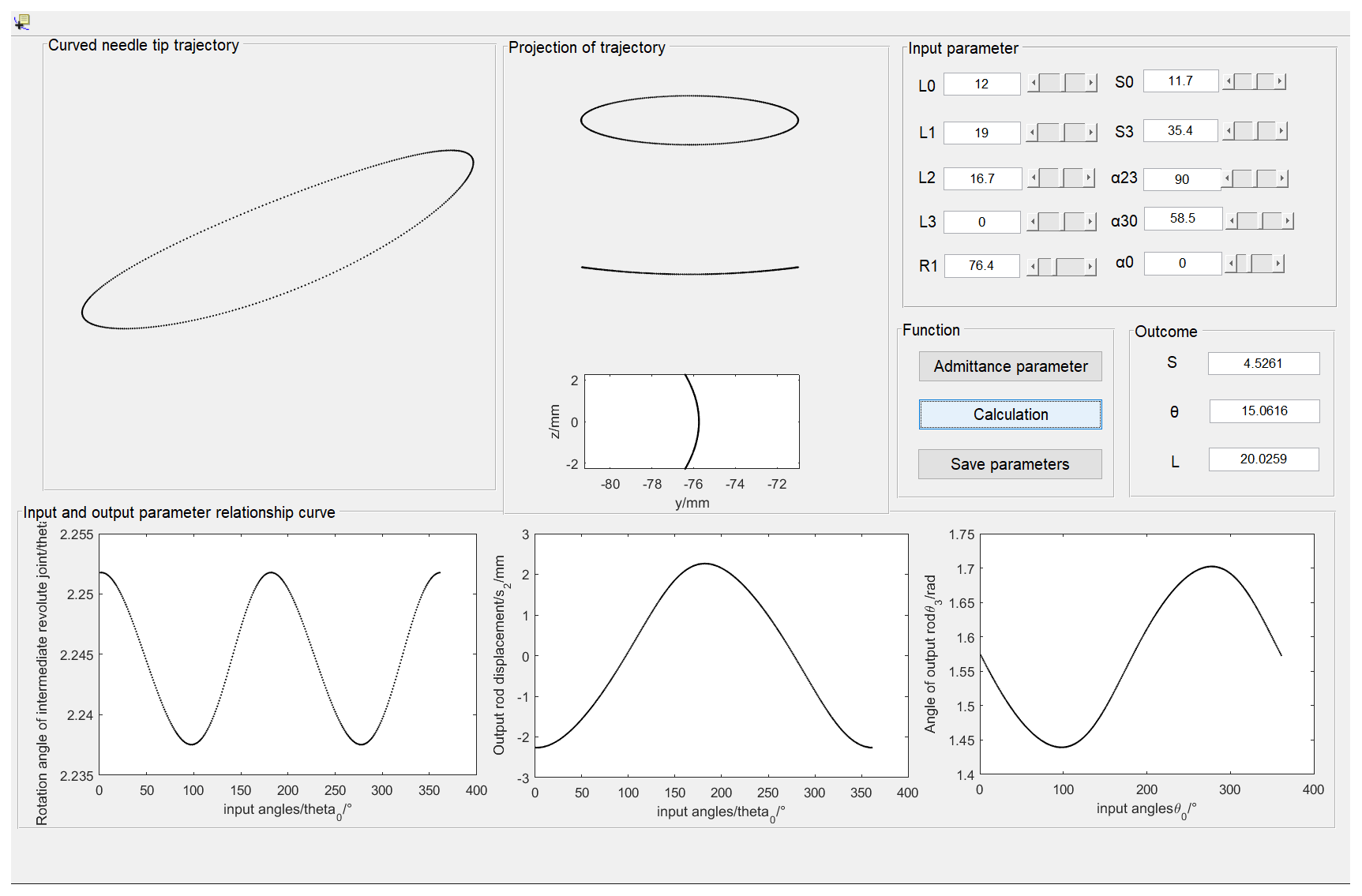
4.2 Optimization software development and parameter analysis of the mechanism
In order to realize parameter optimization of the thread-hooking mechanism with RRSC spatial four-bar linkage, the MATLAB-based computer-aided analysis and optimization software of the mechanism is developed. Figure 5 shows the mechanism simulation and analysis interface. By using this software, the design variables can be input and adjusted through the human–computer interaction method, and the influence law of each design variable on the trajectory of the looper tip can be analyzed. The specific process is as follows: selecting a set of parameters based on experience and entering parameters into the human–computer interaction software to determine whether the optimization goals have been achieved. During the adjustment process, gradually find out which parameters have significant effects on the optimization goals and which parameters have only small effects. The significant effect parameters will improve gradually firstly to find out the optimal solution and then improve the small effect parameters. Finally, after multiple rounds of comprehensive debugging, a set of optimal parameter values will be found (Ye et al., 2011, 2013).
In order to adjust parameters of the thread-hooking mechanism through human–machine interaction conveniently to obtain a set of preferable mechanism parameters, the control variable method is used: one of the parameters is used as an input variable and the rest of the parameters are used as constants to analyze the influence law of this input variable on the trajectory of the looper tip. The comparisons of the trajectory after the change of the value of each parameter of the mechanism are shown in Fig. 6.
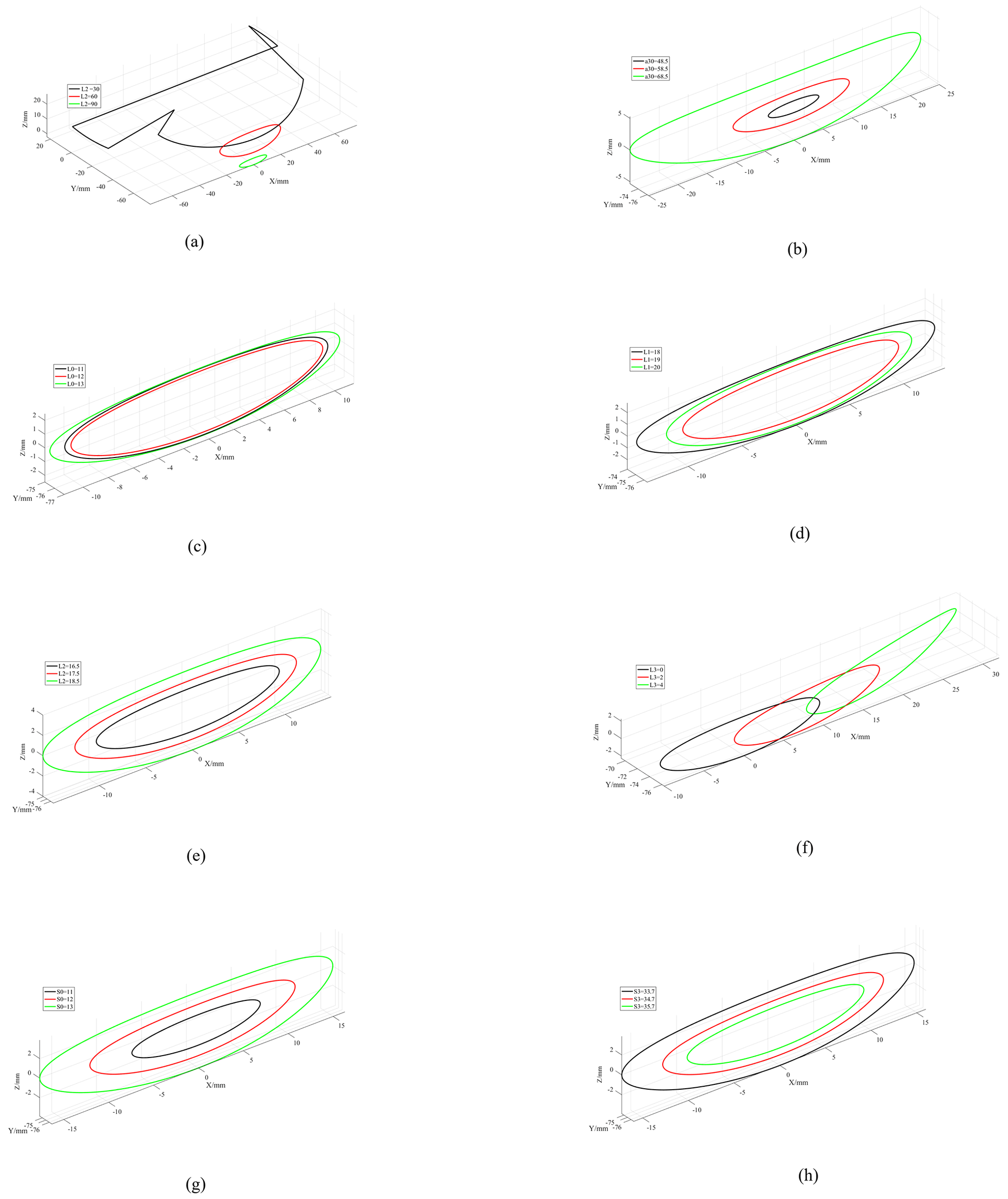
As shown in Fig. 6a, a23 has an obvious influence on the trajectory. While a23 is equal to 30°, it is unable to form a motion trajectory, and while the value is 90° the trajectory meets the requirements. As shown in Fig. 6b, α30 is positively correlated with the trajectory shape and influences it significantly. As shown in Fig. 6c and d, L0 and L1 have relatively little effect on the trajectory. While the values of L0 and L1 increase, the trajectory shows a trend of narrowing and then gradually increasing. As shown in Fig. 6e, L2 is positively correlated with the trajectory shape, and the trajectory gradually becomes wider and longer while the value gradually increases. As shown in Fig. 6f, L3 has an obvious effect on the trajectory shape, and while the value of L3 increases, the trajectory becomes a shape with one wide end and one narrow end. As shown in Fig. 6g and h, S0 and S3 have basically the same effect on the trajectory, and the trajectory gradually becomes wider and longer while the values increase.
4.3 Analysis of optimization results
Based on the above parameter analysis, the human–computer interaction optimization method is applied to obtain the preferable parameters of the thread-hooking mechanism, which are α23= 90°, α30=58.5°, L0= 12 mm, L1= 19 mm, L2= 16.7 mm, L3= 0 mm, S0= 11.7 mm, S3= 35.4 mm, and R1= 76.4 mm. The motion trajectory of the looper tip of the optimized thread-hooking mechanism is shown in Fig. 7, where S is 4.53 mm, θ is 15.06°, and L is 20.03 mm. In this study, for the convenience of analysis and calculation, α is taken as zero. In addition, under the premise of satisfying the optimization objectives, the smaller R1 is the better it is, which is calculated according to θ and L. After the optimization of the thread-hooking mechanism, the motion trajectory of the looper tip is a closed spatial elliptical trajectory, and the parameters of the mechanism meet the optimization objectives. Therefore, the optimized thread-hooking mechanism can meet the requirements of the embroidery chain stitch.
From the results of debugging, it can be seen that in the absence of clear rules and the inability to find optimization paths, the law of trajectory is discovered through multiple rounds of debugging, and gradually finding out the optimal solution. There are three main drawbacks to this software. Firstly, it relies on manual experience for debugging, which results in a relatively large workload. Secondly, it is difficult to find out the optimization laws if some parameters have a significant impact on the trajectory. Thirdly, the obtained parameters cannot be determined as the best optimal solution and can only be determined as a more suitable solution.
Nevertheless, this optimization software still has the characteristics of simple compilation, simple operation, and obvious optimization effects, which can meet the optimization requirements. In similar institutional optimization situations, it is still a good option.
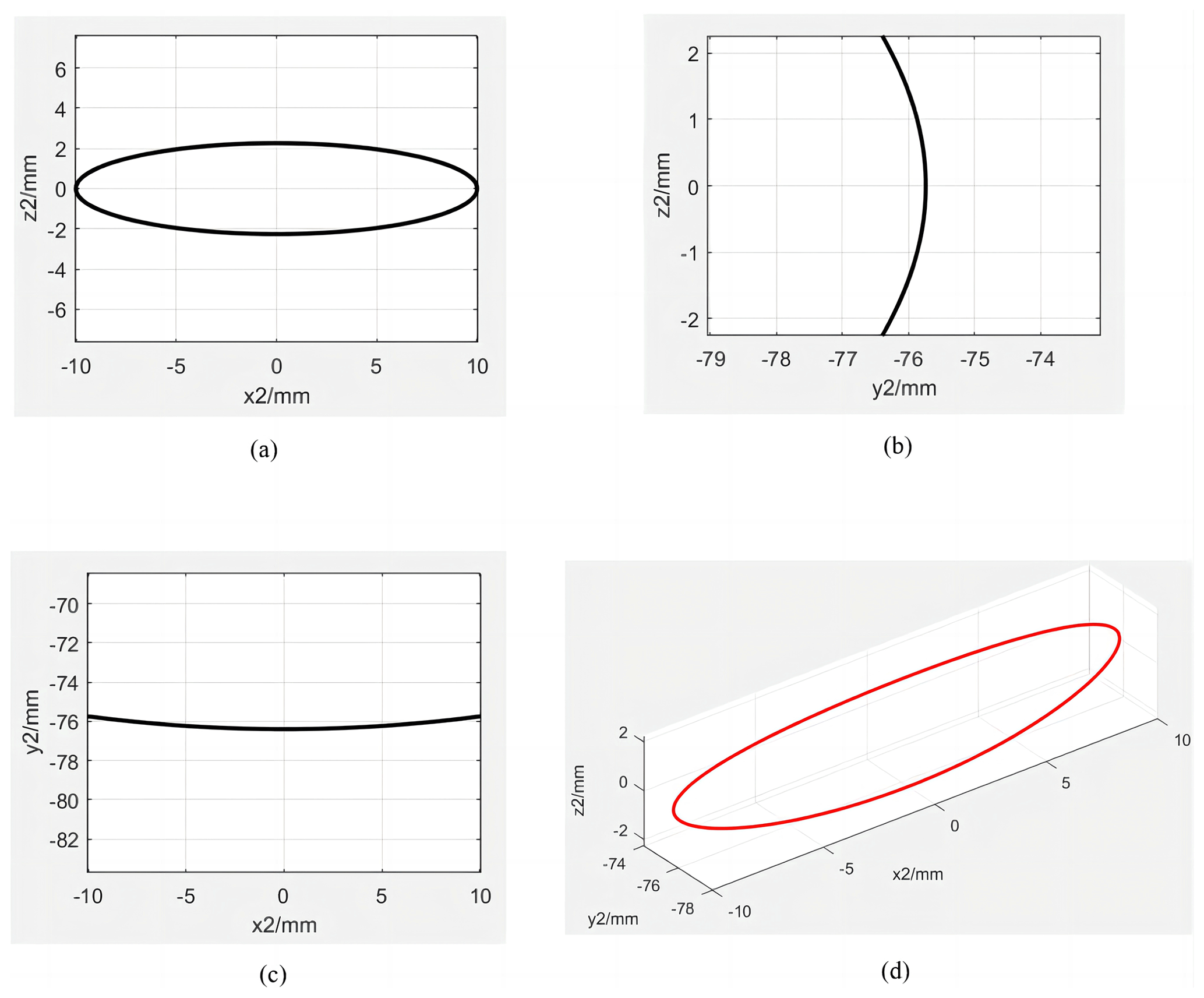
Figure 7Trajectory of the looper tip of the optimized thread-hooking mechanism. (a) Trajectory projection in the O2x2z2 Plane; (b) Trajectory projection in the O2y2z2 Plane; (c) Trajectory projection in the O2x2y2 Plane; (d) 3D view of the trajectory.
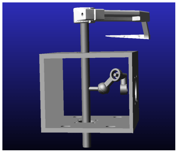
5.1 Kinematics simulation of the mechanism
According to the optimized parameters of the thread-hooking mechanism, the preferable parameters of the thread-hooking mechanism which were obtained from the human–computer interaction optimization method are selected into the virtual prototyping, through the simulation to verify the correctness. Thus, the parameters are used in 3D printing technology to verify the feasibility of the mechanism.
SolidWorks software is applied to build a 3D solid model of the mechanism which is imported into the Adams simulation environment with Parasolid format. The following steps were used. The constraints between the members were added, the relevant parameters were set, the rotating vice of the input bar was taken relative to the ground as the power input, the rotational speed was set as 10 rps (revolutions per second), and the kinematics simulation of the mechanism was carried out (as shown in Fig. 8).
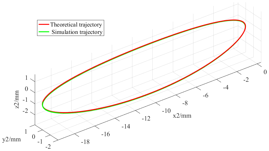
The simulated trajectory of the looper tip is compared with the optimized trajectory in the same spatial coordinate system (as shown in Fig. 9); the two trajectories are basically the same, verifying the correctness of the theoretical model and optimal design results of the mechanism.
5.2 Tests of the mechanism prototype
The high-speed camera tests of the thread-hooking mechanism prototype are conducted in the Key Laboratory of Planting Equipment Technology, Zhejiang Sci-tech University. 3D printing technology is used to process the mechanism parts for building the test prototype. The following steps were taken. Mark points were painted on the looper tip, a Vision Research (Phantom V9.1) high-speed camera was used to record the motion trajectory of the looper tip, and Photoshop software was used to process the video. Dexuan 28HB40-402A stepper motor was selected as the driving motor. The controller is used to send a set of pulses, then the actuator receives the pulses and drives the motor to achieve power input. The mechanism prototype test bench is shown in Fig. 10.
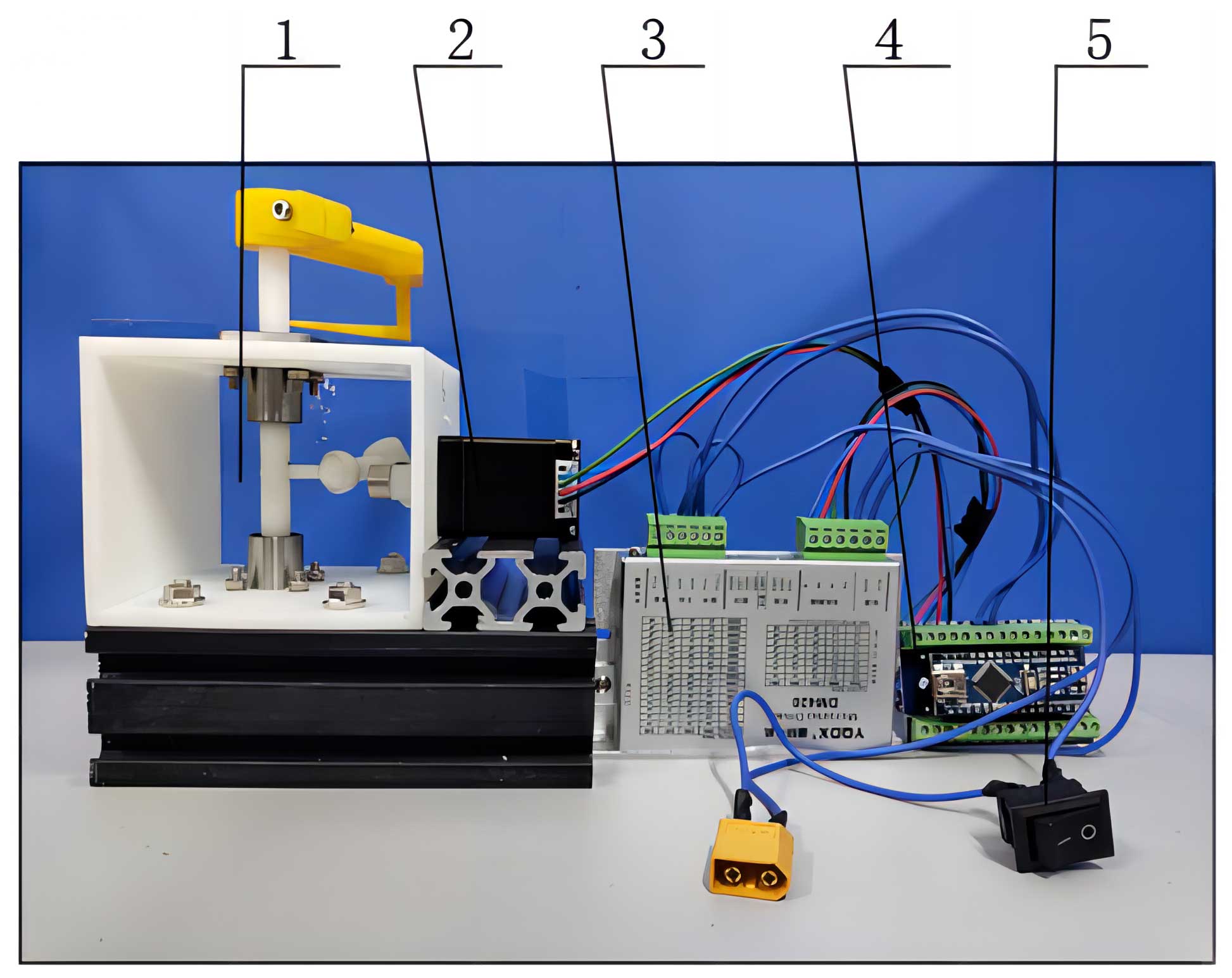
Figure 10The prototype test bench of the thread-hooking mechanism. 1: thread-hooking mechanism, 2: motor, 3: actuator, 4: controller, and 5: switch.
During the tests, the motor runs for 30 s at the stable speed of 600 r min−1. According to Fig. 7, the camera lens was set vertically to three planes of O2x2z2, O2y2z2, and O2x2y2, respectively, for recording, and the camera frequency was set to 480 fps (frames per second). The video files are imported into Photoshop software and transformed into pictures frame by frame. The mark points are marked in the software, the layers are overlapped to display them, and the motion trajectory of the looper tip was obtained as shown in Fig. 11a to c. We measured with vernier calipers and calculated that S is 4.93 mm, θ is 16° measured through the trajectory picture, and L is 21.27 mm through calculation (as shown in Fig. 11d to f).
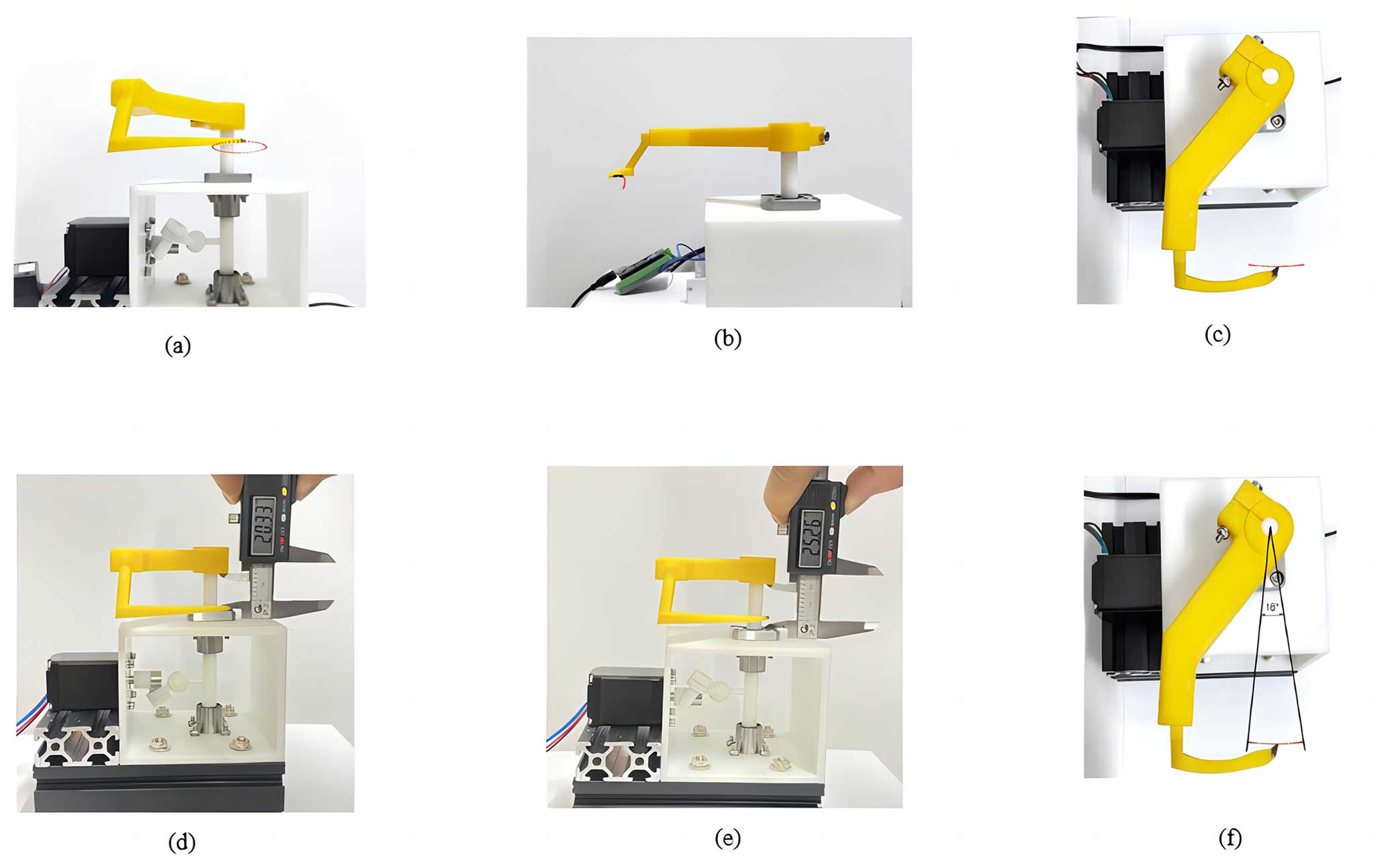
Figure 11Test trajectory and trajectory mapping. (a) Test trajectory recorded in the vertical direction of O2x2z2 plane; (b) the test trajectory recorded in the vertical direction of O2y2z2 plane; (c) the test trajectory recorded in the vertical direction of O2x2y2 plane; (d) the lowest point in the direction of the looper axis; (e) the highest point in the direction of the looper axis; (f) the swing angle of the looper
5.3 Analysis of test results
By comparing the results of the bench test and theoretical analysis of the thread-hooking mechanism, it can be seen that the test trajectory and the theoretical trajectory of the mechanism looper tip are basically the same. Compared with the theoretical values, the test values of S, θ, and L are 0.4 mm, 0.94°, and 1.24 mm bigger, respectively. The main reason for the error between the test and theoretical results is the assembly error of the mechanism prototype, due to the resin material used in the 3D printing technology in the processing of mechanism components, which has a lower density, and the shaking is slightly more noticeable compared to the metal material during operation. At the same time, due to limited processing accuracy and the lubrication effect on connection parts such as ball pairs, some errors may happen. But these errors are low, indicating that the mechanism has a good application feasibility.
In this study, based on the analysis of chain stitch formation principle, a new type of thread-hooking mechanism is proposed; it has a novel RRSC spatial four-bar linkage mechanism, which could achieve a continuous supply of bobbin thread. It shows that the parameter values of the mechanism meet design expectations, and the mechanism operates in a desired trajectory.
The method of direction cosine matrix and mechanism identity conditions are applied to carry out kinematics analysis of the mechanism, and its kinematics model is established. The human–computer interaction optimization software was developed, and a set of mechanism parameters satisfying the objective requirements was obtained by applying the human–computer interaction optimization method; these values are α23= 90°, α30= 58.5°, L0= 12 mm, L1= 19 mm, L2= 16.7 mm, L3= 0 mm, S0= 11.7 mm, S3= 35.4 mm, and R1= 76.4 mm.
The kinematic simulation analysis of the mechanism is carried out, verifying the correctness of the theoretical model and design results of the mechanism. Based on the 3D printing technology, the mechanism prototype is established, and the prototype test bench is developed. The high-speed photographic kinematic tests are carried out, and the test results of kinematic characteristics of the mechanism prototype show that the mechanism has a good application feasibility.
All the data and codes used in this paper can be obtained on request from the corresponding author.
BY is the lead author of this article and was responsible for collecting the research literature, organizing the paper structure, and writing the paper. XW wrote the paper and edited the pictures. MZ is the corresponding author of this paper, conceived the research, and was responsible for revising the paper. PY and WH co-authored the manuscript and provided suggestions for the revision and correction of the paper.
The contact author has declared that none of the authors has any competing interests.
Publisher’s note: Copernicus Publications remains neutral with regard to jurisdictional claims made in the text, published maps, institutional affiliations, or any other geographical representation in this paper. While Copernicus Publications makes every effort to include appropriate place names, the final responsibility lies with the authors.
The authors thank the reviewers for their critical and constructive review of the article.
This research has been supported by the National Natural Science Foundation of China (grant no. 32171899).
This paper was edited by Wuxiang Zhang and reviewed by Çağlar Uyulan and two anonymous referees.
Bai, S. P., Li, Z. Y., and Angeles, J.: Exact Path Synthesis of RCCC linkages for a Maximum of Nine Prescribed Positions, J. Mech. Robot., 14, 021011, https://doi.org/10.1115/1.4052336, 2021.
Chen, F. F., Ju, H. H., Yu, M., Kang, J., and Sun, S.: An Analytical Quaternion and its Applications to Inverse Kinematics of 6R Manipulators, Journal of Mechanical Engineering, 58, 31–40, https://doi.org/10.3901/JME.2022.09.031, 2022.
Haruhiko, K. and Sei, K.: Automated Bobbin Exchanger Device, US Patent, US9598806B2, https://ppubs.uspto.gov/dirsearch-public/print/downloadPdf/9598806 (last access: 2 April 2024), 2017.
Hu, X. D., Huang, D. M., and Peng, L. H.: Design of automatic bobbin thread replacing system in super Multihead embroidery machine, Journal of Textile Research, 36, 134–139, https://doi.org/10.13475/j.fzxb.20140403606, 2015.
Jana, P.: Automation in sewing technology, in: Automation in Garment Manufacturing, Elsevier, India, 199–236, https://doi.org/10.1016/B978-0-08-101211-6.00009-4, 2018.
Jared, M. and Brain, M.: Bobbinless sewing machine and stitch, US Patent, US10060061B2, https://ppubs.uspto.gov/dirsearch-public/print/downloadPdf/10060061 (last access: 2 April 2024), 2018.
Li, X. G., Wei, S. M., Liao, Q. Z., and Zhang, Y.: A novel analytical method for four-bar path generation synthesis based on Fourier series, Mech. Mach. Theory, 144, 103671, https://doi.org/10.1016/j.mechmachtheory.2019.103671, 2019.
Liu, W., Sun, J. W., and Chu, J. K.: Synthesis of a spatial RRSS mechanism for path generation using the numerical atlas method, J. Mech. Design, 142, 012303, https://doi.org/10.1115/1.4044110, 2019.
Mohan, S. and Corves, B.: Inverse dynamics and trajectory tracking control of a new six degrees of freedom spatial 3-RPRS parallel manipulator, Mech. Sci., 8, 235–248, https://doi.org/10.5194/ms-8-235-2017, 2017.
Rodríguez-González, S. J., Suárez-Velásquez, H. A., Cervantes-Sánchez, J. J., and Rico-Martínez, J. M.: A novel approach for the rigid body guidance synthesis of planar RRPR linkages, J. Mech. Sci. Technol., 34, 843–854, https://doi.org/10.1007/s12206-020-0134-3, 2020.
Templeton, C. D. H.: High velocity bobbin sewing system, US Patent, US10156034B1, https://ppubs.uspto.gov/dirsearch-public/print/downloadPdf/10156034 (last access: 2 April 2024), 2018.
Vo, D. T., Kheylo, S., and Nguyen, V. Q.: Kinematic and dynamic accuracy of spherical mechanisms, Mech. Sci., 13, 23–30, https://doi.org/10.5194/ms-13-23-2022, 2022.
Wang, Z., Fu, H., and Fan, Z. Q.: Research and Design of Automatic Laying and Quilting Equipment for Multi-layer Insulation of Spacecraft, in: Proceedings of 2019 2nd International Conference on Sustainable Energy, Environment and Information Engineering (SEEIE 2019), Beijing, China, 24–25 March 2019, 184, 59–63, 2019.
Wu, L. G.: Formation principle of double-needle suture trace, Machine Design & Research, 7, 4–6, https://doi.org/10.13952/j.cnki.jofmdr.1991.03.002, 1991.
Ye, B. L., Yu, G. H., Chen, Z. W., and Zhao, Y.: Kinematics modeling and parameters optimization of seedling pick-up mechanism of planetary gear train with eccentric gear and non-circular gear, Transactions of the Chinese Society for Agricultural Machinery, 27, 7–12, https://doi.org/10.3969/j.issn.1002-6819.2011.12.002, 2011.
Ye, B. L., Liu, A., Yu, G. H., and Luo, C. X.: Parameters Optimization with Human-computer Interaction Method and Experiment of Vegetable Seedling Pick-up Mechanism, Transactions of the Chinese Society for Agricultural Machinery, 44, 57–62, https://doi.org/10.6041/j.issn.1000-1298.2013.02.012, 2013.
Yi, P. X., Du, H., Lu, H. N., and Lai, W. X.: Research and Application of Automatic Bottom Bobbin Changer for Industrial Sewing Machine, Machine Tools and Hydraulics, 42, 33–35, 41, https://doi.org/10.3969/j.issn.1001-3881.2014.21.009, 2014.
Zhang, Q. X.: Analysis and synthesis of the space mechanism, China Machine Press, Beijing, Book No. 15033.5506, 1984.
Zhang, J. Y.: Displacement analysis of spatial mechanism using dual-transformation matrices and geometry of mechanism, Journal of Nanjing University of Science and Technology, 9, 16–23, https://doi.org/10.14177/j.cnki.32-1397n.1985.01.003, 1985.
Zhou, J. R. and Jiang, L.: Structural optimization design of high-speed computerized embroidery machine, Journal of Textile Research, 39, 133–138, https://doi.org/10.13475/j.fzxb.20170405107, 2018.
- Abstract
- Introduction
- Scheme design of the thread-hooking mechanism
- Kinematics model of the thread-hooking mechanism
- Optimal design of the thread-hooking mechanism
- Experiments of the thread-hooking mechanism
- Conclusions
- Code and data availability
- Author contributions
- Competing interests
- Disclaimer
- Acknowledgements
- Financial support
- Review statement
- References