the Creative Commons Attribution 4.0 License.
the Creative Commons Attribution 4.0 License.
 | 09 Oct 2023
Motion planning and control strategy of a cable-driven body weight support gait training robot
Tao Qin
Qianpeng Wang
Wei Su
Chao Wei
Yanduo Zhang
Jianwei Zhang
In this paper, a cable-driven body weight support gait training robot (C-BWSGTR) that provides patients with partial body weight support as well as a kind of stable gait training driving force was designed; this device enabled those patients to walk again. Firstly, the overall configuration of the C-BWSGTR was determined, and the structural composition and working principle of the robot were established. Secondly, the vector algebra method was applied to carry out the kinematic analysis and establish the mathematical model of the C-BWSGTR. The displacement of each cable during the patient gait training was also calculated. Thirdly, the motion planning of the C-BWSGTR was carried out in stages, using the time–phase distribution relationship based on an S-shaped speed curve. Meanwhile, the displacement, speed, and acceleration of each cable during the patient gait training were calculated and corresponding change curves were generated. Finally, a position servo composite control strategy for the C-BWSGTR was designed by analyzing the robot's dynamic characteristics of the forward channel transfer function. The simulation analysis and prototype experiment in this paper verified that the designed composite position servo control strategy can meet the requirements of the system with respect to stability and a fast response of the system to the loading command.
- Article
(5434 KB) - Full-text XML
- BibTeX
- EndNote


With the intensification of population aging, the number of patients with lower-limb movement disorders caused by factors such as body aging and diseases is increasing, especially due to high-risk diseases such as stroke, which are likely to cause hemiplegia and lead to motor dysfunction in the human body (Zhang et al., 2022; Li et al., 2021). With the continuous development and improvement of rehabilitation medicine, relevant clinical studies have shown that the human central nervous system has a high resilience and plasticity (Dong et al., 2021; Sabapathy et al., 2022). For patients with lower-limb movement disorders caused by diseases such as accidents and strokes, in addition to necessary surgical treatment and drug treatment, scientific rehabilitation training and treatment can effectively help patients restore their basic exercise ability (Hramov et al., 2021). Therefore, as the crystallization of modern rehabilitation engineering technology, the body weight support gait training robot (BWSGTR) has been highly anticipated by scientists and medical workers and has gradually become a research hot spot in the field of medicine and engineering (Hobbs and Artemiadis, 2020; Ye et al., 2020).
According to the configuration classification of robots, the BWSGTR can be roughly divided into exoskeleton and end-effector robot types (Qassim and Wan Hasan, 2020). The most famous exoskeleton robot is Lokomat (Jezernik et al., 2003; van Kammen et al., 2016), developed by the Swiss company Hocoma and the Balgnrist University Hospital. The robot provides patients with a certain body weight support via a closed-loop feedback control, which can effectively avoid the adverse effects of passive weight support on patients. However, its body weight support system adopts a single-cable suspension form; thus, it cannot effectively control the up and down movement of the body's center of gravity. Typical end-effector robots mainly include pedal-driven and cable-driven robots.
The LOKOHELP, G-EO system, Anklebot and STRING-MAN are all end-effector robots. The LOKOHELP trainer (Zhang and Ban, 2019), developed by the German company WOODWAY, is a typical pedal-driven robot. The robot drives the patient to perform gait training via an exercise pedal-driven mechanism, and it can stimulate the quadriceps receptors at the same time, which is beneficial to reshape the cranial nerve with respect to walking posture function. However, because of the fixed trajectory of its motion pedal-driven mechanism, the robot makes it impossible to adjust the walking posture according to different patient conditions. The G-EO system uses a body weight support system and exercise pedal-driven mechanism. The body weight support system provides the patient with body weight support through shoulder suspension and real-time control of the patient's center of gravity. The exercise pedal-driven mechanism controls the patient's gait trajectory during gait training in real time and can adjust the gait trajectory to simulate the training environment, such as flat walking or climbing stairs. However, the G-EO system gait corrector is directly fixed to both feet, and the degree of freedom (DOF) of the ankle joint rotation is canceled; therefore, the training trajectory is quite different from an actual human gait trajectory. The Massachusetts Institute of Technology has developed a lower-limb pedal-driven end-effector rehabilitation robot named Anklebot. Patients place their lower limbs on the traction device of the robot, and the robot simulates the movement of the human ankle through a motor drive system so as to achieve traction and promotion of patients' lower limbs for rehabilitation training. However, Anklebot is a rigid rehabilitation training robot with passive training. The STRING-MAN (Surdilovic et al., 2007; Wang et al., 2018), developed by the Fraunhofer Institute in Germany, is a typical cable-driven robot. This robot is composed of a posture control cable-driven mechanism and an automatic body weight support cable-driven mechanism that ensure the safety and effectiveness of the system during the training process. However, it is difficult to operate due to its complex control system. The multi-robot concept (Tuci et al., 2018; Park et al., 2017) was developed by Harvard University. The system consists of a cable-driven mechanism and a walking mechanism. A tracking test of the system's motion performance showed that this system can achieve excellent rehabilitation training effects. However, limited by the size of the patient's lower limbs, it had a much narrower application than expected.
Because the cable-driven parallel mechanism offers distinct advantages, including minimal transmission vibration (Zou et al., 2022), low motion inertia (Chen et al., 2019; Song et al., 2023), a high load mass ratio (Niu et al., 2017), and a large working space (Wang et al., 2021; Zou et al., 2019), it is not easy to cause reinjury to the affected limb during the training process. Therefore, it is very suitable for the rehabilitation of patients with limb movement disorders (Ghrairi et al., 2023). The BWSGTR is a new type of rehabilitation robot that organically combines a cable-driven parallel mechanism and a rehabilitation training robot (Barbosa et al., 2018). Compared with the traditional rehabilitation training mode, it has the advantages of high flexibility, high precision, and high intelligence. It can provide patients with scientific and effective training and help them restore their normal gait and walking ability (Tang, 2014). Therefore, a cable-driven body weight support gait training robot (C-BWSGTR) is designed for the practical needs of patient rehabilitation training. It can simulate the normal law of movement with respect to the center of gravity and gait trajectory, and it can provide patients with a certain body weight support and a suitable and stable walking driving force, thereby helping patients to recover a certain walking ability.
The current rehabilitation training robots often lack flexibility due to the use of rigid exoskeletons and pedal mechanisms. However, the C-BWSGTR abandons the exoskeleton and pedal mechanisms, instead using cables and supporting wearable devices to provide a comfortable user environment, and it controls the end-effector and the cable-driven parallel mechanism through the gait training system to provide patients with a variety of training walking postures and an appropriate gait size and stable gait driving force during rehabilitation. Single-cable-driven body weight support is widely used in rehabilitation robots, but using double-cable-driven body weight support, as used by the C-BWSGTR, can achieve better therapeutic results. Double-cable-driven body weight support can provide a finer and more controllable treatment effect with a wider adjustment range, which is suitable for more strict and complex treatment needs. It can also improve the stability and safety of the robot, thereby effectively reducing the accidental injury of patients during the treatment process and improving the success rate and safety of treatment.
The rest of this paper is organized as follows: Sect. 2 gives a brief overview of the structure and characteristics of the C-BWSGTR; Sect. 3 illustrates the kinematic analysis of the C-BWSGTR; Sect. 4 outlines the motion planning of the C-BWSGTR and the influence of different time–phase distribution relationships on the gait trajectory of the lower limb undergoing rehabilitation; Sect. 5 establishes the control system model of the C-BWSGTR and verifies the effectiveness of the position servo composite control strategy via simulation analysis; Sect. 6 presents the prototype experiment used to compare and analyze the feasibility of the robot to achieve rehabilitation training; and conclusions are drawn and further work is forecasted in Sect. 7.
Relevant studies have shown that the collaborative work of a body weight support system and gait training system can improve patients' gait quality, improve gait coordination and consistency, and increase patients' self-confidence during gait rehabilitation training. The proposed C-BWSGTR consists of a body weight support system and gait training system, as shown in Fig. 1. The body weight support system is mounted on the top of the weight frame, which has two motors that drive bilateral cables to control the movement of the body's center of gravity. During gait rehabilitation training, the patient wears a body weight support vest and some wearable bandages. The body weight support system provides partial body weight support for the patient via double-shoulder-cable suspension. It can reduce the pressure on the joints of the patients' lower limbs and the pain experienced by patients during gait rehabilitation training. The gait training system contains two sets of 1R2T (one rotation and two translation) parallel cable-driven mechanisms. The unilateral 1R2T mechanism, containing four drive units, can realize movement of the lower limb with 3 DOFs in the sagittal plane. It provides the patient with a suitable and stable driving force for walking and helps patients more successfully recover their normal gait, avoid an irregular and uncoordinated gait, and reduces patient discomfort during gait rehabilitation training by unifying the rhythm and rule of gait.
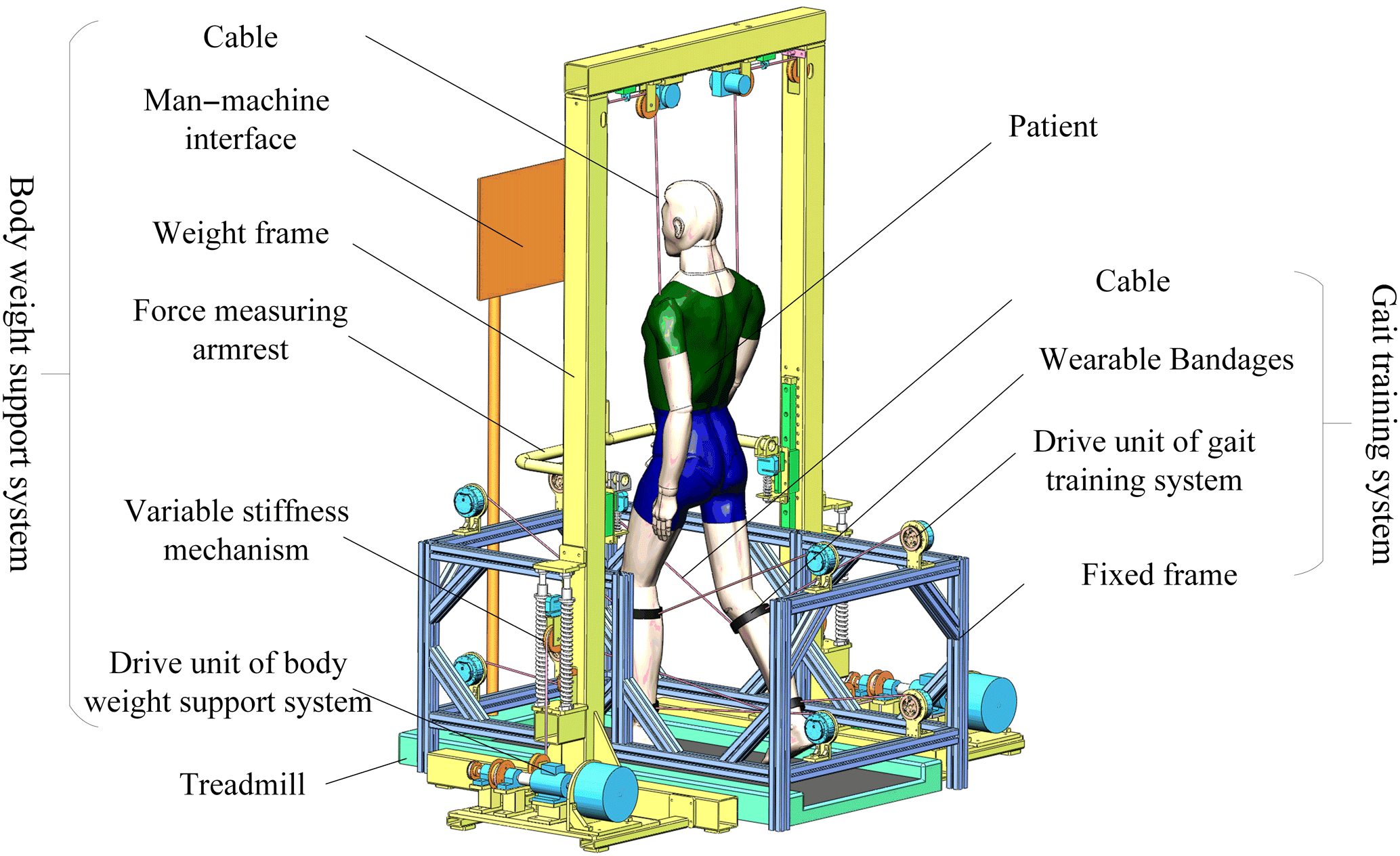
The body weight support system and the gait training system working together can maximize the promotion of patients' rehabilitation, which can not only improve the effect of rehabilitation training but also reduce the risk of rehabilitation training and ensure the safety and effectiveness of patient's gait rehabilitation training.
The characteristics of the C-BWSGTR designed in this paper are as follows:
-
It conforms to the normal laws of motion for the human body with respect to walking. The body weight support system uses two motors on both sides to independently control the position of the center of gravity as well as the up and down movement of the human body while the gait training system simulates the normal gait trajectory of the human body through the parallel structure of two sets of 1R2T cables.
-
It has a larger workspace. Because the robot adopts the form of cable transmission, it has a larger working space than the rigid parallel robot.
-
It has a variety of rehabilitation modes. The robot can choose both active and passive training modes according to different rehabilitation stages and rehabilitation needs.
-
It is of great convenience to operate. Both the body weight support system and the gait training system are of modular design, which makes the layout of the drive unit more convenient to change. Thus, the size of the working space and the related performance of the robot can be changed accordingly to realize convenient transformation of the space configuration and the plane configuration.
The walking motion of the human body is characterized by periodicity and symmetry. In the process of moving forward, the feet are alternately in contact with the ground. Therefore, when analyzing the kinematics of the robot, only one gait cycle on one side is studied (DeLisa, 1998; Nixon et al., 2005). As the patient's gait training is all performed in the sagittal plane, it is necessary to analyze the 3 DOFs of movement in the sagittal plane, including one rotational motion and two translational motions. The inverse kinematics and forward kinematics of the robot are analyzed using the vector algebra method and the iterative method, respectively.
3.1 Inverse kinematics modeling of the C-BWSGTR
A schematic diagram of the mathematical model of the C-BWSGTR is shown in Fig. 2. The fixed rectangular coordinate system of the model is set as o, x, and y; the local coordinate system of the moving platform is Pxpyp; and θ is the angle between the fixed platform and the moving platform in the coordinate system. The coordinates of the cable drive unit in the global coordinate system are , , M3(a,b), , and M5(0,c) in the fixed coordinate system, respectively. The coordinates of the tow point in the moving coordinate system are , , P3(e,f), , and .
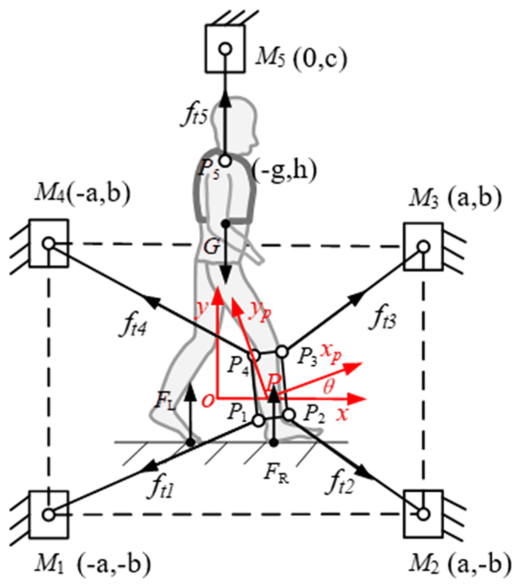
Assuming that the pose of the moving platform is , and the coordinate of point Pi in the moving coordinate system is (Xpi,Ypi), the coordinates of the connection point Pi on the moving platform in the global coordinate system are as follows:
Let Li=PiMi be the vector of the cable in the direction from point Pi to connection point Mi. Let li=∥Li∥ be the length of the cable i, let be the unit vector in the direction of the cable i, and ri=PPi. According to the geometric vector closure principle, the lengths of the five cables are expressed as follows:
In Eq. (2), .
3.2 Forward-kinematics modeling of the C-BWSGTR
As Eq. (2) is a nonlinear equation system, there is sometimes no equation for finding the root, and the approximate solution of the cable length is solved by a numerical calculation method. As a result, the Newton–Raphson iteration method is applied to solve Eq. (2).Using this method, a target point as close as possible to the initial value of iteration is selected. The selected target point is then substituted into the equation for layer-by-layer iteration, and an approximate solution within the error tolerance is finally obtained.
Expanding Eq. (2), the equations containing the three unknowns x, y and θ of the pose of point P can be obtained:
Using the Newton–Raphson iteration method, the matrix equation can be obtained:
Here, JNR is the Newton–Raphson Jacobian matrix:
The general equation for the iterative solution is as follows:
where is the pseudo-inverse of the Jacobian matrix of JNR.
3.3 Kinematics simulation of the C-BWSGTR
In order to understand the motion performance of the C-BWSGTR intuitively, a kinematic simulation of the M function written in MATLAB was carried out, and the displacement of each cable during gait training was calculated. To do so, a set of motion trajectories of a normal human walking gait were selected, and the actual design parameters of the robot were set as follows: a=300 mm, b=150 mm, c=900 mm, e=40 mm, f=50 mm, g=80 mm, and h=40 mm. Those parameters were substituted into the derived kinematic equation (Eq. 2). The kinematics of the robot were simulated and analyzed by writing the M function. The corresponding cable length change curves of the five cables of the moving platform are shown in Fig. 3.
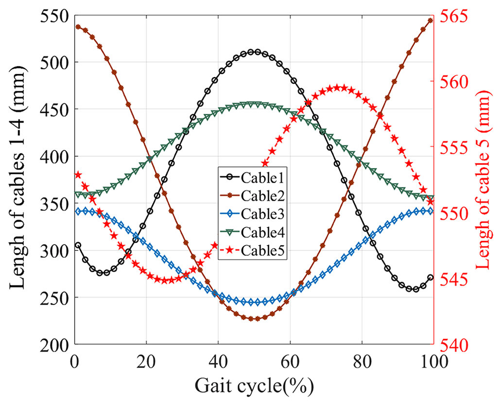
As shown in Fig. 3, the length of cables 1 and 2 varies between 200 and 550 mm, the length of cables 3 and 4 varies between 225 and 475 mm, and the length of cable 5 varies between 540 and 565 mm. According to various standard indicators of the human body and the initial position, the normal stride length on a treadmill is determined to be between 700 and 1000 mm (Lim et al., 2017), and the range of the cable displacement is determined accordingly. Specifically, within a normal gait cycle, when the right foot moves forward and reaches its maximum distance, the displacement of cables 1 and 4 will reach a maximum, whereas the displacement of cables 2 and 3 will reach a minimum. This range reflects the requirement for cable stretching and contraction. The displacement of cable 5 represents the vertical change in the center of mass in the sagittal plane. For example, within a normal gait cycle, the range of the center of mass change is 25 mm based on the initial conditions with respect to the person's height and standing position. Within one cycle, the center of mass fluctuates up and down, with a distance of 25 mm between the lowest and highest points. The length change curves of cables 1 and 2 and of cables 3 and 4 are all continuous and smooth, and the amplitude range is basically the same. However, there is a certain time lag caused by the symmetry between the cable and the regular movement of the moving platform.
As the robot needs to drive the patient to perform rehabilitation training by simulating normal human walking, it is necessary to carry out motion planning for the C-BWSGTR for different rehabilitation training tasks. The main aim is to determine the displacement, velocity, and acceleration of each cable through kinematics theory according to the rehabilitation training task and the constraints of the external environment. The relationship between these variables and time is expressed by a functional relationship.
4.1 Gait cycle analysis
As shown in Fig. 4, a gait cycle is the time from heel landing to heel landing again on the same side. A gait cycle includes two stages: the support phase and the swing phase. The support phase represents the contact and bearing period between the sole and the ground, which accounts for 60 % of the whole gait cycle. The swing phase represents the period in which the sole of the foot leaves the ground and swings forward, accounting for 40 % of the total gait cycle.
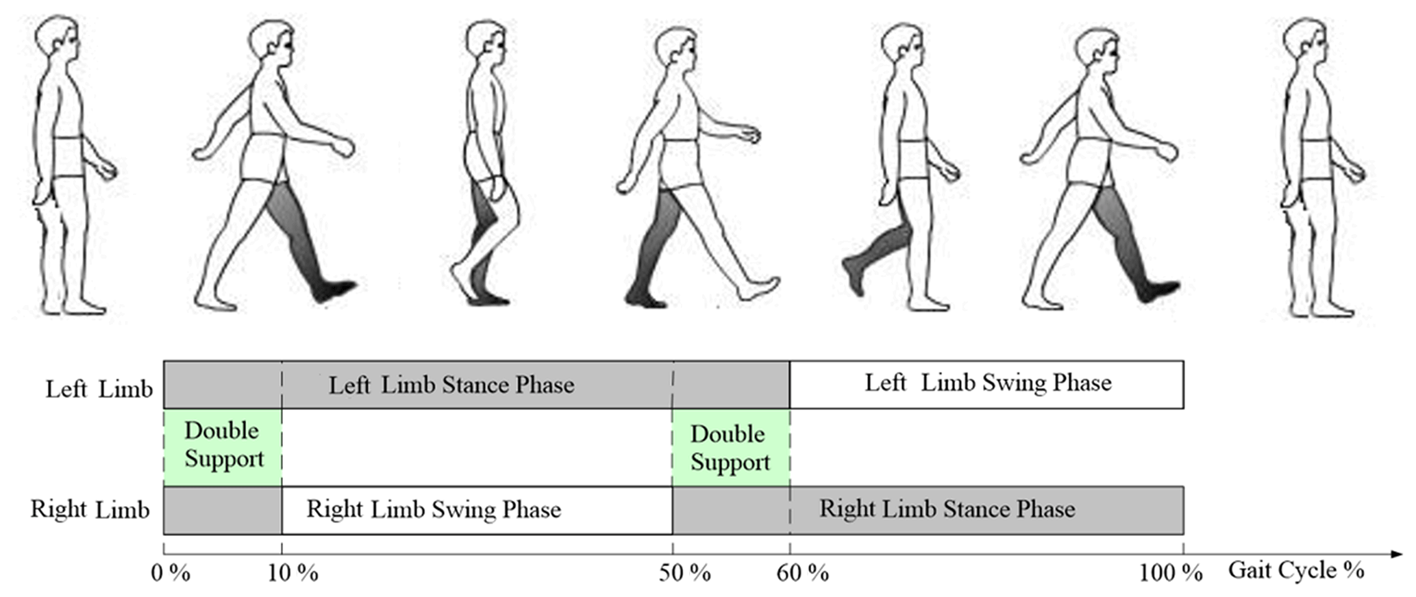
Therefore, in this paper, the initial study selected λ=60 %, which was consistent with the normal gait law. Generally speaking, the proportional distribution of the support phase and the swing phase does not change according to the different body characteristics of the person. In the gait cycle of patients with lower-limb movement disorders, due to weakening muscle strength and deterioration of the control ability, the swing phase time will become longer in order to ensure the stability of the body's center of gravity; therefore, we selected λ=50 %. This adjustment increases the swing phase time and reduces the swing amplitude and speed of patients with lower-limb movement disorders.
4.2 Motion planning method for the C-BWSGTR
Due to the influence of motion inertia, when the swing phase (SWP) and the stand phase (STP) alternate, the support force of the ground on the human body is greater than the human body's gravity at that moment, increasing the possibility of causing injury to the affected limb and, thus, affecting the stability and safety of the gait training. Therefore, when planning the motion of the C-BWSGTR, it is necessary to ensure that the acceleration during the alternating SWPs and STPs are equal, thereby ensuring the stability and safety of the training process.
As shown in Fig. 5, the S-shaped speed curve can control the rate of change in acceleration; the acceleration curve is continuous and the speed connection is smooth, thereby avoiding the impact force and inertia force generated during the alternation of the SWPs and STPs during walking and improving the stability and safety of the training process (Luo et al., 2021; Li et al., 2017). Therefore, the motion planning of the robot is designed based on the S-shaped speed curve and the time–phase distribution relationship. First, a complete gait cycle is divided into SWPs and STPs. These phases are then planned separately according to the movement characteristics and task requirements of each phase. Finally, multiple independent stage plans are combined to form a complete motion plan. With respect to the analysis of the S-shaped velocity curve, its velocity expression is shown in Eq. (6), and the displacement and acceleration expressions can be obtained by integrating and differentiating the velocity expression, respectively, on the basis of Eq. (6).
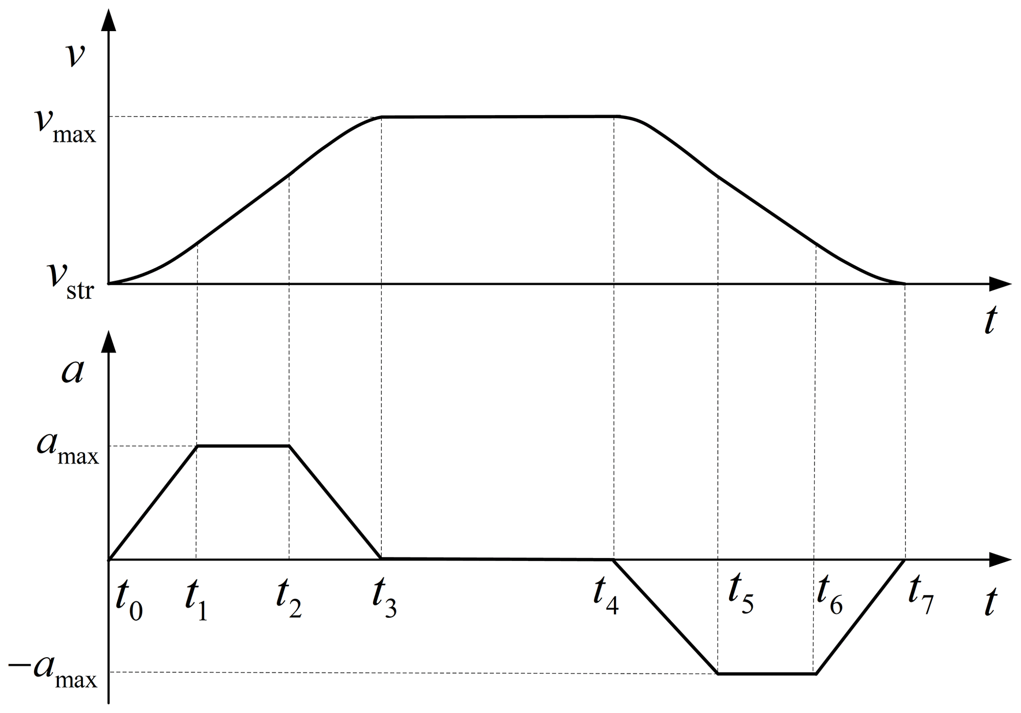
As seen from Fig. 5, vmax is the maximum velocity of the S-type velocity curve; vstr is the initial velocity of the S-type velocity curve; amax is its corresponding maximum acceleration; and J is defined as the jerk, which is the differential between acceleration and time, and its expression is .
4.3 Motion planning simulation for the C-BWSGTR
Due to differences in patients' sex and height, the proportions of the SWPs and STPs are different as well. Assuming that the proportion of the patient's STP in the gait cycle is λ, the proportion of the SWP is 1−λ. We take the respective values of λ=50 % and λ=60 % as examples for motion planning. The robot motion planning program is written using MATLAB, in which the initial and constraint conditions of each cable are set. The simulation calculates the change curves for the displacement, velocity, and acceleration of each cable during one gait cycle, as shown in Figs. 6, 7, and 8, respectively, for a patient with respective gait cycle proportions of λ=50 % and λ=60 %.
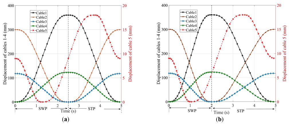
Figure 6The displacement curves of the cables: (a) the displacement curve of the cables when the STP is λ=50 %; (b) the displacement curve of the cables when the STP is λ=60 %.
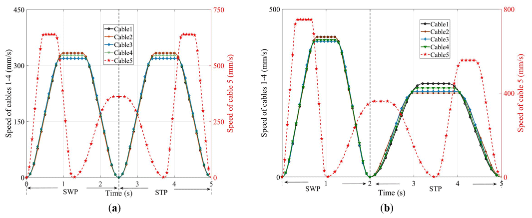
Figure 7The speed change curves of the cables: (a) the speed change curves of the cables when the STP is λ=50 %; (b) the speed change curves of the cables when the STP is λ=60 %.
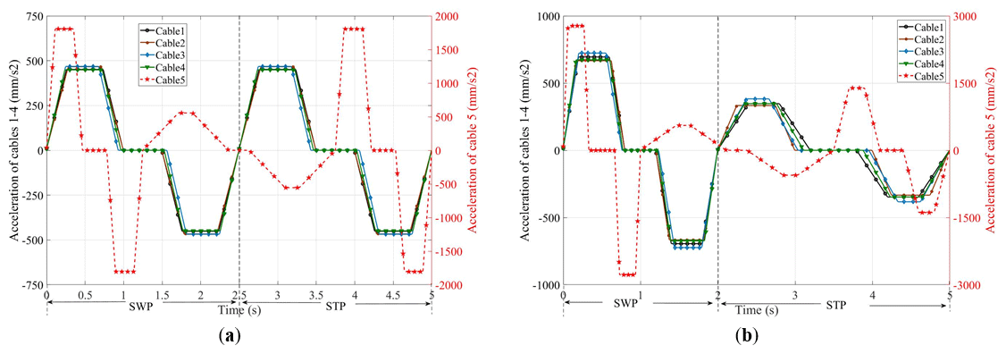
Figure 8The acceleration curves of the cables: (a) the acceleration curves of the cables when the STP is λ=50 %; (b) the acceleration curves of the cables when the STP is λ=60 %.
It can be seen from Figs. 7 and 8 that the speed and acceleration of cables 1–4 are 0 mm s−1 when the SWP and the STP alternate, which avoids the impact generated when the SWP and STP alternate; this ensures the stability and safety of training process. At the same time, as the motion planning of the C-BWSGTR follows the principle of stages, different time–phase distribution relationships can be realized by changing the value of λ, which is suitable for the actual time–phase distribution relationship needs of patients in different rehabilitation stages.
In order to verify whether the motion trajectory of the lower limb after the motion planning meets the actual rehabilitation training requirements, the displacement of each cable obtained by the motion planning in Fig. 6 is substituted into the inverse kinematics Eq. (2), and the planned motion trajectory of the lower limb of the human body is obtained by MATLAB programming. The results are shown in Fig. 9.
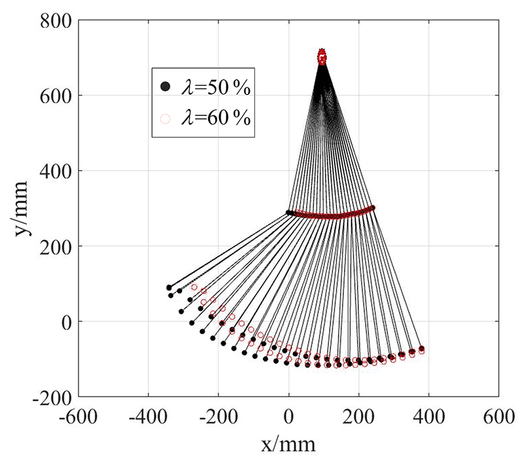
As shown in Fig. 9, compared with the lower-limb motion trajectory obtained by the motion planning using a STP of λ=50 % and a STP of λ=60 %, the hip joint displacement decreases by 10.9 % in the X direction and by 10.1 % in the Y direction, the knee joint displacement decreases by 9.6 % in X direction and by 10.3 % in Y direction, and the ankle joint displacement decreases by 10.1 % in X direction and by 10 % in Y direction. The planned gait trajectory conforms to the normal human gait trajectory and also verifies the correctness of the kinematics and dynamics modeling of the robot.
The C-BWSGTR is a symmetrical structure; in this structure, the body weight support system consists of two sets of drive units with the same characteristics to provide partial body weight support for the patient, and the gait training system consists of eight sets of drive units with the same characteristics to provide patients with an appropriate driving force for walking.
5.1 Drive unit modeling of the C-BWSGTR
With respect to the composition and structure of the robot driving unit shown in Fig. 2, the driving unit mechanistic model of the C-BWSGTR is shown in Fig. 10 and the parameter table of the drive unit of the C-BWSGTR is shown in Table 1 (i=1 is the value of the body weight support system and i=2 is the value of the gait training system). It is of great necessity to reasonably simplify the model. Therefore, the variable stiffness mechanism is simplified as a “mass-spring” model and the cable is simplified as a “mass-spring-damper” model. This simplification of the models results in the following:
- 1.
By simplifying the variable stiffness mechanism into a mass-spring model, the spring stiffness reflects the internal stiffness change in the mechanism, whereas the mass block represents the controlled object. In this way, we can use the adjustment method based on spring stiffness to realize control of the whole variable stiffness mechanism. This simplified technique minimally influences the overall model and selects the parts that are not suitable for modeling in the whole experiment process; this can reduce the complexity of the system and the difficulty of the model and, thus, help to optimize and adjust key parameters.
- 2.
By simplifying the cable into a mass-spring-damping model, the spring is used to simulate the elastic properties of the cable, whereas the damping represents the impact of friction and shear forces in the cable on the motion. The whole model can accurately simulate the dynamic characteristics of the cable in the process of force transfer and realize precise control of the system motion state. The simplified part will produce certain tracking errors, but such changes have no influence on its change trends. This simplified method has important guiding significance for the application of cables in mechanical control and is helpful for structural optimization, control parameter adjustment, and performance improvement. Without simplification, modeling the entire experiment becomes unwieldy, computationally intensive, and inefficient.
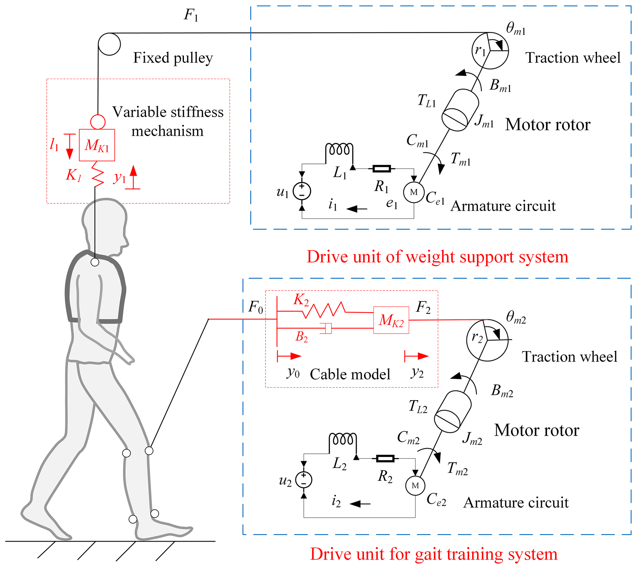
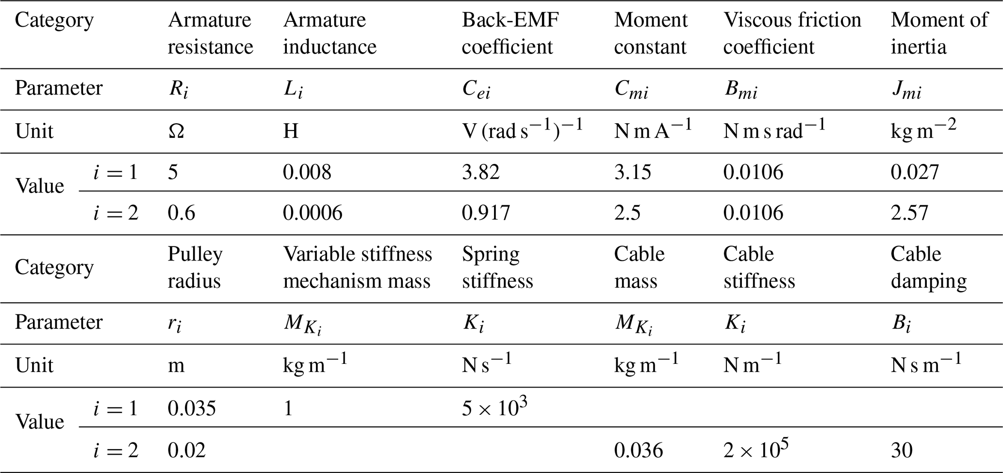
Table 1Nominal parameters of the robot drive unit. Note that EMF refers to electromotive force in the table.
5.2 Dynamic characteristics analysis of the forward channel
According to the mechanistic model of the robot drive unit shown in Fig. 10, the block diagrams of the open-loop models of the body weight support system and the gait training system are obtained as shown in Figs. 11 and 12.

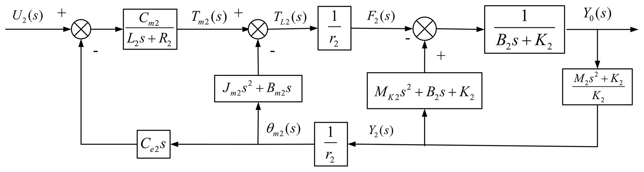
According to Figs. 11 and 12, the forward channel transfer functions of the body weight support system and the gait training system are as follows:
where
where
Substitute the actual parameters of the system in Table 1 into Eqs. (7) and (8) and arrange them as follows:
It can be seen from Eq. (9) that the numerator of the forward channel transfer function of the body weight support system is a second-order differential element, and the denominator consists of an integral element, two first-order inertia elements, and a second-order oscillation element. The gain is KG1=0.67; the turning frequencies of the two first-order inertial elements are ωG1d1=615 rad s−1 and ωG1d2=615 rad s−1, respectively; and the denominator contains an integral term, which is a typical I-type system.
It can be seen from Eq. (10) that the numerator of the forward channel transfer function of the gait training system is a second-order differential link, and the denominator is composed of two second-order oscillation links. The gain is KG2=51 902; the natural frequency of the second-order differential link is ωG2n1=38.56 rad s−1; the damping ratio is ζG2n1=0.0001; the natural frequencies of the second-order oscillation link are ωG2d1=1.09 rad s−1 and ωG2d2=3046.47 rad s−1, respectively; and the damping ratios are ζG2d1=0.5470 and ζG2d2=0.1366, respectively. There is no integral term in the denominator, which is a typical 0-type system.
As shown in Fig. 13a, in the low-frequency band, the amplitude of the body weight support system is slightly attenuated. The phase–frequency response presents a lag characteristic, and the system phase lags about 6.87∘ at 1 Hz. In the middle-frequency band, there is a resonance peak in the amplitude–frequency curve, and the lag degree of the phase–frequency response is intensified. In the high-frequency band, the magnitude of the attenuation becomes weaker. As shown in Fig. 13b, in the low-frequency band, the amplitude of the gait training system has an overall lead, whereas the phase–frequency characteristics slightly lag. The cutoff frequency of the system is ωc=2.95 rad s−1, and the phase angle margin is . In the middle-frequency band, the resonance peak phenomenon appears in the amplitude–frequency curve, and the lag degree of the phase–frequency response is intensified. As a consequence, the system cannot meet the needs of actual rehabilitation training due to its poor dynamics, which makes it necessary to take corresponding measures to deal with this problem.
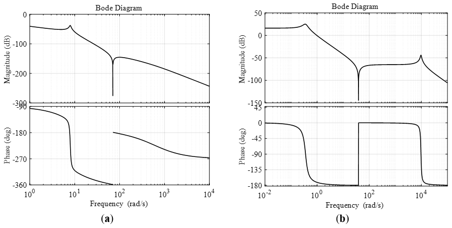
Figure 13Frequency characteristic curve of the forward channel of the position servo system: (a) frequency characteristic curve of the body weight support system; (b) frequency characteristic curve of the gait training system.
5.3 Position servo composite control strategy for the C-BWSGTR
The composite control strategy of the designed robot position servo is shown in Fig. 14, which is mainly composed of a PID (proportional–integral–derivative) correction link and a local differential correction link. The main feedback controller adopts integral control, which is applied mainly to improve the steady-state accuracy of the system. The local differential correction link is mainly used to compensate for the lack of dynamic quality of passive objects.
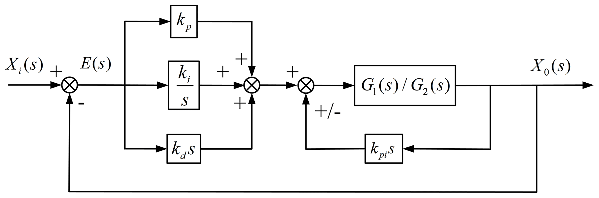
In order to illustrate the effect of the designed robot position servo composite control strategy on improving the rapidity and stability of the system response, according to the principal block diagram of the robot position servo composite control strategy in Fig. 14, the cable displacement curve (Fig. 6) obtained by motion planning is used as the system's input signal, and a simulation analysis of two consecutive gait cycles is performed in MATLAB.
The response curve of the body weight support system is shown in Fig. 15 for kp=68, ki=1.3, kd=45, and kpi=89; the amplitude error in the system before and after correction is about 2.4 %, the phase lag is about 1.8∘, and the adjustment time is about 1.4 s. The response curve of the gait training system is shown in Fig. 16 for kp=235, ki=3.2, kd=16, and kpi=18.4; the amplitude error in the system before and after correction is about 0.2 %, the phase lag is about 1.7∘, and the adjustment time is about 0.3 s. The simulation results show that the designed position servo composite control strategy can improve the dynamic performance of the system loading and meet the system's tracking requirements with respect to the rapidity and stability of the position command.
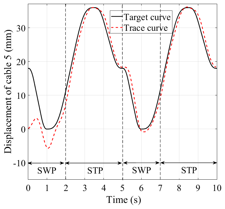
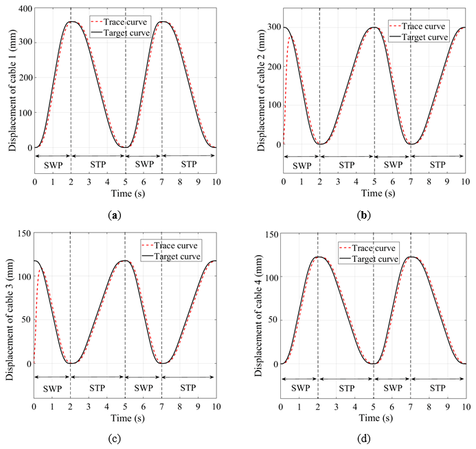
Figure 16Response curve of the position servo control system of the gait training system: (a) system response curve of drive unit 1; (b) system response curve of drive unit 2; (c) system response curve of drive unit 3; (d) system response curve of drive unit 4.
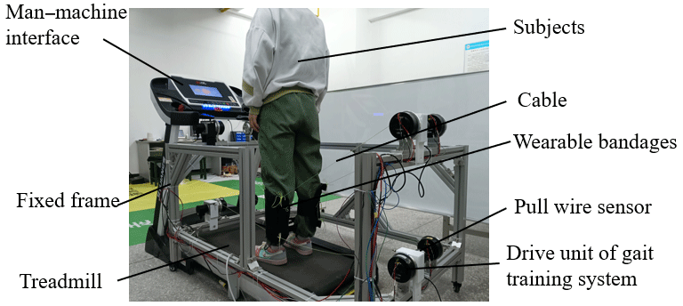
To demonstrate the effectiveness of the proposed motion planning and control strategy, the prototype experimental platform of the gait training system is built as shown in Fig. 17. This experimental platform is composed of a man–machine interface, a fixed frame, one treadmill, eight drive units of the gait training system (motor mode MG8016v1, Shanghai Lingkong Technology Co., Ltd), eight pull-wire sensors (model HPS-M1-20-5V-F, Hongxuan Co., Ltd), and wearable bandages and cables. The left and right drive units are installed at the intersection of the crossbeam of the rack and the sagittal plane of the affected limb to ensure that the four cables on each side are in the same plane as the lower limb requiring rehabilitation. At the same time, each drive unit is equipped with a pull-wire sensor to monitor and feedback the displacement of each cable in real time, so as to achieve gait rehabilitation training using complex lower-limb multidirectional position servo composite control in space. Two sets of 1R2T cable-driven parallel mechanisms are used to pull the wearable leg bandages in order to drive the lower limb for gait rehabilitation training.
The prototype experiment was conducted by employing the position servo composite control strategy with a healthy subject. The weight and height of the subject were 62 kg and 170 cm, respectively. The actual responses of each drive unit, including two cycle steps, are shown in Fig. 18: the solid line represents the actual experimental curves and the dotted line represents the desired target curves. The actual running effect and tracking curves indicate that the designed position servo composite controller has good tracking performance and can meet the requirements of the system with respect to stability and a fast response to the loading command. The motion planning method can be applied to the rehabilitation needs of the actual phase distribution relationship of patients in different rehabilitation stages. Moreover, the position servo composite control strategy can meet the requirements of normal gait rehabilitation training.
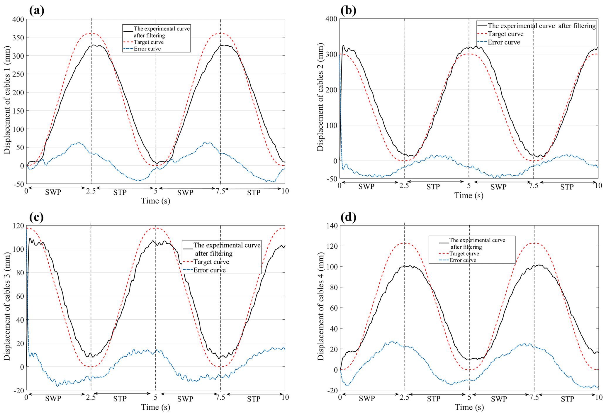
Figure 18The response curves of the position servo control system of the gait training system are obtained from the experimental data: (a) system response curves of drive unit 1; (b) system response curves of drive unit 2; (c) system response curve of drive unit 3; (d) system response curves of drive unit 4. The error curves are the experimental curve after subtracting the filter from the target curve.
A cable-driven body weight support gait training robot is designed to help provide patients with partial body weight support and a stable walking driving force, thereby assisting them with normal gait rehabilitation training. The main highlights of this work are as follows:
- 1.
A kinematic model of the robot was implemented using the vector algebra method, and the displacement of each cable during the patient's gait training was calculated.
- 2.
Based on an S-shaped velocity curve, the motion planning of the robot was carried out using a time–phase distribution relationship, and the variation curves of the displacement, velocity, and acceleration of each cable during training were solved. The simulation results show that the rehabilitation training needs of different time–phase distribution relationships can be met by changing the value of λ.
- 3.
By analyzing the dynamic characteristics of the transfer function of the forward channel of the robot, a composite position servo control strategy was designed. The simulation analysis verified that the designed controller can meet the requirements of the robot system with respect to stability and a fast response to the loading command. Furthermore, the prototype experimental results show that the motion planning and position servo composite control strategy can meet the gait rehabilitation requirements.
Future work will further improve the robot's structure and control algorithms to enhance its performance and applicability and will verify the accuracy and stability of the robot control strategies. For instance, enhancing the robot's adaptability and level of intelligence would allow it to automatically adjust its motion trajectory and force based on the real-time patient status and rehabilitation progress, thereby enhancing rehabilitation outcomes and user experience. Furthermore, integrating the robot with technologies such as virtual reality would create more realistic and immersive rehabilitation environments, thereby increasing patient engagement and improving rehabilitation effectiveness.
The C-BWSGTR is extensively applicable and adaptable, making it suitable for various patient populations and rehabilitation scenarios. For patients with conditions such as stroke, spinal cord injury, and muscle atrophy, the robot can provide appropriate body weight support and walking assistance, thereby facilitating gait training and rehabilitation. Additionally, the robot can be utilized in rehabilitation training for elderly individuals and people with disabilities, thereby improving their quality of life and self-care abilities.
The code is available from the corresponding author upon request.
The data are available from the corresponding author upon request.
All authors contributed to conceiving and designing the study. The conceptual design and method were proposed by TQ and YZ, the control strategy method was proposed by JZ, the robot configuration design and motion planning were completed by CW and TQ, and the control strategy and prototype experiment were contributed by QW and WS. All authors have read and approved the final paper.
The contact author has declared that none of the authors has any competing interests.
Publisher’s note: Copernicus Publications remains neutral with regard to jurisdictional claims made in the text, published maps, institutional affiliations, or any other geographical representation in this paper. While Copernicus Publications makes every effort to include appropriate place names, the final responsibility lies with the authors.
This research was funded by the Scientific Research Project of Education Department of Hubei Province (grant no. D20222603), the Science and Technology Innovation Team of Hubei University of Arts and Science (grant no. 2022pytd01), and the Graduate Innovation Program Project of Hubei University of Arts and Science (grant no. YCX202305).
This paper was edited by Zi Bin and reviewed by three anonymous referees.
Barbosa, A. M., Carvalho, J. C. M., and Gonçalves, R. S.: Cable-driven lower limb rehabilitation robot, J. Braz. Soc. Mech. Sci., 40, 1–11, https://doi.org/10.1007/s40430-018-1172-y, 2018.
Chen, Q., Zi, B., Sun, Z., Li, Y., and Xu, Q.: Design and development of a new cable-driven parallel robot for waist rehabilitation, IEEE-ASME T. Mech., 24, 1497–1507, https://doi.org/10.1109/TMECH.2019.2917294, 2019.
DeLisa, J. A.: Gait analysis in the science of rehabilitation, Scientific and Technical Publications Section, Washington D.C., https://api.semanticscholar.org/CorpusID:60320724 (last access: September 2023), 1998.
Dong, M., Zhou, Y., Li, J., Rong, X., Fan, P., Zhou, X., and Kong, Y.: State of the art in parallel ankle rehabilitation robot: a systematic review, J. NeuroEng. Rehabil., 18, 1–15, https://doi.org/10.1186/s12984-021-00845-z, 2021.
Ghrairi, K., Chaker, A., Salah, S., and Bennour, S.: Development of a cable-driven parallel robots for functional rehabilitation, design and modeling of mechanical systems Springer, Cham, 554–563, https://doi.org/10.1007/978-3-031-14615-2_62, 2023.
Hobbs, B. and Artemiadis, P.: A review of robot-assisted lower-limb stroke therapy: unexplored paths and future directions in gait rehabilitation, Front. Neurorobotics, 14, 19, https://doi.org/10.3389/fnbot.2020.00019, 2020.
Hramov, A. E., Maksimenko, V. A., and Pisarchik, A. N.: Physical principle of brain–computer interfaces and their applications for rehabilitation, robotics and control of human brain states, Physics Reports, 918, 1–133, https://doi.org/10.1016/j.physrep.2021.03.002, 2021.
Jezernik, S., Colombo, G., Keller, T., Frueh, H., and Morari, M.: Robotic Orthosis Lokomat: a rehabilitation and research tool, Neuromodulation, 6, 108–115, https://doi.org/10.1046/j.1525-1403.2003.03017.x, 2003.
Li, L., Fu, Q., Tyson, S., Preston, N., and Weightman, A.: A scoping review of design requirements for a home-based upper limb rehabilitation robot for stroke, Top. Stroke Rehabil., 29, 449–463, https://doi.org/10.1080/10749357.2021.1943797, 2021.
Li, X. and Chen, L.: Research on the Asymmetric S-type Curve Based on the Position, in: Proceedings of the 2017 5th International Conference on Frontiers of Manufacturing Science and Measuring Technology (FMSMT 2017), Atlantis Press, 1591–1598, https://doi.org/10.2991/fmsmt-17.2017.310, 2017.
Lim, Y. P., Lin, Y. C., and Pandy, M. G.: Effects of step length and step frequency on lower-limb muscle function in human gait, J. Biomech., 57, 1–7, https://doi.org/10.1016/j.jbiomech.2017.03.004, 2017.
Luo, H., Zhao, D., and Fu, W.: Speed Planning Algorithm Based on Improved S-Type Acceleration and Deceleration Model, Journal of Shanghai Jiaotong University (Science), 26, 786–793, https://doi.org/10.1007/s12204-021-2322-4, 2021.
Niu, J., Yang, Q., Chen, G., and Song, R.: Nonlinear disturbance observe based sliding mode control of a cable-driven rehabilitation robot, in: 2017 International Conference on Rehabilitation Robotics (ICORR), London, UK, 17–20 July 2017, IEEE, 664–669, https://doi.org/10.1109/ICORR.2017.8009324, 2017.
Nixon, M. S., Tan, T. N., and Chellappa, R.: Human identification Based on Gait, Springer, New York, ISBN-13: 978-0387244242, 2005.
Park, E. J., Kang, J., Su, H., Stegall, P., Miranda, D. L., Hsu, W., Karabas, M., Phipps, N., Agrawal, S. K., Goldfield, E. C., and Walsh, C. J.: Design and preliminary evaluation of a multi-robotic system with pelvic and hip assistance for pediatric gait rehabilitation, in: 2017 International conference on rehabilitation robotics (ICORR), London, UK, 17–20 July 2017, IEEE, 332–339, https://doi.org/10.1109/ICORR.2017.8009269, 2017.
Qassim, H. M. and Wan Hasan, W. Z.: A review on upper limb rehabilitation robots, Appl. Sci.-Basel, 10, 6976, https://doi.org/10.3390/app10196976, 2020.
Sabapathy, S., Maruthu, S., Krishnadhas, S. K., Tamilarasan, A. K., and Raghavan, N.: Competent and Affordable Rehabilitation Robots for Nervous System Disorders Powered with Dynamic CNN and HMM, in: Intelligent Systems for Rehabilitation Engineering, edited by: Raut, R., Pathak, P., Kautish, S., and Pradeep, N., John Wiley & Sons, Ltd, 57–93, https://doi.org/10.1002/9781119785651.ch3, 2022.
Song, D., Xiao, X., Li, G., Zhang, L., Xue, F., and Li, L.: Modeling and control strategy of a haptic interactive robot based on a cable-driven parallel mechanism, Mech. Sci., 14, 19–32, https://doi.org/10.5194/ms-14-19-2023, 2023.
Surdilovic, D., Zhang, J., and Bernhardt, R.: STRING-MAN: Wire-robot technology for safe, flexible and human-friendly gait rehabilitation, in: 2007 IEEE 10th International Conference on Rehabilitation Robotics, Noordwijk, Netherlands, 13–15 June 2007, IEEE, 446–453, https://doi.org/10.1109/ICORR.2007.4428463, 2007.
Tang, X.: An overview of the development for cable-driven parallel manipulator, Adv. Mech. Eng., 6, 823028, https://doi.org/10.1155/2014/823028, 2014.
Tuci, E., Alkilabi, M. H. M., and Akanyeti, O.: Cooperative object transport in multi-robot systems: A review of the state-of-the-art, Frontiers in Robotics and AI, 5, 59, https://doi.org/10.3389/frobt.2018.00059, 2018.
van Kammen, K., Boonstra, A. M., van der Woude, L. H. V., Reinders-Messelink, H. A., and den Otter, R.: The combined effects of guidance force, bodyweight support and gait speed on muscle activity during able-bodied walking in the Lokomat, Clin. Biomech., 36, 65–73, https://doi.org/10.1016/j.clinbiomech.2016.04.013, 2016.
Wang, P., Zhang, Q., Li, L., Ru, F., Li, D., and Jin, Y.: Deep learning-based gesture recognition for control of mobile body-weight support platform, 2018 13th IEEE Conference on Industrial Electronics and Applications (ICIEA), Wuhan, China, 31 May–2 June 2018, IEEE, 1803–1808, https://doi.org/10.1109/ICIEA.2018.8398001, 2018.
Wang, Y., Wang, K., Li, X., Mo, Z., and Wang, K.: Control strategy and experimental research of a cable-driven lower limb rehabilitation robot, P. I. Mech. Eng. C-J. Mec., 235, 2468–2481, https://doi.org/10.1109/ACCESS.2021.3083810, 2021.
Ye, J., Wu, H., Wu, L., Long, J., Zhang, Y., Chen, G., Wang, C., Luo, X., Hou, Q., and Xu, Y.: An adaptive method for gait event detection of gait rehabilitation robots, Front. Neurorobotics, 14, 38, https://doi.org/10.3389/fnbot.2020.00038, 2020.
Zhang, M. and Ban, W.: Efficacy evaluation of acupuncture combined with Lokohelp robot rehabilitation for hemiplegia following acute ischemic stroke, Chinese Journal of Primary Medicine and Pharmacy, 697–700, https://doi.org/10.3760/cma.j.issn.1008-6706.2019.06.015, 2019.
Zhang, M., Chen, J., Ling, Z., Zhang, B., Yan, Y., Xiong, D., and Guo, L.: Quantitative Evaluation System of Upper Limb Motor Function of Stroke Patients Based on Desktop Rehabilitation Robot, Sensors-Basel, 22, 1170, https://doi.org/10.3390/s22031170, 2022.
Zou, Y., Qin, T., Wang, N., Li, J., and Xu, M.: Passive force control of multimodal astronaut training robot, Int. J. Adv. Robot. Syst., 16, 1729881419848261, https://doi.org/10.1177/1729881419848261, 2019.
Zou, Y., Wu, X., Zhang, B., Zhang, Q., Zhang, A., and Qin, T.: Stiffness Analysis of Parallel Cable-Driven Upper Limb Rehabilitation Robot, Micromachines-Basel, 13, 253, https://doi.org/10.3390/mi13020253, 2022.