the Creative Commons Attribution 4.0 License.
the Creative Commons Attribution 4.0 License.
 | 17 Mar 2023
Dimensional synthesis of a spherical linkage crank slider mechanism for motion generation using an optimization algorithm
Wei Zhang
Zhen Liu
Wenrui Liu
Jianwei Sun
He Lu
In the present study, Fourier theory is applied to establish the expression of rigid-body poses of a spherical four-bar crank slider rigid-body guidance mechanism. According to an analysis of the harmonic components of the trajectory curve and rigid-body rotation angle, it has a certain relationship with the geometric parameters of the mechanism. On this basis, the rigid-body poses are normalized by preprocessing. Then, the rotation angle of the curve around the y axis and z axis is determined, respectively. The theoretical formulas used for calculating the real sizes and the installation position parameters of the desired spherical four-bar crank slider rigid-body guidance mechanism are established. Besides this, a genetic optimization algorithm and theoretical formulas are applied to solve the dimensional synthesis of motion generation for the spherical four-bar crank slider mechanism. The effectiveness of the proposed method is illustrated by an example. The maximum Euclidean distance error of the rigid-body position of the results with the highest similarity is 0.0086, and the average Euclidean distance error is 0.0044. The maximum error of the rigid-body orientation is 0.0179, and the average error is 0.0065.
- Article
(10476 KB) - Full-text XML
- BibTeX
- EndNote


With the constant advancement of mechanical manufacturing technology and the widespread application of linkage mechanisms, the dimensional synthesis of linkage mechanisms (especially spatial linkage mechanisms (Wei et al., 2013; Liu et al., 2023) becomes increasingly important. In general, the dimensional synthesis of linkage mechanisms entails motion generation, path generation, and function generation.
The purpose of motion generation or rigid-body guidance is to generate a linkage mechanism required to provide guidance via a prescribed sequence of poses (Sandor et al., 1984). Due to the motion generation required for both the position and the orientation, it is highly complex to conduct the process of motion generation. There are many studies conducted on how to achieve motion generation (Lin, 2013). By applying the Buchberger algorithm, Li and Chen (1996) proposed the synthesis of planar four-bar rigid-body guidance. Avilés et al. (1994) put forward an optimum method of synthesis for planar mechanisms. It is applicable to achieve dimensional synthesis for several types of mechanisms and kinematics such as function generation, path generation, motion generation, or a mix of the above types. Hayes and Zsombor-Murrary (2004) developed a general algorithm by means of kinematic mapping. As for rigid-body guidance, this general algorithm combines type and dimensional synthesis of planar mechanisms. Proposed by Yoon and Heo (2012), the constraint force design method enables topology optimization for a planar rigid-body guidance mechanism. With the advantage of pole, inversion, and overlay techniques (Bagci, 1984), a synthesis method for the function, path and motion generation of spherical mechanisms as indicated by Bagci (1984) can be applied in other mechanisms such as spherical slider crank, spherical crank rocker, and spherical cam follower. Lee and Russell (2007) and Lee et al. (2009) proposed a method that is applicable to describe the rigid-body positions of spherical four-bar mechanisms. Ruth and McCarthy (1999) developed a computer-aided design (CAD) system according to Burmester's planar theory and further proposed a motion generation method for the design of spherical linkages. Through the Burmester curve used in computer modeling and geometric construction for the synthesis of spherical mechanisms, Shirazi (2007) synthesized the 4R spherical linkage capable of guiding an antenna meeting four specified postures in a 3D workspace. Alizade et al. (2013) put forward a motion generation method for the synthesis of spherical linkages by providing rigid-body guidance for the spherical four-bar mechanism. Russell and Sodhi (2001) proposed a new method of synthesis for the multiphase motion generation of adjustable revolute–revolute–spherical–spherical (RRSS) mechanisms. Subsequently, the method was widely applied to the synthesis of a spatial RRSS mechanism for achieving phases of both precise and tolerances of rigid-body positions (Russell and Sodhi, 2002). Yu et al. (2007) presented a new computer method to approximately synthesize a four-bar path mechanism according to the coupler-angle function curve. Myszka et al. (2010) proposed a method to achieve dimensional synthesis for the motion generation of a linkage mechanism with five prescribed positions (Myszka and Murray, 2010). Subsequently, four-bar linkage rigid-body guidance synthesis was achieved by using the guidance-line rotation method (Wang et al., 2002). For planar mechanisms, a dimensional synthesis method was proposed by Peñuñuri et al. (2011) based on differential evolution.
Concerning the motion generation of linkage mechanisms, the outputs are periodic functions when the input link rotates continuously, which is irrelevant to the position or angle of the mechanism. The output of spatial mechanisms can be indicated by the Fourier series expression on the basis of Fourier transform. Fourier series theory was first introduced by Meyer zur Capellen (1954) to the analysis and synthesis of planar linkage mechanisms. Subsequently, Chu and Sun (2010) and Mullineux (2011) applied Fourier theory to explore the dimensional synthesis of a spherical four-bar mechanism, proposing an approach to the path generation of a spherical four-bar mechanism. In line with Fourier series theory, Sun et al. (2012) established the uniform model for the dimensional synthesis of linkage mechanisms including planar, spherical, and spatial mechanisms. They also illustrated the geometric significance attached to the harmonic characteristic parameter of the coupler curve and output function curve.
Currently, the Fourier series methods have been widely used in the function and path synthesis of spatial mechanisms and spherical mechanisms (Sun and Chu, 2010, 2008; Chu and Cao, 1993), not the motion generation of a spherical crank slider mechanism (Sun et al., 2012). Herein, the above theory is used to achieve the motion generation of spherical four-bar crank slider mechanism. The size of the target mechanism is optimized by using a genetic algorithm, which is capable of motion generation.
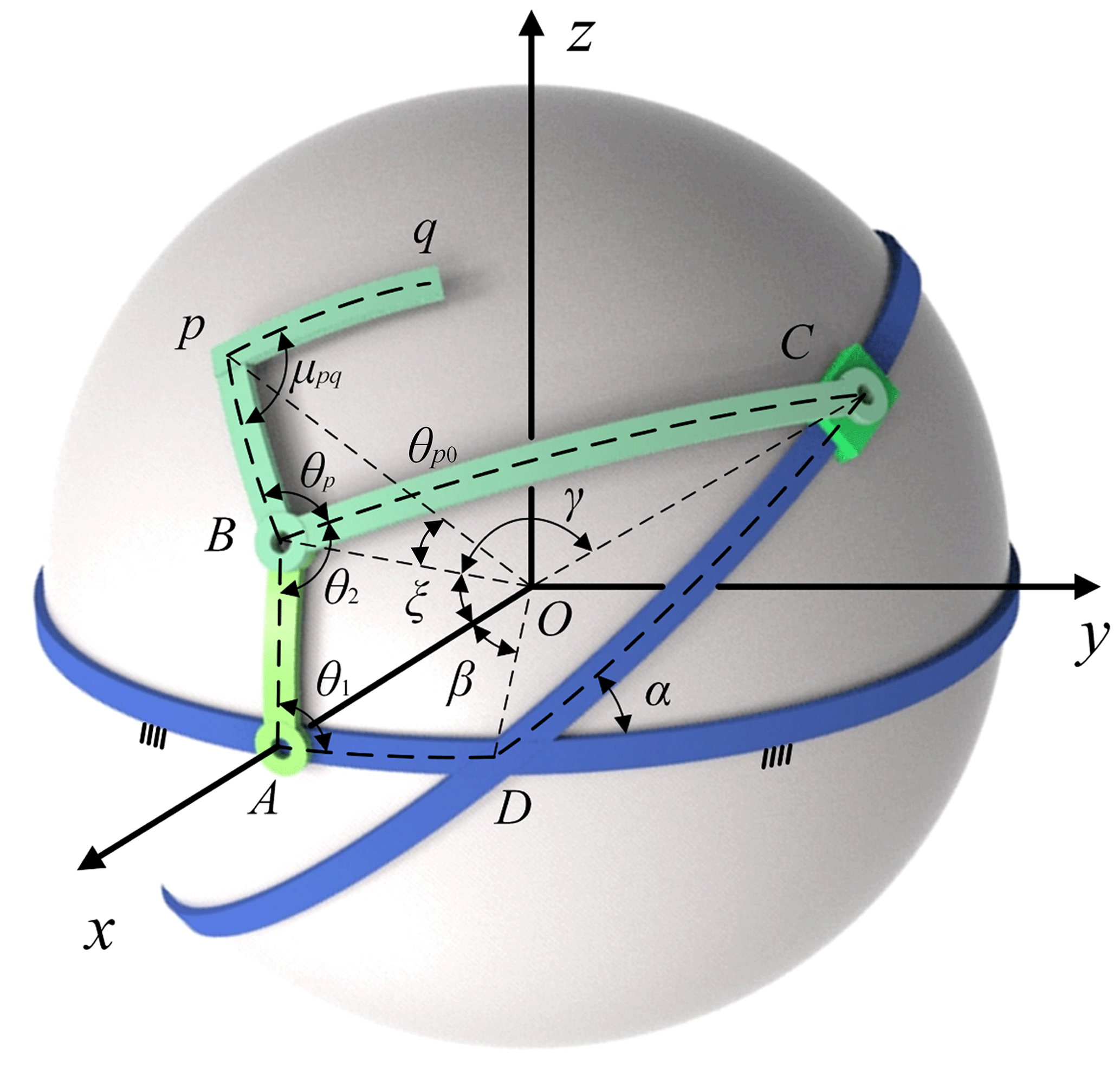
Motion generation or rigid-body guidance synthesis aims to obtain a series of prescribed rigid-body poses, which involves quantitative or qualitative design. There are two parts (orientation and position of rigid body) involved in the rigid-body guidance-line output of linkage mechanisms. As shown in Fig. 1, the spherical arc pq represents the output of mechanism, θpq denotes the corresponding central angle, and μi refers to the orientation of the ith rigid-body pose.

2.1 The mathematical model of the rigid-body output
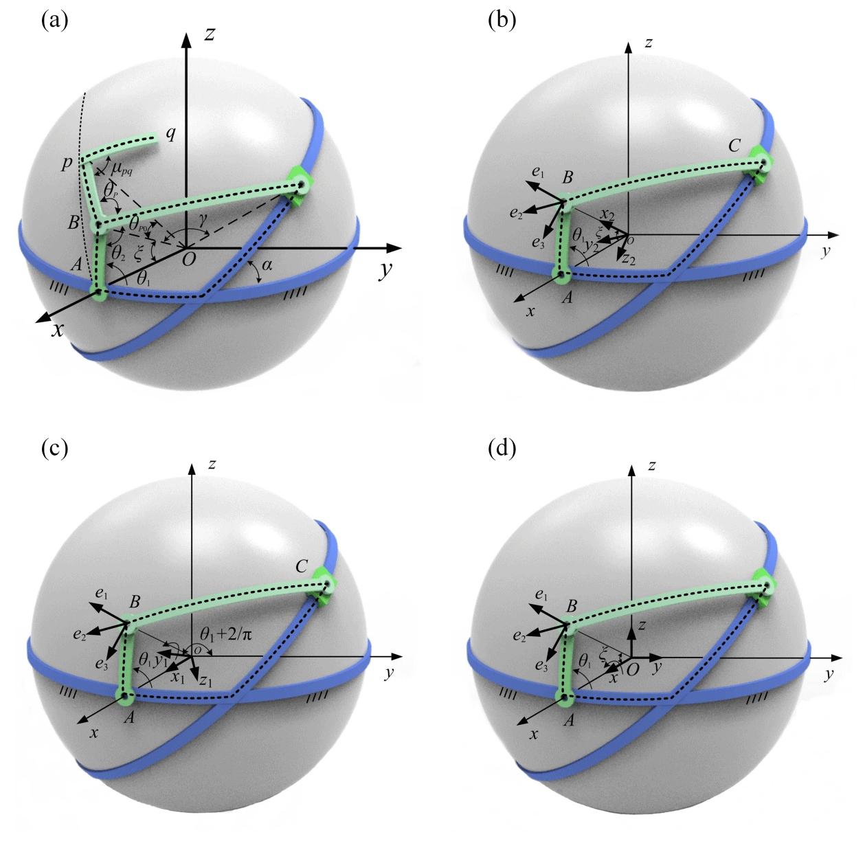
Figure 2 shows the geometrical model of mechanism in the Cartesian coordinates O–xyz, and R indicates the radius. The axis of revolution of input link AB lies on the x axis, and the frame AD lies on the xOy plane. The angle of the arc Bp and arc pq is denoted as μpq, and the angle between Bp and BC is indicated by θp. θ2 represents the coupler angle. AB, BC, DA, and Bp denote central angles α, γ, ξ, θp0, respectively, where AB is input link, BC is the coupler, component C is a slider, and DA is the frame. As shown in Fig. 3, the coordinate B–e1e2e3 is established, where e1 coincides with OB, e2 represents the tangent vector of the path of point B, and . The coordinate B–e1e2e3 can be transformed into the global Cartesian coordinate O–xyz in two steps. Figure 3a shows that mechanism model, while Fig. 3b to d represents the two steps taken for the transformation of the coordinate system:
- 1.
As shown in Fig. 3b and c, the coordinate O–xyz rotates around the x axis, the rotation angle of which is . Then, the coordinate O–x1y1z1 can be obtained, while the relationship between the coordinate O–xyz and the coordinate O–x1y1z1 can be described as follows:
where .
- 2.
As shown in Fig. 3b and c, the (O, x1, y1, z1) rotates around the y1 axis, the rotation angle of which is α. The coordinate O–x2y2z2 can be obtained, while the relationship between the coordinate O–x1y1z1 and the coordinate O–x2y2z2 can be described as follows:
According to the above equations, the relationship between the coordinates B–e1e2e3 and O–xyz can be represented as follows:
where , Q represents the initial angle, ω indicates the fundamental frequency, and t refers to time.
The position of point p on e1, e2, and e3 can be expressed as
where and θ represents the input angle of the mechanism.
Therefore, the position of point p on the global coordinate O–xyz can be expressed as
By substituting Eqs. (7) to (12) into Eq. (13), it can be obtained that
For the convenience of description, a complex plane is established; the real axis lies on the y axis of the global coordinate, and the imaginary axis lies on the z axis of the global coordinate. Equation (14) can be expressed as
where .
The position of point p on the x axis (rpx(t)) can be expressed as
Similarly, the projection of the position of point p on the yOz plane (rpyz(t)) can be expressed as
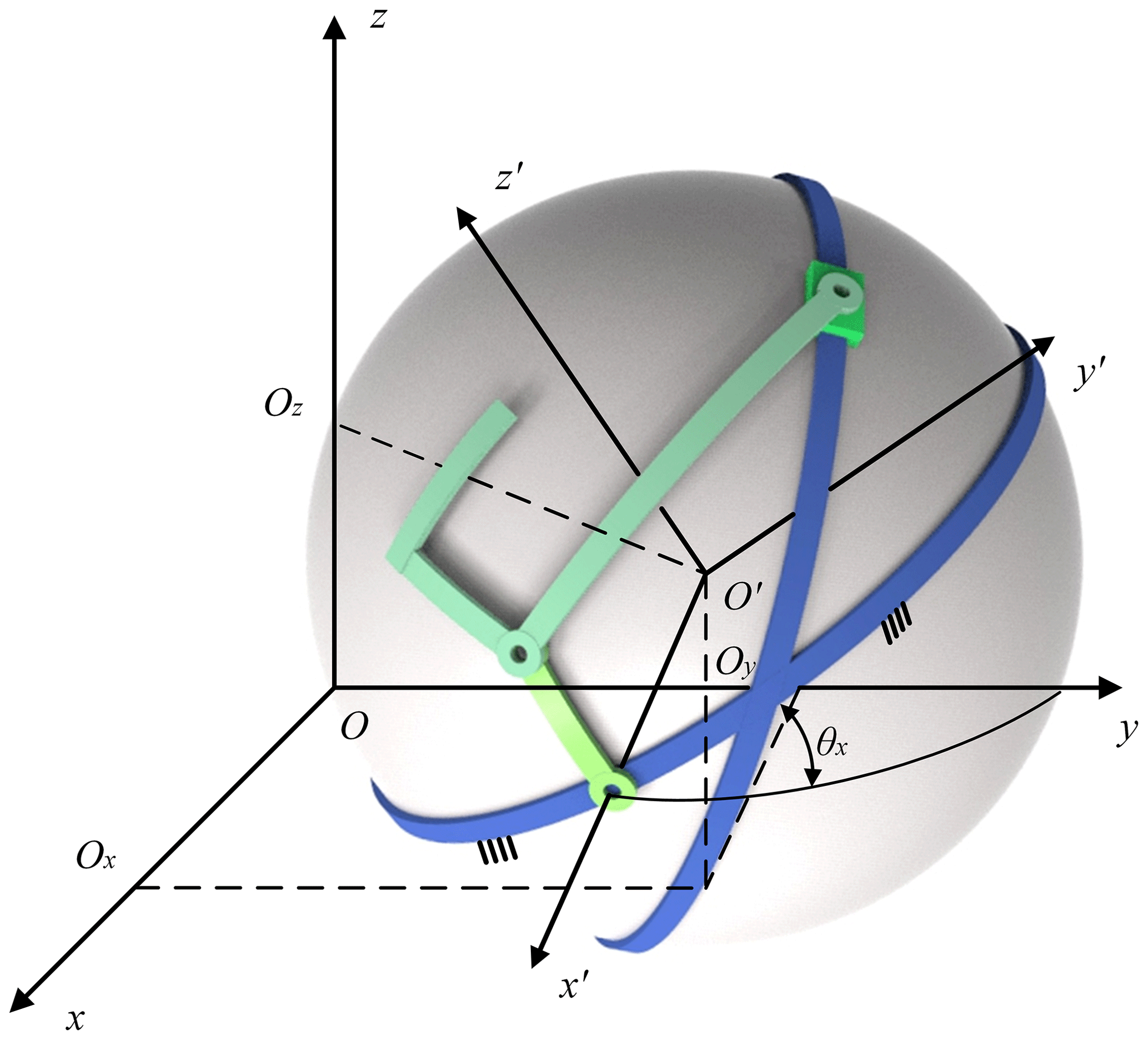
Figure 4 shows the spherical mechanism in a general position of installation. The translation and rotation of the frame can be described by Ox, Oy, Oz, and θx, while the initial angle of the input link is denoted as Q. Based on Eq. (16), the projection on the x axis of point p can be expressed as
where .
According to Eq. (17), the projection of the position of point p on the yOz plane can be expressed as as follows:
Therefore, the position of point p of the mechanism in a general installation position can be represented by Eqs. (18) and (19).
2.2 The preprocessing method of rigid-body markings
In the previous work, the dimensional synthesis of the spherical four-bar slider crank mechanism was studied, and a numerical atlas method was proposed to identify the basic dimensional types of the mechanism. Besides this, the output of the linkage mechanism was described by harmonic parameters, and the design results were obtained by comparing the prescribed design requirements with that in the numerical atlas database. However, the feature parameter extraction algorithm restricts the proposed method into solving only the rigid-body guidance synthesis of spherical linkage mechanisms in particular positions, where the rotation axis of the input component is parallel to the x axis of the global coordinate system and the plane of the frame is parallel to the xOy plane. For the spatial RRSS mechanism in a general installation position, this method is not applicable to obtain high-precision results. Therefore, a method is proposed in this paper to eliminate the impact caused by the rotation of the frame around the y axis and the z axis on the feature parameter of the trajectory curve.
As shown in Fig. 5, O–xyz is the global coordinate system. The requirements of the given design are detailed in Fig. 5a. The red solid line represents the output curve of the point p position, the solid blue line indicates the output curve of the point q position, and the black solid line between these two curves refers to the required rigid-body guidance line. According to the formula of the centroid of a curve, the centroid Q of the trajectory can be expressed as
where, QX, QY, and QZ represent the x, y, and z axes of the centroid Q, respectively; xQ, yQ, and zQ indicate the parametric equation of any curve, respectively; ; and ρ denotes the density function of coordinate parameter S.
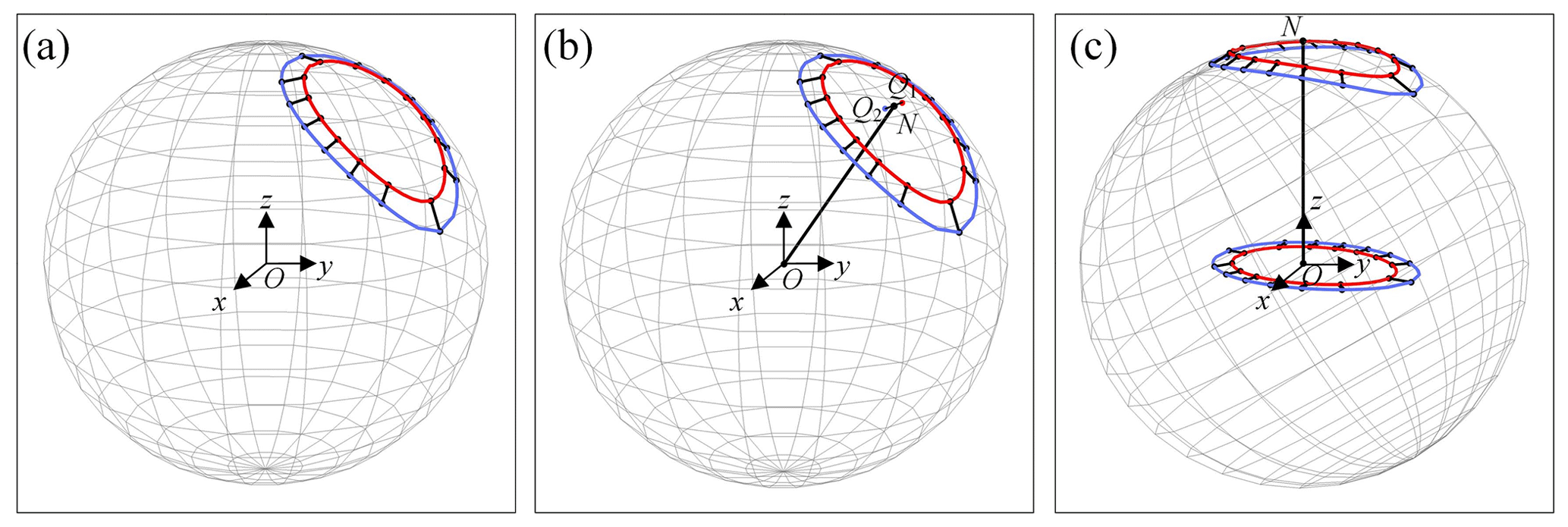
Then, it is possible to calculate Q1 and Q2, which are, respectively, the centroid of the output curve of the point p position and the output curve of the point q position. The midpoint N (Nx, Ny, Nz) of Q1Q2 can be expressed as
As shown in Fig. 5b, point O is connected with point N, and a straight line ON is defined as the central axis. In this paper, the normalization method is used to rotate the output curve of the point p position and the output curve of the point q position around the x axis simultaneously. The rotation angle ηy, ηz can be expressed as
Now, the central axis ON lies in the z axis. As shown in Fig. 5c, the output curve of the point p position and the output curve of the point q position on the xOy plane can be projected.
Through rotation and transformation, the above method is used to eliminate the influence rotation of the frame around the y axis and the z axis on the feature parameter of the trajectory curve. It enables the Fourier transform to extract the feature information from the output curve of a spherical four-bar mechanism in a general position of installation.
From Fig. 6, we can get the orientation output as follows:
From the geometric relationship of spherical trigonometry, the following relations between μp and θ2 can be known:
By substituting Eq. (29) into Eq. (28), the orientation of the arc pq can be obtained as follows:
The angular velocity of the input crank AB is expressed as ω (θ1=ωt), and Eq. (30) is expressed as
Similarly, according to Eq. (31), the orientation output of the mechanism in a general position of installation can be expressed as
Therefore, the position output and orientation output can be expressed as Eqs. (18), (19), and (32), respectively.
3.1 Fourier series expression of the output
According to Fourier series theory, the function of cos (θ2(t)+θp) can be expressed as
where cn and ϕn represent the amplitude and the phase angle, respectively.
Similarly, when the initial angle is denoted as Q, Eq. (32) can be rewritten as
As , Eq. (34) can be written as
By substituting Eq. (35) into Eq. (18), the position output of the mechanism as studied here and projected on the x axis can be expressed as
The n=0 item of Eq. (36) is merged as follows:
Similarly, the function of can be expressed as
where and represent the amplitude and the phase angle, respectively.
When the initial angle is indicated by Q, Eq. (38) can be expressed as
As , Eq. (39) can be expressed as
By substituting Eq. (40) into Eq. (19), the position output of the mechanism studied here and projected on the yOz plane is expressed as
By merging +1 item (m=0) in Eq. (41), it can be obtained that
By merging 0 item () of Eq. (42) and defining , it can be obtained that
Thus, the harmonic components of the position output are expressed as Eqs. (37) and (43).
According to Eq. (29), the Fourier series expansion of μp(t) is defined as
where and refer to the amplitude and the phase angle, respectively.
If the initial angle of the crank AB is Q (, Eq. (44) is expressed as
As , Eq. (45) is rearranged. Therefore,
By substituting Eq. (46) into Eq. (32) and merging the item, the orientation output of the mechanism is expressed as
3.2 The extraction of the output characteristic parameters
Apparently Eqs. (33), (38), and (44) are implicitly related to Eqs. (37), (43), and (47). After the normalization of Eqs. (33), (38), (44), (37), (43), and (47), different factors such as the actual size, initial angle, and Installation position are eliminated. Besides this, the general law of the harmonic component of the orientation output and the mechanism parameters is determined.
3.2.1 Define and extract the harmonic characteristic parameters of the position output
After dividing Eq. (33) by (the harmonic of the −1 term), it can be obtained that (cn is the nth term series of a 1D Fourier transform )
Similarly, after dividing Eq. (37) by (the harmonic of the −1 term), it can be obtained that
By comparing Eq. (48) with Eq. (49), it can be discovered that they have the same amplitude accordingly (except for item 0), the phase difference of which is (n+1)Q.
Similarly, after dividing Eq. (38) by ( is the nth term series of a 2D Fourier transform), it can be obtained that
Similarly, after dividing Eq. (43) by the (the term −1 harmonic), it can be obtained that
Comparing Eq. (50) with Eq. (51), it can be found that they have the same amplitude correspondingly (except for item 0 and +1), and the phase difference is .
By comparing Eq. (50) with Eq. (51), it can be found out that they have the same amplitude accordingly (except for item 0 and +1), the phase difference of which is .
Through the above analysis, the harmonic components of the position output are expressed by Eqs. (48) and (50) (except for individual items). Also, the function and are determined by the five parameters of the mechanism as studied here, including α, γ, ξ, α1, and θp. The amplitude of the output can be described by using parameters (α, γ, ξ, α1, and θp). Therefore, the parameters of α, γ, ξ, α1, and θp are defined as MPBDT (the mechanism's position of basic dimensional types), while harmonic components and are defined as a group of position of harmonic characteristic parameters' dimensional type (PHCPDT). The functions of and are defined as the rigid-body position operator (RBPO). On this basis, it can be found out that the RBPO is determined only by the MPBDT, rather than other factors such as the structural and arrangement parameters of the spherical four-bar crank slider rigid-body guidance mechanism.
3.2.2 The characteristic parameters of the orientation output
According to Eq. (31), the orientation output function μp(t) is a periodic function when the link AB is cranked, and the shift of the function curve affects only the initial angle and the average value. Therefore, the function can be obtained by the function μp(t), as shown in Fig. 7. By comparing Eq. (44) with Eq. (47), it can be discovered that they have the same amplitude, and the phase differences of both are nQ (except for 0 items). Thus, the characteristic parameter of the rigid-body orientation output can be described by using the amplitude () of the function μp(t). Herein, the amplitudes obtained from Eq. (44) are defined as the orientation of harmonic characteristic parameters' dimensional type (OHCPDT). Besides this, according to Eq. (29), the μp(t) is determined by the parameters α, γ, ξ, α1, θp, and θp0. The parameters of α, γ, ξ, α1, θp, and θp0 are defined as the orientation of basic dimensional types of the mechanism (MOBDT), while μp(t) is defined as the rigid-body orientation operator (RBOO). Through the above analysis, it can be discovered that the RBOO is determined only by the MOBDT, instead of other factors (such as the structural and arrangement parameters).
According to Eq. (47), the Fourier series ( is the amplitude of the nth harmonic component of a 3D Fourier transform, and are defined as the harmonic components of the prescribed orientation . Based on the property of the 1D Fourier transformation (∘ and ∘), the angle parameter μpq can be obtained as follows.
MOBDT involves all the parameters of MPBDT by comparing them. Thus, as the first step, a number atlas database of the orientation output is established by inputting both the OHCPDT and MOBDT. Then, fuzzy identification is performed to recognize several groups of MOBDT that satisfy the prescribed orientation output of the guidance mechanism as studied in this paper. Accordingly, a position problem of the rigid body can be transformed into a path generation problem when a reference point is chosen. According to Chu and Sun (2010), the characteristic parameters of both the design conditions and the MPBDT can be obtained by taking advantage of a fast Fourier transform (FFT). Subsequently, the actual length size and installation parameters can be calculated according to those parameters and theoretical formulas of the guiding mechanism as studied in this paper.
3.3 Calculation of the actual dimensions and arrangement parameters
By comparing Eqs. (33) and (38) with (37) and (43), respectively, the relationship between the amplitudes and phase angles can be determined, to derive the theoretical formulas about actual installation size, coupler point position, and installation size parameters. In this paper, the prescribed position rp on the x axis and yOz plane is defined as
where Dn represents the amplitude of the nth harmonic component of a 1D Fourier transform, indicates the amplitude of the nth harmonic component of a 2D Fourier transform, ζn denotes the initial phase of the nth harmonic component of a 1D Fourier transform, and refers to the initial phase of the nth harmonic component of a 2D Fourier transform.
The harmonic component of the angular characteristic function of the rigid body is defined as
Therefore, the actual size and arrangement parameters can be calculated as follows:
- 1.
The actual dimension of the crank (α) is
The other dimensional types of γ, ξ, and α1 can be obtained according to the proportional coefficient.
- 2.
The initial angle Q:
- 3.
The rotation angle θx:
- 4.
The spherical radius of the mechanism:
where
- 5.
The central angle θp0:
- 6.
The translation distance Ox in the x axis:
- 7.
The translation distance Oy, Oz in the y and z axes:
Equations (53) to (60) can be applied to calculate the parameters of the actual installation size of the guidance mechanism, as studied by this paper, and the coupler point position and installation size.
Table 1Flowchart of the synthesis process.
4.1 The influence of each parameter of the MOBDT upon the output
It is widely known that the parameters of the MOBDT have different effects on the output of the rigid body. Firstly, one group of MOBDT is chosen to verify the influence of each parameter. By changing each parameter with the same variable Δρ (herein, Δρ=2), the changes of the output of the rigid body are indicated, as shown in Fig. 8. Figure 8a shows the output affected by α, Fig. 8b shows the output affected by γ, Fig. 8c shows the output affected by ξ, Fig. 8d shows the output affected by α1, Fig. 8e shows the output affected by θp, and Fig. 8f shows the output affected by θp0. According to the results, α, θp, and θp0 have the most significant impact on the output, followed by α1. The effect of γ and ξ is the least significant. The blue curve in the figure indicates the trajectory curve of a given set of sizes, and the red curve represents the trajectory curve obtained by changing each size.
4.2 Variable step size output properties database and matching
The step size of OHCPDT in the output properties database is denoted as λ0. It can be found out that the accuracy of matching is higher when the λ0 is reduced. However, the complexity of the database increases. Conversely, if λ0 is larger, the matching speed improves, but the accuracy is reduced. Therefore, to ensure the sufficient accuracy and speed of matching, different step sizes denoted as λ0 are given for the distinct parameter of MOBDT, and the step size of each parameter is chosen according to the analysis in Sect. 4.1. Then, a different step size digital atlas database can be established.
According to Chu and Sun (2010), the proper MOBDT can be obtained by the following equation:
where δ represents the similarity function, while and Tn denote the OHCPDT in the design conditions and in the output properties database, respectively.
Based on the fuzzy theory, the similarity function makes a survey of the comparability. and Tn become more comparable when δ is reduced. Based on Eq. (61), it is possible to obtain several groups of MOBDT of the guidance mechanism as studied in this paper. There are 10 groups chosen in this paper.
4.3 Optimization method
Genetic algorithms represent one of the most adaptive methods to simulate the process of biological evolution on a computer. Its solution to the optimization problem starts by randomly generating the initial population that meets the constraints. Each individual in the population is taken as the first solution to the problem. Then, the selection, proliferation, crossover, mutation, and other genetic operations are conducted. By eliminating the basic size function which is clearly different from the objective function, a smaller basic size function is retained, and a new population is obtained. The new group members have less error than the previous generation group, which is significantly better than the previous generation. Through this continuous breeding evolution, the genetic algorithm is used to optimize the target mechanism.
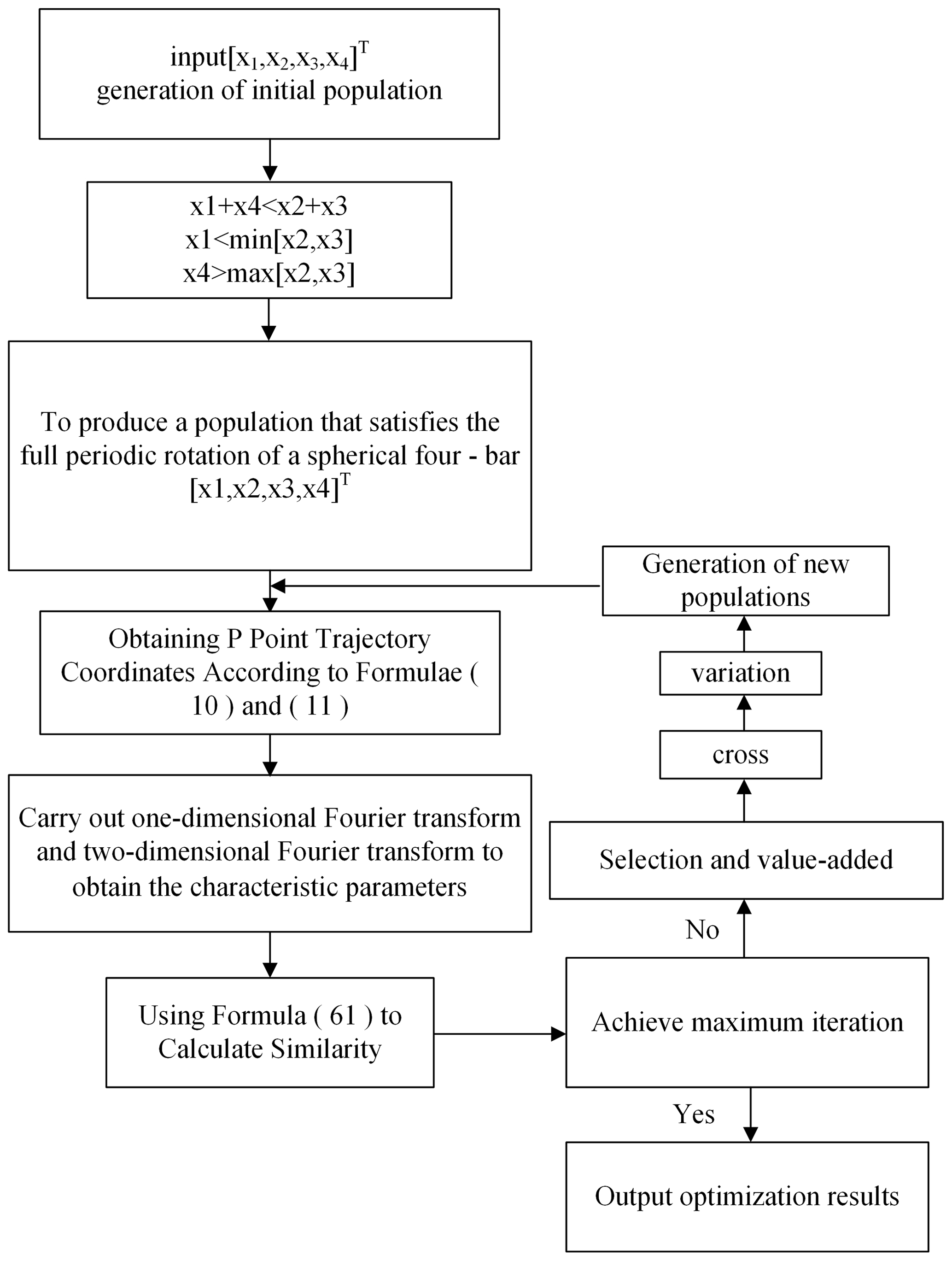
The main steps are as follows:
- 1.
Given the size type, frame length, two connecting rod lengths, and the crank length that need to be optimized, the initial population size rate, mutation rate, and maximum algebra are set. x is taken as the optimization variable.
where X represents the initial population; and x1, x2, x3, and x4 indicate the corresponding quantity of α, γ, ξ, and β.
- 2.
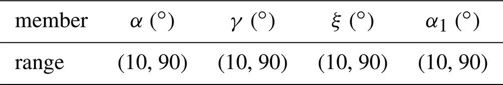
Given the constraints and range (the corresponding ranges are given in Table 2) of the spherical four-bar rigid-body guidance, the constraints are
- 3.
The size of the initial population of the spherical four-bar rigid-body guidance mechanism is set in random generation (Step 2).
- 4.
According to the above Eqs. (10) and (11), the position of the trajectory P point is determined for all the size types of the generated population.
- 5.
1D Fourier transform and 2D Fourier transform are performed on the solved p-point trajectory to extract the corresponding characteristic parameters.
- 6.
Equation (61) is used to calculate the similarity between the extracted characteristic parameters and the Fourier characteristic parameters of the objective function.
- 7.
All sizes are arranged in the order of similarity, and the individuals with low similarity replace the individuals with high similarity.
- 8.
Each of the two sizes forms a group and starts to cross-reproduce, with new sizes produced.
- 9.
The random selection of certain generations is performed for mutation.
- 10.
According to the results of Step (6), the similarity of all size types average, and the best individual similarities are expressed.
If the maximum algebra is reached, the optimization is terminated; otherwise, it returns to Step (4) to continue the optimization.
Taking into account the characteristics of the output objective function of the spherical four-bar rigid-body guidance mechanism, the genetic algorithm is used in this paper to optimize the mechanism, as shown in Fig. 9. The population size is 500, and the crossover probability is 0.8. The two-point crossover operator is used, and the geometric programming sorting selection is carried out. The number of genetic iterations is 200.
4.4 Illustration
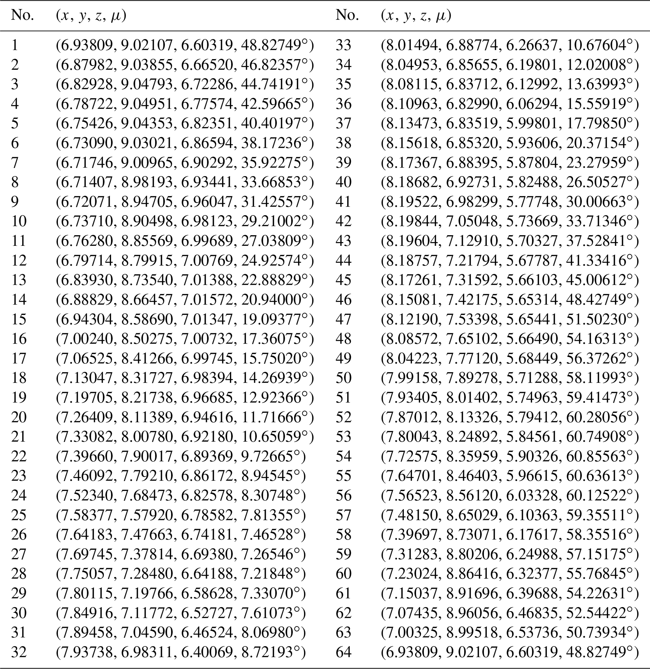
The design requirements and reference point p are shown in Fig. 10, and the coordinates of sampling points are given in Table 3. There are 64 points given in this paper, of which, eight points (which are in bold) are chosen to translate the position problem of the rigid body into a path generation one. It is supposed that a mechanism studied by this paper is synthesized into a given angle and position.


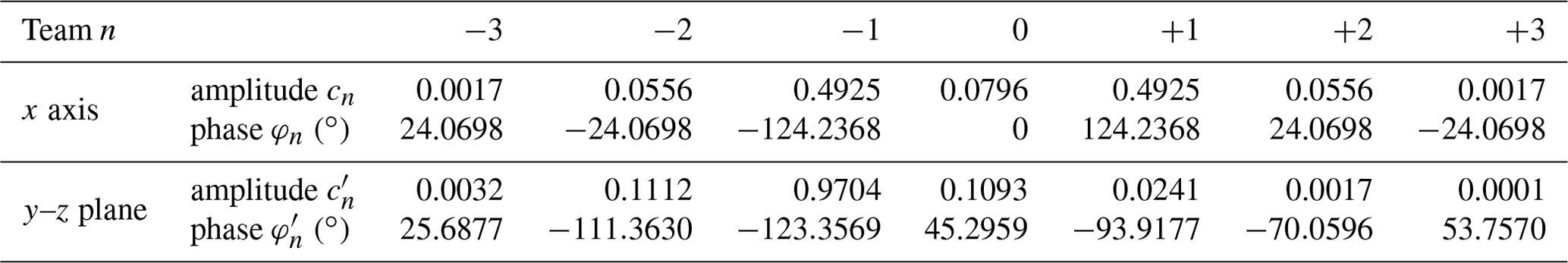
Based on the above analysis, a variable step size output properties database of the mechanism is first established. Through a 1D FFT and normalization process, the OHCPDT of the design requirements can be extracted. Table 4 shows four terms of amplitudes of the prescribed orientation. The matching method is used to identify 10 groups of the MOBDT from the database. According to each group of the MOBDT, we establish the initial population, so as to obtain the MOBDT of the desired mechanism, as shown in Table 5. Then, Eq. (52) is applied to obtain the actual dimensions of the μpq, as shown in Table 7. Table 6 shows the harmonic components of the prescribed position, and Table 8 shows the harmonic components of the RBPO as obtained through FFT. Table 7 lists the dimension parameters and installation parameters as obtained by Eqs. (53) to (60).

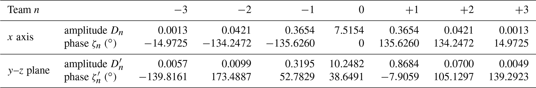
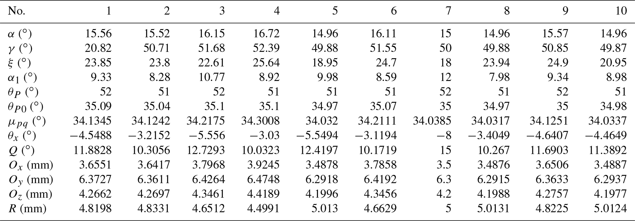
Table 8The amplitude and phase of the RBPO of the 10th group of the MPBDT.
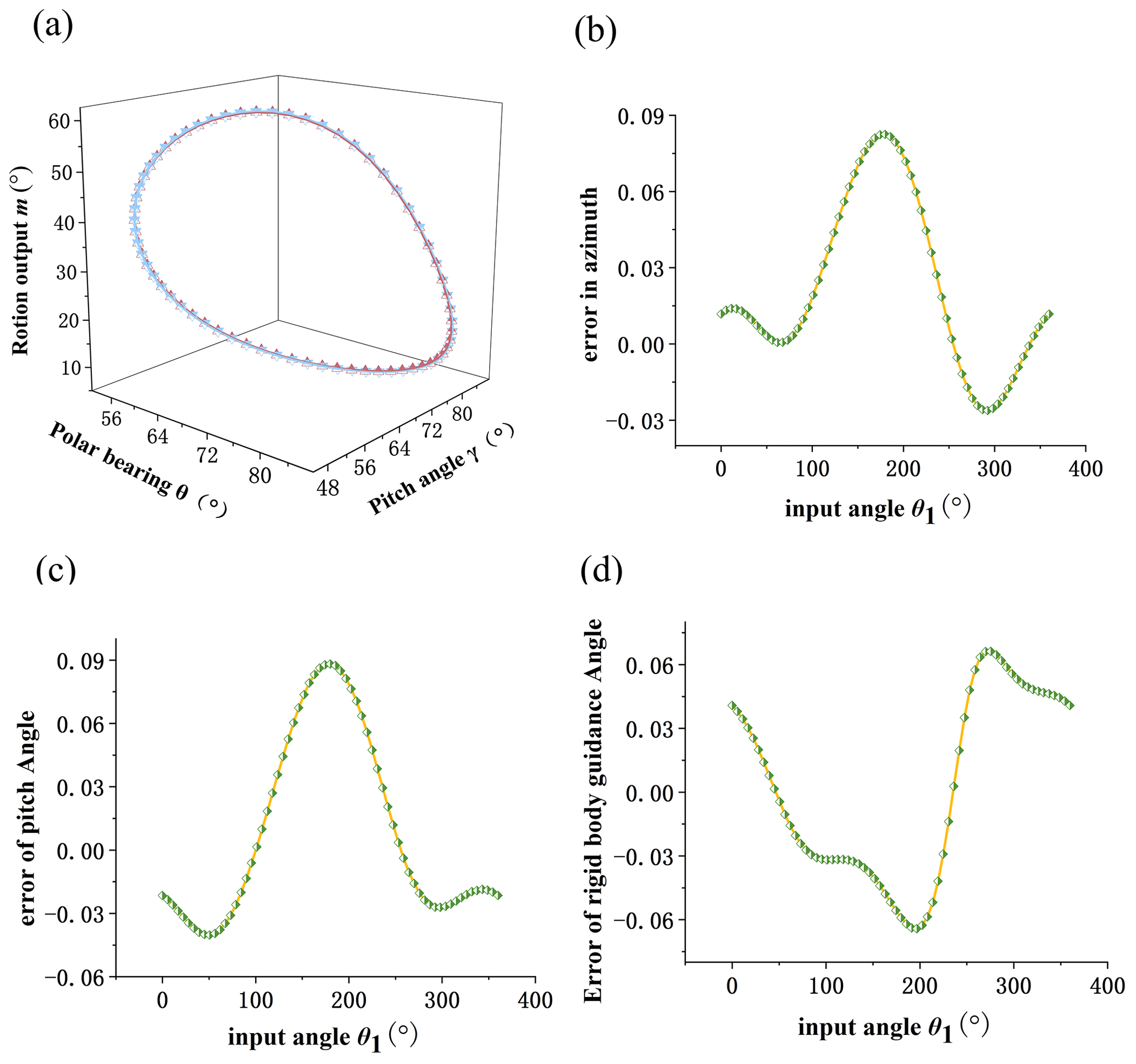
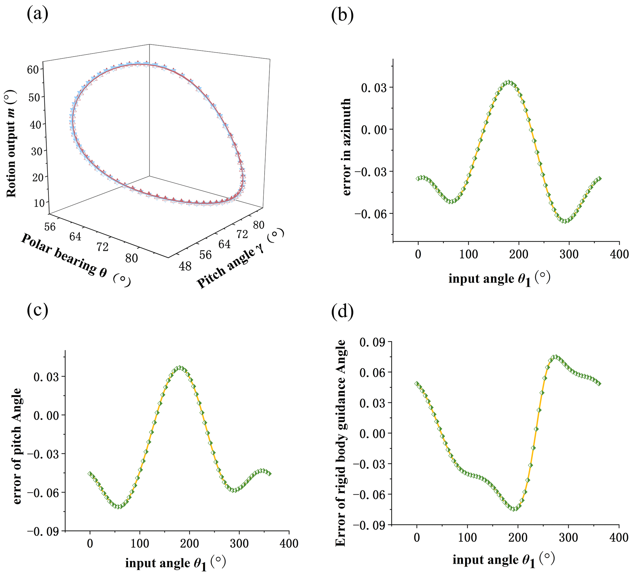
Finally, the comparison diagrams of three groups of design results and given design requirements are shown in Figs. 11, 12, and 13. The design requirements are shown in blue, and the design results are shown in red. It can be seen that the fitting curve overlaps completely. Part (b) in the figure is the comprehensive result error in azimuth. Part (c) in the figure is the comprehensive result error of the pitch angle. Part (d) in the figure is the comprehensive result error in the rigid-body guidance angle.

- 1.
A new method is proposed to address the motion generation problem of spherical four-bar crank slider rigid-body guidance mechanisms. According to the corresponding parameters of the position output and direction output of the research institutions in this paper, a method is developed to establish the output properties database of the mechanism. Then, the solution to the dimension parameters is proposed as well. By using the output properties database and the solution method, motion generation is achieved.
- 2.
The analytical methods are applicable only to deal with the problem of finitely divided positions. However, the method proposed in this paper can be used to effectively solve the problem of motion generation with infinite prescribed positions in theory. Through comparison with analytical methods, nonlinear equations are avoided in this paper, which makes the method much more efficient and simple.
- 3.
The method combines the advantages of the analytical method and the atlas method characterized by precision and simple calculation. Through a computer, it is achievable to quickly and accurately identify various groups of OHCPDT which meet the design requirements. Besides this, the dimension and installation parameters can be calculated as well, with several optimal options available to users. At last, this method can be extended to the motion generation of other types of linkage mechanisms, such as a spherical four-bar mechanism and RCCC mechanisms.
The code is available upon request from the corresponding author.
The data are available upon request from the corresponding author.
All the authors contributed to the study conception and design. The mathematical model and design method were proposed by JS and WL, experimental design and analysis were performed by ZL and HL. The first draft of the paper was written by WZ, ZL and WL. All the authors commented on previous versions of the paper. All the authors read and approved the final paper.
The contact author has declared that none of the authors has any competing interests.
Publisher’s note: Copernicus Publications remains neutral with regard to jurisdictional claims in published maps and institutional affiliations.
The authors acknowledge financial support from the National Natural Science Foundation of China, Hubei Provincial Natural Science Foundation of China, the Science and Technology Research Project of the Jilin Provincial Department of Education, Central Government Guides Local Science and Technology Development Projects of Hubei Province, and Science and Technology Innovation Team of Hubei University of Arts and Science.
This research has been supported by the National Natural Science Foundation of China (grant no. 51775054), Hubei Provincial Natural Science Foundation of China (grant no. 2022CFC035), the Science and Technology Research Project of the Jilin Provincial Department of Education (grant no. JJKH20220672KJ), Central Government Guides Local Science and Technology Development Projects of Hubei Province (grant no. 2018ZYYD016), and Science and Technology Innovation Team of Hubei University of Arts and Science (grant no. 2022pytd01).
This paper was edited by Daniel Condurache and reviewed by five anonymous referees.
Alizade, R., Can, F. C., and Kilit, Ö.: Least square approximate motion generation synthesis of spherical linkages by using Chebyshev and equal spacing, Mech. Mach. Theory, 61, 123–135, https://doi.org/10.1016/j.mechmachtheory.2012.10.009, 2013.
Avilés, R., Navalpotro, S., Amezua, E., and Hernández, A.: An energy-based general method for the optimum synthesis of mechanisms, J. Mech. Des.-T. ASME, 116, 127–136, https://doi.org/10.1115/1.2919336, 1994.
Bagci, C.: Geometric methods for the synthesis of spherical mechanisms for the generation of functions, paths and rigid-body positions using conformal projections, Mech. Mach. Theory, 19, 113–127, https://doi.org/10.1016/0094-114X(84)90013-2, 1984.
Chu, J. and Sun, J.: Numerical atlas method for path generation of spherical four-bar mechanism, Mech. Mach. Theory, 45, 867–879, https://doi.org/10.1016/j.mechmachtheory.2009.12.005, 2010.
Chu, J. K. and Cao, W. P.: Synthesis of coupler curves of planar four-bar linkages through fast Fourier transform, Chin. J. Mech. Eng., 29, 117–122, 1993.
Hayes, M. and Zsombor-Murrary, P.: Towards Integrated Type and Dimensional Synthesis of Mechanisms for Rigid Body Guidance, in: Proceedings of the CSME Forum 2004, London, ON, Canada, June 2004, 53–61, https://citeseerx.ist.psu.edu/document?repid=rep1&type=pdf&doi=b39ebfd25b72b39e3388efac3107cad7aa85ae63 (last access: 26 February 2023), 2004.
Lee, W. T. and Russell, K.: On two-phase spherical motion generation, J. Chinese Soc. Mech. Eng. Trans., 28, 617–622, https://doi.org/10.29979/JCSME.200712.0008, 2007.
Lee, W. T., Russell, K., Shen, Q., and Sodhi, R. S.: On adjustable spherical four-bar motion generation for expanded prescribed positions, Mech. Mach. Theory, 44, 247–254, https://doi.org/10.1016/j.mechmachtheory.2008.01.008, 2009.
Li, L. and Chen, Y.: Application of Buchberger Algorithm in the synthesis of planar rigid-body guidance, J. Mech. Sci. Technol., 15, 211–215, 1996.
Lin, W. Y.: Optimum path synthesis of a geared five-bar mechanism, Adv. Mech. Eng., 5, 757935, https://doi.org/10.1155/2013/757935, 2013.
Liu, W. R., Zhao, Y., Qin, T., Li, B., Wang, C., and Sun, J. W.: Optimal synthesis of a spatial RRSS mechanism for path generation, Meccanica, 58, 255–285, https://doi.org/10.1007/s11012-022-01616-3, 2023.
Meyer zur Capellen, W.: Kinematik und Dynamik der Kurbelschleife, Werkstatt und Betrieb, 10, 581–584, 1956.
Mullineux, G.: Atlas of spherical four-bar mechanisms, Mech. Mach. Theory, 46, 1811–1823, https://doi.org/10.1016/j.mechmachtheory.2011.06.001, 2011.
Myszka, D. H. and Murray, A. P.: Pole arrangements that introduce prismatic joints into the design space of four- and five-position rigid-body synthesis, Mech. Mach. Theory, 45, 1314–1325, https://doi.org/10.1016/j.mechmachtheory.2010.04.001, 2010.
Peñuñuri, F., Peón-Escalante, R., Villanueva, C., and Pech-Oy, D.: Synthesis of mechanisms for single and hybrid tasks using differential evolution, Mech. Mach. Theory, 46, 1335–1349, https://doi.org/10.1016/j.mechmachtheory.2011.05.013, 2011.
Russell, K. and Sodhi, R. S.: Kinematic synthesis of adjustable RRSS mechanisms for multi-phase motion generation, Mech. Mach. Theory, 36, 939–952, https://doi.org/10.1016/S0094-114X(01)00028-3, 2001.
Russell, K. and Sodhi, R. S.: Kinematic synthesis of RRSS mechanisms for multi-phase motion generation with tolerances, Mech. Mach. Theory, 37, 279–294, https://doi.org/10.1016/S0094-114X(01)00064-7, 2002.
Ruth, D. A. and McCarthy, J. M.: Design of spherical 4R linkages for four specified orientations, Mech. Mach. Theory, 34, 677–692, https://doi.org/10.1016/S0094-114X(98)00048-2, 1999.
Shirazi, K. H.: Computer modelling and geometric construction for four-point synthesis of 4R spherical linkages, Appl. Math. Model., 31, 1874–1888, https://doi.org/10.1016/j.apm.2006.06.013, 2007.
Sun, J. W. and Chu, J. K.: Fourier method to function synthesis of an RCCC, P. I. Mech. Eng. C-J. Mec., 223, 503–513, https://doi.org/10.1243/09544062JMES1091, 2008.
Sun, J. W. and Chu, J. K.: Fourier series representation of the coupler curves of spatial linkages, Appl. Math. Model., 34, 1396–1403, https://doi.org/10.1016/j.apm.2009.08.030, 2010.
Sun, J. W., Chu, J. K., and Sun, B. Y.: A unified model of harmonic characteristic parameter method for dimensional synthesis of linkage mechanism, Appl. Math. Model., 36, 6001–6010, https://doi.org/10.1016/j.apm.2012.01.052, 2012.
Wei, N., Sun, H., Jia, Q., Ji, X., and Shi, H.: Analysis and design optimization of a compact and lightweight joint torque sensor for space manipulators, Adv. Mech. Eng., 5, 241384, https://doi.org/10.1155/2013/241384, 2013.
Yoon, G. H. and Heo, J. C.: Constraint force design method for topology optimization of planar rigid-body mechanisms, Comput. Aided Design, 44, 1277–1296, https://doi.org/10.1016/j.cad.2012.07.005, 2012.
Yu, H. Y., Tang, D. W., and Wang, Z. X.: Study on a new computer path synthesis method of a four-bar linkage, Mech. Mach. Theory, 42, 383–392, https://doi.org/10.1016/j.mechmachtheory.2006.05.003, 2007.
Wang, Z. X., Yu, H. Y., Tang, D. W., and Li, J. S.: Study on rigid-body guidance synthesis of planar linkage, Mech. Mach. Theory, 37, 673–684, https://doi.org/10.1016/S0094-114X(02)00014-9, 2002.