the Creative Commons Attribution 4.0 License.
the Creative Commons Attribution 4.0 License.
 | 13 Mar 2023
A versatile end effector for grabbing and spreading of flaky deformable object manipulation
Yuan Huan
Gongchang Ren
Xiangyu Su
Weizhi Tian
It is a conundrum to use robots to complete the intelligent operation of leather and clothing fabrics; this is mainly reflected in the design of an end effector that can realize this function. We have determined the design requirements and objectives of the end effector by observing the action of manually grabbing and spreading leather, and put forward an end effector composed of a reconfigurable multi-link mechanism and roller-type fingertip, which can be used to grab and spread flaky deformable object manipulation. At the same time, the reconfigurable multi-link mechanism and roller-type fingertip are introduced and analyzed in detail. By setting up the prototype of the end effector and completing the grabbing experiment of three kinds of soft pieces, we verified and tested the rationality of the prototype design. The result shows that the grabbing success rate will be affected by many factors, and further exploration is needed to further improve the performance of the end effector.
- Article
(9187 KB) - Full-text XML
- BibTeX
- EndNote


As the computer and automation technology develops, many scholars have developed various robots to replace human beings to complete the work since the mid-20th century. At present, manual operation is still the main situation in the leather manufacturing and clothing industry. Specially in the harsh working conditions of the former, the leather handling and spreading operation between various processes not only needs a lot of labor but is also hard work. With the increasing shortage of labor force in recent years, it is particularly urgent to promote intelligent manufacturing in the leather and clothing industry. The key to realizing that lies in the intelligent operation of flaky deformable object manipulation such as leather, textile and other clothing fabrics. However, it is difficult to realize automatic operation due to the characteristics of flaky deformable object manipulation, such as a thin, large flat area and changeable shape (Jiménez, 2017). Therefore, the research on the operation of end effector with flaky deformable object manipulation is still a frontier problem in the field of robot technology (Donaire et al., 2020).
Many scholars have done a lot of research on end effectors for flaky deformable object manipulation. For example, Von Drigalski et al. (2017) grabbed textiles and adjusted the grabbing position by adding two 3D force sensors at the fingertips of the two-finger gripper. Koustoumpardis et al. (2018) grabbed the fabric by driving three fingers through the cam mechanism, which can increase the grabbing reliability and efficiency compared with the traditional two-finger gripper. The multifunctional gripper designed by Donaire et al. (2020) can pick and fold clothes by changing the friction force of the contact surface and adjusting the degree of freedom of the gripper. Yamazaki and Abe (2021) realized the grabbing and releasing of cotton fabric through two sets of cylindrical brushes. Corinaldi et al. (2015) transported the leather that was spread and accumulated on the beam by using the gripper designed and combining the four-bar mechanism with the negative pressure suction cup. Doulgeri and Fahantidis (2002) increased the grabbing reliability by adding a manipulator designed with a local degree of freedom at the fingertip and combining the fingertip which can rotate locally. For the handling of leather or cloth in a completely spread state, many scholars have designed various end effectors that use mechanical action (Koustoumpardis et al., 2014; Okada and Kanade, 1984; Hanafusa and Asada, 1977; Jacobsen et al., 1984), air pressure action (Mantriota, 2007; Failli and Dini, 2004; Betemps et al., 1991), electric field action (Sun and Zhang, 2019), materials or microstructure (Lee et al., 2019; Glick et al., 2018), etc. The abovementioned end effectors can realize partial operation on the flaky deformable object manipulation in a particular state, for example, the suction-type end effector can only grab the flaky deformable object manipulation and the claw-type end effector can only grab the corner parts of the flaky deformable object manipulation. In actual working conditions, the flaky deformable object manipulation will take on various states due to external forces such as random stacking or tiled stacking. For grabbing and spreading the flaky deformable object manipulation in different states, the abovementioned end effectors cannot meet the use requirements.
After studying the grabbing-and-spreading process of geometric soft fabrics in various forms, this paper analyzes the specific technological actions according to the technological process of manually operating leather. According to each technical logical action, an end effector based on the combination of a reconfigurable multi-link mechanism and roller fingertip structure is designed. Through its 3D modeling, kinematics analysis and simulation, combined with the grabbing and spreading experiments of its experimental prototype, it is verified that this end effector can be used for grabbing and spreading geometric soft fabrics.
The main contributions of this design are as follows.
-
Through the detailed analysis of the procedure of leather processing, the specific process actions of leather operation are defined, which provides the basis for the follow-up work.
-
A reconfigurable multi-link mechanism is designed, and the roller-type fingertip linear flat clamping and clamping process is realized by the combination of the Hoecken linkage and parallelogram mechanism.
-
Through the experiment, the influencing factors of the end effector's successful grabbing were found, which provided a clear direction for the further improvement of the end effector.
2.1 The analysis of leather grabbing and spreading
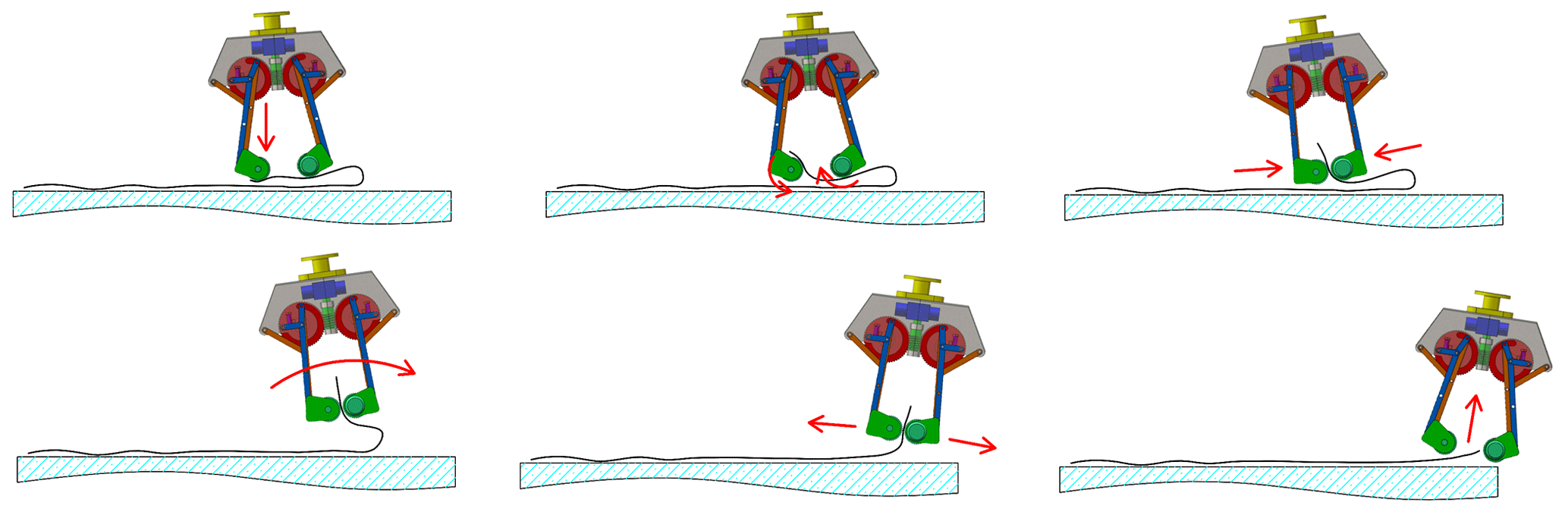
To meet the technical requirements of the end effector for grabbing and spreading flaky deformable object manipulation in any state, this paper takes leather as the research object, analyzes the manual operation process of leather in various states in combination with the actual working conditions, and obtains the design requirements of the end effector. The processing from raw leather to finished leather includes a number of physical and chemical processes. Currently, the leather is carried and spread manually between each process, and the whole process involved is shown in Fig. 1.
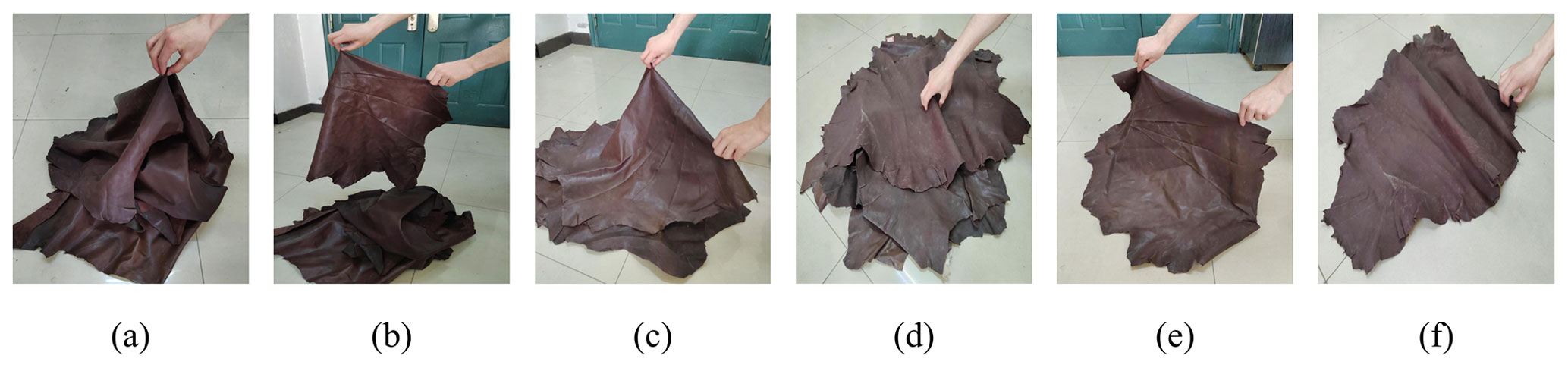
Figure 1Example of the grab-and-spread action. (a) Grab and lift the leather through the leather bulge or edge part for the leather in the wound and stacked state. (b) Stretch the edge of the leather with both hands, and make the leather flat in a large area under the action of gravity. (c) Lay the leather flat and stacked. (d) Grab the top layer of leather in a multi-layer tiled stacked state. (e) Lay the single-layer leather flat. (f) Grab the leather edge for stretching and spreading.
2.2 The analysis of grabbing process of multi-layer tiled state
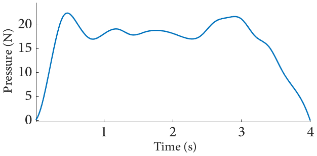
According to the analysis of the leather grabbing-and-spreading action combined with the shortcomings of various existing end effectors, it is found that the design difficulty of the end effector lies in how to grab the leather in the state of multi-layer stacking and laying, and at the same time ensuring that only a single sheet of leather is grabbed without affecting the second layer of leather. After a series of grabbing experiments were carried out by simulating workers' hands to grab leather in a multi-layer stacking and spreading state, it was found that reasonable control of the downforce on leather during the grabbing process is the key to ensure successful grabbing. By placing the multi-layer leather on the force-measuring platform, the change curve of the downforce during the test grabbing process after several successful grabs is shown in Fig. 2. In the process of grabbing, the finger should move at a constant speed and keep the downforce on the leather unchanged when the leather is gathered to the center. When the clamping force is applied to grab, a certain pressing force will be added to ensure that the leather gathered to the center keeps the convex state to ensure the reliability of grabbing. Finally, the clamping force is formed at the convex part of the leather to finish the successful grabbing of the leather. The change trend of the downforce obtained in the whole grabbing process is similar to that of Ono and Kunikatsu (2007) when grabbing multi-layer flat fabrics. Therefore, the key to successful grabbing is to keep a similar downforce trend when grabbing flaky deformable object manipulation in the multi-layer flat state.
2.3 The design requirements of end effector
After the analysis of the whole leather grabbing-and-spreading process, the design requirements for the end effector are as follows.
-
The folds or corners of the fabric can be grabbed, mainly to meet the grabbing and stretching actions of the edges and corners in the state of winding and stacking.
-
The adjustment of the grabbing position can be realized, mainly to meet the requirements of spreading the fabric when multiple manipulators work together in the actual application process.
-
The single-sheet grabbing operation of fabrics can be realized in the state of tiling and stacking. Especially when grabbing the fabric in the state of multi-layer stacking and tiling, the fingertip of the end effector should move at a constant speed to ensure the stability and reliability of the fabric converging to the center. Then, the fingertip has a local pressing action to ensure that the fabric is kept in a convex state when it is about to be grabbed. Finally, a clamping force is applied to the convex part of the fabric to achieve successful grabbing.
-
Because of the large flat area of the fabric, in order to ensure the reliability of the grabbing process and convenience, the end effector should have a large opening angle and a compact structure.
-
A reasonable mechanical structure should be used as far as possible to realize the demand. Considering that the actual working environment is rather harsh, it is difficult to realize the displacement compensation of the downforce generated in the grabbing process by relying on complex sensing and control systems.
3.1 The design and analysis of roller fingertips
According to the design requirements of the abovementioned end effector, various functions need to be met through the mutual cooperation of roller fingertips. The schematic diagram of the designed roller fingertip fit is shown in Fig. 3.

Figure 3Schematic diagram of roller fingertips cooperating with grabbing. (a) The rollers on both sides roll against each other and move to the center so that the center of the fabric in the multi-layer tiled state arches to realize the grabbing of the arched part. (b) When grabbing the corner of the fabric, the rotation speed of the roller near the edge is slightly higher, and the differential rotation of the two rollers makes the fabric at the edge bulge. After clamping the bulge, the roller continues to rotate at a differential speed, so that the roller near the edge transports all the fabric to the middle of the two rollers and finally clamps the corner of the fabric, making it convenient for the subsequent stretching operation. (c) The two rollers rotate reversely and move to both sides at the same time, and the fabric can be stretched to both sides by the friction of the rollers on the leather, thus achieving the spreading effect. (d) When grabbing and clamping the single-layer fabric, the grabbing position can be adjusted by rotating the two rollers at the same speed. (e) When grabbing fabric folds or clamping multi-layer fabrics, the grabbing position can be adjusted and the grabbing posture of leather can be changed partly by controlling the rotation direction and speed of the two rollers.
3.2 The design of reconfigurable multi-link mechanism
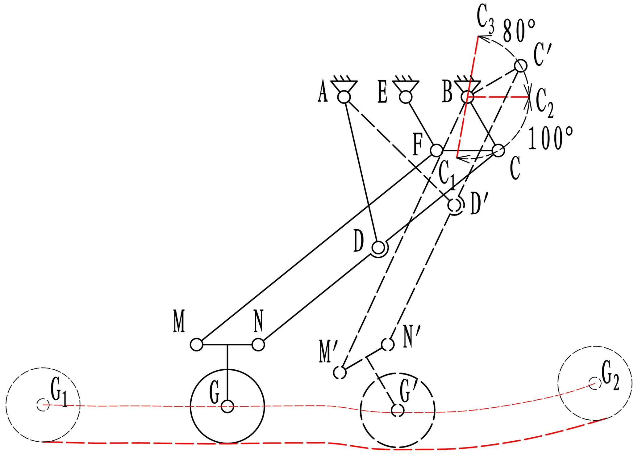
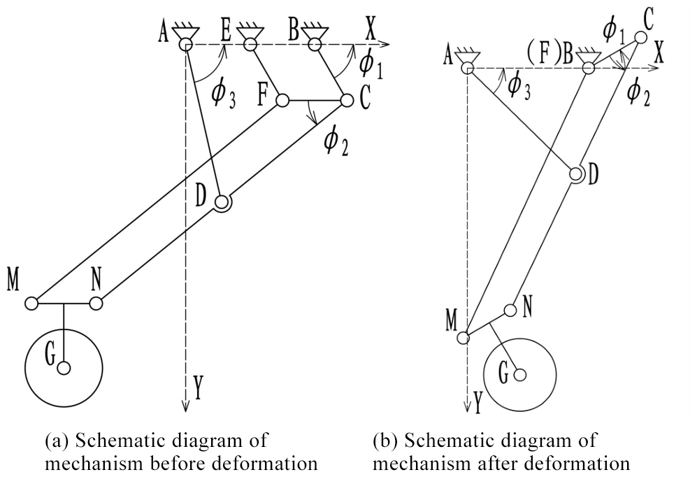
For better matching the roller fingertip to meet the design requirements of the end effector, a reconfigurable multi-link mechanism is designed in this paper. By combining the Hoecken linkage with the parallelogram mechanism, and skillfully using the dead-point position of the parallelogram mechanism to reconstruct the multi-link mechanism, the design requirements are met. The principle of the reconfigurable multi-link mechanism is shown in Fig. 4; here, the points indicated by letters are the hinges of the links, and the length of each link meets the following conditions:
where the link BC is the driving link, and the angle range is (100 to −80∘).
The whole grabbing process is divided into two stages. In the straight clamping stage (the driving link BC rotates from C1 to C2), the quadrilaterals EBFC and FCMN are parallelograms. Due to the constraint of the four-bar linear mechanism ABCDN, the movement trajectories of points M, N and G are straight lines, that is, the fingertip roller moves linearly on the surface of the fabric to push the fabric to converge toward the center. In the clamping stage (the link BC rotates from C2 to C3), the link EF is forced to stop rotating due to the action of the stop block, the link EF coincides with the link EB, the link FC coincides with the link BC, and the components of the multi-link mechanism turn to be parallelogram BC′ N′ M′ and four-bar mechanism ABC′ D′ N′. When the driving link BC rotates from C2 to C3, the point N′ continues to move linearly, and the point G′ which is the roller rotates around the point N′ while doing linear translation, expanding the vertical displacement and increasing the downforce on the leather to ensure that the fabric keeps the central convergence state. The link BC rotates until the rollers on both sides form a stable grabbing force on the fabric.
3.3 The structural design and modeling of the end effector
As shown in Fig. 5, the specific structure of the end effector designed according to the above mechanism includes components such as worm drive mechanism, linkage mechanism, fingertip roller, limiting block, return spring and housing. The worm gear, the link mechanism and the roller bracket together form a reconfigurable multi-link mechanism. The limit block is used to limit the rotation of the link EF to change the configuration of the multi-link mechanism. The return spring prevents the uncertainty of the movement of the manipulator when it passes through the dead point of the parallelogram linkage mechanism in the opening process. All components cooperate with each other to realize the function of grabbing and spreading the soft fabric of geometric figures.
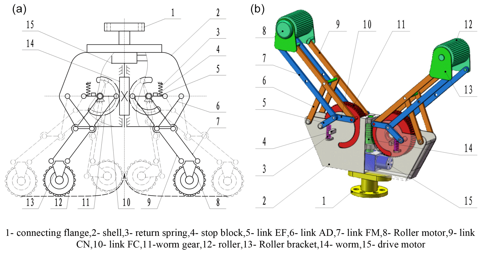
Figure 5The structure diagram of the end effector (a). The 3D model diagram of the end effector (b).
The end effector is provided with a connecting flange on the shell, which is convenient for the end effector to be installed on the mechanical arm. The driving motor is fixed inside the housing, and the link mechanism is driven by the worm gear transmission mechanism. When the driving motor is powered off, the self-locking characteristic of the worm gear can keep the clamping force and prevent accidents. Each link is hinged by pin shaft structure, and a limit block is arranged at the dead point of the link EF to prevent the uncertainty of the movement of the link EF at the dead point. A return spring is arranged at the position close to the dead point of the link EF to help the manipulator leave the dead point during the opening process.
The driving motor capable of controlling the rotation angle is arranged inside the fingertip roller. It can independently drive the two rollers to rotate, increase the local degree of freedom of the fingertips, and facilitate the end effector to adjust the grabbing position of the flaky deformable object manipulation and grab the flaky deformable object manipulation in the tiled state.
4.1 The kinematics analysis of the end effector
For further research on the changes of displacement, velocity and acceleration of the end effector during grabbing, as shown in Fig. 6, a reconfigurable multi-link kinematic model is established to analyze the movement process of the end effector.
The angle between link BC and the positive direction of the x axis is φ1, and the angles between link CD, AD and MN and the x axis are φ2, φ3 and φ4 respectively.
Based on the structural constraints, the change of φ4 is as follows:
For position analysis of the linkage mechanism, ABCD of the four-bar mechanism is regarded as a closed vector polygon, and the following results can be obtained:
Project Eq. (2) on the x axis and the y axis to obtain the following equation:
Rewrite Eq. (3) into the trigonometric equation:
In Eq. (4),
For convenience of algebraic method to solve φ3, make . The following can be obtained:
Turn it into a quadratic equation:
The solution of x is
φ5 is used to indicate the angle between the connecting line of NG two points and the x axis, and then the position in the center (G) of the roller is
In Eq. (9),
For the speed analysis of the moving roller, the time derivative of Eq. (9) can give the speed variation as follows:
The matrix expression of Eq. (10) is
in which Eq. (10) is
For the analysis of the acceleration of the roller, the time derivative of Eq. (10) can be used to obtain the analysis relation of the roller acceleration:
4.2 The kinematics simulation of end effector
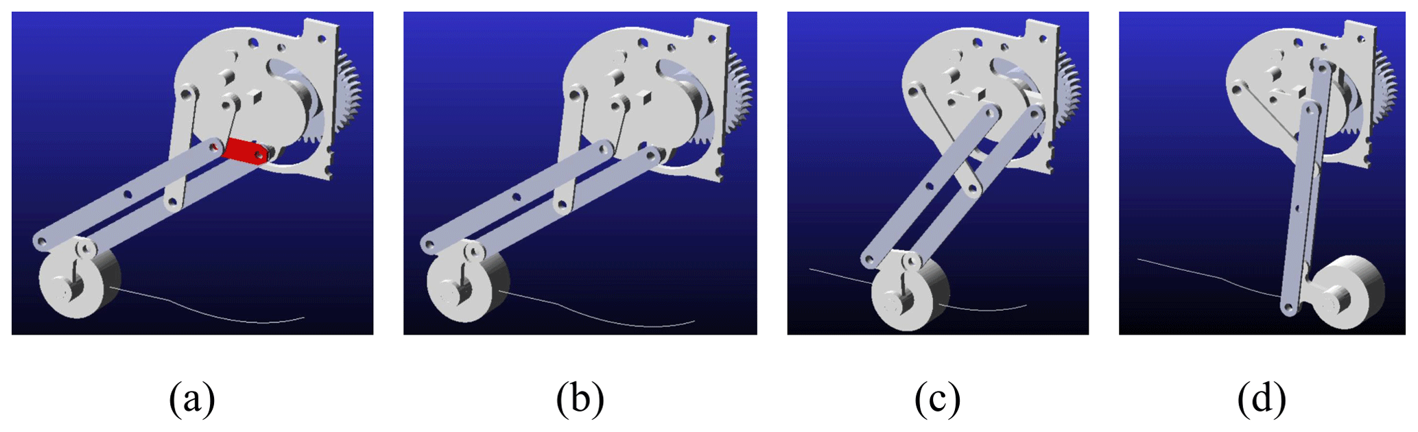
ADAMS was used to simulate the dynamics of the end effector. Since the end-effector structure is symmetrical from left to right, the unilateral mechanism is imported into ADAMS for kinematic simulation analysis in order to reduce computation. After the modeling is completed through SoildWorks, it is imported into ADAMS for necessary simplification and then the simulation time and step size are set. The simulation process is shown in Fig. 7. Considering that the connecting link is affected by the reset spring in the collision process with the limit block, in order to ensure the success and accuracy of simulation, the connecting link FC is flexibly treated, and the displacement, velocity and acceleration curves in the process of roller movement are obtained as shown in Figs. 8–10.
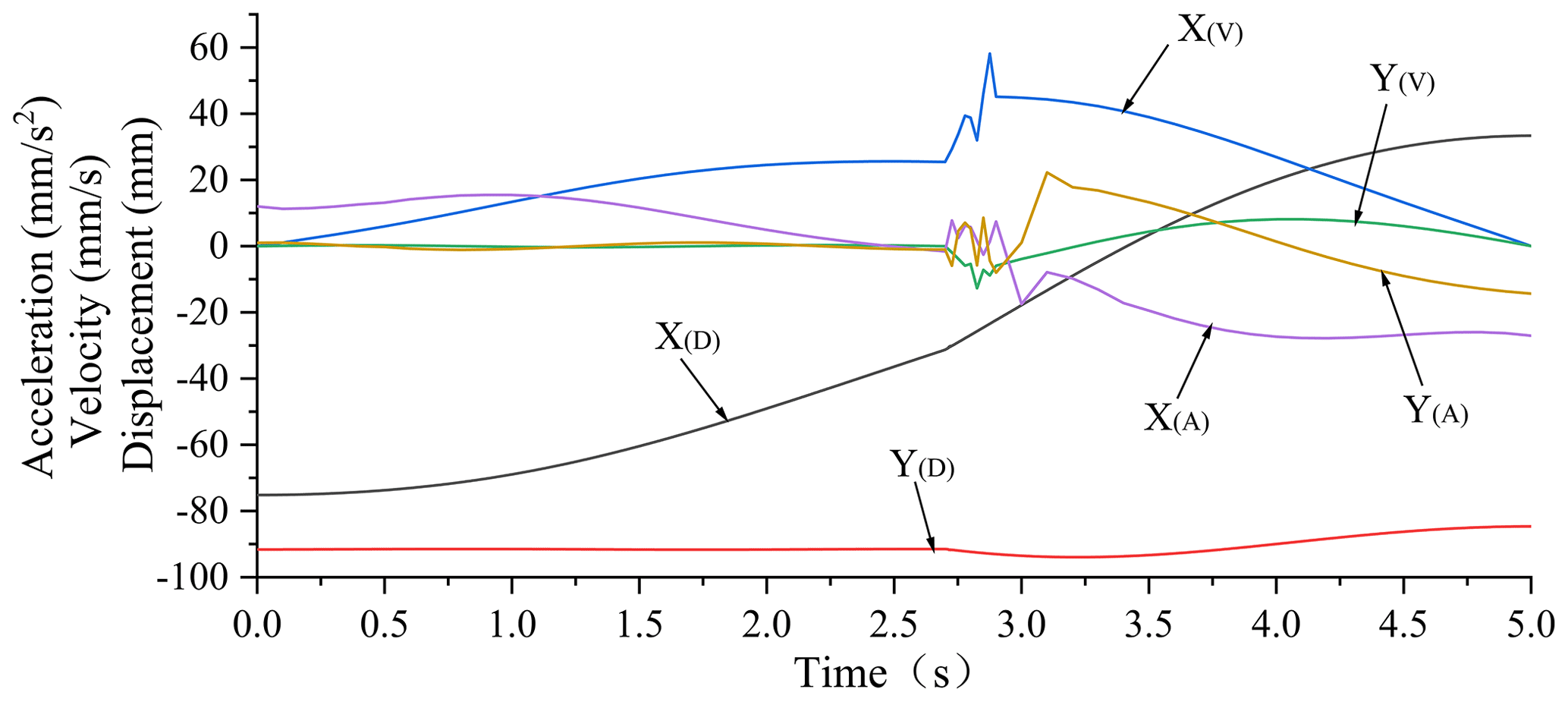
It can be seen from Fig. 8 Y(D) that the displacement of the roller in the y-axis direction remains unchanged in the straight-line flat-clamping stage, which can complete the aggregation of the leather to the center in the tiled state. After the reconstruction of the connecting link mechanism, the displacement of the roller in the y-axis direction tends to increase, which can ensure that the leather is kept in the uplift state before the clamping force is applied. According to the curve X(D), it can be seen that the displacement along the x axis has a larger trend, which indicates that the end effector has a large tension angle and meets the design requirements. After analyzing the curves X(V) and Y(V), it can be seen that the speed of the roller in the straight-line flat-clamping stage is basically constant, and the change trend is small, which meets the requirements for a uniform, stable and reliable speed when the leather converges to the center. In the whole process, except for the transient fluctuation of speed and acceleration caused by the external force of the stop block and the spring in the reconstruction stage of the linkage mechanism, the speed of the rest of the process changes smoothly, and the operation of the mechanism has no major impact, which can complete the fabric-grabbing operation stably and reliably.
5.1 The analysis and experiment of grabbing mode of the end effector
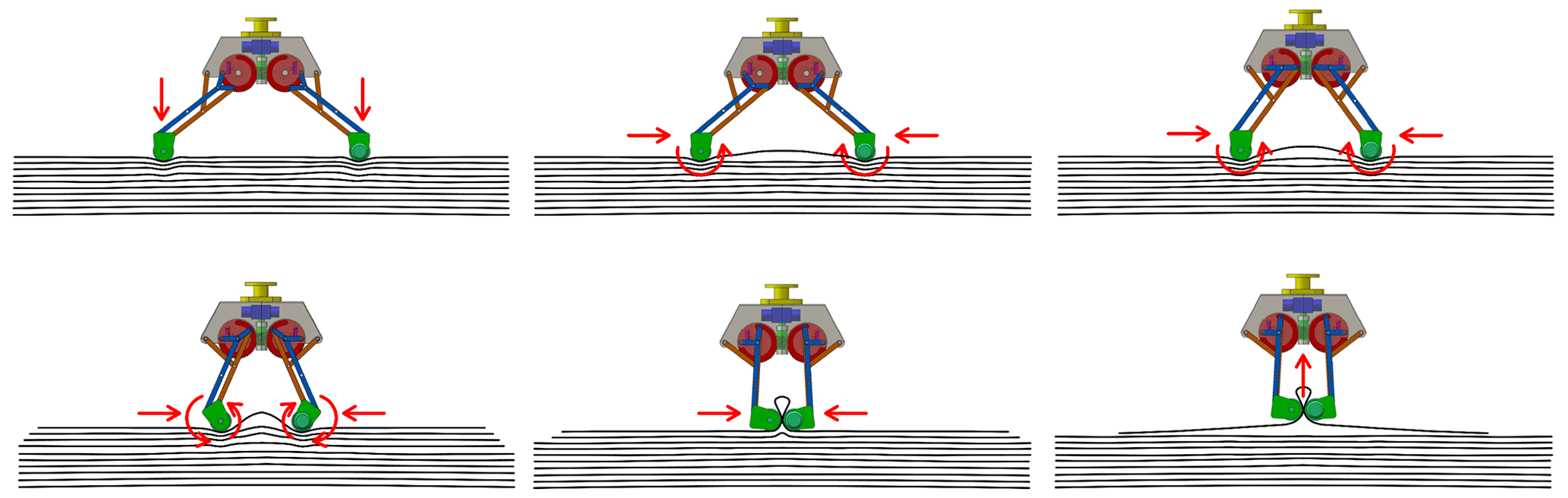
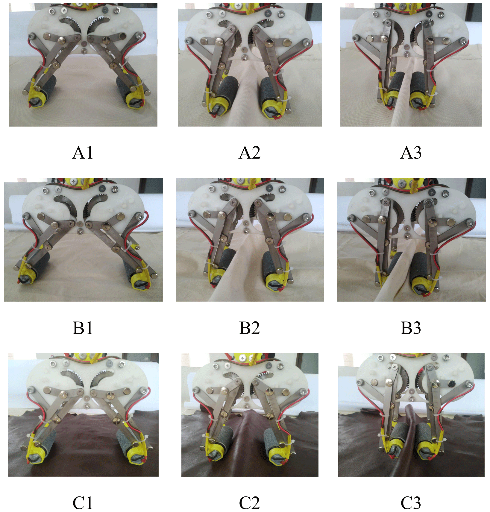
As shown in Fig. 9, the grabbing of fabric in the state of multi-layer tiling is as follows: first, open the end effector, press it down on the surface of the fabric, and make the rollers converge toward the center while making them rotate relatively. The first layer of fabric is arched by the friction force so as to clamp the arched part and realize successful grabbing.
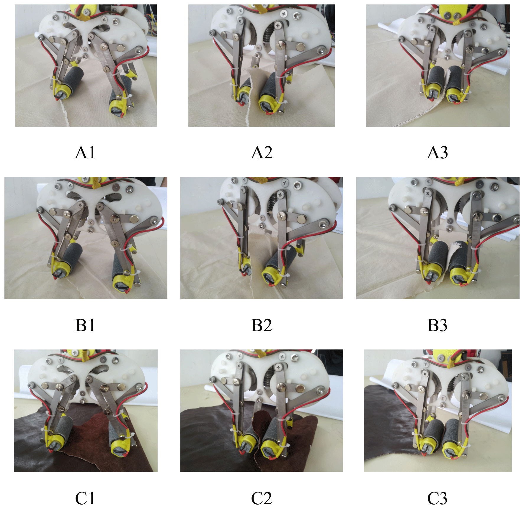
As shown in Fig. 10, tilt the end effector slightly so that the roller near the edge presses the edge of the fabric and the roller on the other side keeps a certain distance from the fabric, so that the roller can rotate to transfer the fabric between the two rollers, thereby clamping the edge of the fabric and stretching the fabric and smoothing the wrinkled area.

As shown in Fig. 11, the grabbing and spreading of the corner of fabric is as follows: when the corner of the fabric is folded, the roller presses the edge of fabric, and the roller rotates relatively to transport the fabric between two rollers, and then the fabric is folded and spread.
5.2 The making and grabbing experiment of the end effector
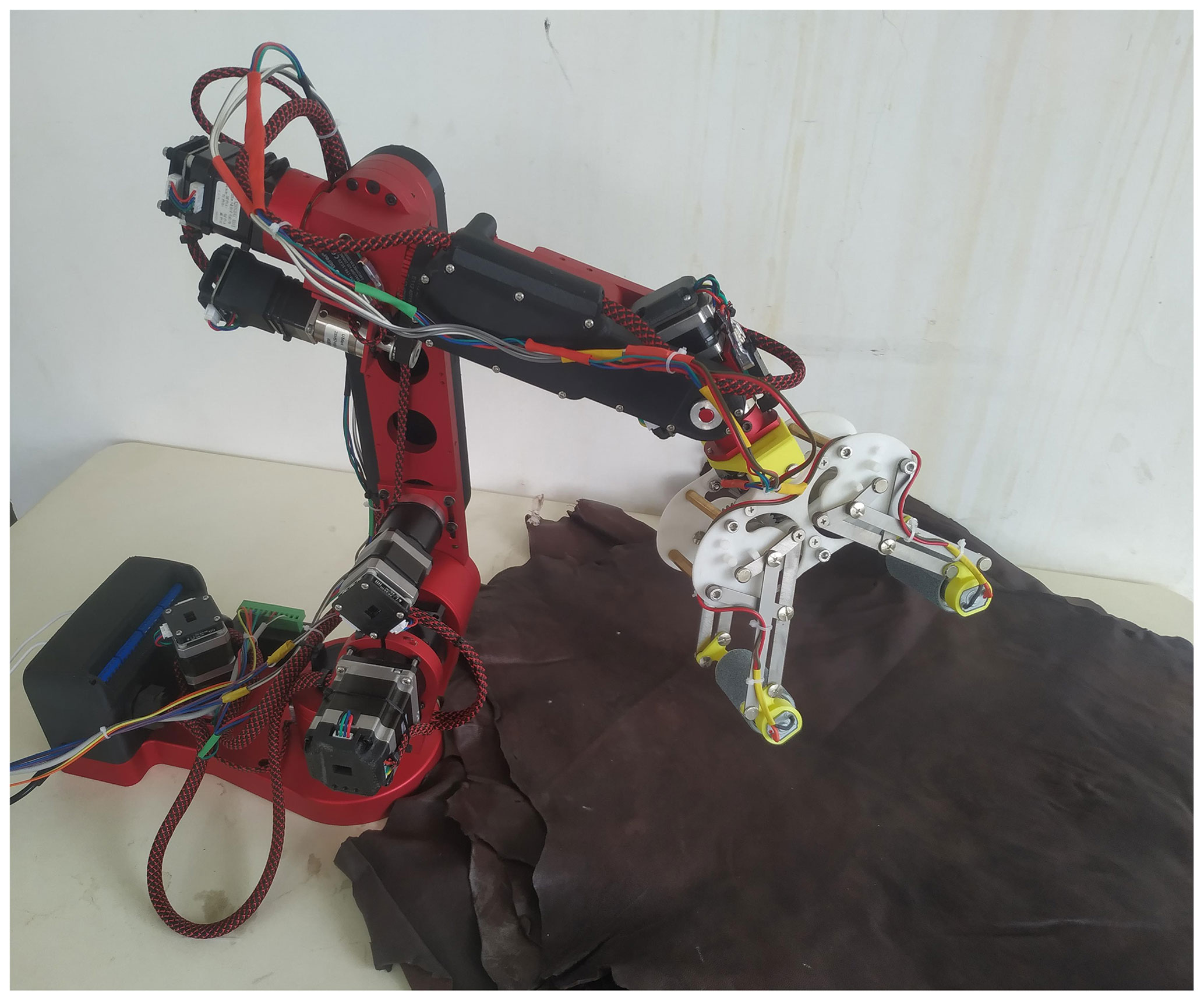
The manufacturing of end effector is as follows: based on the design of the end effector, a prototype is developed and an experimental platform is built to verify the rationality of the end-effector design. The experimental prototype is shown in Fig. 12. The roller diameter of the prototype end effector is 30 mm, the driving link length is 20 mm, and the maximum opening size is 250 mm × 150 mm × 100 mm.
Material of the roller surface is explained as follows: in order to improve the possibility of successful grabbing of the end effector, materials that can increase the rubbing force are attached to the roller surface. To grab different fabrics, two kinds of materials shown in Fig. 13 – diamond pattern on rubber surface and frosted PVC surface – can be selected. For fabrics with a smooth surface and not easy to generate scratches, the roller surface is made of PVC material, and for textiles and other fabrics that require no scratches on the surface, the rubber material is used.
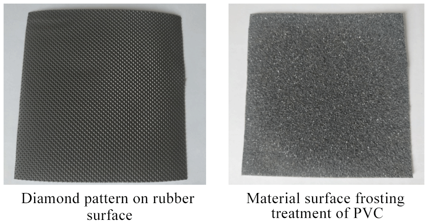
Figure 13Surface material of end-effector roller. (a) Diamond pattern on the rubber surface. (b) Material surface frosting treatment of PVC.
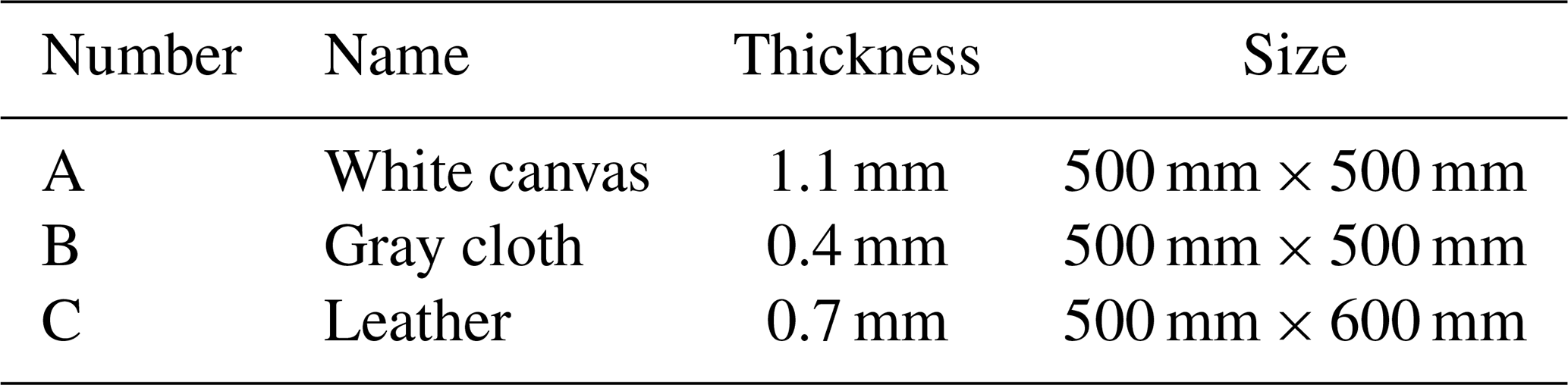
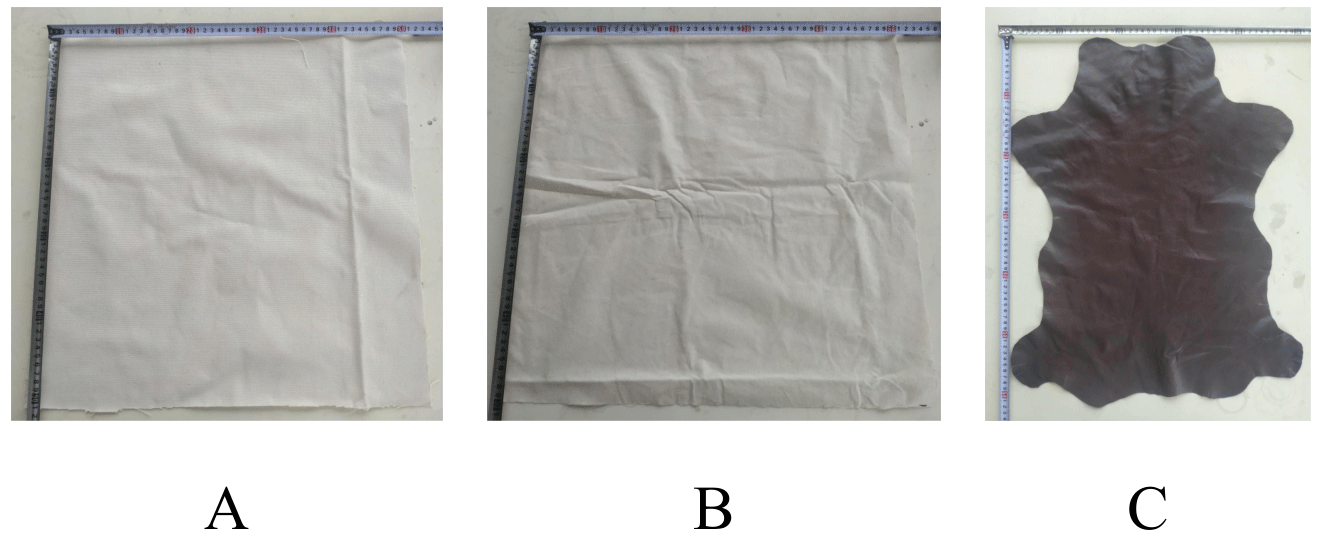
For the grabbing fabric in the experiment, select two kinds of common fabrics andbleather in a certain process, and cut the fabrics and leather into the shapes shown in Fig. 14 according to the actual production conditions. The selected fabric and leather size parameters are described below.
The selected fabric and leather size parameters are described as Table 1.
The end effector is installed on a single mechanical arm at present, and the grabbing-and-spreading process of the end effector is tested. It is considered that the middle part of the fabric can be arched and clamped, then the operation is considered to be successful.
The experimental process. According to the theoretical analysis of the grabbing process, three kinds of fabrics are respectively grabbed in the state of multi-layer tiling (Group I), stretched and spread at fabric corners (Group II) and folded corners (Group III).
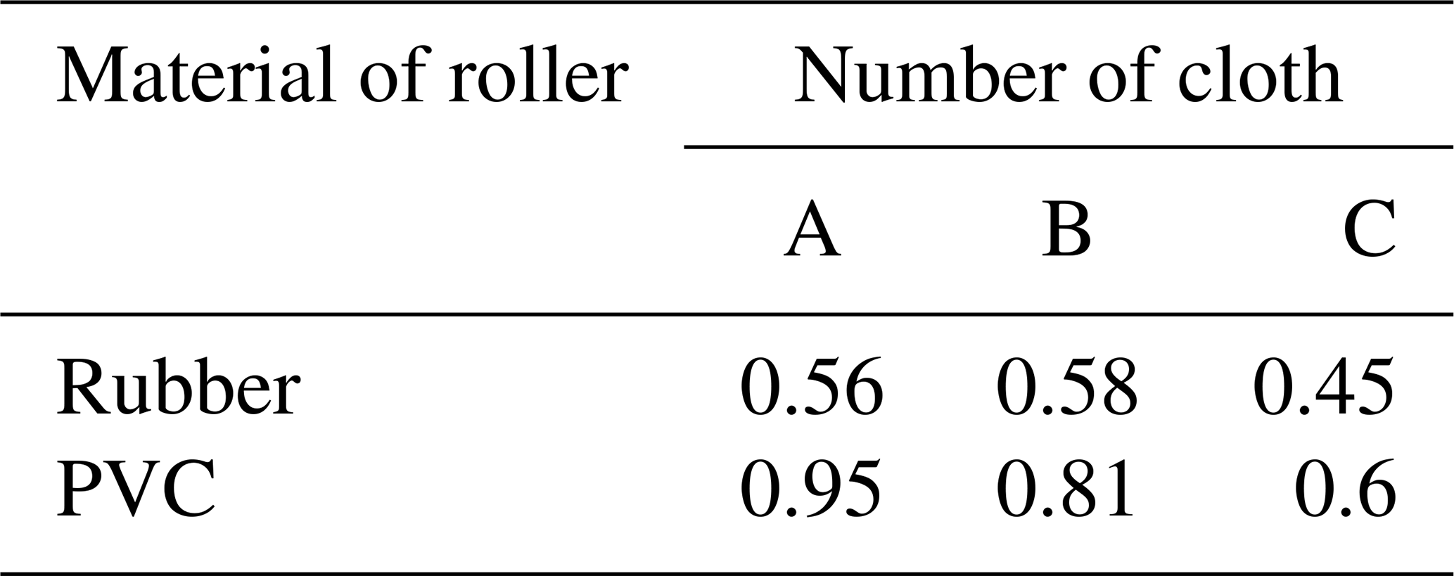
The experimental conditions. The rotating speed of the roller is set as 0.5 rad s−1 and the moving speed is 2.5 cm s−1. The initial opening distance of the end effector is 15 cm. Each group of experiments is conducted 10 times, and the number of successful experiments is recorded. The success rate is defined as the ratio of the number of successful captures to the total number of experiments. Under 2N pressure, the dynamic friction coefficients between two kinds of roller surface materials and three kinds of grabbing objects were measured, and the measured results are shown in Table 2.
The experimental process is shown in Figs. 15–17, and the experimental results are shown in Table 3.

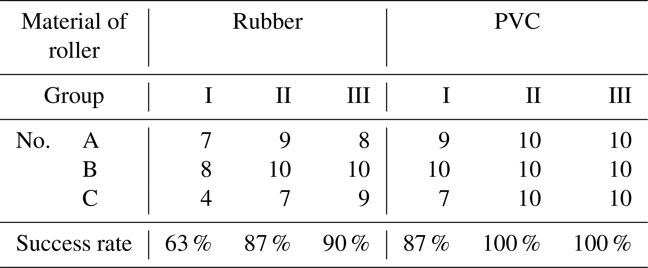
According to the analysis of the experimental results, it is found that the friction coefficient between the roller surface and the grabbing object will significantly affect the grabbing success rate. The grabbing success rate of PVC material with a high friction coefficient of roller is much higher than that of rubber material with a low friction coefficient. The same material of the roller and the grabbed fabric will also produce different experimental results. After analysis, it is due to the fact that the downward pressure of the manipulator on the grabbed fabric is not strictly controlled during the experiment. Because the flaky deformable object manipulation belongs to viscoelastic material, the friction coefficient will change with the difference of the pressing force. The success rate of grabbing the middle part of the flaky deformable object manipulation is quite different from that of grabbing the corner or corners. Through analysis, it is found that different grabbing areas will also lead to different operation results.
Comprehensive comparative analysis shows that the success of end-effector operation is influenced by many factors. The pressure in the grabbing process, the friction coefficient between the roller material and the grabbing fabric, the softness of the grabbing fabric, the grabbing position and the number of stacked layers are preliminarily considered. As there are many influencing factors, the team will explore these further in the follow-up research. The above experiments show that the designed end effector can achieve its function under the condition of selecting appropriate roller surface materials and reasonably controlling the grabbing downforce.
This paper clarifies the design requirements of the end effector for grabbing and spreading of flaky deformable object manipulation through a detailed analysis of the action of manual grabbing and spreading of leather under actual working conditions. A reconfigurable multi-link mechanism is proposed, and based on the multi-link mechanism and the roller fingertip structure, an end effector for manipulating geometric soft fabrics is designed. The working principle of the reconfigurable multi-link mechanism, the structure and grabbing mode of the end effector are introduced in detail, and the kinematics analysis and simulation of the end effector are performed. Through the development of the experimental prototype of the end effector, the grabbing-and-spreading experiments of three kinds of geometric soft fabrics under different conditions are conducted. The experimental results show that the end effector can basically meet the functional requirements, which verifies the feasibility of the end effector and the rationality of its design. However, successful grabbing and spreading can be affected by many factors, which need to be further explored.
At present, our team is conducting in-depth experiments to explore the factors that affect the success rate of operation, so as to improve the performance of the end effector. Moreover, the team will study the spreading and folding of flaky deformable object manipulation by the end effector with the help of humanoid double manipulators. Effective solutions are provided for the intelligent operation problems of geometric soft fabrics, and the development of intelligent leather manufacturing and clothing industry is actively promoted.
The data that support the findings of this study are available from the corresponding author upon reasonable request.
YH conceptualized the project, developed the methodology, prepared the original draft, and carried out the experiments. GR supervised the project and was responsible for the project administration. XS curated the data, reviewed and edited the paper. WT assisted in the experiment. All the authors have read and agreed to the published version of the paper.
The contact author has declared that none of the authors has any competing interests.
Publisher's note: Copernicus Publications remains neutral with regard to jurisdictional claims in published maps and institutional affiliations.
This research has been supported by Xi'an Science and Technology Plan Project (grant no. 2022JH-RGZN-0098) and Shaanxi Provincial Key R&D Program Funding Project (grant no. 2022GY-250).
This paper was edited by Daniel Condurache and reviewed by two anonymous referees.
Betemps, M., Redarce, H. T., and Jutard, A.: Development of a multi-spiral gripper for leather industry, in: Fifth International Conference on Advanced Robotics 'Robots in Unstructured Environments, Pisa, Italy, 19–22 June 1991, IEEE, 1722, 1726–1729, https://doi.org/10.1109/ICAR.1991.240355, 1991.
Corinaldi, D., Callegari, M., Palpacelli, M.-C., and Palmieri, G.: A Gripper for Handling Large Leather Plies Stacked on Beams, in: Proceedings of the ASME 2015 International Design Engineering Technical Conferences and Computers and Information in Engineering Conference. Volume 9: 2015 ASME/IEEE International Conference on Mechatronic and Embedded Systems and Applications, Boston, Massachusetts, USA, 2–5 August 2015, ASME, V009T07A075, https://doi.org/10.1115/DETC2015-47371, 2015.
Donaire, S., Borràs, J., Alenyà, G., and Torras, C.: A Versatile Gripper for Cloth Manipulation, IEEE Robotics and Automation Letters, 5, 6520–6527, https://doi.org/10.1109/LRA.2020.3015172, 2020.
Doulgeri, Z. and Fahantidis, N.: Picking up flexible pieces out of a bundle, IEEE Robot. Autom. Mag., 9, 9–19, https://doi.org/10.1109/MRA.2002.1019486, 2002.
Failli, F. and Dini, G.: An Innovative Approach to the Automated Stacking and Grasping of Leather Plies, CIRP Annals, 53, 31–34, https://doi.org/10.1016/S0007-8506(07)60638-6, 2004.
Glick, P., Suresh, S. A., Ruffatto, D., Cutkosky, M., Tolley, M. T., and Parness, A.: A Soft Robotic Gripper With Gecko-Inspired Adhesive, IEEE Robotics and Automation Letters, 3, 903–910, https://doi.org/10.1109/LRA.2018.2792688, 2018.
Hanafusa, H. and Asada, H.: A Robot Hand with Elastic Fingers and Its Application to Assembly Process, IFAC Proceedings Volumes, 10, 127–138, https://doi.org/10.1016/S1474-6670(17)66592-3, 1977.
Jacobsen, S. C., Wood, J. E., Knutti, D. F., and Biggers, K. B.: The UTAH/M.I.T. Dextrous Hand: Work in Progress, Int. J. Rob. Res., 3, 21–50, https://doi.org/10.1177/027836498400300402, 1984.
Jiménez, P.: Visual grasp point localization, classification and state recognition in robotic manipulation of cloth: An overview, Robot. Auton. Syst., 92, 107–125, https://doi.org/10.1016/j.robot.2017.03.009, 2017.
Koustoumpardis, P. N., Nastos, K. X., and Aspragathos, N. A.: Underactuated 3-finger robotic gripper for grasping fabrics, in: 23rd International Conference on Robotics in Alpe-Adria-Danube Region (RAAD), 3–5 September 2014, IEEE, 1–8, https://doi.org/10.1109/RAAD.2014.7002271, 2014.
Koustoumpardis, P. N., Smyrnis, S., and Aspragathos, N. A.: A 3-Finger Robotic Gripper for Grasping Fabrics Based on Cams-Followers Mechanism, in: Advances in Service and Industrial Robotics, edited by: Ferraresi, C. and Quaglia, G., Springer, Cham, 612–620, https://doi.org/10.1007/978-3-319-61276-8_64, 2018.
Lee, J.-H., Chung, Y. S., and Rodrigue, H.: Long Shape Memory Alloy Tendon-based Soft Robotic Actuators and Implementation as a Soft Gripper, Scientific Reports, 9, 11251, https://doi.org/10.1038/s41598-019-47794-1, 2019.
Mantriota, G.: Optimal grasp of vacuum grippers with multiple suction cups, Mech. Mach. Theory, 42, 18–33, https://doi.org/10.1016/j.mechmachtheory.2006.02.007, 2007.
Okada, T. and Kanade, T.: Appropriate lengths between phalanges of multijointed fingers for stable grasping, J. Robotic Syst., 1, 223–234, https://doi.org/10.1002/rob.4620010302, 1984.
Ono, E. and Kunikatsu, T.: On better pushing for picking a piece of fabric from layers, in: 2007 IEEE International Conference on Robotics and Biomimetics (ROBIO), Sanya, China, 15–18 December 2007, IEEE, 589–594, https://doi.org/10.1109/ROBIO.2007.4522228, 2007.
Sun, B. and Zhang, X.: A New Electrostatic Gripper for Flexible Handling of Fabrics in Automated Garment Manufacturing, in: 2019 IEEE 15th International Conference on Automation Science and Engineering (CASE), Vancouver, BC, Canada, 22–26 August 2019, IEEE, 879–884, https://doi.org/10.1109/COASE.2019.8843149, 2019.
Von Drigalski, F., Yoshioka, D., Yamazaki, W., Cho, S.-G., Gall, M., Eljuri, P. M. U., Hoerig, V., Ding, M., Takamatsu, J., Ogasawara, T., and Beltran, J.: NAIST Openhand M2S: A Versatile Two-Finger Gripper Adapted for Pulling and Tucking Textile, in: 2017 First IEEE International Conference on Robotic Computing (IRC), Taichung, Taiwan, 10–12 April 2017, IEEE, 117–122, https://doi.org/10.1109/IRC.2017.55, 2017.
Yamazaki, K. and Abe, T.: A Versatile End-Effector for Pick-and-Release of Fabric Parts, IEEE Robotics and Automation Letters, 6, 1431–1438, https://doi.org/10.1109/LRA.2021.3057053, 2021.
- Abstract
- Introduction
- The design requirements and analysis of end effector
- The design of end effector
- The kinematics analysis and simulation of the end effector
- The analysis and experiment of grabbing mode of the end effector
- Conclusion
- Data availability
- Author contributions
- Competing interests
- Disclaimer
- Financial support
- Review statement
- References