the Creative Commons Attribution 4.0 License.
the Creative Commons Attribution 4.0 License.
 | 13 Oct 2022
Analysis of the coaxiality–geometric hysteresis model of a rotate vector reducer based on Ansys Adams
Yongming Liu
Lei Fu
Zhuanzhe Zhao
Qiang Ma
Yujian Rui
Zhen Zhang
When a traditional performance test device, the rotate vector (RV) reducer, is loading and unloading the reducer tested or running in different torque ranges, the coaxiality error generated by the transmission system has an important impact on the detection accuracy of a key performance parameter of the RV reducer, the hysteresis. In order to design a high-precision performance test device, a RV reducer coaxiality–geometric hysteresis model is proposed. First of all, the static simulation analysis of the transmission system of the traditional performance test device in different torque ranges is carried out using Ansys software, and the corresponding coaxiality error is obtained. Secondly, the RV reducer coaxiality–geometric hysteresis model is established by means of geometric analysis, and combined with Adams dynamics simulation software, the dynamic simulation analysis is carried out under the condition that the coaxiality of the model transmission system is in different error ranges and has no load. When the coaxiality is within the allowable error range, the hysteresis value is 0.5467 arcmin, and the result shows that the accuracy of the model is verified. At the same time, when the coaxiality exceeds the allowable range of error, it will have a great impact on the hysteresis. This result has certain theoretical significance and practical value for the analysis of the influence of the coaxiality error of the high-precision RV reducer performance detection device and the design of the adjustment mechanism.
- Article
(1316 KB) - Full-text XML
- BibTeX
- EndNote


The rotate vector reducer has a series of advantages such as small size, light weight, large transmission ratio range, long life, high precision, high efficiency, and stable transmission and has been widely used in industrial robots, CNC (computer numerical control) machine tools, and other fields (Yu et al., 2017; Qian et al., 2020; Wang et al., 2019). Hysteresis is one of the most important technical parameters and indicators in the application of RV reducers (Pham and Ahn, 2017; T. Li et al., 2020). Due to confidentiality and other reasons, it is difficult to obtain technical data, which brings certain difficulty to the theoretical calculation. At the same time, the hysteresis parameters calculated by theory are often limited by various factors and can only be used as reference values. Therefore, scholars at home and abroad put forward many methods and factors to calculate and influence hysteresis, and some achievements are as follows: Tran et al. (2016) combined finite element and kinematics analysis to study the idling of the cycloidal pin gear reducer, first considering the effect of tolerance on the idling of the cycloidal pin gear reducer and then conducting an iterative finite element analysis of the idling of the cycloidal pin gear reducer. The results show that the lost motion of the cycloid reducer depends not only on its torsional stiffness but also its tolerance. T. Tang et al. (2021) proposed a new model to capture transmission compliance and hysteresis and its degradation. This phenomenon is represented by the combination of nonlinear stiffness components and micro-sliding friction in the tooth meshing area. The proposed model takes into account the interference effects of multi-tooth meshing and the reducer. The parameters of the model are determined using optimization techniques, and special harmonics are used. Numerical simulation and driving test equipment experimental data are compared to prove the proposed model. Bednarczyk (2021) uses an output mechanism to transmit the driving force from the active side of the main rolling node gear of the cycloid reducer to the output side. And through the structure and geometry of the output mechanism, the backlash distribution in it is analyzed, while considering the formation of the machining deviations of the elements and surfaces of the mechanism, determining the distribution of forces and contact pressures. The analysis results show that the backlash distribution, force, and contact pressure are highly dependent on the bushing arrangement radius and the tolerance of the planetary gear bore. According to the elastic deformation theory of the thin shell, the principle of harmonic transmission and the source of the harmonic transmission error are analyzed, and the calculation of the transmission error is further discussed; the transmission error formula of the harmonic gear reducer considering the gear backlash and stiffness is given in Tong et al. (2013). The detection system of the transmission error of the gear reducer is designed for the first harmonic. The system realizes the detection of static and dynamic transmission errors of the harmonic gear reducer. Zou et al. (2015) propose a new harmonic drive model, which takes into account the geometry, internal interactions, and assembly errors of key parts; uses low-speed tests to fit kinematic errors; and analyzes its generation mechanism. Based on the new model, a speed step simulation, the new model reveals the dynamic behavior of harmonic drive systems, which will aid in the dynamic design and precise control of harmonic drive systems. T. Li et al. (2020) took the RV cycloid pin gear transmission as the research object, considered the influence of manufacturing errors, established the theoretical contact analysis model of the cycloid pin gear transmission, realized the effective pre-control of the tooth profile and meshing contact performance through the analysis, and verified the analysis results. These showed that the manufacturing error has a great influence on the transmission accuracy of the RV cycloid pin gear, and the pitch error has the greatest influence on the transmission error, which is directly proportional. The tooth profile error has a secondary effect on the transmission error. Ahn et al. (2021) considered the tolerance and friction between the cycloid and the needle, established the finite element model of the RV reducer and the eccentric shaft, and verified it through theoretical calculations. At the same time, they studied the tolerance and friction of the multi-contact RV, and the effect of the output torque of the reducer shows that the tolerance is mainly to reduce the torsional stiffness, while the friction mainly increases the fluctuation of the output torque. Based on the functional principle and the influence of wear, a performance margin model was established with hysteresis and transmission errors as the key performance parameters, and then the multi-source uncertainty was analyzed and quantified, including manufacturing errors, uncertainties in operating, and environmental conditions in Z. Li et al. (2020). And then the multi-source uncertainty was analyzed and quantified, including manufacturing errors, uncertainties in operation, uncertainty of the threshold, and environmental conditions in Y. Li et al. (2020). The research results show that the proposed method can provide some suggestions for the design and manufacturing stage of the harmonic reducer.
The hysteresis generated during the rotary motion of the RV reducer and the test system is affected by various factors, and the position of the instantaneous rotary axis changes frequently. According to the principle of relative motion, at any instant, on the one hand the axis of rotation rotates around its own instantaneous axis of rotation. On the other hand, the instantaneous axis of rotation also moves axially, radially, and obliquely with respect to the ideal axis of rotation. The coaxiality error of the RV reducer and the test system is the maximum radial distance between the rotation axis and the reference axis, which will cause the rotation axis of the rotating shaft to deviate from the correct position, affecting the centering accuracy and orientation accuracy of the RV reducer and the testing system shafting, so that the hysteresis of the RV reducer and the test accuracy of the detection device have changed.
The research content in the above literature does not involve the influence of the geometric error of the coaxiality on the hysteresis of the RV reducer and its test accuracy. At the same time, the established model is too complicated, and the generalization ability is limited, which brings inconvenience to the actual RV reducer geometric hysteresis design, detection accuracy, and engineering application.
This paper takes the RV-20E reducer as a subject, establishes the coaxiality–geometric hysteresis model of the RV reducer, and conducts in-depth research on the influence of coaxiality error on RV reducer hysteresis and its test accuracy. Firstly, the coaxiality error of the transmission system of the traditional performance test device under different loads is analyzed by Ansys software; secondly, the coaxiality–geometric hysteresis model of the RV reducer is established by the method of geometric analysis, and the dynamic simulation analysis is carried out with Adams. The accuracy of the model is verified; at the same time, dynamic simulation analysis is carried out when the coaxiality of the model is within different error ranges and the output end has no load, and the influence of different coaxiality on the hysteresis is given. The coaxiality of the high-precision detection device for the performance of the reducer, the hysteresis of the RV reducer, and the design of its adjustment mechanism have certain theoretical significance and practical value.
According to the RV reducer–transmission relationship, the geometric hysteresis of the RV reducer mainly consists of the following three parts: the geometric hysteresis of the gradient cylinder gear drive (primary deceleration), the geometric hysteresis of needle wheel planetary transmission (secondary deceleration), and the geometric hysteresis of the eccentric-rotation arm bearing. Since each tooth surface of the reducer is rigidly engaged, the geometric hysteresis of the coaxiality of the RV-20E reducer is analyzed as follows.
2.1 Statics model based on the establishment of Ansys
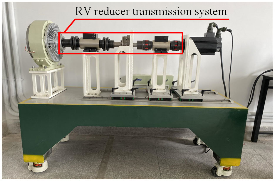
The performance test device, the RV reducer, is a mechanical device used to detect key parameters such as the hysteresis value. As shown in Fig. 1, during the test process, the coaxiality error of the transmission system of the device will affect the RV reducer deceleration. In order to further explore the influence of the coaxiality error on the hysteresis of the RV reducer during operation, Ansys software was used to perform statics simulation analysis on the transmission system of the traditional RV reducer performance testing device, so as to obtain the possible coaxiality errors of the input shaft and output shaft of the RV reducer during the operation of the transmission system (Yang et al., 2019; Gao et al., 2012; Su et al., 2020); the model building steps are as follows.
2.1.1 Simplified transmission system model
First of all, the RV reducer performance testing device was established with a 3D solid model through SolidWorks, and then unnecessary parts were removed, such as the support, base, and slider, leaving the parts required for the transmission system. The simplified model is shown in Fig. 2.
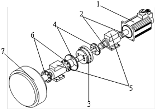
Figure 2Simplified model of transmission system: (1) servo motor, (2) plum blossom coupling, (3) RV reducer, (4) raster encoder, (5) torque sensor, (6) diaphragm coupling, and (7) magnetic powder brake.
2.1.2 Parameter setting of non-mechanical parts of the transmission system
Since non-mechanical parts belong to the instrument category, specific material properties cannot be given, so materials are added according to the principle of equal mass conversion. The specific parameters are shown in Table 1.
Table 1Material parameters of non-mechanical parts of the transmission system.

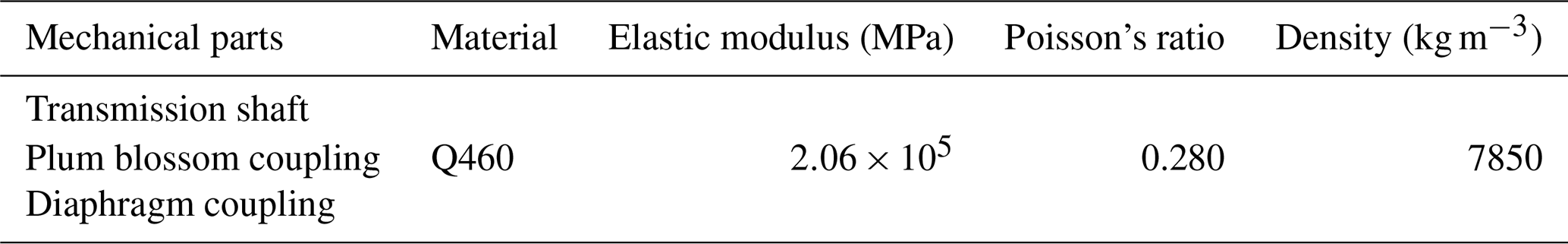
2.1.3 Material parameter setting of mechanical parts of the transmission system
The material properties of the mechanical parts of the transmission system are added, and the specific parameters are shown in Table 2.
Table 2Material parameter table of the mechanical parts of the transmission system.
2.1.4 Setting of boundary conditions of transmission system
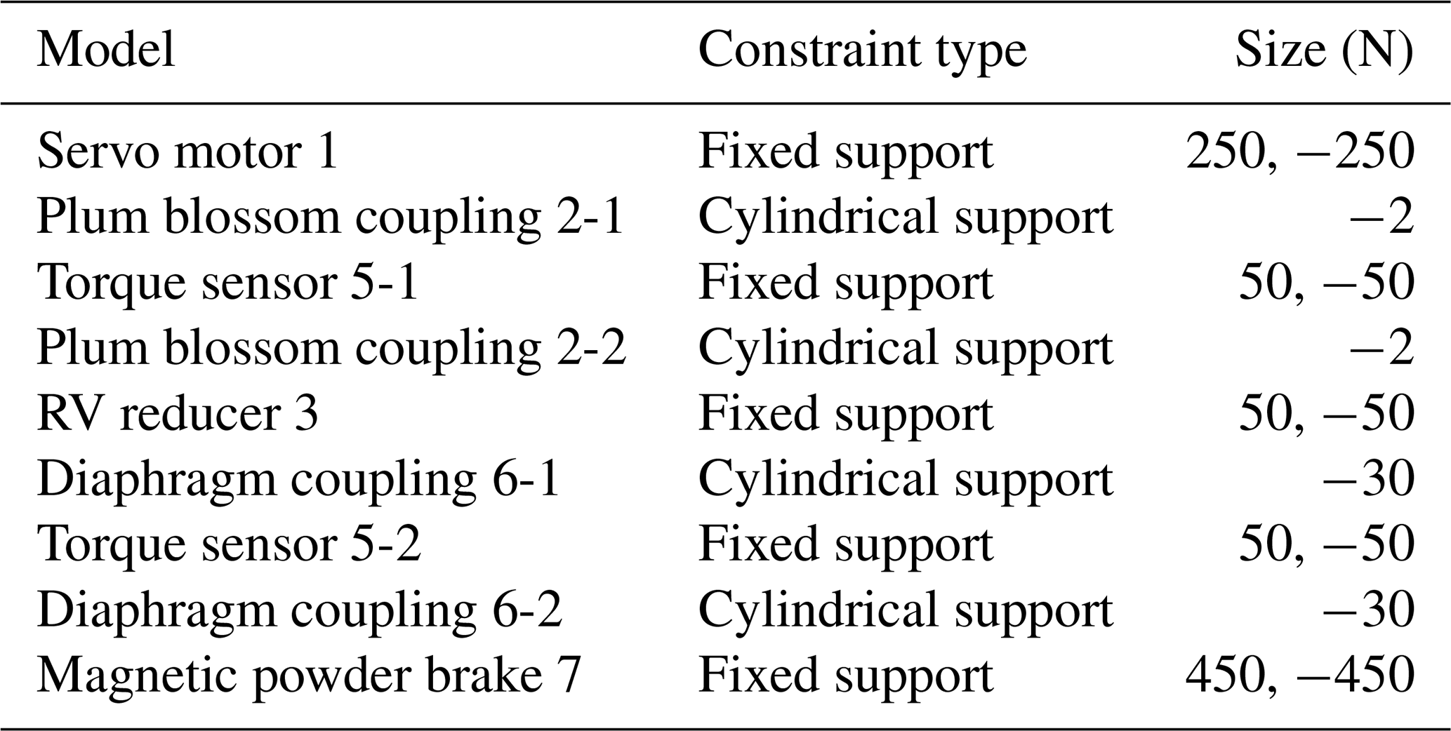
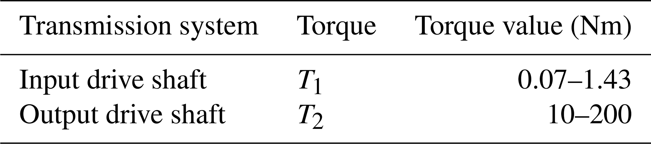
Figure 3 shows the setting of the boundary conditions of the simplified model in Ansys software. The specific parameters are shown in Tables 3 and 4. Table 3 shows the boundary gravity of mechanical and non-mechanical transmission systems when g=9.8 m s−2. The non-mechanical parts are fixed on the base, so they are subjected to reaction force. The boundary torque in Table 4 is the range of the torque sensor selected during actual measurement.
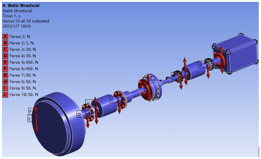
Table 3The force parameter table of the transmission system model.
2.2 Ansys simulation results
Through Ansys to analyze the input shaft and output shaft of the transmission system, the cloud displacement path change in the y direction can be obtained. This article takes a set of boundary conditions in Table 4 (input shaft T1=1.43 Nm, output shaft T2=200 Nm) as an example. After analysis, the simulation effect is shown in Fig. 4, and the radial displacement change is shown in Fig. 5.


The tilt model of the input and output drive shafts from Fig. 4 is established as shown in Fig. 6.
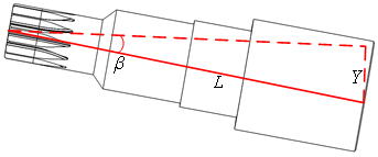
The angle calculation Eq. (1) can be listed from the model in Fig. 6, and the maximum cloud displacement in the y direction is obtained through the path change curve of the axis in Fig. 5, and the actual inclination angle of the axis is calculated.
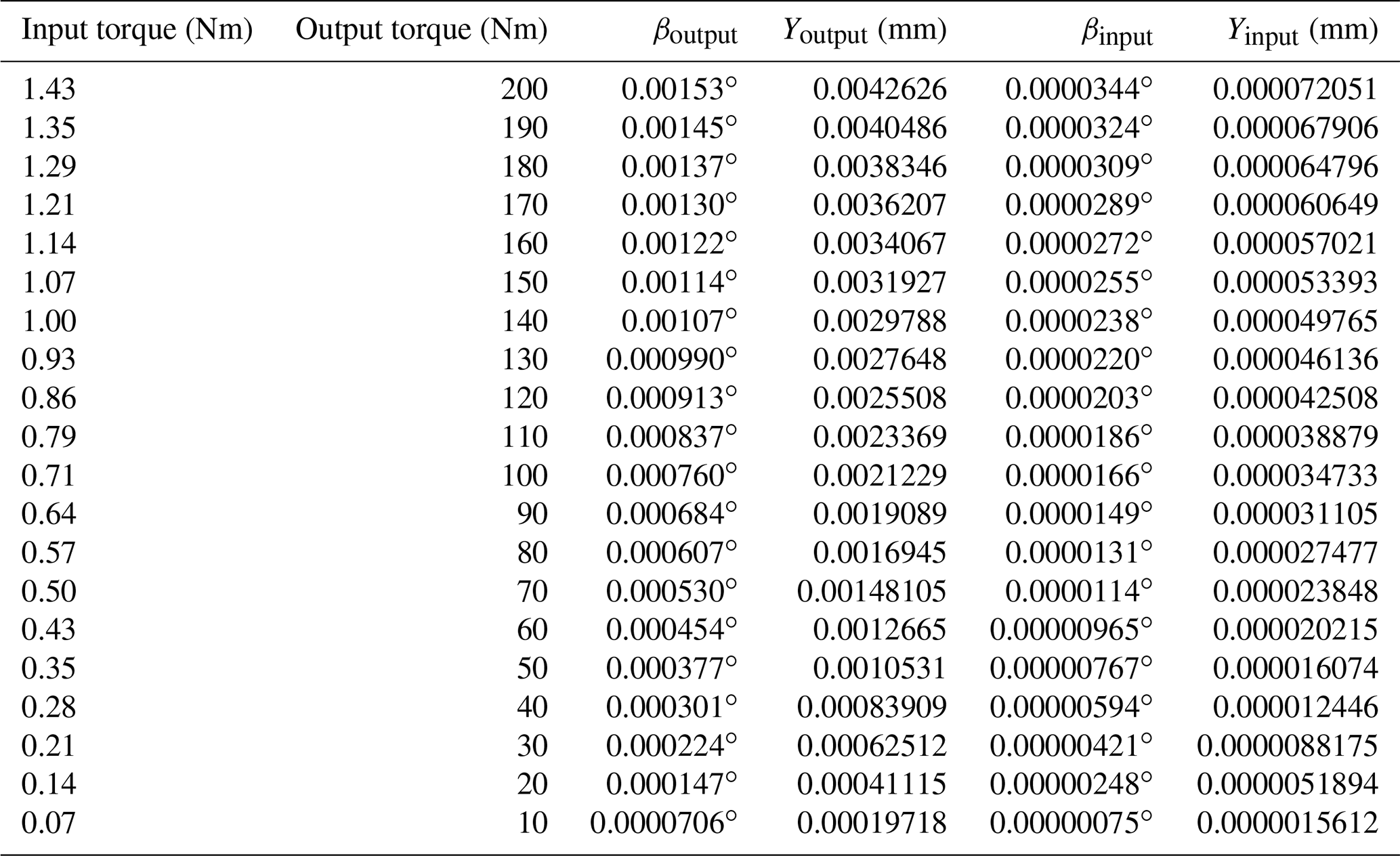
The calculation results are shown in Table 5. Table 5 shows the inclination angles of the input shaft and output shaft under different torque conditions when the RV reducer is actually running.
(Note that β represents the radial tilt angle of the shaft; L indicates the shaft length of the input and output ends of the RV reducer, where Loutput=160 mm, and Linput=120 mm; and Y indicates the maximum cloud displacement value in the y direction.)
3.1 Transmission ratio of RV-20E reducer
The mechanical structure of the RV reducer is shown in Fig. 7, and its transmission principle is as follows.
Sun gear no. 1, as the main input mechanism, transmits the motion to the involute planetary gear no. 2 to complete the first stage of deceleration. The planetary gear no. 2 is connected with the crank shaft no. 3 and transmits the motion of the planetary gear no. 2 to the crank shaft no. 3, and the crank on the crank shaft no. 3 drives the cycloidal gear no. 4, so that the cycloidal gear no. 4 produces eccentric motion. At the same time, the cycloidal gear no. 4 meshes with the pin gear no. 5 to make the cycloid gear no. 4 produce autorotation motion, and the autorotation motion of the cycloid gear no. 4 will be transmitted to the planet carrier (output disc no. 6) through the crank shaft no. 3 to realize constant speed output rotation, completing the second stage of deceleration.
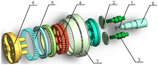
Figure 7RV-20E reducer structure diagram: (1) sun gear, (2) planet gear, (3) crank shaft, (4) cycloid gear, (5) pin gear, (6) output disk, (7) needle tooth shell, and (8) the input shaft.
According to Fig. 7, the transmission ratio of the RV reducer can be obtained as follows:
-
the transmission ratio of the first-stage involute planet gear,
-
the transmission ratio of the second-stage cycloid pin gear planetary transmission,
-
the transmission ratio of the RV-20E reducer structure,
In the formulas, n1 and n2 are the rotational speeds of the sun gear and planet gears, n6 is the rotational speed of the output shaft (the output tray), Z1 and Z2 are the number of teeth of the sun gear and planet gears, n3 and n4 are the crank shaft and cycloid gear respectively, n5 is the speed of the pin gear (the needle tooth shell is fixed), and Z4 and Z5 are the number of teeth of the cycloidal gear and the pin gear, respectively. According to the working and structural principles of the reducer, the rotation speed of the output shaft is equal to the rotation speed of the cycloid gear; i.e., n6=n4 and n3=n2
3.2 Coaxiality–geometric difference model of involute cylindrical gear transmission
When the RV reducer is running, the central shaft (input shaft) of the input end has a coaxiality error, and the meshing of the sun gear and the planetary gear will be affected, which will further lead to the hysteresis of the first-stage involute planetary gear transmission. For this situation, this paper takes the RV-20E reducer as an example to mathematically model the coaxiality error at the input end of the reducer. The model is as follows: the gear meshing model and the force analysis model when the input end is running normally, as shown in Fig. 8a and c, and the gear meshing model and force analysis model when there is a coaxiality error at the input, as shown in Fig. 8b and d.
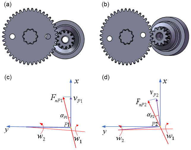
Figure 8Actual tilt model of input shaft. (a) Normal meshing of input shaft gears (left view). (b) Input shaft gear inclined meshing (left view). (c) Normal parameter model analysis diagram (left view). (d) Analysis diagram of tilt parameter model (left view).
When calculating the hysteresis of the involute planetary gear transmission (the first stage deceleration), the gear hysteresis caused by the average deviation of the length of the common normal is mainly considered. As shown in Fig. 8c, when the input shaft is not tilted, the hysteresis error Δϕ12 is generated by the transmission of the involute gear transmission part to the output end, as shown in Eq. (5).
As shown in Fig. 8d, when the input shaft is tilted, its meshing pressure angle changes, and the new involute hysteresis error is derived as follows.
Then the hysteresis error Δϕ12 generated by the involute gear transmission part transmitted to the output end can be converted into , as shown in Eq. (12).
where Ews and Ewi are the hysteresis caused by the average deviation of the length of the common norma, r1 is the indexing radius of the sun gear, β is the radial tilt angle of the shaft, w2 is the angular velocity of the planetary gear, a0 is the center distance when the sun gear and planetary gear are in normal meshing, a1 is the radial displacement when the sun gear and the planet gear mesh, z1 is the number of teeth on the sun gear, z2 is the number of teeth on the planetary gear, and m2 is the mass of the planetary gear.
(Note that since the RV reducer is a precision instrument and the size router diameter ≤ 500 mm, it can be known that its grade is between IT1–IT5 by searching the standard tolerance table GB/T1800.1-2009, so it can be obtained that a1 = 0.00000075–0.0000045 m.)
3.3 Cycloid pin wheel planetary gear drive coaxiality–geometric hysteresis
The formula for solving Δϕ34 generated by the planetary transmission part of the cycloid pin gear is
where Δrrp is the isometric modification amount, Δrp is the shift modification amount, e is the cycloid eccentricity, zc is the number of cycloidal gear, and K1 is the short width coefficient.
Since the secondary cycloid pin wheel planetary transmission belongs to the internal transmission of the RV reducer, the error caused by the tilt of its own shaft is not considered, and the basic error parameters are summed to obtain the hysteresis generated by the cycloid pin wheel planetary transmission part Δϕ34, as shown in Eq. (16).
Kn is the center distance to produce the coefficient of hysteresis, as shown in Eq. (17).
where Δrrp is the isometric modification amount, Δrp is the shift modification amount, δrp is the deviation of the pin gear center circle radius, δrrp is the pin gear pin radius error, δrrp is the matching clearance between the pin gear pin and the pin hole, ΔFr is the radial circle runout error of the cycloidal gear ring, δt is the circumferential position error of the pin hole of the pin gear, ΔFp is the cumulative error of the circumferential pitch of the cycloidal gear, δΔrrp is the offset modification error, δΔrp is the shift modification error, δe is the eccentricity error, K1 is the short width coefficient, e is the cycloid eccentricity, zc is the number of cycloidal gear, and rp is the radius of the pin gear.
3.4 Bearing gap coaxiality–geometric hysteresis
The swing arm bearing of the RV reducer has a certain clearance, so it will produce a corresponding hysteresis. The calculation of the hysteresis is shown in Eq. (18).
where Δu is the clearance of the arm bearing, and a0 is the center distance between the planetary gear and the sun gear.
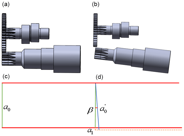
Figure 9Actual tilt model of input shaft. (a) Normal meshing of input shaft gears (top view), (b) Input shaft gear inclined meshing (top view). (c) Normal parameter model analysis diagram (top view). (d) Analysis diagram of tilt parameter model (top view).
It can be seen from Fig. 9d that when the sun gear is tilted, the center distance of its gears will inevitably change accordingly, and the hysteresis Δϕ56, generated by the transmission of the rotor arm bearing clearance to the output end, can be converted into , as shown in Eq. (20).
where a1 is the radial displacement when the sun gear and the planet gear mesh, and β is the radial tilt angle of the shaft.
Equations (12), (16), and (20) are added to calculate the overall hysteresis of the RV reducer, as shown in Eq. (21).
5.1 Establishment of kinematic model based on Adams
In order to verify the accuracy of the coaxiality–geometric hysteresis model, a simulation analysis of the RV-20E reducer under no load based on Adams was conducted (Y. Tang et al., 2021; Xu et al., 2017; Wei et al., 2015), and the model establishment steps are as follows.
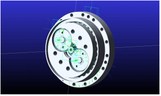
5.1.1 Establish 3D model and import it into Adams
Firstly, the three-dimensional model of the RV-20E reducer is established through SolidWorks and then imported into Adams. The interface and model are shown in Fig. 10; the vinput=14 r min−1 and then voutput=1 r min−1.
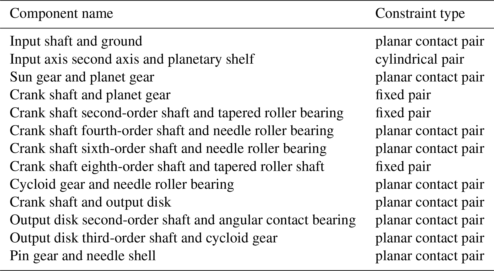
5.1.2 Establishment of Adams constraints
The constraint pairs of the RV reducer kinematic model based on Adams are shown in Table 6.
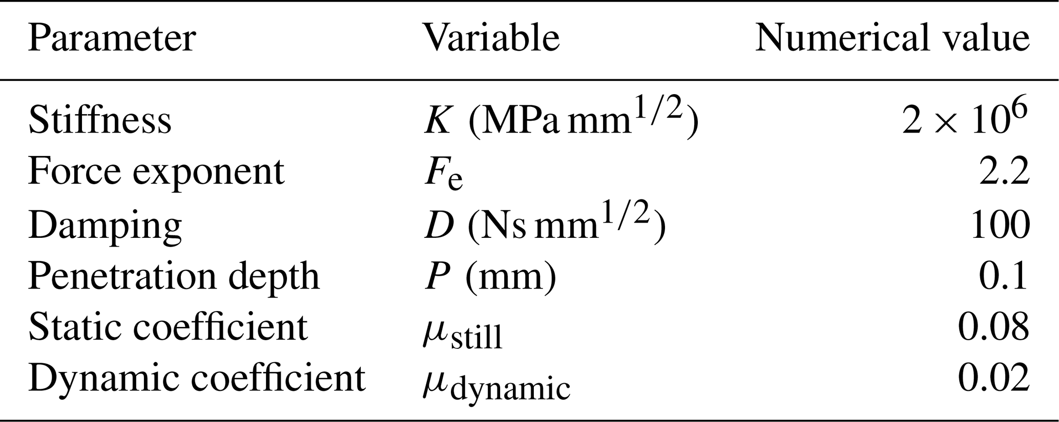
5.1.3 Setting of Adams load
The impact function method (Chatterjee and Bowling, 2019) is used to calculate the contact force in the involute spur gear transmission of the RV-20E reducer. According to the Hertzian static elastic contact theory, the following equation is obtained.
where K is the stiffness coefficient (MPa mm), R3 is the pitch circle radius of the outer gear (mm), R4 is the pitch circle radius (mm) of the internal gear, u1 is Poisson's ratio of involute center gear material, u2 is Poisson's ratio of involute planetary gear material, E1 is the elastic modulus of the sun gear material (MPa), and E2 is the elastic modulus of the planetary gear material (MPa).
The calculation results show that MP mm, and the specific parameters of contact force are shown in Table 7.
5.2 Simulation analysis of geometric hysteresis
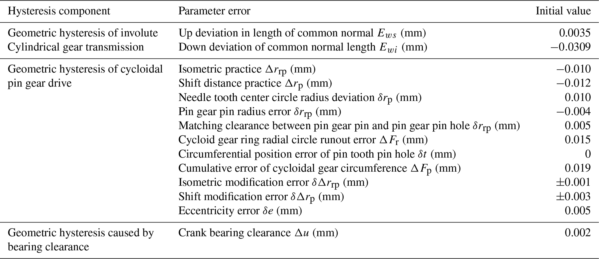
(1) The basic size parameters of RV-20E reducer are shown in Table 8. The upper limit should be taken within the processing requirement level. The initial value of the system error parameter is shown in Table 9.
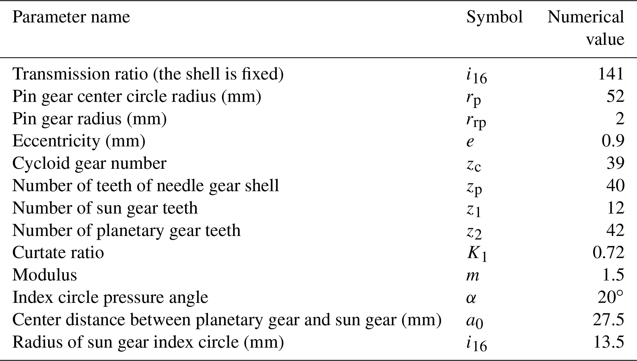
Table 9The initial values of the parameter error corresponding to the difference components.
(2) When the sun gear 1 of the RV reducer is engaged and the input shaft does not produce axial tilt, the normal force on the index circle of the planetary gear is obtained through Adams simulation, as shown in Fig. 11.

It can be seen from Fig. 11 that N. Substituting the initial values of the system parameters in Tables 8 and 9 into Eq. (21), the calculation is ΔϕΣ=0.5467 arcmin. Since it can be seen that the hysteresis of the RV reducer is generally ≤1 arcmin, the model is correct.
5.3 Concentricity–geometric hysteresis model comparative analysis
Next, in conjunction with Table 5, when the RV reducer sun gear 1 is engaged and the input shaft produces a different range of axial inclination, the normal forces on the index circle of the planetary gear are obtained through Adams simulation, as shown in Fig. 12.
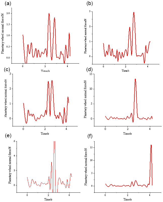
Figure 12Planetary gear normal force within the error range of different axis degrees. (a) The input shaft is inclined at 0.00000767∘. (b) The input shaft is inclined at 0.0000131∘. (c) The input shaft is inclined at 0.0000186∘. (d) The input shaft is inclined at 0.0000238∘. (e) The input shaft is inclined at 0.0000289∘. (f) The input shaft is inclined at 0.0000344∘.
Figure 12 shows the normal forces of the planetary gears in the range of different axis degrees obtained by the simulation. Substitute Eq. (21) to calculate the hysteresis, as shown in Table 10.
Table 10Hysteresis within the range of different axial degrees.
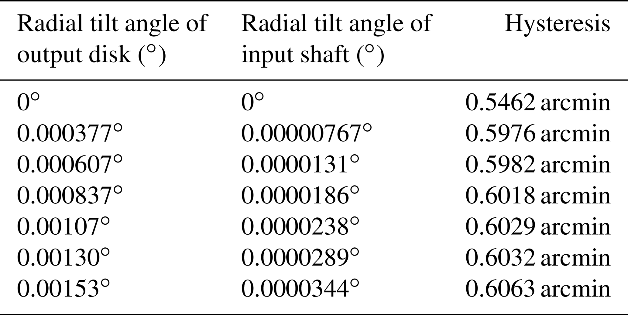
It can be seen from Table 10 that when the coaxiality of the RV reducer transmission system exceeds the allowable error range, the hysteresis error has a tendency to continuously increase, which will make the angle data measured by the grating encoder unable to accurately reflect the accuracy of the geometric hysteresis of the RV reducer. At the same time, when the coaxiality of the RV reducer transmission system exceeds the allowable error range, the increase in the hysteresis is irregular, which may be caused by friction with the shaft.
The coaxiality–geometric hysteresis model of the transmission system of the RV reducer is established, and the model is simulated and analyzed with Adams software under the condition that the coaxiality is within different error ranges and there is no load, and the results verify the accuracy of the model. At the same time, the results show that coaxiality is one of the main factors affecting the size of the hysteresis.
The measurement method of the hysteresis of the RV reducer has not been standardized, and many influencing factors in the measurement process have not been considered. At the same time, the corresponding standards have not yet been issued, which is not conducive to the classification and evaluation of the transmission accuracy of the reducer. This simulation has made a certain expansion in the categories of factors affecting the hysteresis. At the same time, it can provide theoretical basis and reference materials for the measurement and design of RV reducer hysteresis, as well as the design of RV reducer performance high-precision detection device and its adjustment mechanism, which has certain theoretical significance and practical value.
Ansys software can be obtained from Ansys, Inc., and Adams can be obtained from the MSC Software Corporation.
YL is responsible for theoretical analysis and thesis writing. LF and QM conducted simulation model establishment and analysis. ZhuZ is the proposer of the theme of the thesis and the manager of the entire project. YR and ZheZ reviewed the manuscript.
The contact author has declared that none of the authors has any competing interests.
Publisher's note: Copernicus Publications remains neutral with regard to jurisdictional claims in published maps and institutional affiliations.
Thanks are given to Guowen Ye, Shirong Zhang, and others for their help with the article.
This research has been supported by the Anhui Polytechnic University Introduction Talent Research Start-up Fund project (grant no. 2019YQ0004), Research Project of Anhui Polytechnic University (grant no. XJKY019201905), Anhui Polytechnic University–Jiujiang District Industrial Collaborative Innovation Special Fund Project (grant no. 2021cyxtb9), Anhui Intelligent Robot Information Fusion and Control Engineering Laboratory Open project (grant no. IFCIR2020001), Overseas Research And Training Program for Outstanding Young Backbone Talents of Colleges and Universities (grant no. GXGWFX2019041), and “Research on the fluctuation wear mechanism of the modified dynamic seal ring of the disc hub motor based on dynamic multi-scale” (grant no. KJ2020A0359).
This paper was edited by Zi Bin and reviewed by Mircea Viorel Drăgoi and two anonymous referees.
Ahn, H. J., Choi, B. M., Lee, Y. H., and Pham, A. D.: Impact analysis of tolerance and contact friction on a Rv reducer using fe method, Int. J. Precis. Eng. Man., 22, 1285– 1292, https://doi.org/10.1007/s12541-021-00537-7, 2021.
Bednarczyk, S.: Analysis of the cycloidal reducer output mechanism while taking into account machining deviations, P. I. Mech. Eng. C-J. Mec., 235, 7299–7313, https://doi.org/10.1177/09544062211016889, 2021.
Chatterjee, A. and Bowling, A.: Modeling three-dimensional surface-to-surface rigid contact and impact, Multibody Syst. Dyn., 46, 1–40, https://doi.org/10.1007/s11044-018-09660-2, 2019.
Gao, H. B., Zhuang, H. C., Li, Z. G., Deng, Z. Q., Ding, L., and Liu, Z.: Optimization and experimental research on a new-type short cylindrical cup-shaped harmonic reducer, Journal of Central South University, 19, 1869–1882, https://doi.org/10.1007/s11771-012-1221-0, 2012.
Li, T., Tian, M., Xu, H., Deng, X., An, X., and Su, J.: Meshing contact analysis of cycloidal-pin gear in Rv reducer considering the influence of manufacturing error, J. Braz. Soc. Mech. Sci., 42, 1–14, https://doi.org/10.1007/s40430-020-2208-7, 2020.
Li, Y., Tong, B. A., Chen, W. B., Li, X. Y., Zhang, J. B., Wang, G. X., and Zeng, T.: Performance margin modeling and reliability analysis for harmonic reducer considering multi-source uncertainties and wear, IEEE Access, 8, 171021–171033, https://doi.org/10.1109/ACCESS.2020.3023543, 2020.
Li, Z., Shan, J., and Gabbert, U.: A direct inverse model for hysteresis compensation, IEEE T. Ind. Electron., 68, 4173–4181, https://doi.org/10.1109/TIE.2020.2984452, 2020.
Pham, A. D. and Ahn, H.-J.: Hysteresis curve analysis of a cycloid reducer using non-linear spring with a dead zone, Int. J. Precis. Eng. Man., 18, 375–380, https://doi.org/10.1007/s12541-017-0045-0, 2017.
Qian, H. M., Li, Y. F., and Huang, H. Z.: Time-variant reliability analysis for industrial robot RV reducer under multiple failure modes using kriging model, Reliability Engineering and System Safety, 199, 106936, https://doi.org/10.1016/j.ress.2020.106936, 2020.
Su, J., Zhang, Y., and Deng, X.: Analysis and experimental study of cycloid gear form grinding temperature field, Int. J. Adv. Manuf. Tech., 110, 949–965, https://doi.org/10.1007/s00170-020-05832-7, 2020.
Tang, T., Jia, H., Li, J., Wang, J., and Zeng, X.: Modeling of transmission compliance and hysteresis considering degradation in a harmonic drive, Appl. Sci., 11, 665, https://doi.org/10.3390/app11020665, 2021.
Tang, Y., Liu, Q., and Zhu, Q.: Fault simulation and forecast of helical cylindrical gear of reducer based on Adams, J. Phys. Conf. Ser., 1983, 012019, https://doi.org/10.1088/1742-6596/1983/1/012019, 2021.
Tong, Q. B., Jiao, C. Q., Ning, T., and Zhang, X. D.: Harmonic gear reducer transmission error analysis and detection, Adv. Mat. Res., 711, 375–380, https://doi.org/10.4028/www.scientific.net/AMR.711.375, 2013.
Tran, T. L., Pham, A. D., and Ahn, H. J.: Lost motion analysis of one stage cycloid reducer considering tolerances, Int. J. Precis. Eng. Man., 17, 1009–1016, https://doi.org/10.1007/s12541-016-0123-8, 2016.
Wang, H., Shi, Z. Y., Yu, B., and Xu, H.: Transmission performance analysis of RV reducers influenced by profile modification and load, Appl. Sci., 9, 2–19, https://doi.org/10.3390/app9194099, 2019.
Wei, B., Wang, J. X., Zhou, G. W., Pu, W., Zhou, H. J., and Chu, K. M.: Mixed lubrication analysis of the main supporting angular contact ball bearing of RV reducer, Mocaxue Xuebao/Tribology, 35, 454–461, https://doi.org/10.16078/j.tribology.2015.04.014, 2015 (in Chinese).
Xu, J. L., Yan, T., Peng, B., and Wei, B.: Effects of the transmission shaft on the main reducer vibration based on Adams and experimental demonstration, Australian Journal of Mechanical Engineering, 15, 2–10, https://doi.org/10.1080/14484846.2015.1093215, 2017.
Yang, W., Tang, X., and Liang, Q.: Tooth surface contact analysis of involute rotate vector reducer based on a finite element linear programming method, IEEE Access, 7, 176719–176731, https://doi.org/10.1109/ACCESS.2019.2955807, 2019.
Yu, D., Zhang, J. H., Wang, D. F., Li, X. H., and Hong, J.: Theoretical calculation and analysis on friction torque in RV reducer main bearing. J. Zhejiang Univ. (Engineering Science), 51, 1928–1936, https://doi.org/10.3785/j.issn.1008-973X.2017.10.006, 2017.
Zou, C., Tao, T., Jiang, G., Mei, X., and Wu, J.: A harmonic drive model considering geometry and internal interaction, P. I. Mech. Eng. C-J. Mec., 231, 728–743, https://doi.org/10.1177/0954406215621097, 2015.
- Abstract
- Introduction
- Statics simulation based on Ansys
- Establishment of coaxiality–geometric hysteresis model
- Reducer overall coaxiality–geometric hysteresis
- Validation of geometric hysteresis model
- Conclusions
- Data availability
- Author contributions
- Competing interests
- Disclaimer
- Acknowledgements
- Financial support
- Review statement
- References