the Creative Commons Attribution 4.0 License.
the Creative Commons Attribution 4.0 License.
 | 12 Oct 2022
Nonlinear characteristics of the driving model of the coaxial integrated macro–micro composite actuator
Yu Wang
Zhihao Xiao
Gan Wu
Yongyong Duan
Kun Yang
Nonlinearity is one of the important factors affecting the positioning accuracy of the macro–micro composite actuator. To improve the positioning accuracy of the driving model of the macro–micro composite actuator, this paper combines the research phenomenon of the nonlinear characteristics of the voice coil motor to model the nonlinear factors that affect the macro-moving part of the macro–micro composite actuator. Firstly, based on analyzing its structure and working principle, the variation law of the magnetic field intensity at the working air gap of the macro-motion part is analyzed by the finite element method, and the driving force model of the macro-motion part is established. Secondly, through the magnetic field simulation analysis, there is a magnetization phenomenon in the mover part, and the static friction model is established. Then, the experimental data are acquired and processed by building the experimental test platform of the actuator, and the variation model of the electromechanical time constant with the macro-motion displacement is established. Then, combined with the Stribeck model and the static friction model, the kinetic model of the macro-motion part is established. Finally, using the least square method identify the parameter model, the results are compared with the experiment. The results show that the magnetic field distribution at the working air gap of the macro-motion part of the macro–micro composite actuator is relatively uniform, but it is related to the macro-motion displacement and the macro-motion coil current. When the macro-motion part of the macro-micro composite actuator starts, the friction model can approximately reflect the change of friction force, the kinetic model of the macro-motion part can reflect the dynamic characteristics of the macro-motion part, and the matching degree is 92.97 %. The research results lay a theoretical and technical foundation for the development of a high-speed and large-stroke positioning controller of the macro-motion micro composite actuator.
- Article
(8577 KB) - Full-text XML
- BibTeX
- EndNote


The semiconductor is a basic strategic industry supporting economic and social development and ensuring national security, and a high-speed precision positioning workbench is the core component in key processes such as wafer manufacturing, chip processing, and chip packaging in the semiconductor manufacturing process. The research and development of precision positioning workbench with high-speed, large-stroke, and high-precision characteristics has become a major demand in the current semiconductor industry (Zhu et al., 2017; Vansompel et al., 2019; Yu et al., 2021).
However, there is a contradiction between high-speed, large-stroke, and high-precision. To solve this contradiction, the team combines the voice coil motor with high-speed and large-stroke characteristics with the GMA (giant magnetostrictive actuator) with high-speed and high-precision characteristics, and proposes a design scheme of high-speed, large-stroke, and high-precision coaxial integrated macro–micro composite actuator and applies it to the driving and positioning workbench. Yu et al. (2022) proposed a macro–micro composite actuator that adopts the coaxial integrated design scheme, which has the advantages of small Abbe error and high integration so that the driving and positioning workbench has the potential of large-stroke, high-speed, and high-precision in structure. However, the performance of the positioning workbench is not only related to the structure but also related to its accurate kinetic model. Therefore, it is of great significance to study the nonlinear characteristics of the kinetic model of the macro-motion part in this paper.
The kinetic model of the voice coil motor is established based on the basic equation of electric–magnetic–machine. There are many nonlinear factors in the model. In order to simplify the calculation, it is usually regarded as linear processing. For example, the magnetic field intensity is regarded as a constant, and the electric–magnetic change caused by the magnetic field intensity is ignored. However, in order to establish a more accurate kinetic model, the nonlinear factors are usually modeled, and the system parameters are obtained by system model identification (Chen et al., 2012a, b; Q. Zhang et al., 2022). In the process of model identification and controller design of a high-precision servo system, nonlinear factors are the main reason for the decline of system dynamic performance, which affects the design, simulation, and debugging of the controller (Merit et al., 2009; Liu et al., 2018; Consolatina et al., 2019; Zhu et al., 2019; Nie et al., 2022). Wavre et al. (1995) proposed that the self-inductance of the coil of the closed voice coil motor is not affected by the position, and the linearity is better. For the open voice coil motor, the self-inductance of the coil is affected by the position, which will produce magnetic resistance. At the same time, when the coil current is large enough, the nonlinear phenomenon will be enhanced. Li et al. (2022) proposed that nonlinear friction is one of the main reasons for the decline of the dynamic performance of the system. The particle swarm optimization algorithm is used to identify the parameters of the rotational speed–friction torque experimental data of the system, and the Stribeck model method of the system is effective. Therefore, this paper analyzes the nonlinear factors of the macro-motion part based on the nonlinear research of the voice coil motor, studies the dynamic characteristics of the mover motion process of the macro-motion part of the macro–micro composite actuator, and builds the dynamic model of the macro-motion part, and identifies the system parameters offline.
System model identification usually has two modes: online and offline. Online identification is to measure the data of the system in real-time and solve the system model parameters by the online identification algorithm. Its disadvantage is that the algorithm for simultaneously identifying multiple parameters is complex (Tao et al., 2022). On the other hand, offline identification is based on the dynamic equation to establish its transfer function and identify the system parameters, which is easy to implement (X. H. Zhang et al., 2022). Therefore, this paper adopts offline identification of the system parameters of the macro-motion part. Zhang and Li (2022) proposed that an offline identification method based on a high-order model is proposed, which takes the current iterative prediction tracking error as a priori knowledge and applies it to the design of the control law of the system input, so as to reduce the tracking error of the system and improve the accuracy of the nonlinear control system. Cui et al. (2018) proposed an extended parametric model, which eliminates the influence of nonlinear friction such as friction overshoot in the start–stop stage of high acceleration on the trajectory tracking accuracy through the nonlinear friction feed-forward compensation data under limited trajectory obtained by high-precision iterative learning control. The above method is only applicable to the known nonlinear discrete system, does not analyze the nonlinear factors of the system and the source of disturbance force, and does not consider the influence of electromagnetic changes on the control accuracy. The working principle of the macro-motion part of the macro–micro composite actuator is the same as that of the voice coil motor, but the structure is different. The mover of the voice coil motor is composed of a coil and a coil bobbin, and the mover of the macro-motion part is composed of a coil, a coil bobbin, a giant magnetostrictive actuator, and a macro–micro combination frame. Compared with the mover of the voice coil motor, the mover of the macro-motion part has increased mass and enhanced nonlinearity.
Therefore, this paper studies the nonlinear characteristics of the kinetic model of the coaxial integrated macro–micro composite actuator. Firstly, the finite element method is used to simulate and analyze the variation law of the magnetic field intensity at the working air gap of the macro-motion coil, so as to establish the driving force model of the macro-motion coil, further analyze the disturbing force of the mover when starting in the magnetic field environment, and establish the mathematical model of static friction. Secondly, the measured experimental data are analyzed, and the friction model and the variation model of electromechanical time constant with macro-motion displacement are established. Finally, using the least square method to identify the parameter model, the parameter identification model is built for parameter identification, and compared with the experimental results to verify the accuracy of the established kinetic model and parameter identification, which lays a theoretical and technical foundation for the development of high-speed and large-stroke positioning controller of the macro–micro composite actuator.
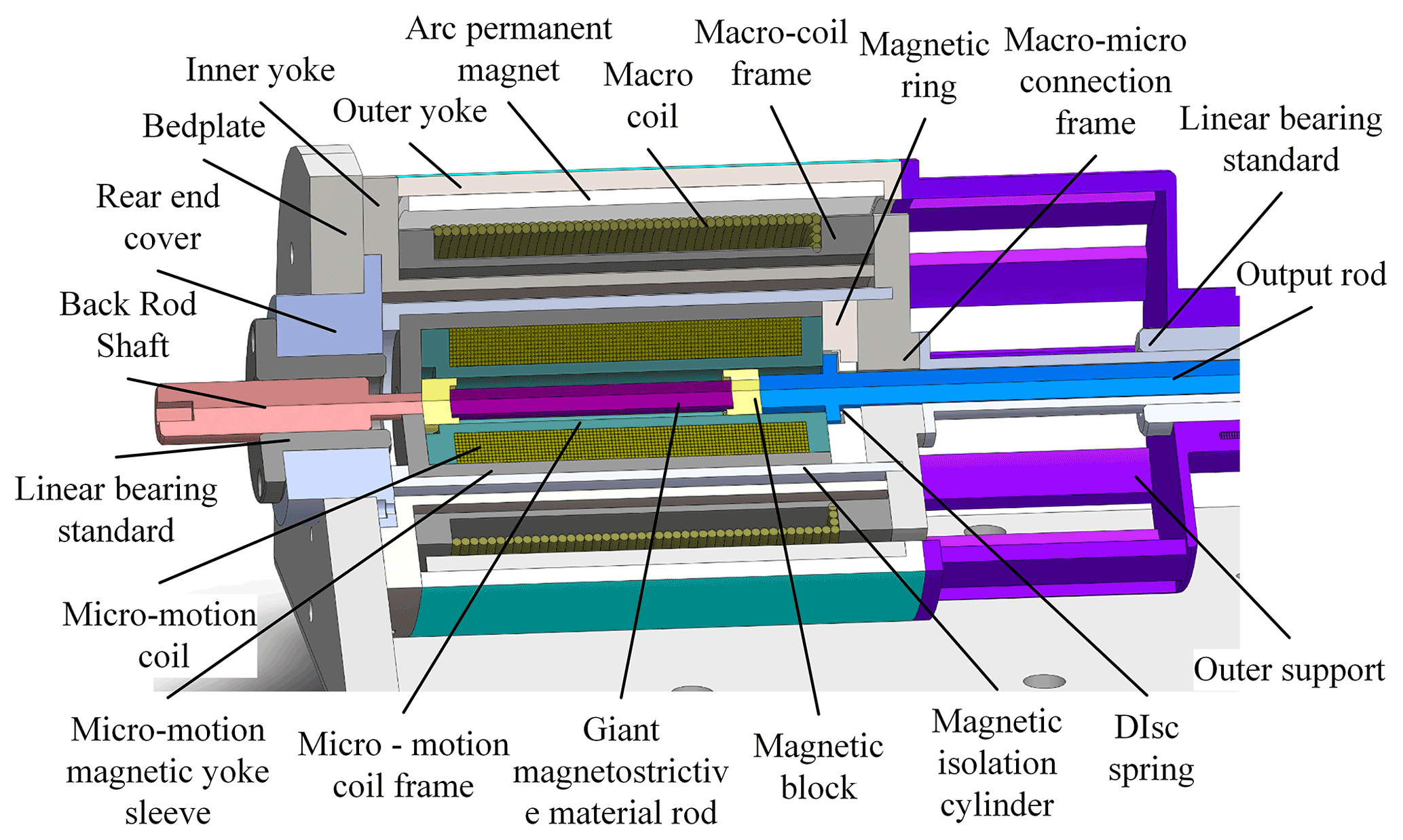
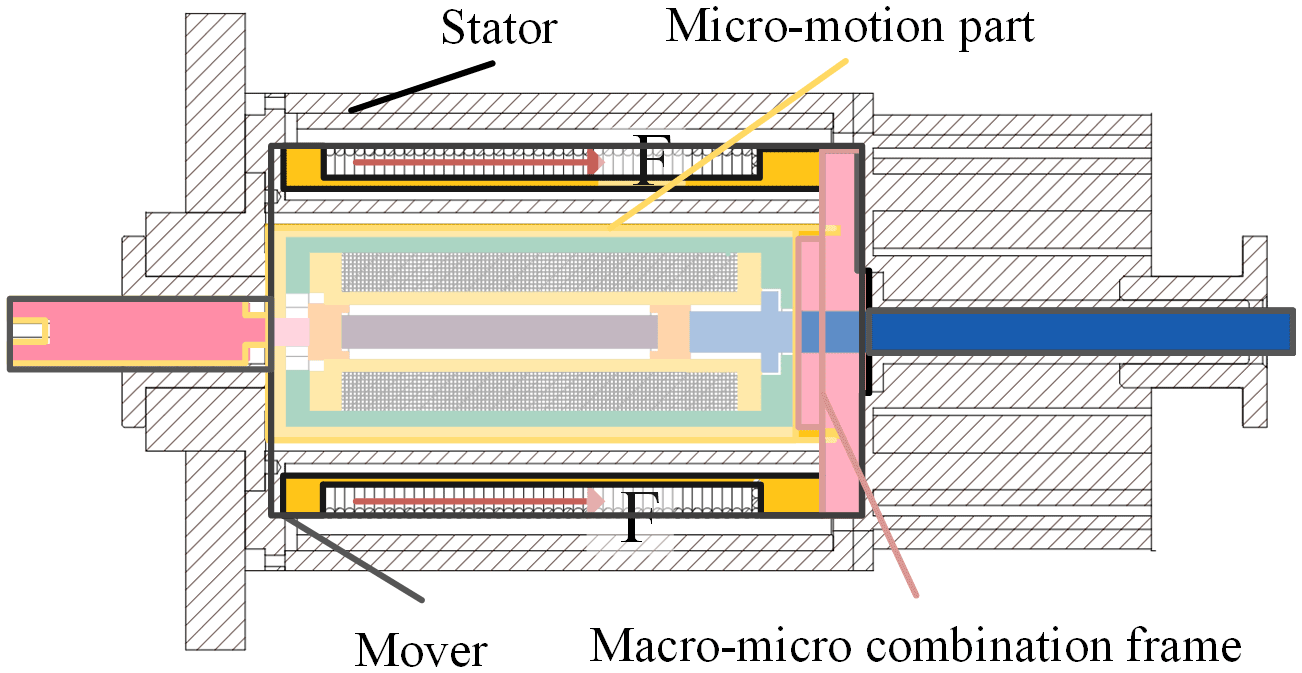
As shown in Fig. 1, the coaxial integrated macro–micro composite actuator proposed by our team is composed of macro-motion and micro-motion. The micro-motion part is connected with the macro-motion coil through the macro–micro combination frame, forming the mover, as shown in Fig. 2. The macro-motion part is obtained from the structural improvement of the moving coil voice coil motor (Shan et al., 2016), mainly including the external magnetic yoke, internal magnetic yoke, permanent magnet, macro-motion coil, skeleton, and macro–micro combination frame. Among them, the permanent magnet of the ring array provides a constant magnetic field for the macro-motion coil and forms a magnetic conduction circuit through the internal and external magnetic yokes. The working air gap of the macro-motion coil is the gap between the internal and external magnetic yokes. The macro-motion coil is electrified to generate ampere force, which promotes or attracts the mover to move outward or inward. Its main function is to realize the high-speed and large-stroke motion of the actuator. The micro-motion part is a giant magnetostrictive actuator, which is made based on the magnetostrictive effect of GMM (giant magnetostrictive material) (Yu et al., 2019), mainly including a magnetic isolator, micro-motion yoke sleeve, micro-motion coil, GMM rod, magnetizer block, and output rod. When its micro-motion coil inputs current, the excitation magnetic field acts on the GMM rod, which makes the GMM rod deform due to the magnetostrictive effect, promotes the output rod, and produces the micro-motion displacement. Its main function is to compensate for the positioning error of the macro-motion process with high precision.
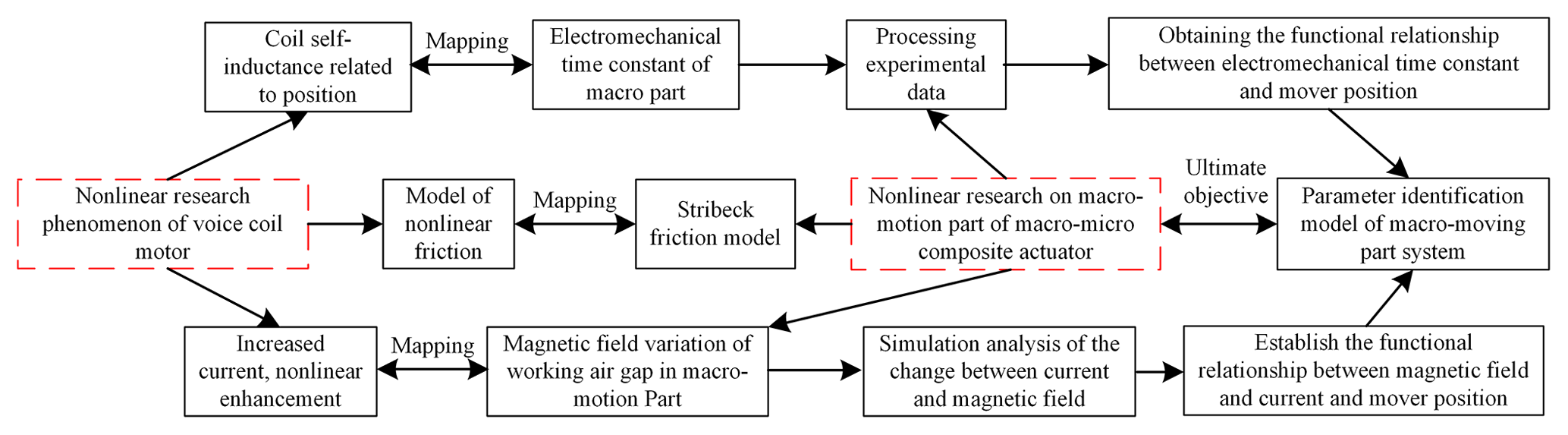
The micro-motion part of the macro–micro composite actuator mainly realizes high-precision error compensation, and the large-stroke characteristics of the actuator are mainly realized by the macro-motion part. Here, we only study the driving force model, static friction model, and dynamic model for the model of its macro-motion part. A schematic diagram of the study workflow is shown below.
2.1 Driving force model of macro-motion part
The working principle of the macro-motion part of the actuator is the same as that of the voice coil motor. At the working air gap, the permanent magnet provides a constant magnetic field source. The energized macro-motion coil is acted by the ampere force F to promote the mover movement, in which the ampere force F is the driving force of the macro-motion part, and its calculation expression is
where B is the magnetic field intensity generated by the macro-motion permanent magnet at the air gap, unit: Wb m−2; L is the effective length of each coil in a magnetic field, unit: mm; Ia is the working current of coil winding, unit: A; and N is the number of turns of the coil.
Since the uniformity of the magnetic field intensity B at the working air gap determines the stability of the driving force when the macro-motion part works, the magnetic field intensity distribution of the macro–micro composite actuator when the macro-motion coil is electrified is obtained through finite element simulation, as shown in Fig. 4.
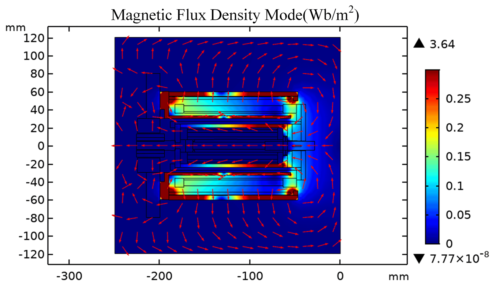
Figure 4Magnetic field distribution of macro-motion part of the macro–micro composite actuator.
It can be seen from the color distribution in Fig. 4 that when the macro-motion coil is energized, the magnetic flux density of the internal and external yokes of the macro-motion part is the highest, but the magnetic flux density of the middle section of the internal and external yokes is similar to that at the working air gap of the macro-motion coil, and the magnetic flux density value is low. The magnetic flux density of the micro-motion yoke is higher, but the magnetic flux density at the position of the GMM rod is the same as that in the air domain. It can be seen from the arrow direction in Fig. 4 that the internal and external yokes constitute the magnetic conduction circuit of the macro-motion part and provide the working magnetic field for the macro-motion part.
In order to further explore the magnetic field direction and uniformity of the magnetic field intensity at the working air gap of the macro-motion part, the moving axis system shown in Fig. 5 is established. When the working current of the macro-motion coil is 2 A, the magnetic field distribution map and isopleth map at the working air gap of the macro-motion part are shown in Figs. 6 and 7, respectively.
Figure 5Relationship curve between the axial magnetic field and axial displacement of the macro-motion coil.
It can be seen from Fig. 6 that the direction of the magnetic field intensity at the working air gap of the macro-motion part is radial, so the energized macro-motion coil generates an axial ampere force, thereby pushing the mover to move in a straight line along the axial direction.
From Fig. 7, it can be seen that the contour of radial magnetic flux density in the working air gap of the macro-motion part is gradually inclined. Therefore, the average value of the magnetic flux at the inner circle and outer circle generatrix of the macro-motion coil is taken as the magnetic flux density value at the working air gap. The simulation results show that when the working current of the macro-motion coil is (0–4) A, the magnetic flux density at the working air gap is shown in Fig. 8.
Figure 8 shows that the curve of the macro-motion coil when the working current of 0 A is flat, indicating that the uniformity of the magnetic flux density at the working air gap is the best at this time, but with the increase of the working current, the greater the change of the magnetic flux density at the working air gap, indicating that the macro-motion part is suitable for working in the small current driving state.
In order to obtain a more accurate driving force model, it is necessary to obtain the relationship between the magnetic field intensity at the working air gap and the position of the mover, and the working current of the macro-motion coil. By simulating the mover within the travel range of (0–50) mm, passing (0–4) A current to the macro-motion coil every 10 mm, the three-dimensional surface of the magnetic field intensity on the outer circular bus of the macro-motion coil is obtained as shown in Fig. 9.
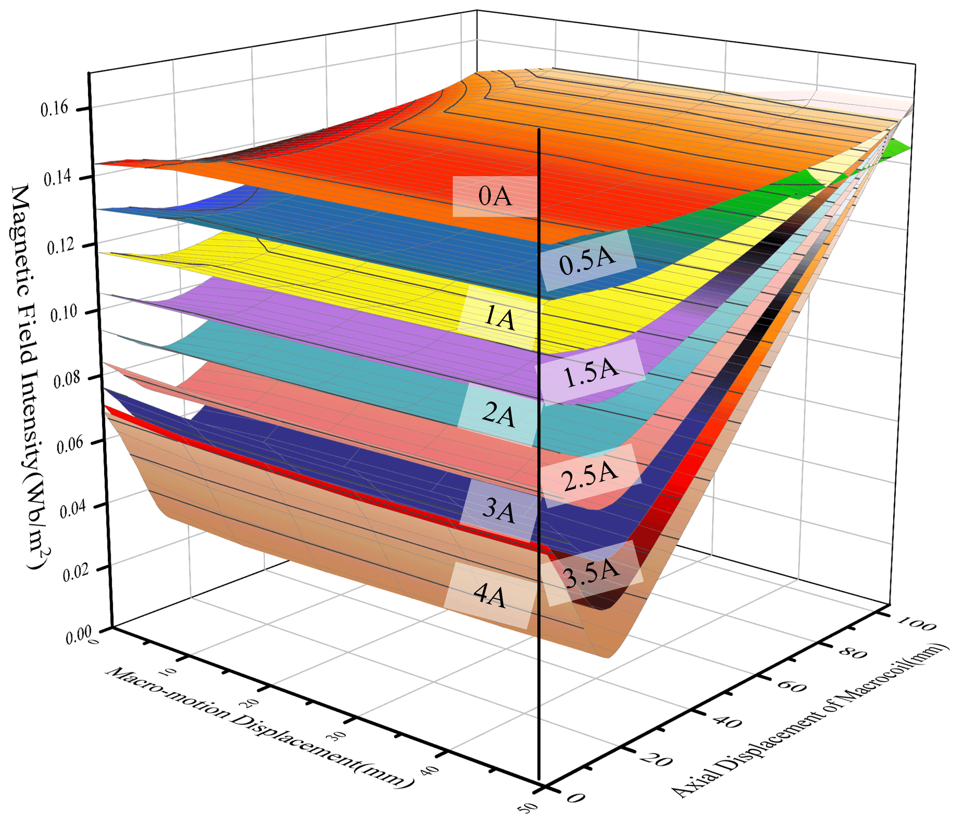
Figure 9The relationship curve between the magnetic field intensity at the working air gap of the macro-motion part and the position of the mover and the macro-motion current.
It can be seen from Fig. 9 that under different working currents, when the position of the mover changes, the magnetic field intensity at the working air gap of the macro-motion part is almost unchanged. With the increase of the coordinate value of the macro-motion coil bus, the magnetic field intensity at the working air gap first decreases and then increases. When the working current is (0–1) A, the magnetic field intensity changes gently, and when the working current is (3–4) A, the magnetic field intensity changes greatly. It can be seen that the magnetic field intensity at the working air gap is almost independent of the position of the mover and is greatly affected by the working current of the macro-motion coil.
Based on the above analysis, the magnetic field intensity at the working air gap of the macro-motion part is almost independent of the position of the mover. It is greatly affected by the working current of the macro-motion coil. The greater the working current, the greater the change of the magnetic field at the working air gap. Since the residual magnetic flux density of the permanent magnet used in the experiment cannot be accurately measured, and the residual magnetic flux density of the permanent magnet is set to 1.21 Wb m−2 in the simulation. The magnetic field intensity at the working air gap of the macro-motion part obtained by simulation is set as Bc, while the actual magnetic field intensity at the working air gap of the macro-motion part is set as K⋅Bc.
It can be seen from Fig. 9 that Bc is related to the current I and axial size of the macro-motion coil, so it is expressed as Bc(mL, I). Therefore, the calculation formula of ampere force generated by the macro-motion coil is rewritten as follows:
where Kt=KNL, K is a constant, unit: mm, Kt is the parameter to be identified, and mL is the position of the mover.
2.2 Static friction model of macro-motion part
The difference between the mover of the macro-motion part and the mover of the moving coil voice coil motor is that a micro giant magnetostrictive actuator is embedded in it, which increases the mass of the mover. Since the materials of the micro-motion yoke of the mover part and the internal and external yokes of the stator part are pure iron with high magnetic permeability, it is easy to be magnetized by the permanent magnet, resulting in magnetic force between the internal yoke and the micro-motion yoke, resulting in greater resistance of the mover part during startup. The magnetization curve of the internal yoke is obtained through simulation, as shown in Fig. 10.

It can be seen from Fig. 10 that the magnetization of the yoke in the macro-motion stator decreases with the increase of its axial distance, and the magnetization is directly proportional to the force on the micro-motion yoke, indicating that the force on the micro-motion yoke will decrease with the increase of the positive displacement of the mover. According to the principle of magnetic flux conservation, the simulation results show that when the mover is at the displacement of 0 mm, the axial force on the micro-motion yoke is about 1.89 N, and its force direction is opposite to the direction of macro-motion positive displacement.
By testing the experimental prototype, it is obtained that the static friction of the mover is about 10 N at the displacement of 0 mm and about 7 N at the displacement of 5 mm, indicating that the force received by the micro-motion yoke due to magnetization is related to the macro-motion displacement. By curve fitting the experimental measurement data, the expression of static friction is approximately obtained,
where fs is the static friction and mL is the position of the mover.
2.3 Kinetic model of macro-motion part
In order to obtain the self-inductance change model of the macro-motion coil (Manh and Chen, 2020; Luo et al., 2019), the equivalent circuit of the macro-motion coil is established, as shown in Fig. 11.
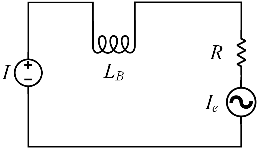
It is assumed that the control current of the macro-motion part is I, the equivalent resistance of the loop is R, the equivalent inductance is LB, and the working current in the loop is IA. When the macro-motion part works, the macro-motion coil moves to cut the magnetic induction line in the magnetic field to produce the induced current Ie opposite to the driving current, which is expressed as
where v is the speed of mover, unit: m s−1; B is the average magnetic field intensity at the working air gap of the macro-motion part, unit: Wb m−2; LB is the equivalent inductance of macro-coil; and Ke is the back electromotive force coefficient. Since the variation of magnetic field intensity B is small, the equivalent length and resistance of the macro-motion coil are constants, and the relative variation of the Ke value is very small, so it can be defined as a constant.
Then the loop equation of the macro-motion part is
In the series circuit, the inductance LB and the resistance R are equivalent to the first-order inertia link, the expression is as follows, Eq. (6):
where T is the time constant related to the self-induction of the macro-motion part.
When the current controller drives the macro-motion coil, it will cause the self-inductance of the macro-motion coil, and the self-inductance can affect the electromechanical time constant T of the macro-motion part. By analyzing the experimental data and combining the definition of the electromechanical time constant, it is obtained that the electromechanical time constant T is not a fixed value but related to the macro-motion displacement. Therefore, Eq. (6) is further equivalent to the following Eq. (7):
where is the parameter to be identified, and TL(mL) is a function of electromechanical time and mover position.
According to the working mode of the macro-motion part, the driving force F generated by the macro-motion coil not only overcomes the friction Fs generated during the movement of the mover but also needs to provide the driver with the inertial force FM and sliding friction Fc for acceleration and deceleration. Therefore, the kinetic model of the macro-motion part is
where M is the total mass of the macro-motion mover, unit: kg; mL is the macro-motion displacement, unit: mm; and Kc is the coefficient of viscous dynamic friction.
By quoting the Stribeck friction model, the expression of friction Ff describing the startup and movement of the macro-motion part is obtained as follows:
where Ff is the friction overcome during the operation of the macro-motion part, Kc is the sliding friction force, v is the speed of the mover, and vs is the maximum speed.
Therefore, the calculation formula of driving force F can be rewritten as
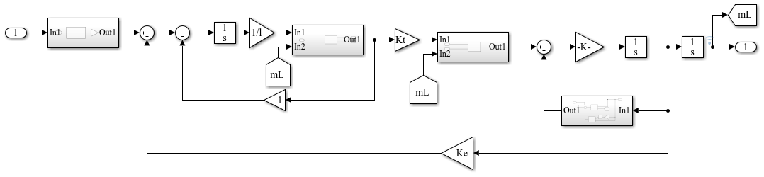
According to the mechanical equation and loop equation of the motor, the basic equations of the dynamic characteristics of the macro-motion part are obtained as follows: the Eq. (11) is transformed by Laplace transform and combined with the control principle of the actuator controller, and the kinetic model block diagram of the macro-motion part is obtained as shown in Fig. 12.
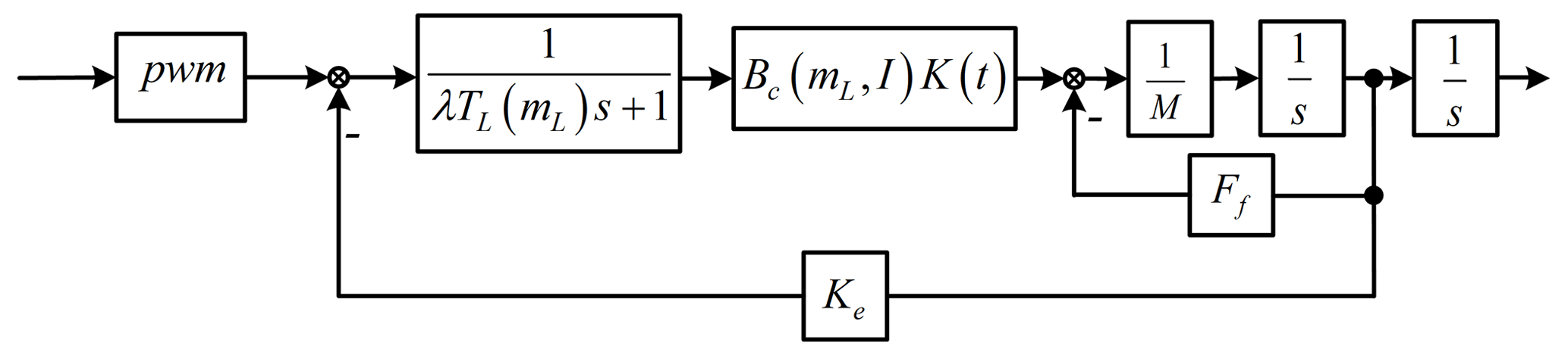
It can be seen from Fig. 12 that the parameters λ, Kt, Kc, and Ke in the kinetic model of the macro-motion part are unknown. It is necessary to identify the parameters according to the experimental data, where M is the mass of the mover and M is 4.5 kg by measurement.
3.1 Experimental data of parameter identification
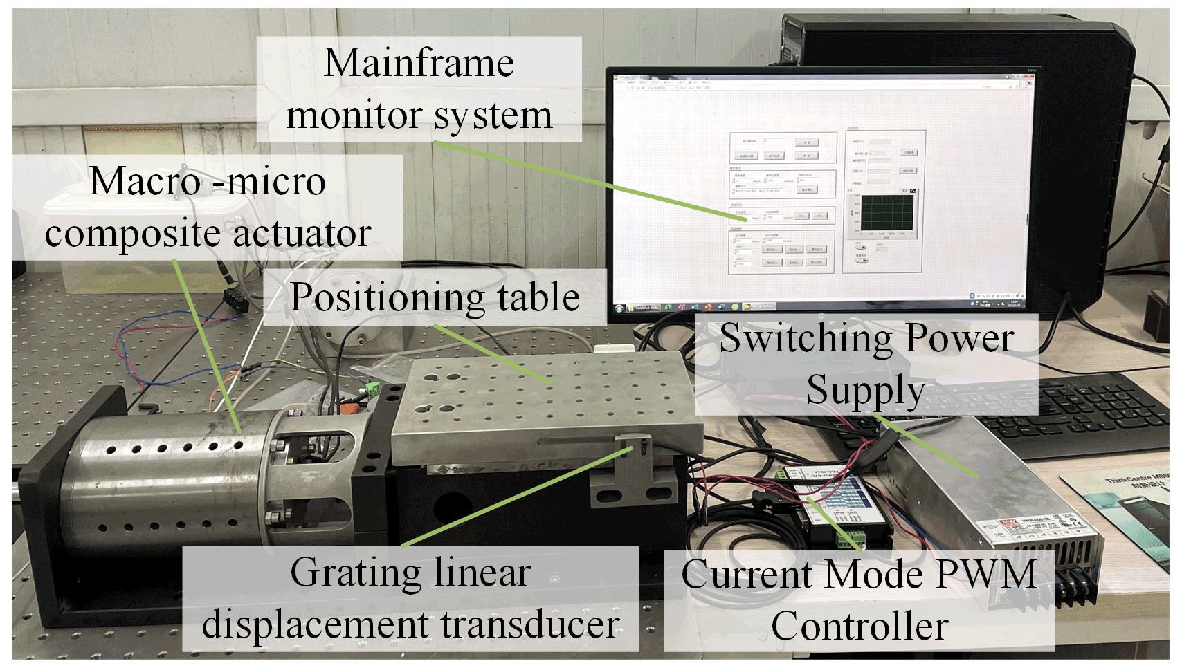
In order to obtain the parameter values of the model and verify the validity of the kinetic model, an experimental test platform of a macro–micro composite actuator is built, as shown in Fig. 13. It is mainly composed of a macro–micro composite actuator, positioning workbench, switching power supply, a grating displacement encoder, and current controller. The minimum resolution of the grating displacement encoder is 20 nm and the rise time of the current driver is 1 µs. LabVIEW is used as the upper computer control system and displacement display interface to adjust the output pulse of the current controller, drive the mover of the actuator, and display the real-time data collected by the grating displacement sensor.
During the experiment, the positioning workbench is placed at different starting positions. The variation curve of the output displacement of the positioning workbench with time is measured through the given current value, as shown in Fig. 14.
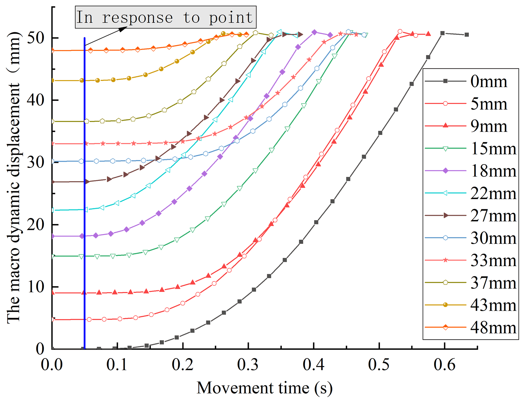
Figure 14Variation curve of macro-motion displacement with time at different starting positions.
It can be seen from Fig. 14 that the overall response time of the macro-motion part of the driver is about 50 ms, and when the positioning workbench reaches a certain speed value, its motion displacement changes approximately linearly with time. At the starting position of 9 and 30 mm, the starting time of the actuator is relatively longer, which may be due to the large change of friction and self-inductance of the macro-motion coil, which increases the electromechanical time constant of the macro-motion part.
Cubic spline interpolation is performed on the experimental data. After fitting with the least square method, the first-order derivation is carried out to obtain the maximum speed reached at different starting positions, as shown in Fig. 15.
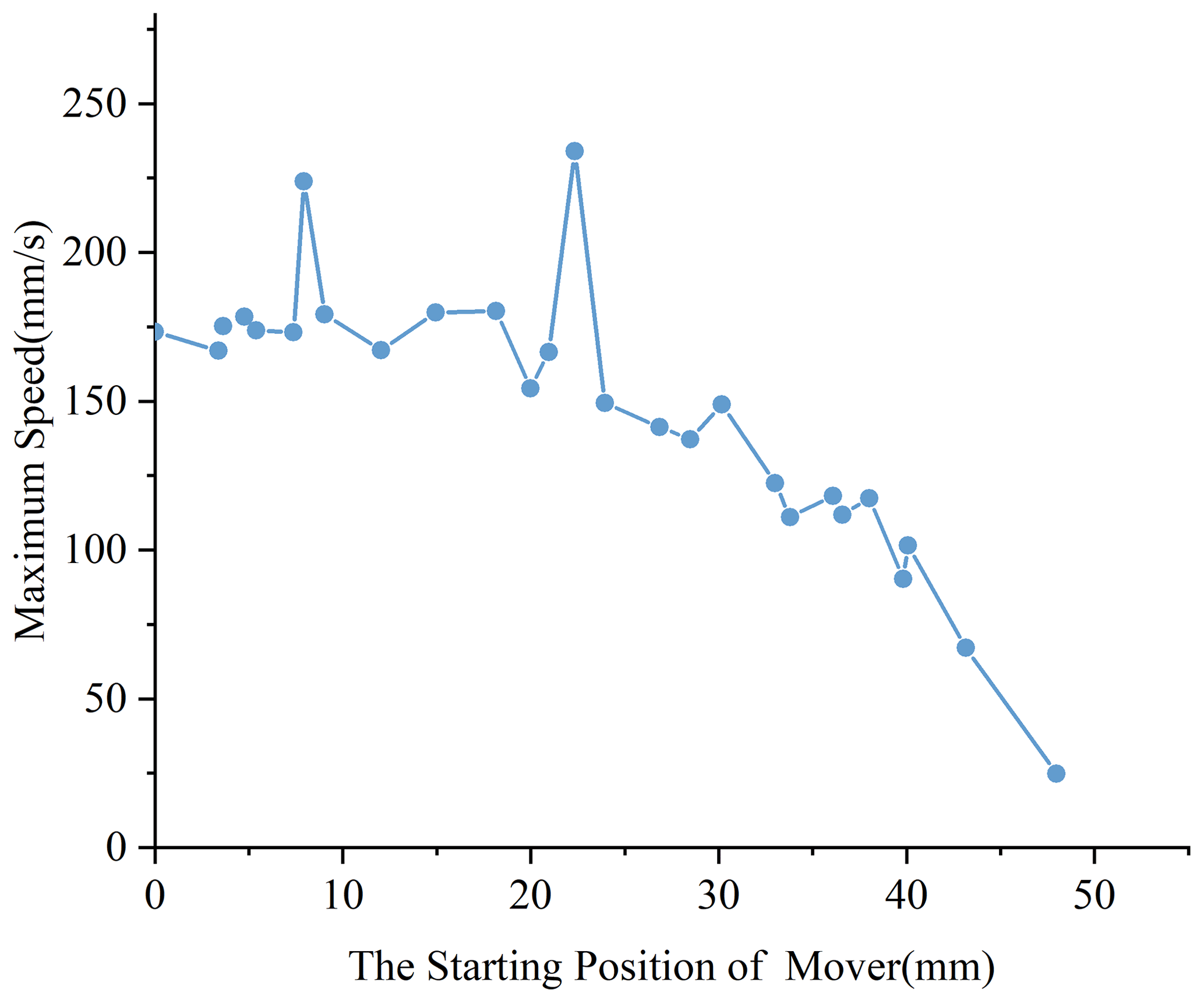
As can be seen from Fig. 15, the maximum value of maximum speed vs is 234 mm s−1. Combining the data in Fig. 15 with the experimental data, by solving the time corresponding to the maximum speed value and combined with the definition of electromechanical time constant, The function of electromechanical time and mover position is obtained as follows:
3.2 Parameter identification of model
As shown in Fig. 16, the parameter identification model block diagram of the macro-motion part is built by using the MATLAB/Simulink module. The relevant parameter values of the macro-motion part are obtained by using the parameter identification toolbox, as shown in Table 1.

The identified parameters are used for simulation and compared with the experimental data, and the comparison diagram between the simulation curve and the experimental curve is obtained, as shown in Fig. 17.

Figure 17Comparison curve of displacement simulation value and experimental value of the macro–micro composite actuator.
It can be seen from Fig. 17 that the displacement curve obtained by simulation using the parameters obtained by parameter identification is consistent with the changing trend of the displacement curve obtained by experimental measurement. The differences are as follows: in the initial response stage, the displacement of the actuator is almost unchanged. Combined with the simulation analysis of the magnetic field and current magnetic field at the working air gap of the mover in Fig. 8, the main reason may be due to the input current of the macro-motion coil gradually increasing, causing the magnetic field from the working air gap to decrease, resulting in a decrease in the driving force. When the mover is started, the mass of the mover part is larger than that of the general voice coil motor, and its static friction force is larger. Therefore, the displacement of the actuator changes little during the start-up stage of the mover. In addition, the overall displacement curve shows a non-linear trend. The reason may be that the self-inductance of the macro-motion coil prevents the increase of the current, which leads to the change of the driving force, and the nonlinear change of the friction force, which increases the nonlinearity of the macro-motion part. Therefore, when the macro-motion part is started, the current needs to be appropriately increased to increase the thrust value of the macro-motion coil. At the same time, combined with the analysis of the phenomenon that the middle value of the magnetic field intensity of the internal and external magnetic yokes is low in Fig. 4, the changing trends of the two curves are consistent, but the data do not overlap, indicating that the kinematics model of the macro-motion part needs to overcome friction and self-inductance. It is also necessary to consider the nonlinear influence of the eddy current loss generated between the macro-motion coil and the internal and external magnetic yokes due to the strong magnetic field environment and high-frequency pulse driving.
3.3 Model validation
To quantitatively compare the approximation degree between the identification model and the actual kinetic model, the model matching degree is calculated as follows according to the model matching index formula:
where Km is the model matching index; yi(t) is the actual output at the i sampling time of the actual structure; and Yi(t) is the calculation output of the identification model at i sampling times.
The closer the model matching value is to 100 %, the closer the identification model is to the actual structure. The matching degree between the identification model and the actual structure is 92.97 %. The results show that the calculated results of the identification model are consistent with the response of the actual structure.
In order to verify the identified transfer function model, the velocity curve is obtained according to the experimental data and compared with the simulation velocity curve, as shown in Fig. 18.

Figure 18Comparison curve of velocity simulation value and experimental value of the macro–micro composite actuator.
It can be seen from Fig. 18 that the velocity curve obtained by simulation is very close to the velocity curve obtained by experiment, which indicates that the established kinetic model of the macro-motion part can approximately characterize the nonlinear influence law of the macro-motion part, and provides a reference value for further design of the control system.
In this paper, the nonlinear characteristics of the kinetic model of the macro–micro composite actuator are analyzed, the driving force model and kinetic model of the macro-motion part are established, and the model parameters are identified by using the data measured on the experimental platform. The following conclusions are obtained:
-
The magnetic field distribution at the working air gap of the macro-motion part of the macro–micro composite actuator is relatively uniform, but it is related to the macro-motion displacement and the macro-motion coil current. The greater the current value, the lower the uniformity of the magnetic field, and the magnetic field intensity first decreases and then increases with the increase of the macro-motion displacement. At the same time, the self-inductance of the macro-coil decreases with the increase of the macro-motion displacement.
-
When the macro-motion part of the macro–micro composite actuator starts, the friction force changes complex. Although the friction model can approximately reflect the change of friction force, there are still some deviations, so it is necessary to establish a more accurate friction model.
-
The kinetic model of the macro-motion part can reflect the dynamic characteristics of the macro-motion part, the matching degree is 92.97 %.
-
This paper studies the nonlinear system of the macro–micro composite actuators and identifies the system parameters through magnetic field simulation and experimental data analysis. In the case of sufficient theoretical basis, it is also applicable to the research of other actuator systems. In the following research, the research group will refer to the nonlinear system established in the paper to reflect the dynamic characteristics of the macro–micro composite actuator, select an appropriate nonlinear control algorithm, and design the corresponding controller, so that the macro–micro composite actuator can achieve higher positioning accuracy.
The code in this research is available upon request by contact with the corresponding author.
The data set is derived from Fig. 14 in this paper.
All authors contributed to the study's conception and design. Material preparation, data collection, and analysis were performed by CY, YW, GW, ZX, YD, and KY. The first draft of the paper was written by YW and all authors commented on previous versions of the paper. All authors read and approved the final paper.
The contact author has declared that none of the authors has any competing interests.
Publisher’s note: Copernicus Publications remains neutral with regard to jurisdictional claims in published maps and institutional affiliations.
The authors gratefully acknowledge the support of the National Natural Science Foundation of China (NSFC).
This work is supported by the National Natural Science Foundation of China (grant no. 52105042), the Anhui Provincial Natural Science Foundation (grant no. 2008085QE214), the China Postdoctoral Science Foundation (grant no. 2019M652159), and the Anhui University of Science and Technology Graduate Innovation Foundation (grant no. 2021CX2053).
This paper was edited by Haiyang Li and reviewed by two anonymous referees.
Chen, Z., Yao, B., and Wang, Q.: Accurate motion control of linear motors with adaptive robust compensation of nonlinear electromagnetic field effect, IEEE-ASME T. Mech., 18, 1122–1129, https://doi.org/10.1109/TMECH.2012.2197217, 2012a.
Chen, Z., Yao, B., and Wang, Q.: Adaptive robust precision motion control of linear motors with integrated compensation of nonlinearities and bearing flexible modes, IEEE T. Ind. Inf., 9, 965–973, https://doi.org/10.1109/TII.2012.2225439, 2012b.
Consolation, L., Alessandro, R., Domenico, R., and Paolo, S.: A Statistical Approach for Improving the Accuracy of Dry Friction Coefficient Measurement, IEEE T. Instrum. Meas., 68, 1412–1423, https://doi.org/10.1109/TIM.2019.2905755, 2019.
Cui, J., Wang, S. Y., and Chu, Z. Y.: Feed-forward compensation control of nonlinear fiction for high acceleration motion system, Optics and Precision Engineering, 26, 77–85, https://doi.org/10.3788/OPE.20182601.0077, 2018.
Li, G. L., Li, H. L., Wang, Q. J., Ju, B., and Wen, Y.: Stribeck friction model parameter identification for a permanent-magnetspherical motor, Electric Machines and Control, 26, 121–130, https://doi.org/10.15938/j.emc.2022.04.013, 2022.
Liu, X., Huang, M., Xiong, R., Shan, J., and Mao, X.: Adaptive inverse control of piezoelectric actuators based on segment similarity, Transactions on Industrial Electronics, 66, 5403–5411, https://doi.org/10.1109/TIE.2018.2868011, 2018.
Luo, C. Y., Lin, Z. L., and Sun, J.: Design of linear voice coil motor with semi-closed structure, IET Electr. Power Appl., 13, 1574–1579, https://doi.org/10.1049/iet-epa.2019.0241, 2019.
Manh, L. N. and Chen, X. K.: MPC Inspired Dynamical output feedback and adaptive feedforward control applied to piezoactuated positioning systems, Transactions on Industrial Electronics, 67, 3921–3931, https://doi.org/10.1109/TIE.2019.2916356, 2020.
Merit, B., Lemarquand, V., Lemarquand, G., and Dobrucki, A.: Motor nonlinearities in electrodynamic loudspeakers: modeling and measurement, Arch. Acoust., 34, 579–290, https://doi.org/10.1016/j.apacoust.2007.12.001, 2009.
Nie, L. L., Luo, Y. L., and Gao, W.: Rate-dependent asymmetric hysteresis modeling and robust adaptive trajectory tracking for piezoelectric micropositioning stages, Nonlinear Dynam., 108, 2023–2043, https://doi.org/10.1007/s11071-022-07324-7, 2022.
Shan, G. Q., Li, Y. Z., Zhang, Y. X., Wang, Z. Y., and Qian, J. Q.: Experimental characterization, modeling and compensation of rate-independent hysteresis of voice coil motors, Sensor Actuat. A-Phys., 251, 10–19, https://doi.org/10.1016/j.sna.2016.09.030, 2016.
Tao, K. and Chu, J.: Sensorless Algorithm of high-speed permanent magnet synchronous motor based on online motor parameters correction, Electric Machines & Control Application, 49, 1–15, https://doi.org/10.12177/emca.2021.158, 2022.
Vansompel, H., Leijnen, P., and Sergeant, P.: Multiphysics analysis of a stator construction method in yokeless and segmented armature axial flux PM machines, IEEE T. Energy Conver., 34, 139–146, https://doi.org/10.1109/TEC.2018.2862622, 2019.
Wavre, N. and Thouvenin, X.: Voice-coil actuators in space, Sixth European Space Mechanisms and Tribology Symposium, 374, 227–231, 1995.
Yu, C. F., Wang, C. L., Xie, T., and Yang, L. J.: Development of drive system of high-performance micro positioning worktable based on giant magnetostrictive material, J. Mech. Eng., 55, 136–134, https://doi.org/10.3901/JME.2019.09.136, 2019.
Yu, A. B., Liu. L., Kan, Z. Z., and Zhang, C. J.: Initial position identification of PMSM with filterless high-frequency pulse signal injection method, Transactions of China Electrotechnical Society, 36, 801–809, https://doi.org/10.19595/j.cnki.1000-6753.tces.191818, 2021.
Yu, C. F., Wang, Y., Chen, Z., Xiong, M. J., Shi, R., and Xiao, Z. H.: Experimental study and magnetic circuit modeling analysis of coaxial integrated macro-micro composite actuator, Proceedings of the CSEE, 42, 6083–6093, https://doi.org/10.13334/j.0258-8013.pcsee.211129, 2022.
Zhang, G. S. and Li, S. Q.: A new adaptive iterative learning algorithm based on a high-order internal model, Sci. Technology, 55, 480–488, 2022.
Zhang, Q., Wang, H., and Liu, C.: MILM hybrid identification method of fractional order neural-fuzzy Hammerstein model, Nonlinear Dynam., 108, 2337–2351, https://doi.org/10.1007/s11071-022-07303-y, 2022.
Zhang, X. H., Zhao, J. W., Wang, L. J., Hu, D. B., and Wang, L.: High precision anti-interference Online multiparameter estimation of PMSLM with adaptive interconnected extend Kalman observer, Proceedings of the CSEE, 42, 4571–4580, https://doi.org/10.13334/j.0258-8013.pcsee.210755, 2022.
Zhu, H., Chee, K. P., and Tat, J. T.: A flexure-based parallel actuation dual-stage system for large-stroke nanopositioning, IEEE T. Ind. Electron., 64, 5553–5563, https://doi.org/10.1109/TIE.2017.2677306, 2017.
Zhu, M. X., Wang, X., Sun, H. Y., Ci, W. Y., and Yao, W. X.: Proportional resonance control of permanent magnet brushless DC motor, Electric Drive, 49, 14–19, https://doi.org/10.19457/j.1001-2095.dqcd18680, 2019.
- Abstract
- Introduction
- The model of the macro-motion part of the macro–micro composite actuator
- Parameter identification of macro–micro composite actuator model
- Conclusion
- Code availability
- Data availability
- Author contributions
- Competing interests
- Disclaimer
- Acknowledgements
- Financial support
- Review statement
- References