the Creative Commons Attribution 4.0 License.
the Creative Commons Attribution 4.0 License.
 | 10 Oct 2022
Dynamic modeling and experiment of hind leg swimming of beaver-like underwater robot
Zhenyu Wang
Jiajun Tu
Donghai Wang
When the beaver-like underwater robot is swimming, its hind legs provide the main propulsion force for the body, which is the source of power for the robot's movement. Hind leg swimming dynamics is the basis for analyzing the generation and change of propulsion force during the robot swimming process, which directly determines how the robot swimming trajectory is planned. However, there are few researches on the swimming dynamics of the hind leg of a beaver-like underwater robot. This paper proposes a rigid–liquid fusion dynamics modeling method, which simplifies the swimming dynamics of hind legs of beaver-like robot to hydrodynamics of webbed feet and rigid body dynamics of thighs and calves. The hydrodynamics of the bendable webbed foot is established based on the integral hydrodynamics method, and the rigid body dynamic model of the thigh and calf is constructed using the Newton–Euler method. Through the force transmission, the overall swimming dynamic model of the hind leg is established, and the propulsion and lift force of the hind leg to body are obtained. The ANSYS Fluent simulation of the movement of robot's hind leg and underwater single-leg swimming experiments verify the correctness and effectiveness of the dynamics model. Comparing the theory, simulation, and experimental results of the propulsion and lift force of the robot's hind legs under bionic swimming, increased amplitude swimming, and reduced amplitude swimming, it further verifies the correctness of the proposed rigid–liquid fusion dynamic modeling method, and proves the superiority of the robot's bionic swimming trajectory. This study can provide new ideas for the leg dynamic modeling of underwater swimming robots with bendable webbed feet, and lay a theoretical foundation for exploring the swimming mechanical process of underwater robots.
- Article
(4391 KB) - Full-text XML
- BibTeX
- EndNote


With the development of ocean exploration, more and more attention has been paid to the application of underwater robots. Among them, the underwater bionic robot has a good movement ability by imitating the structure and motion mode of underwater organisms, which effectively improves the efficiency of the underwater robot and the adaptability to complex environments.
Inspired by diving beetles, Kim et al. (2014) developed a bionic hexapod underwater beetle robot that can swim and walk underwater. The two feet are designed with web-like structures to achieve efficient underwater propulsion. Taking the squid as the bionic object, Tiandong et al. (2019) designed a squid-like robot with double undulating fins. By symmetrically installing two modular undulating fins, the robot achieved better low-speed motion stability and anti-disturbance performance. Inspired by manta rays, Zhang et al. (2018) developed a manta-like robot with flexible pectoral fins, which successfully simulated the real flexible deformation of pectoral fins through the effective combination of flexible mechanism and rigid support.
The excellent movement ability of underwater bionic robots is realized through motion control, and the kinematics and dynamics model of robots usually establish the foundation of robot motion control. In 1994, Healey (1994) put forward the modeling method for the dynamics of underwater vehicles, and established the propulsion force and lift force model when the propeller rotates. In 2008, Richards (2008) proposed a verification model based on the frog-like robot, which could predict the swimming speed of the robot according to the foot kinematics. In 2003, Johansson and Norberg (2003) studied the effect of triangular flippers on a hydrodynamic lift in birds. In 2015, Yang et al. (2015) developed a study of an amphibious snake-like robot, and derived the analytical kinematics equations and planned the typical gait. In 2019, inspired by the efficiency and versatility of fish swimming, Moreno Mayz et al. (2019) proposed two dynamic models, one linear and time-invariant (LTI) and one non-linear based on the dynamics of conventional submarines. At present, most of the dynamic models of the underwater bionic robot only analyze the force of a single driving structure, which is suitable for the dynamic modeling of the robot connected with a single joint. However, this dynamic modeling method cannot meet the requirements for the robot imitated by beavers, frogs, etc., with webbed feet and multi-joint legs. Therefore, it is necessary to further study the dynamic modeling method of the robot with webbed feet and multi-joint legs.
In this paper, the swimming dynamics of a beaver-like robot with webbed feet is studied. A rigid–liquid fusion dynamic modeling method for the multi-joint hind legs of the robot is proposed. The structure of the paper is as follows: Sect. 2 studies the hind leg kinematics model of the beaver-like underwater robot. In Sect. 3, the rigid–liquid fusion dynamic modeling theory for the swimming process of the hind leg of a beaver-like robot is analyzed. In Sect. 4, the swimming dynamics of the hind leg is verified by simulations and experiments. Section 5 summarizes the study and draws the conclusion.
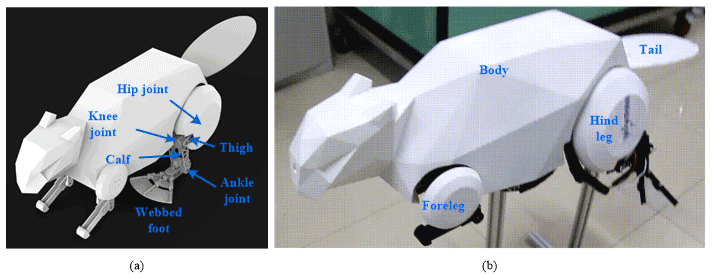
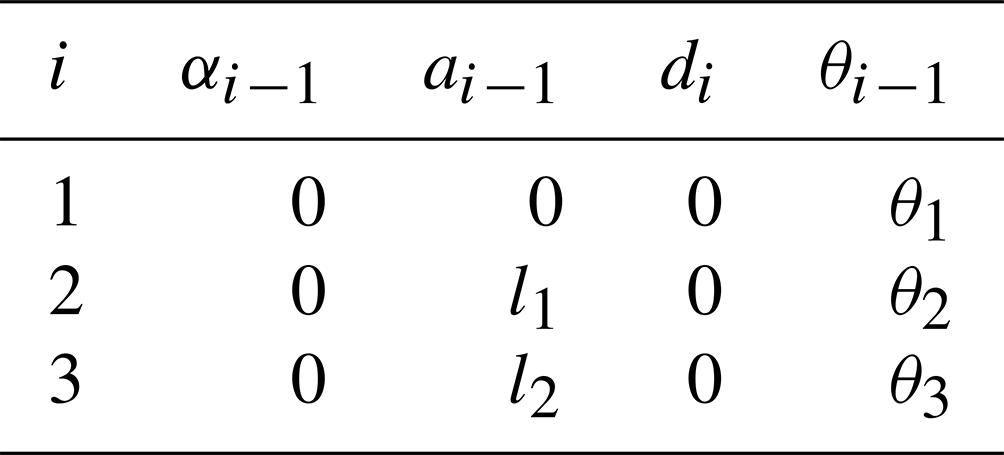
The beaver-like underwater robot contains a body, two forelegs, two hind legs, and a tail. The hind legs of the robot are articulated with two links, including the thighs, calves, and webbed feet, and are connected by the hip, knee, and ankle joints (as shown in Fig. 1). The webbed feet of the robot imitate the structure and the expanding–contracting movement mode of the beaver (Azarsina et al., 2016; Gang et al., 2021a, c). The webbed foot is driven by wire ropes to fully open when the robot paddles to generate sufficient propulsion force and it contracts when the leg returns to minimize the water resistance (Gang et al., 2021b; Alvarado, 2011). This can effectively improve the swimming ability of the beaver-like underwater robot. Taking the hind legs of the beaver-like underwater robot as the research object, the D–H kinematics modeling method was used to establish the coordinate system {0}, {1}, {2}, {3} at each joint, where the coordinate system {0} is the fixed coordinate system, and coordinate systems {1}, {2}, and {3} are the joint coordinate systems, respectively (as shown in Fig. 2). The D−H parameters of the hind legs of the robot are shown in Table 1.

Table 1D−H parameters of hind legs of beaver-like underwater robot.
Since the centroid of each leg, including the webbed foot, is mainly located at the end of the servo motor, it is assumed that the centroids of the thigh, calf, and webbed foot are located at the hip, knee, and ankle joint. Based on the established D−H model and Newton–Euler method, the angular velocity, angular acceleration, acceleration, centroid acceleration, and inertia force of hip, knee, and ankle joint are respectively obtained as follows:
where ; the inertia moment is 0 since the mass center is located at the end.
3.1 Kinematics and hydrodynamic modeling of webbed foot
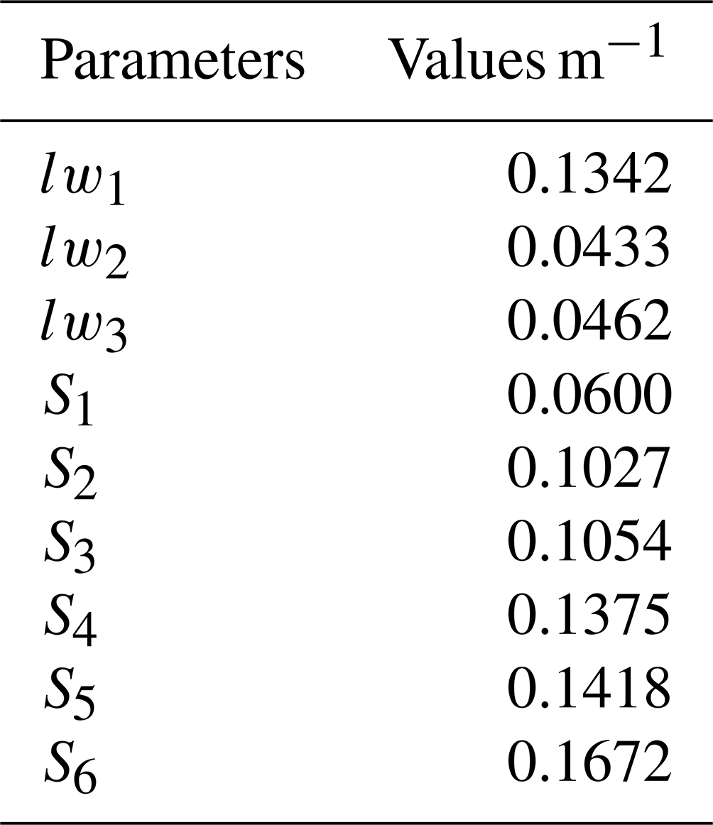
As shown in Fig. 3, the webbed foot of the beaver-like underwater robot is divided into three sections based on the connected joints, and the hydrodynamic force on each section can finally be obtained by calculating the hydrodynamic force on the whole webbed foot. The hydrodynamics on the webbed foot include propulsion force, lateral force, additional mass force, and other unknown interference forces, etc. In this paper, the influence of water propulsion on the webbed foot will be mainly considered in the hydrodynamics of the beaver-like underwater robot. The dimension parameters of the webbed foot are shown in Table 2.
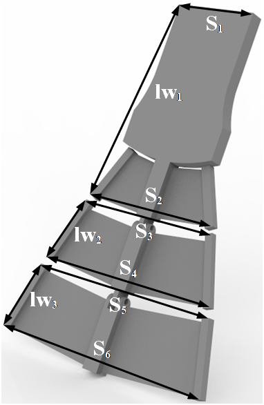
Table 2The dimension parameters of the webbed foot of the beaver-like underwater robot.
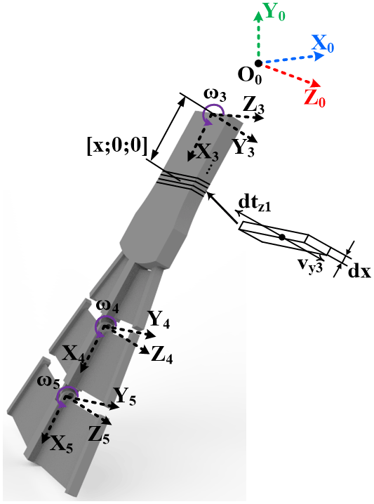
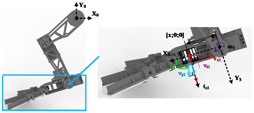
As shown in Fig. 4, a differential segment is chosen from the first section of the webbed foot, its length is dx, and the position in the coordinate system X3Y3Z3 is . The hydraulic is related to the velocity vector perpendicular to the webbed foot (as the parameter vy3 shown in Fig. 4), and the resulting hydraulic propulsion is in the opposite direction to the velocity vector, as the parameter dtz1 shown in Fig. 4.
First, the velocity vector of this differential segment in the ankle coordinate system is
Based on the known hind leg size and transformation matrix, the velocity vector of this segment in the knee joint coordinate system is calculated by the transfer formula,
Similarly, the velocity vector of this segment in the hip joint coordinate system can be obtained,
Through the transformation matrix, the velocity vector expressed in the hip joint is converted to the world coordinate system, which is expressed as
The velocity vector 0Vx1 of the first section obtained by the above formula is its velocity vector relative to the world coordinate system, and the included angle formed by the first knuckle in the angle coordinate system X3 is αx3. As shown in Fig. 5, the projection method is used to calculate the velocity vt1 perpendicular to the direction of the webbed foot.
The hydrodynamic propulsion formula of the webbed foot is , where CT is the propulsion coefficient with a value of 1.112; ρ is the density of water; V is the vertical relative velocity between the webbed foot and the flow field; and S is the area of the webbed foot. The differential propulsion is expressed as , and the propulsion on the three sections of the foot is obtained by integral, respectively, and they are expressed as
where the expression of vt is ; ;, in which αx3, αx4, and αx5 are the residual angles of the acute angle between the webbed foot (x3), knuckles 1(x4), and 2(x5) and the body coordinate system x0, respectively.
Since the webbed feet are bendable components driven by steel wire rope, they can be regarded as rigid bodies at every moment in the calculation, and the mass center of the webbed foot is mainly concentrated on the servo motor of the ankle joint, so the moment of inertia is 0, and the hydrodynamic force Fw on the webbed foot is
3.2 Overall dynamics modeling in hind leg swimming
Rigid body dynamics and hydrodynamics are combined in the hind leg swimming of the beaver-like underwater robot. Webbed feet are mainly affected by hydrodynamics, while thighs and calves are mainly affected by rigid body dynamics. Therefore, the overall dynamics of hind legs can be simplified as a fusion process of the hydrodynamics of webbed feet and rigid body dynamics of thighs and calves, specifically as follows: the thigh, calf, and webbed foot are equivalent to linkages, and the hydrodynamic force of the webbed foot and the rigid body force of the thigh and calf are transferred to the hip joint at the root of the hind legs through the equivalent linkages, and the force of the hind legs on the robot is obtained.
First, combining Eqs. (8)–(13) and the Newton–Euler formula, the force vector on the ankle joint is calculated as
where Fw is the hydrodynamic resultant force on the webbed foot.
Then, the force vectors of knee joint and hip joint are obtained by recursion as follows:
Thus, 1f1 can obtain the force of hind legs on the robot through the transformation matrix,
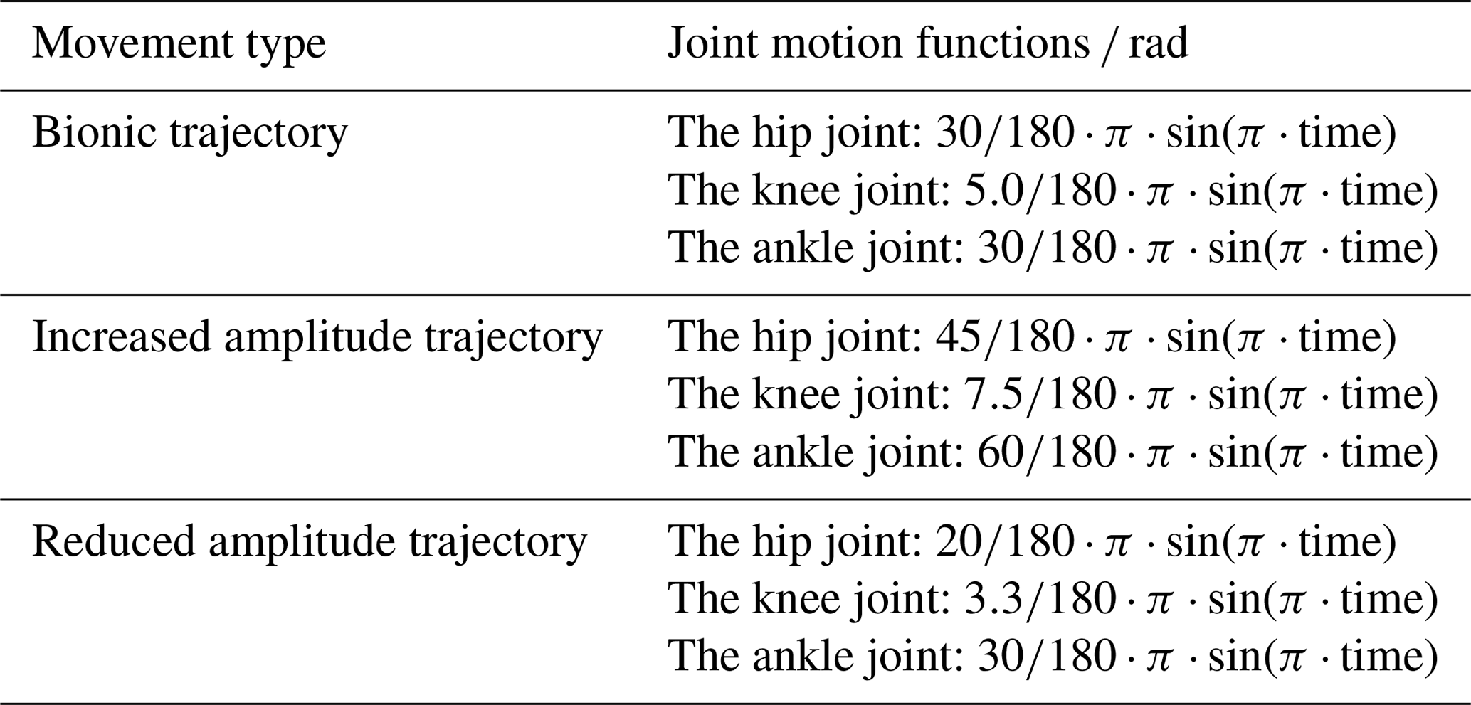
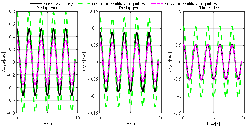
The underwater motion simulation and experiment of the hind leg of the beaver-like underwater robot are carried out with three kinds of motion trajectories, which are bionic, increased amplitude, and reduced amplitude trajectory. Increased and reduced amplitude motion trajectories are respectively obtained by increasing and decreasing the motion amplitude based on the bionic motion trajectory. The motion functions of three trajectories are shown in Table 3, and the motion angle curves of three joints in three motion modes are shown in Fig. 6. Based on the software ANSYS Fluent, the underwater motion simulation of the hind legs of the beaver-like underwater robot was carried out, and the force of a hind leg on the robot was obtained (Gang et al., 2021a). At the same time, the hind leg swimming process of the beaver-like underwater robot is tested. Specifically, the hip of the hind leg is fixed on the experimental pool, and the force data of the hind leg in the swimming is measured through the six-axis force sensor ME K6D.
Table 3Motion function of hind legs of beaver-like underwater robot.
4.1 Simulation of hind leg swimming of beaver-like underwater robot
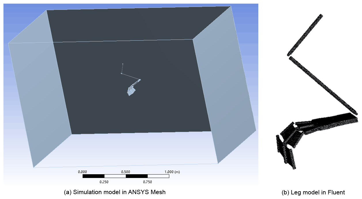
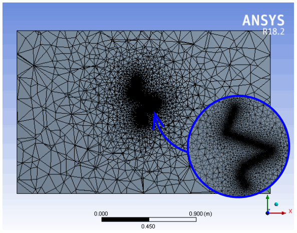
The underwater movement of the hind legs of the beaver-like underwater robot is simulated by ANSYS Fluent. When the hind legs of the beaver-like underwater robot are paddling, the hydrodynamic force of the webbed foot is much greater than that of the legs. Thus, the leg model is simplified as link connection in the simulation (as shown in Fig. 7a), and the surrounding plane is four walls of the flow field. Figure 8 shows the simulation model after meshing. The motion grid technology is used to simulate the motion of the robot's hind legs, and the motion of each joint is defined by the DEFINE_CG_MOTION macro. The calculation model adopts a modified model. Since the initial setting of the flow field is a no-flow flow field, the inlet and outlet are all set as pressure outlets. In the simulation, the hip joint of the hind leg of the robot is fixed. The joints of the hind leg move according to the motion functions under three preset motion trajectories, and the force data of the hip joints in X and Y directions are obtained, which correspond to propulsion and lift force respectively (as shown in Fig. 7b).
4.2 Hind leg swimming experiment of beaver-like underwater robot
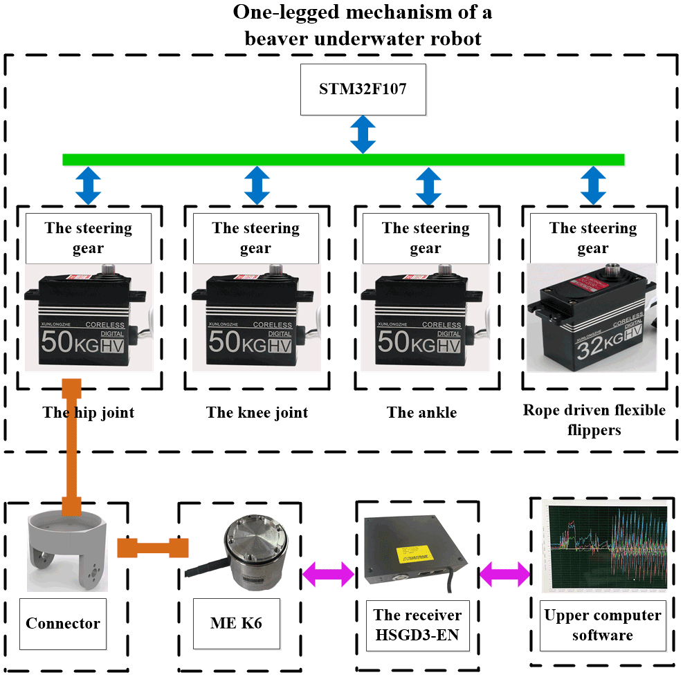
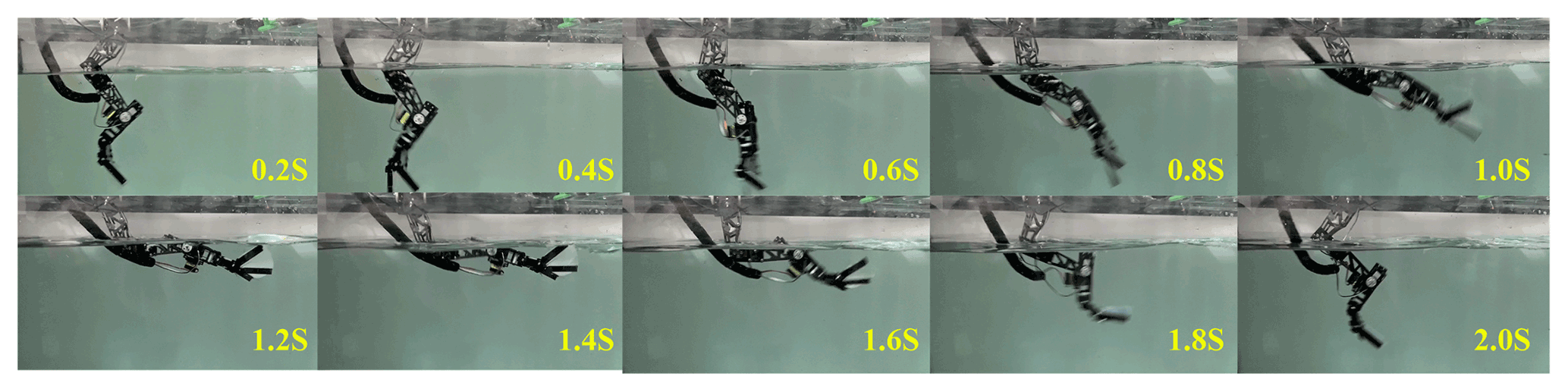
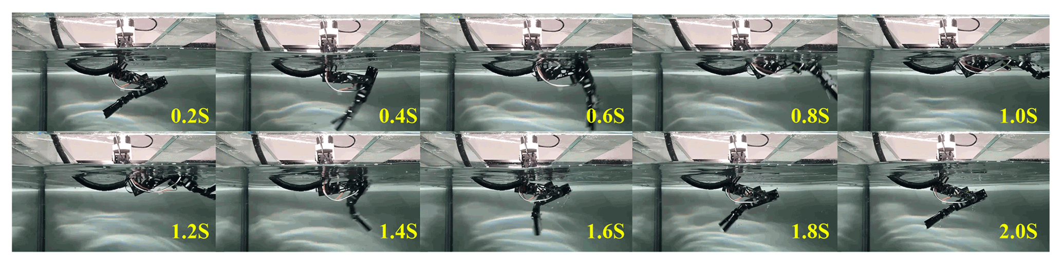
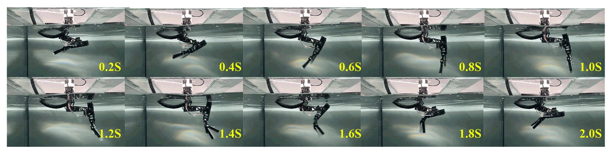
The underwater motion experiment of the hind leg of the beaver-like robot was carried out in a pool (length, width, and height: 2 m × 1 m × 1.2 m). The experimental system is shown in Fig. 9, which includes the hind leg drive system, the six-axis force sensor system ME K6D, and the mechanical connecting mechanism (Wang et al., 2019). Each joint servo motor of the hind leg is controlled by STM32F107. The six-axis force sensor system ME K6D collects the force data of the robot's hind leg, and receives and displays data information through the upper computer. The maximum range is 200 N/5 Nm, and the acquisition frequency is 10 Hz. The hind leg of the robot is immersed in water, and the hip joint is fixed with the force sensor through the connector and placed above the water. The force sensor is connected with the acrylic plate fixed above the pool to ensure the movement stability of the robot. The hind leg of beaver-like underwater robot paddles according to three kinds of motion trajectories, and the force sensor collects the propulsion and lift force generated during the swimming of the hind leg in real time (Kim, 2014). Figures 10, 11, and 12 respectively show a single period experiment of the hind leg with bionic, increased amplitude, and reduced amplitude trajectory.
4.3 Result analysis
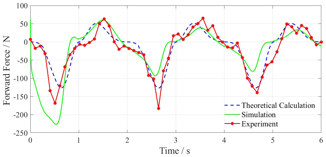
Through theoretical calculations, Fluent simulation, and underwater experiments, the result curves of three periods with total 6 s are obtained in which the experimental lift results have been subtracted from the gravity of the connector. Figures 13 and 14 show the propulsion and lift force curves of swimming with bionic motion trajectory. Figures 15 and 16 show the resultant curves of swimming with increased amplitude motion trajectory. Figures 17 and 18 show the resultant curves of swimming with reduced amplitude motion trajectory. In the forward force curve, the negative value is the propulsion force, and the positive value is the resistance force. In the lift curve, the positive value is the positive lift force, and the negative value is the negative lift force (Jizhuang, 2017; Gang et al., 2020).
4.3.1 Experimental result analysis of hind leg swimming with bionic motion trajectory
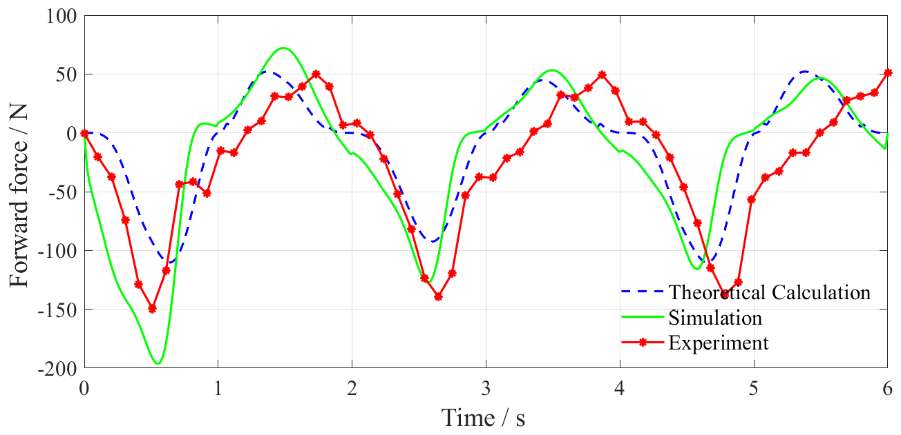
Figure 12 shows the forward force curve of swimming with bionic motion trajectory and we can see the following:
-
In the first period, the trends of the three curves are similar, but the difference in amplitude is large. The peak values of the propulsion force in the theoretical calculation, simulation, and experiment are about −112, −197, and −150 N which appear at the time 0.6, 0.5, and 0.5 s. The peak values of resistance force are 51, 71, and 50 N at the time 1.4, 1.5, and 1.7 s, respectively.
-
In the second period, the theoretical calculation results are almost consistent with the simulation results. The theoretical calculation, simulation, and experimental results of the propulsion force achieve the largest values −112, −124, and −142 N at the time of 2.6, 2.5, and 2.6 s. The peak values of resistance force are 51, 51, and 50 N at the time of 3.4, 3.5, and 3.8 s. Certain phase differences exist in the experimental, simulation, and theoretical calculation results.
-
In the third period, the largest values of propulsion force in theoretical calculation, simulation, and experiment are about −112, −115, and −146 N and they appear at the time of 4.6, 2.5, and 4.7 s, respectively. The peak values of resistance force are 51, 48, and 50 N at the time of 5.4, 5.5, and 6 s, respectively. The theoretical model results are in good agreement with the simulation results, and the phase difference between the peak values of the experimental result and the others increases.
-
As the period increases, the peak value of the simulation result gradually decreases. According to the results, the theoretical calculation, simulation, and experimental results in the first cycle show that the ratios of the propulsion and resistance force are 2.2, 1.8, and 3.0, respectively, which proves that the beaver-like underwater robot with the bionic motion trajectory can produce effective propulsion.
The reasons for the above differences are as follows: (1) in the experiment, the hydrodynamic force of the leg and servo motors will have an effect on the force of the hip joint at the same time, but it is reduced and ignored in the simulation and theoretical calculations. This results in the difference of peak values of propulsion force being large in the first period. (2) With the period increasing, the peak values of the simulation and the experiment result gradually decrease. The main reason for this phenomenon is that the hydrodynamic force received by the webbed foot is mainly determined by the velocity difference between the foot and the surrounding flow field. In the simulation and experiment, due to the movement of the legs, the surrounding flow field will have a certain speed, which reduces the velocity difference with the foot. (3) In the experiment, the operation deviation of the underwater servo motor, the installation error of the mechanical structure, and the pulling effect of the control cable on the structure cause the differences between experimental results and theoretical calculation and simulation results.
By comparison, the change trends and peak values of the three curves are relatively similar, which proves that the rigid–liquid fusion dynamics model is correct for the propulsion calculation of the single-legged beaver-like underwater robot.
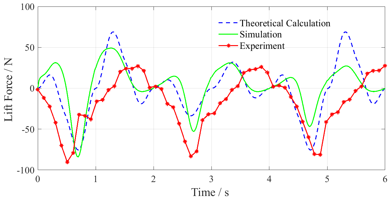
Figure 13 shows the lift curve of swimming with bionic motion trajectory and we can see the following:
-
Theoretical calculation and simulation results have two maximums and two minimums in each period. The results of the theoretical calculation are the same during the cycle, and the extreme values of the lift forces are about 16, −76, 69, and −19 N, the four extreme values appear in a period of 0.2, 0.7, 1.3, and 1.8 s, respectively. The simulation results gradually decrease with the period increasing. In the first period, the four extreme values are 31, −84, 49, and −4 N, respectively, and decrease to 13, −47, 27, and −3 N in the third period. The four extreme values appear at a relatively fixed time in each period which are about 0.3, 0.7, 1.2, and 1.8 s.
-
The experimental results are quite different with the theoretical calculation and simulation results. The amplitude of the maximum negative lift force is about −89 N, but the number and amplitude of its extreme values and the change trend are quite different. For example, in the first period, the theoretical calculation and simulation results have a positive lift force in the first 0.2–0.3 s, but the experimental results show a decreasing trend from the beginning to the maximum value of the negative lift force, and the maximum value appears at 0.5 s, and the phase difference with the other two results is about 0.2 s. Meanwhile there is an unusual amplitude increase at 0.7 s, and the rate of change is low after 1 s, the maximum positive lift force is about 27 N, and the phase difference with the other two is about 0.4 s.
The reasons for the difference in lift force between the experiment and the theoretical calculation and simulation are the following: (1) in the experiment, the hydrodynamic forces of the leg and the underwater servo motors affect the results, and these are ignored in the theoretical calculation and simulation results; (2) the operating deviation of the underwater servo motor, the installation error of the mechanical structure, and the pulling effect of the control cable on the structure have an impact on the experimental results; (3) in the experiment, the flow field around the leg has a certain speed with the movement of the leg which reacts to the leg, while the influence of fluid-structure coupling is ignored in the theoretical calculation and simulation; and (4) in the experiment, the fixed device has certain flexibility. Part of the mechanical vibration of the robot's leg in the paddling is absorbed by the fixed device, which causes the phase difference between the experimental result with the others.
4.3.2 Experimental result analysis of increased and reduced amplitude motion trajectory
Figures 15 and 17 are the forward force curves of swimming with increased and reduced amplitude motion trajectory. The maximum propulsion forces of swimming with increased amplitude motion trajectory in the theoretical calculation, simulation, and experiment are −129, −231, and −187 N, and the maximum resistance force is 49, 58, and 59 N, respectively. The maximum propulsion forces of swimming with reduced amplitude motion trajectory are −41, −44, and −43 N, and the maximum resistance forces are 19, 16, and 24 N, respectively.
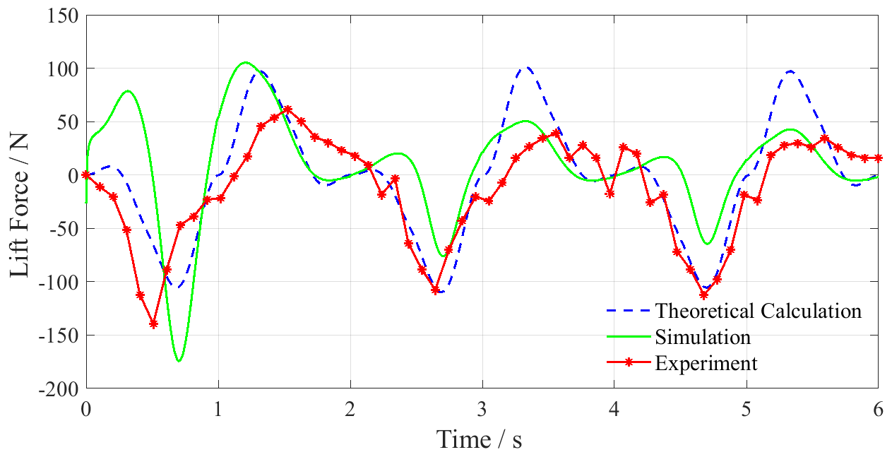
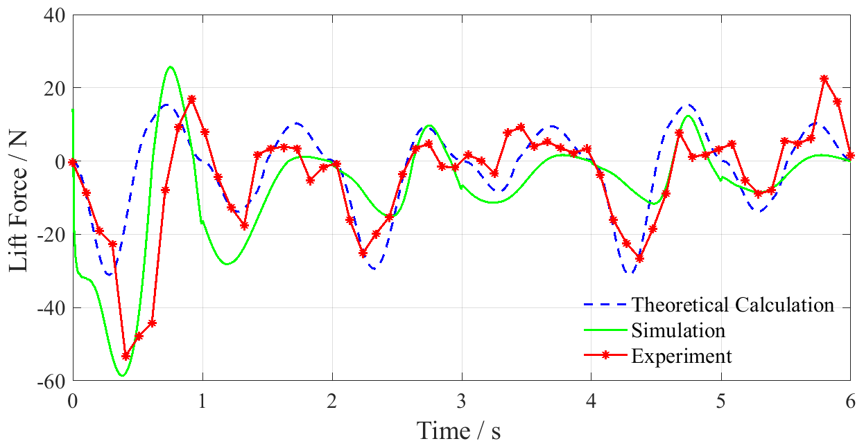
Figures 16 and 18 show the lift curves of swimming with increased and reduced motion trajectory. The maximum positive lift forces of swimming with increased motion trajectory in the theoretical calculation, simulation, and experiment are 98, 108, and 62 N, and the maximum negative lift forces respectively reach −109, −171, and −147 N. The theoretical calculation, simulation, and experimental results of swimming with reduced motion trajectory show that the maximum positive lift forces are 17, 23, and 18 N, and the maximum negative lift forces are −26, −59, and −57 N.
According to the results, the propulsion force of increased amplitude motion trajectory is larger and the propulsion efficiency is higher, but the maximum amplitude of its lift reaches about 207 N, which will greatly reduce the motion stability of the robot. However, the propulsion efficiency of the reduced amplitude motion trajectory is low, which is not suitable for the efficient propulsion of the robot. Based on the above analysis of increased and reduced amplitude motion trajectory and the bionic motion trajectory, it is proved that the bionic motion trajectory has better stability than the increased amplitude motion trajectory and better propulsion efficiency than the reduced amplitude motion trajectory. Therefore, the bionic motion trajectory is more suitable for the hind leg motion planning of the beaver-like underwater robot.
The analysis results of swimming with the bionic, increased, and reduced amplitude motion trajectory show that the rigid–liquid fusion dynamics model can accurately predict the swimming lift, forward force, and force peaks of the hind leg of the beaver-like underwater robot. It proves the correctness of the rigid–liquid fusion dynamics model, and lays the foundation for the subsequent research on the motion and attitude control algorithm of the beaver-like underwater robot.


4.3.3 Flow velocity analysis with hind leg motion in simulation
Figure 19 shows the flow velocity when the hind leg of the beaver-like robot moves in one cycle, where the selected instantaneous has been marked in the diagram. As shown in the figure, the X axis direction is the negative direction of the propulsion force. In the process of 0–0.79 s, the velocity difference between the left side and the right side of the webbed foot gradually increases, and the propulsion force on the hind leg increases accordingly. Subsequently, in the process of 0.79–1.57 s, the flow velocity value on the left side gradually decreased, which was lower than that on the right side, so the propulsion force gradually decreased and turned into a negative value at this stage. In the process of 1.57–2.36 s, the difference value was small, so the propulsion force changed little at this stage. The results in the simulation are consistent with the propulsion force results in Figs. 12, 14, and 16.
In this paper, the swimming force analysis of the hind leg of the beaver-like underwater robot is discussed. The rigid–liquid fusion method is used to fuse the rigid body dynamics of the thighs and calves with the hydrodynamics of the bendable webbed foot. A dynamics model of the robot's hind leg is established, and the forward and lift force acting on the body during swimming of the hind leg are obtained. The hind leg of the beaver-like underwater robot swims with the bionic, increased, and reduced amplitude motion trajectory, respectively. Comparing the forward and lift force generated by the robot's hind leg swimming in the theoretical calculation, Fluent simulation, and experiment, the results are basically the same. This proves the correctness of the rigid–liquid fusion dynamic modeling method proposed for the hind leg swimming of the beaver-like robot. Comparing the theoretical calculation, simulation, and experimental results of the forward and lift force generated by the robot's hind leg swimming under the three motion trajectories, it can be seen that the bionic motion trajectory has higher propulsion efficiency and better motion stability. It verifies the rationality and superiority of the bionic motion trajectory. The proposed dynamic model of hind leg swimming can provide theoretical support for the mechanical analysis of the robot swimming process.
In future work, we will further combine the proposed rigid–liquid fusion dynamics model of the hind leg swimming of the beaver-like robot with the force of the robot body to establish the overall dynamics model of the robot's swimming, and analyze the relationship between the robot's movement posture and hind leg swimming. This will lay the mechanics foundation for the swimming control of the beaver-like underwater robot.
In the future, we will conduct more in-depth hydrodynamics research on the beaver-like robot, and some data used in this paper will be involved. The data sets generated and analyzed during this study are not public, but can be obtained from the corresponding authors upon reasonable request.
GC and DW designed the experiments, and ZW carried them out. GC and DW proposed the model, then ZW developed the model code and performed the simulations. ZW and JT prepared the paper with contributions from all co-authors.
The contact author has declared that none of the authors has any competing interests.
Publisher's note: Copernicus Publications remains neutral with regard to jurisdictional claims in published maps and institutional affiliations.
This research has been supported by National Natural Science Foundation of China (grant nos. 52275037, 51875528, and 41506116), Zhejiang Provincial Natural Science Foundation of China (grant nos. LY20E050018 and LTY21F030001), and Science Foundation of Zhejiang Sci-Tech University (ZSTU) (grant no. 17022183-Y).
This paper was edited by Daniel Condurache and reviewed by two anonymous referees.
Alvarado, P.: Hydrodynamic performance of a soft body under-actuated batoid robot, 2011 IEEE International Conference on Robotics and Biomimetics (ROBIO), IEEE, 1712–1717, https://doi.org/10.1109/ROBIO.2011.6181536, 2011.
Azarsina, F.: Designing a Hydrodynamic Shape and Thrust Mechanism for a Batoid Underwater Robot, Mar. Technol. Soc. J., 50, 45–58, https://doi.org/10.4031/MTSJ.50.5.6, 2016.
Gang, C., Bo, J., and Ying, C.: Accurate and robust body position trajectory tracking of six-legged walking robots with nonsingular terminal sliding mode control method, Appl. Math. Model, 77, 1348–1372, https://doi.org/10.1016/j.apm.2019.09.021, 2020.
Gang, C., Jiajun, T., Xiaocong, T., Zhenyu, W., and Huosheng, H.: Hydrodynamic model of the beaver-like bendable webbed foot and paddling characteristics under different flow velocities, Ocean Eng., 234, 109–179, https://doi.org/10.1016/j.oceaneng.2021.109179, 2021a.
Gang, C., Xin, Y., Xujie, Z., and Huosheng, H.: Water hydraulic soft actuators for underwater autonomous robotic systems, Appl. Ocean Res., 109, 1–12, https://doi.org/10.1016/j.apor.2021.102551, 2021b.
Gang, C., Zhenyu, W., Sheng, Y., Lixin, P., Zhiyang, W., Chidong, Y., and Feihu, X.: Optimal Design of the Shell Structure of a Disk-Shaped Water-Spraying Robot, Mar. Technol. Soc. J., 55, 127–136, https://doi.org/10.4031/MTSJ.55.2.6, 2021c.
Healey, A. J., Rock, S. M., Cody, S., Miles, D., and Brown, J. P.: Toward an improved understanding of thruster dynamics for underwater vehicles, Proceedings of IEEE Symposium on Autonomous Underwater Vehicle Technology (AUV'94), IEEE, 340–352, https://doi.org/10.1109/AUV.1994.518646, 1994.
Jizhuang, F., Wei, Z., Bowen, Y., and Gangfeng, L.: Propulsive efficiency of frog swimming with different feet and swimming patterns, Biol. Open, 6, 503–510, https://doi.org/10.1242/bio.022913, 2017.
Johansson, L. and Norberg, R.: Delta-wing function of webbed feet gives hydrodynamic lift for swimming propulsion in birds, Nature, 424, 65–68, 2003.
Kim, H. J., Jun, B. H., and Lee, J.: Multi-functional bio-inspired leg for underwater robots, 2014 IEEE/RSJ International Conference on Intelligent Robots and Systems, IEEE, 1087–1092, https://doi.org/10.1109/IROS.2014.6942693, 2014.
Moreno Mayz, O., Sanoja, C., and Certad, N.: Design, Modelling, Control and Simulation of Biomimetic Underwater Robot, Latin American Robotics Symposium (LARS), 2019 Brazilian Symposium on Robotics (SBR) and 2019 Workshop on Robotics in Education (WRE), IEEE, 216–221, https://doi.org/10.1109/LARS-SBR-WRE48964.2019.00045, 2019.
Richards, C. T.: The kinematic determinants of anuran swimming performance: an inverse and forward dynamics approach, J. Exp. Biol., 211, 3181–3194, https://doi.org/10.1242/jeb.019844, 2008.
Tiandong, Z., Rui, W., and Shuo, W.: The Design and Control of Squid-Like Underwater Robot, Front. Data Comput., 1, 53–61, https://doi.org/10.11871/jfdc.issn.2096-742X.2019.02.005, 2019.
Wang, G., Wang, K., Ding, L., Gao, H., Yu, H., and Deng, Z.: Analysis of Joint Torque under Single Movement Cycle of Underwater Legged Robot, 2019 IEEE 4th International Conference on Advanced Robotics and Mechatronics (ICARM), IEEE, 773–779, 2019.
Yang, B., Han, L., Li, G., Xu, W., and Hu, B.: A modular amphibious snake-like robot: Design, modeling and simulation, 2015 IEEE International Conference on Robotics and Biomimetics (ROBIO), IEEE, 1924–1929, https://doi.org/10.1109/ROBIO.2015.7419054, 2015.
Zhang, Y., Wang, S., Wang, X. and Geng, Y.: Design and Control of Bionic Manta Ray Robot With Flexible Pectoral Fin, 2018 IEEE 14th International Conference on Control and Automation (ICCA), IEEE, 1034–1039, https://doi.org/10.1109/ICCA.2018.8444283, 2018.
- Abstract
- Introduction
- Kinematics modeling of hind legs of beaver-like underwater robot
- Rigid–liquid fusion swimming dynamics modeling of hind leg of beaver-like underwater robot
- Dynamics verification of hind leg swimming of beaver-like robot
- Conclusions
- Data availability
- Author contributions
- Competing interests
- Disclaimer
- Financial support
- Review statement
- References