the Creative Commons Attribution 4.0 License.
the Creative Commons Attribution 4.0 License.
 | 07 Oct 2022
Spring efficiency assessment and efficient use of spring methods of statically balanced planar serial manipulators with revolute joints only
Chia-Wei Juang
Chi-Shiun Jhuang
Dar-Zen Chen
This paper proposes a spring efficiency assessment of a statically spring-balanced planar serial manipulator. The admissible spring configurations for the static balancing of planar serial manipulators without auxiliary links have been determined in the past. Gravity is balanced by the spring configuration systematically; however, the spring configuration also contains counter-effects between springs. Conceptually, with fewer counter-effects between springs, there is less burden on the spring system, which means that the springs are used more efficiently, and accordingly, the system would be safer, and its service life would be longer. In this study, the spring energy is represented in a quadratic form. The coefficients in a quadratic form represent the change in elastic energy with the relative position between links, which is named “elastic pseudo-stiffness”. Compared to the quadratic form of gravity energy, those elastic pseudo-stiffnesses for static balancing are regarded as positive contributions of a spring, while those that contain counter-effects are seen as negative ones. Spring efficiency is defined as the ratio of the elastic pseudo-stiffnesses, which has positive contributions for balancing to total elastic pseudo-stiffnesses. To use springs efficiently, the counter-effects, which are functions of spring parameters, need to be decreased, including spring stiffness and the attachment location of springs on links. A method to use spring efficiently by adjusting spring parameters is developed. Furthermore, it is found that, for a spring attached between adjacent links, the spring efficiency is 100 %, and the spring efficiency decreases while the number of joints over which the spring spans increases. In a spring manipulator system, the efficiency is negatively correlated to the payload. As an example, an efficiency assessment on a 3 degrees of freedom (DOF) manipulator is shown at the end.
- Article
(6910 KB) - Full-text XML
- BibTeX
- EndNote


In recent decades, new static balancing technologies and system designs have been developed for multiple applications, such as a wearable exoskeleton for rehabilitation and training (Arakelian and Ghazaryan, 2008; Lin et al., 2013; Tschiersky et al., 2019; Kuo et al., 2021) and robotic manipulators (Arakelian, 2016; Kim and Cho, 2017). These manipulators provide a better control of the performance and more efficiency because the actuating force that is sustaining the weight of their system is partially or fully balanced.
One of the spring balancing methods uses a serially connected, four-bar, parallelogram mechanism; this mechanism uses auxiliary links to connect other links vertically to the ground, forming a pseudo-base, and each parallelogram is independently balanced by a single spring (Nathan, 1985; Rahman et al., 1995; Lin et al., 2010). Another kind of spring balancing method uses auxiliary links to form a pantograph mechanism that is located in the center of mass. Springs are then attached to the center of mass to keep the total energy constant (Agrawal and Fattah, 2004a, b; Fattah and Agrawal, 2006; Najafi and Sepehri, 2011). Besides the methods with auxiliary links, Jamshidifar et al. (2021) proposed an approach by using gravity compensator consisting of one spring and multiple pulleys, which mitigates the issue of workspace interference caused by auxiliary linkages. In addition to the perfect balance, several methods with the partial balancing of a robot are proposed. For instance, adding gear spring modules as gravity compensators on the three revolute–prismatic–spherical (3 RPS) parallel robot (Nguyen et al., 2020) can balance the gravity partially. However, applications with auxiliary links or additional devices have several disadvantages, such as motion interference caused by the auxiliary links. Also, the additional mass of additional devices may increase the load of springs. To mitigate these problems, balancing methods that do not use auxiliary links but directly attach the springs to the manipulator have been proposed (Lin et al., 2011; Deepak and Ananthasuresh, 2012; Lee and Chen, 2014; Juang and Chen, 2022) and used in this paper. The gravity balancing method without auxiliary links uses springs to balance the gravity of manipulators systematically. Ideally, the elasticity of all of the springs is used to cancel out the gravity, but the method, as the manipulator's degrees of freedom (DOF) are more than 2, requires multiple springs to be installed and therefore contains counter-effects between springs. In other words, only part of the elasticity is used to counter the gravity of manipulators; the other parts are redundant and cancel each other out. For example, for a 2 DOF manipulator in Fig. 1, referring to Lee and Chen (2014), two springs S1,3 and S2,3 are installed, where S1,3 is the spring attached between the first link (ground link) and the third link, which contributes elasticity to balance the gravity of the manipulator, and also remains the redundant elasticity that is balanced by S2,3 (the spring attached between the second link and the third link), so that a counter-effect exists between S1,3 and S2,3.


Conceptually, the fewer the counter-effects between springs, the more the burden of the spring system is decreased. This means that the springs are more efficiently used; hence, the system would be safer, and its service life would be extended. The gravity balancing method by springs without auxiliary links is developed (Lin et al., 2011; Deepak and Ananthasuresh, 2012; Lee and Chen, 2014; Juang and Chen, 2022), but there are no research papers discussing the issue of how to use springs efficiently to balance the gravity of a manipulator. This study aims to develop a method to use springs efficiently, and thereby, the assessment of the spring efficiency is presented here.
The paper is structured as follows. Section 2 discusses the gravitational and elastic energies of a spring manipulator system and the static balancing conditions. Section 3 presents the concept of spring efficiency and the criteria for the efficient use of a spring. Furthermore, Sect. 4 discusses the efficiency assessment of a spring manipulator system, and the efficient spring configurations are proposed. In addition, the characteristics of spring parameters and the effect of payload on the system spring efficiency are suggested. Section 5 discusses the efficiency assessment by presenting an illustrative example of a spring-balanced, 3 DOF planar manipulator. The adjustment of spring parameters and payload are also displayed. Section 6 serves as a conclusion of all the previous sections.
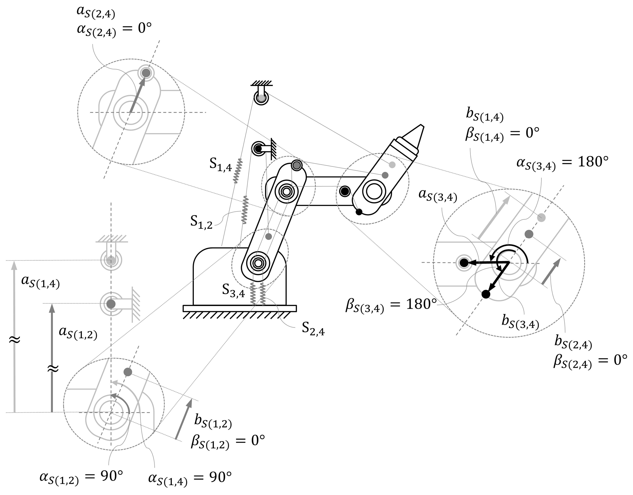
Figure 4Schematic of the installation of the springs and the attachment parameters of a 3 DOF manipulator with a spring configuration Λ1.
2.1 Gravitational pseudo-stiffness
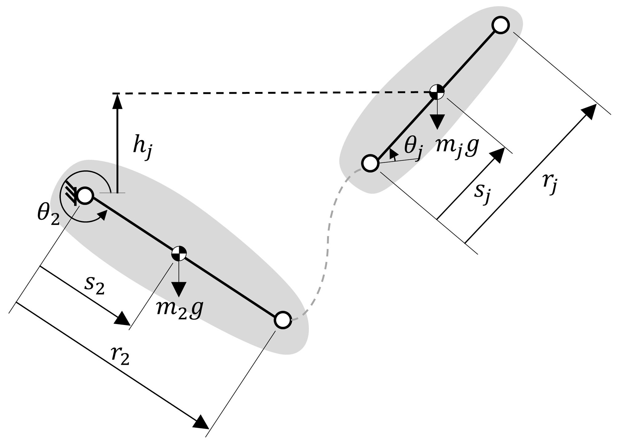
For a serial planar manipulator with revolute joints only, we assume that the center of mass (COM) of each link is located on the axis between link pivots. In Fig. 2, the symbols used to represent a link's dimensions in the manipulator system are presented. While rj is the length of link j, sj is the distance between a joint and the center of mass for link j. mj is the mass of link j, and g is the gravitational acceleration. θj is the relative angle between link j and the previous link j−1, and hj is the height of link j from the ground.
For link j, gravitational energy is expressed as follows:
The height of link j is expressed as follows:
where Θu,v represents the angle between link u and link v, which is expressed as follows:
The gravitational energy of the manipulator system can be expressed as follows:
which can be rewritten in the following quadratic form:
where
The term G1,u can be viewed as a pseudo-stiffness between the ground link and link u caused by gravity. G1,u is named as gravitational pseudo-stiffness. In the following, we set
where |G1,u| is regarded as a parameter that is always positive since the mass and the length of the manipulator are positive. Therefore, according to Eq. (6), the sign of the gravitational pseudo-stiffnesses depends on the angle in the cosine term. Note that, in Eqs. (5)–(7), r1 is the reference length of the ground link, the magnitude is self-defined, and the unit is in meters (m). Here r1 is set as 1 (m) and is used to normalize the distances refer to the coordinate system on the ground.
2.2 Elastic pseudo-stiffness
Figure 3 illustrates a zero-free length (ZFL) spring Si,j that is installed between link i and link j. The ZFL spring denotes that the spring has zero length in the unstretched condition, and the length of spring equals the spring's elongation. In Fig. 3, ri and rj indicate the lengths of links i and j, lS(i,j) is the spring elongation of spring Si,j, aS(i,j) is the attachment distance of Si,j on the proximal link i, bS(i,j) is the attachment distance of Si,j on the distal link j, αS(i,j) is the attachment angle of Si,j on proximal link i, and βS(i,j) is the attachment angle of Si,j on distal link j.
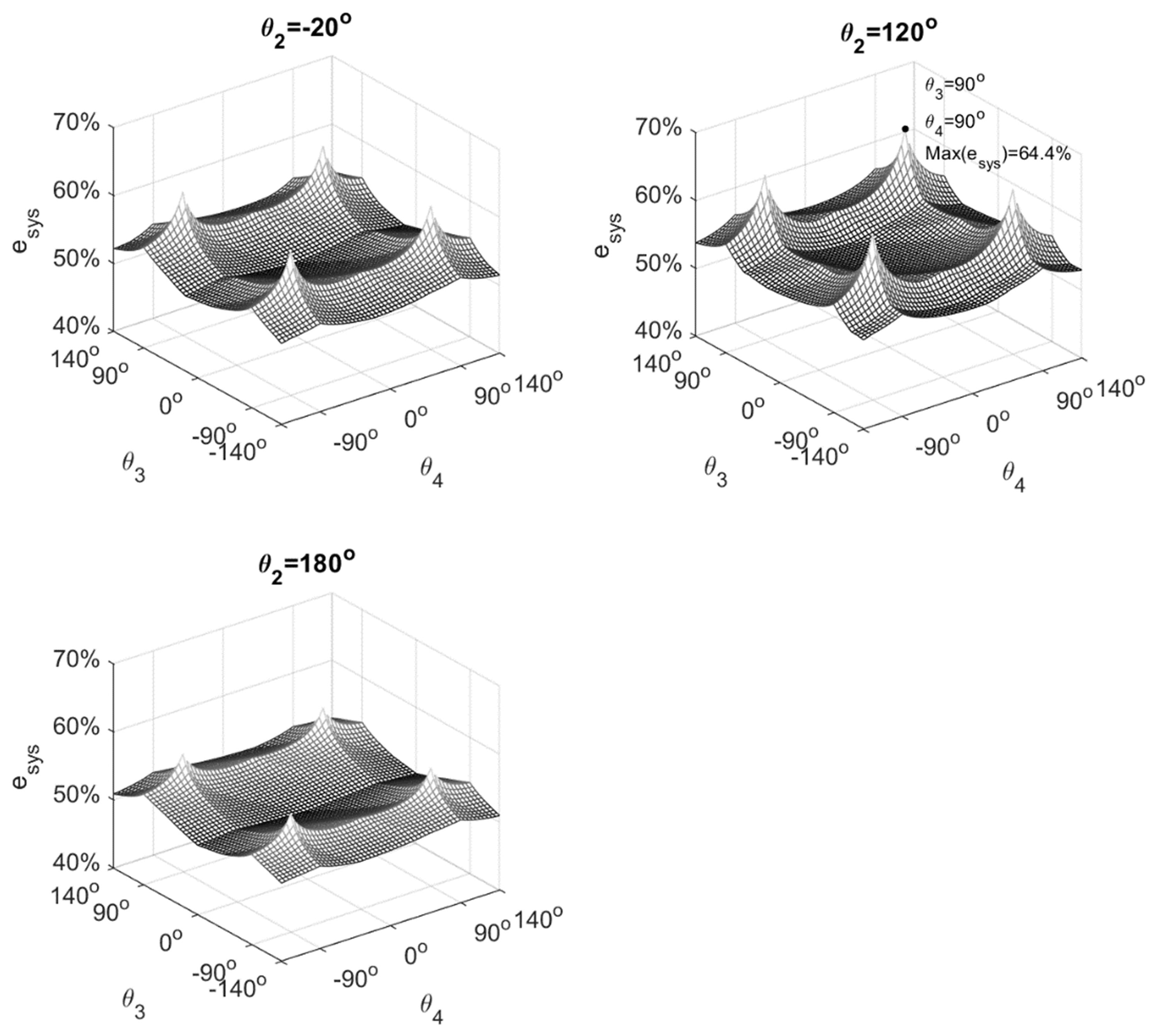

Figure 6The potential energies of the example 3 DOF spring manipulator system in the workspace.
As a ZFL spring is attached between links i and j, the elongation is expressed as follows:
and the elastic energy of Si,j, with spring stiffness ki,j, is expressed as follows:
By substituting Eq. (8) into Eq. (9), US(i,j) can be expressed as follows:
where
in which AS(i,j) and BS(i,j) represent the ratio of spring attachment distance to the link length, i.e.,
and
Equations (11a)–(11d) can be regarded as pseudo-stiffnesses between two links, for example, is the pseudo-stiffness between link u and link v caused by the elasticity of spring Si,j. Thus, is named as an elastic pseudo-stiffness.
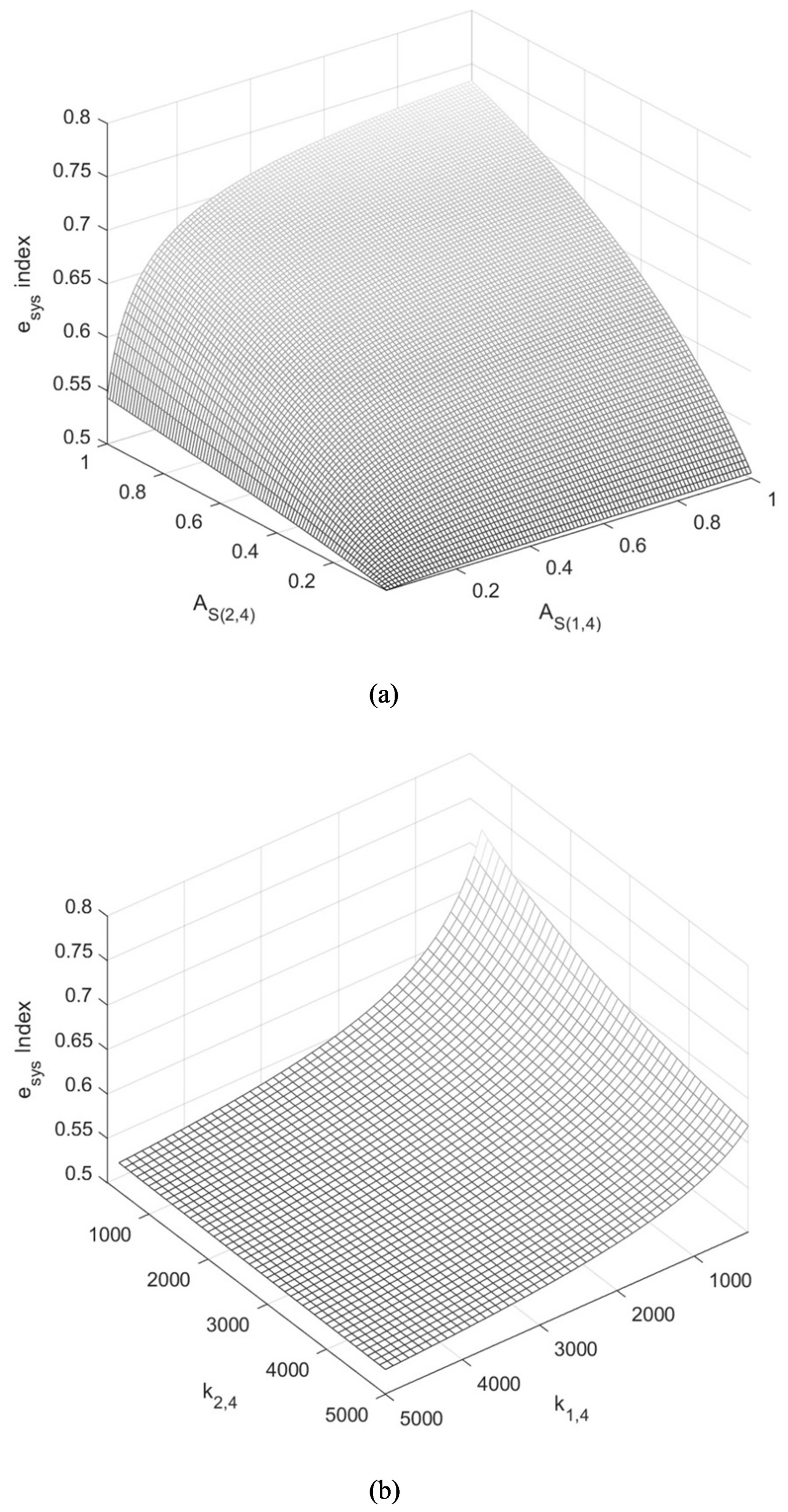
Figure 7(a) The trend of the system spring efficiency index of the example 3 DOF manipulator and the attachment distances of the springs (AS(1,4) and AS(2,4)). (b) The trend of the system of the spring efficiency index for the example 3 DOF manipulator and spring stiffnesses (kS(1,4) and kS(2,4)).
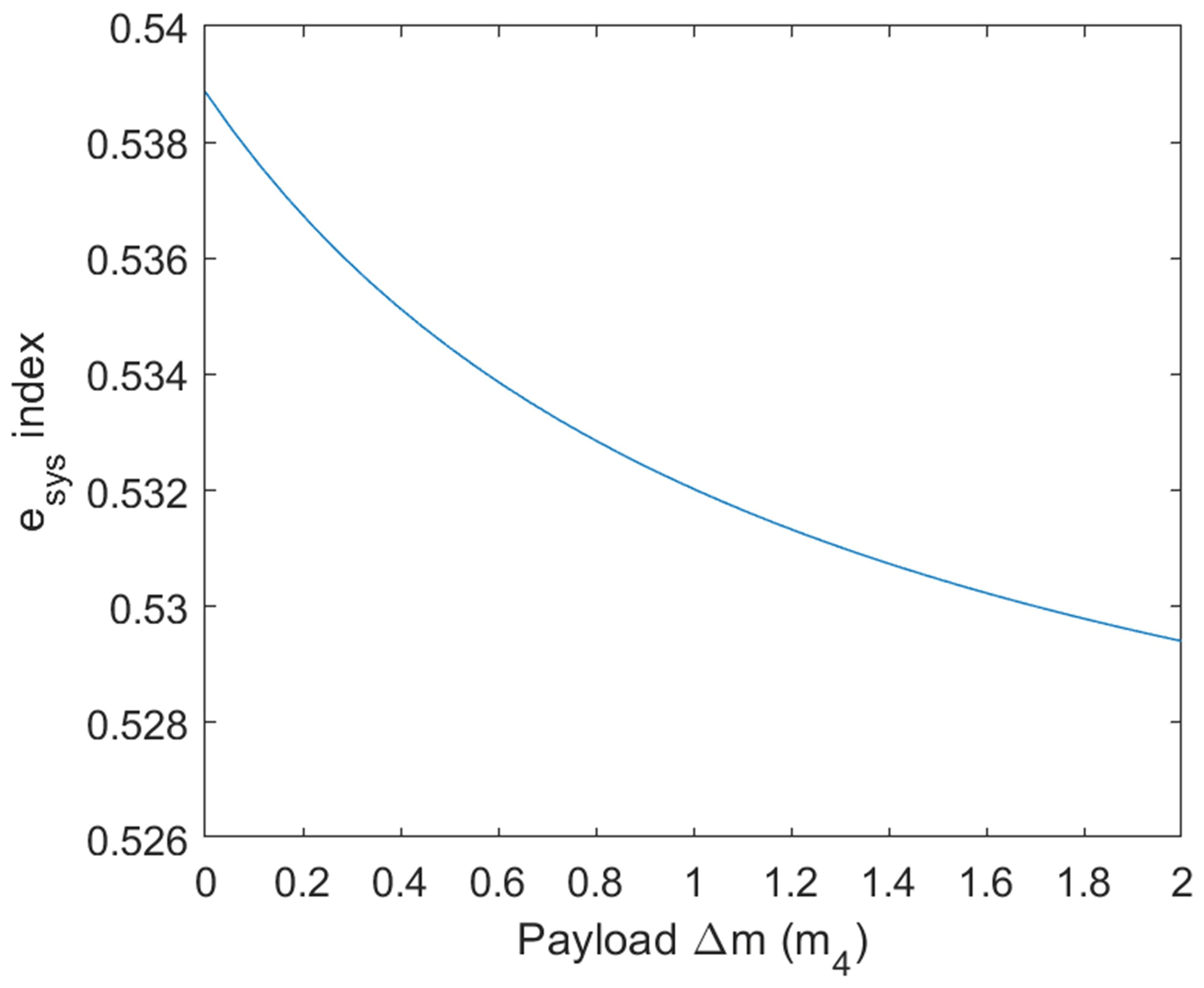
Figure 8The trend of the system spring efficiency index of a 3 DOF manipulator and variable payload.
According to Eqs. (11a)–(11d), the elastic pseudo-stiffnesses provided by a spring Si,j existed between all links between link i and link j.
A spring attached between two adjacent links, where only one joint is spanned over, is named a “mono-articulated spring”. Otherwise, a spring attached between a pair of links that are not adjacent, where multiple joints are spanned over, is named a “multi-articulated spring”. The number of joints a spring spans over determines the number of elastic pseudo-stiffnesses provided by a spring. For a mono-articulated spring , the elastic energy Eq. (10) can be simplified as follows:
It is found that a mono-articulated spring provides only one elastic pseudo-stiffness that exists between link i and link i+1, as shown in Eq. (11a), as follows:
And for a multi-articulated spring that spans over two joints, , there are three elastic pseudo-stiffnesses, including the elastic pseudo-stiffness that exists between link i and link i+2, as shown in Eq. (11a), as follows:
The elastic pseudo-stiffness exists between link i and link i+1, according to Eq. (11b), as follows:
And the elastic pseudo-stiffness exists between link i+1 and link i+2, according to Eq. (11c), as follows:
Generally, the number of elastic pseudo-stiffnesses of Si,j is , and according to the link number, the general formulas of elastic pseudo-stiffnesses are Eqs. (11a)–(11d).
In this paper, only the extension spring is used, i.e., the spring stiffness kS(i,j) is positive, and since aS(i,j) and bS(i,j) are the attachment distance of a spring which must be positive, AS(i,j) and BS(i,j) are therefore positive. It is shown that the sign of the elastic pseudo-stiffnesses of the spring, i.e., Eqs. (11a)–(11d), depends on the angles in the cosine term.
The term, , in Eq. (10) is a constant which does not vary with the posture of the manipulator, and the other terms depend on the postures of the manipulator.
2.3 Gravitational and elastic energies balancing condition
The static balancing of a spring manipulator system is achieved when the total energy of the system is a constant in different postures of the manipulator. Comparing Eq. (5) with Eq. (10), the summation of the terms, which vary with the posture of the manipulator, should be zero when static balancing is achieved. Therefore, the static balancing of a spring manipulator can be simplified as the summation of the pseudo-stiffnesses between the links of the spring manipulator system as being zero.
Since the gravitational pseudo-stiffnesses only exist between the ground and other links, the condition of gravitational energy balancing is that the summation of pseudo-stiffnesses between the ground and other links is zero, which can be expressed as follows:
According to Eqs. (11a)–(11d), the spring contributes the elastic pseudo-stiffnesses between the ground and others which can be used to balance the gravitational pseudo-stiffnesses, while the spring still contains elastic pseudo-stiffnesses between non-ground links. That is, such remaining elastic pseudo-stiffnesses need to be balanced by the elastic pseudo-stiffnesses contributed by other springs (i.e., the counter-effect between springs). The elastic energy balancing condition is as follows:
When both conditions in Eqs. (16a) and (16b) are achieved, then gravity balancing is achieved.
It is shown that, besides the elastic pseudo-stiffnesses used to balance the gravitational pseudo-stiffnesses, i.e., Eq. (16a), there are counter-effects between springs, i.e., Eq. (16b). The counter-effects between springs consist of the remaining elastic pseudo-stiffnesses which need to be balanced (elastic balanced part), and the corresponding elastic pseudo-stiffnesses contributed by other springs is used to cancel out the elastic balanced part (elastic balancing part). The elastic pseudo-stiffnesses of a spring can therefore be separated into the “balancing part” and “balanced part”. To identify whether an elastic pseudo-stiffness is the balancing or the balanced part, more explanations are given in the following section.
3.1 Spring efficiency
The elastic pseudo-stiffness contributed by a spring can be classified into two groups, i.e., the balancing part and the balanced part. Accordingly, the spring efficiency is conceptually defined as ratio of the balancing part to total elastic pseudo-stiffnesses. The efficiency of a spring Si,j is expressed as follows:
According to Eq. (17), to enhance the spring efficiency of a spring, the balancing part should be increased. On the other hand, the balanced part should also be decreased. The criteria for the efficient use of springs are discussed in the following section.
3.2 Criteria for efficient use of a spring
To achieve the gravitational balancing condition in Eq. (16a), the sign of the elastic pseudo-stiffness must be opposite to the sign of the corresponding gravitational pseudo-stiffness. Under this circumstance, such elastic pseudo-stiffness is regarded as the balancing part; otherwise, it is regarded as the balanced part.
In a previous study (Juang and Chen, 2022), the admissible attachment angles of springs for statically balanced planar articulated manipulators have been proposed. For a ground-connected spring S1,v, to ensure that S1,v is efficiently used to balance the gravity rather than having negative effects on balancing, all the elastic pseudo-stiffnesses for are required to be shown as the opposite sign of the corresponding gravitational pseudo-stiffness G1,j. Referring to Juang and Chen (2022), the ground-connected springs should be attached with .
A criterion for using a ground-connected spring efficiently is proposed as C1, which is defined below.
-
C1 will ensure that a ground-connected spring is efficiently used to balance the gravity, so the ground-connected spring should be attached with .
-
For such a ground-connected spring to satisfy C1, the elastic pseudo-stiffnesses are the balancing part. However, the ground-connected spring not only contributes the balancing elastic pseudo-stiffnesses which are used to offset gravitational pseudo-stiffnesses but also leaves the elastic pseudo-stiffnesses which need to be balanced. The elastic pseudo-stiffnesses for i>1 are left as the balanced part. Therefore, non-ground-connected springs need to be installed.
-
To ensure that a non-ground connected spring Sp,q is efficiently used to balance the elasticity, rather than having negative effects on balancing, the elastic pseudo-stiffnesses contributed by the non-ground-connected spring should be used to compensate for the corresponding elastic-stiffnesses left by the ground-connected springs. Referring to Juang and Chen (2022), the ground-connected springs should be attached with or . For the non-ground connected spring attached with , the elastic pseudo-stiffnesses are contributed as the balancing part, and the elastic pseudo-stiffnesses for i>p are left as the balanced part. For the non-ground connected spring attached with , the elastic pseudo-stiffnesses are contributed as the balancing part, and the elastic pseudo-stiffnesses for j<q are left as the balanced part.
A criterion for using non-ground-connected spring efficiently is proposed as C2 below.
-
C2 will ensure that a non-ground-connected spring is efficiently used to balance the elasticity, so the non-ground-connected spring should be attached with or .
-
In a spring manipulator system, if there are balanced elastic pseudo-stiffnesses that do not correspond to any balancing elastic pseudo-stiffness, then the additional spring needs to be installed. Not until all the balanced elastic pseudo-stiffnesses are offset can the elastic energy balancing condition in Eq. (16b) can be achieved.
3.3 Attachment of spring and spring efficiency
For a multi-articulated spring Si,j for , according to Eq. (17), the spring efficiency of Si,j can be expressed as follows:
where x is the magnitude of balancing elastic pseudo-stiffnesses contributed by spring Si,j, and y is the magnitude of the balanced elastic pseudo-stiffnesses remained by spring Si,j. According to the criteria for C1 and C2, for the efficient use of a spring, there are three types of springs, namely the ground-connected spring with and the non-ground-connected spring with and , while x and y are different among the spring types.
For a ground-connected spring S1,j with , the magnitude of balancing elastic pseudo-stiffnesses contributed by S1,j is as follows:
And the magnitude of the balanced elastic pseudo-stiffnesses left by S1,j is as follows:
According to Eqs. (18), (19a), and (19b), it is shown that the spring attachment parameters, AS(1,j) and BS(1,j), determine the magnitude of spring efficiency. While the larger AS(1,j) have the larger x, and y is unchanged, the condition leads to a better eS(1,j), and while the larger BS(1,j) have the larger x and y, the result leads to a worse eS(1,j).
For a non-ground-connected spring Si,j with , the magnitude of the balancing part contributed by spring Si,j is as follows:
And the magnitude of the balanced part that left by spring Si,j is as follows:
According to Eqs. (18), (20a), and (20b), it is found the larger values of AS(i,j) have the larger x, and y is unchanged. The condition leads to a better eS(i,j) and with a larger BS(i,j), which have the larger x and y leading to a worse eS(i,j).
For a non-ground-connected spring Si,j with , the magnitude of the balancing part contributed by the spring Si,j is as follows:
And the magnitude of the balanced part remained by spring Si,j is as follows:
According to Eqs. (18), (21a), and (21b), it is found that, where the larger value of BS(i,j) have the larger x, and y is unchanged, it leads to a better eS(i,j). Where the larger AS(i,j) have the larger x and y, it leads to a worse eS(i,j).
Note that, for a mono-articulated spring , according to Eq. (14), it is found that only one balancing elastic pseudo-stiffness is contributed. Therefore, for a mono-articulated spring, , y=0, so the efficiency must be 100 %.
According to Eqs. (18) and (19), it is known that the mono-articulated must have better efficiency than a multi-articulated spring. As the number of joints that the spring spans over increases, the number of balancing and balanced elastic pseudo-stiffnesses are both increased, and the spring efficiency is changed as follows:
The Δx and Δy are the additional terms to the balancing and balanced part, respectively, for the same spring under the same condition, while the number of joints the spring spans over increases. According to Eq. (23), it is shown that the additional terms in the denominator are larger than those in the numerator; therefore, , the spring efficiency, decreases as the number of joints the spring spans over increases.
In this section, how the spring attachment parameters affect the spring efficiency is examined. Also, it is shown that, as the spring is installed under the same condition, the lower the number of joints the spring spans over, the better the spring efficiency. However, to achieve the static balancing of the spring manipulator system, the spring attachment parameter and the number of joints the spring spans over are not arbitrary. In the following section, the constraints of the spring attachment parameter and the assessment of system spring efficiency are discussed. Note that, referring to Juang and Chen (2022), the non-ground-connected springs can also be attached with , which is not considered in this paper. Since the number of joints that the springs span over in the configuration with such a spring is more than the configurations with only and springs, the spring efficiency is worse if spring is used, according to the conclusion above. Hence, the non-ground-connected spring with is not considered in this paper.
4.1 System spring efficiency and efficient spring configurations
The efficiency of a spring manipulator system can be conceptually defined, as follows, to show the performance of efficiency in the system.
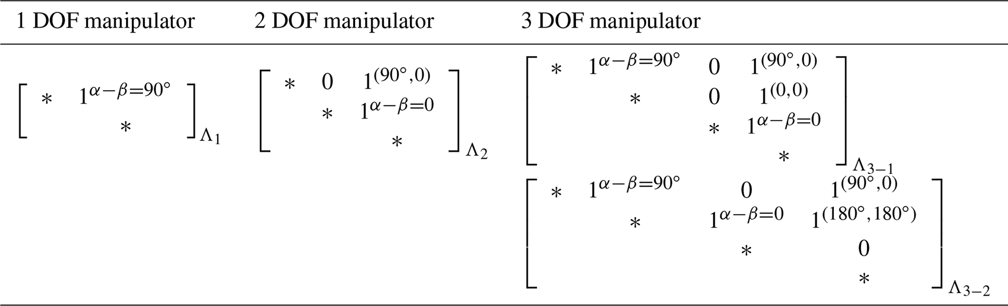
It is known that the lower the number of joints that the springs span over, the better the performance on spring efficiency. Therefore, the spring configuration with a lower total number of joints that springs span over conceptually has a better system spring efficiency. According to Juang and Chen (2022), the admissible spring configurations have been proposed in which the configurations with the minimum total number of joints which springs span over for a 1–3 DOF manipulators are listed in Table 1, which can be regarded as efficient spring configurations.
Table 1The efficient spring configurations for the 1–3 DOF manipulators.
In the system, the spring attachment parameters are constrained by the balancing equations as in, i.e., Eqs. (16a) and (16b), so the spring parameters are not arbitrarily used. According to Eqs. (16a) and (16b), to attain static balancing, the magnitude of the balancing elastic pseudo-stiffnesses should be equal to the corresponding magnitude of the balanced gravitational elastic pseudo-stiffnesses. We set the summation of the magnitude of the balanced gravitational pseudo-stiffnesses as X and the summation of the magnitude of the balanced elastic pseudo-stiffnesses as Y. The balancing part of all the springs in the system should be equal to the summation of the balanced gravitational pseudo-stiffnesses and the balanced elastic pseudo-stiffnesses, i.e., X+Y, and the total elastic pseudo-stiffnesses (balanced elastic pseudo-stiffnesses + balancing elastic pseudo-stiffnesses) of all the springs are equal to X+2Y. The system spring efficiency in Eq. (24) can be rewritten as follows:
where X is given by the length/mass of the manipulator. Therefore, the magnitude of balanced elastic pseudo-stiffnesses, which is composed of Y, determines the performance of system spring efficiency. To determine the magnitude of the balanced elastic pseudo-stiffnesses in a system, the constraints of spring parameters should be discussed.
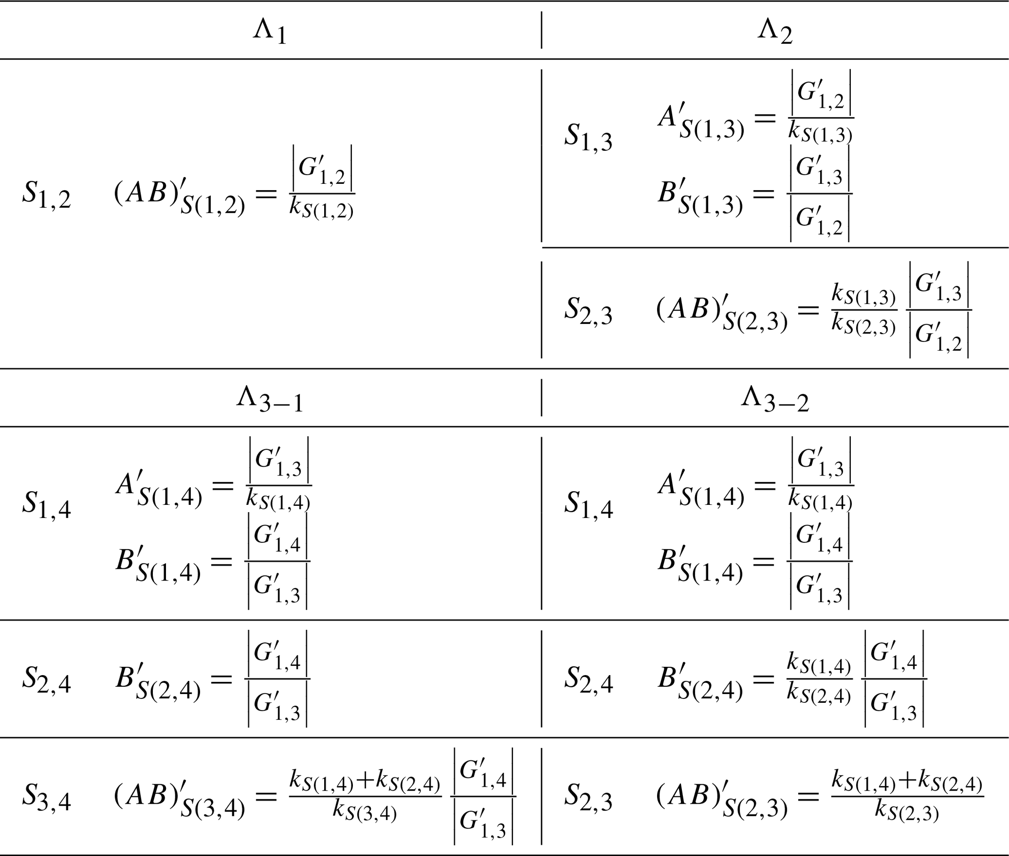
Table 2Adjustment of the spring attachments for efficient spring configurations.
4.2 Spring parameter determination and system spring efficiency
The spring parameters can be determined by the balancing Eqs. (16a) and (16b). We take an efficient spring configuration for a 3 DOF manipulator Λ3−1 as an example. The balanced gravitational pseudo-stiffnesses are G1,2, G1,3 and G1,4. According to C1, S1,4 is attached with , which leaves the balanced elastic pseudo-stiffnesses , , and . According to C2, S2,4 is attached with , and the balanced elastic pseudo-stiffness is left. S1,2 and S3,4 are mono-articulated springs which have no balanced elastic pseudo-stiffness. According to Eqs. (16a) and (16b), the balancing equations are listed as follows:
According to Eqs. (26a), (26b), (26d), and (26e), the constraints of spring parameters are found in the following:
The balanced gravitational pseudo-stiffnesses are as follows:
According to Eqs. (27a)–(27d), the balanced elastic pseudo-stiffnesses can therefore be rewritten as follows:
That is, for Λ3−1,
It is shown that, for a 3 DOF manipulator installed with spring configuration Λ1, where the workspace, dimension, and the mass of the links are given, X would be a constant. Conceptually, the larger AS(1,4) and AS(2,4) bring the smaller value of Y, leading to a better system spring efficiency. Therefore, considering the reasonable spring attachment distance, it is suggested to choose the allowed maximum AS(1,4) and AS(2,4) for a better system spring efficiency.
On the other hand, according to Eqs. (27b) and (27d), the constraints indicate that the spring stiffness kS(1,4) is inversely proportional to AS(1,4), and kS(2,4) is inversely proportional to AS(1,4) and AS(2,4). Therefore, considering the reasonable spring stiffness, it is suggested to choose the minimum kS(1,4) and kS(2,4) for a better system spring efficiency.
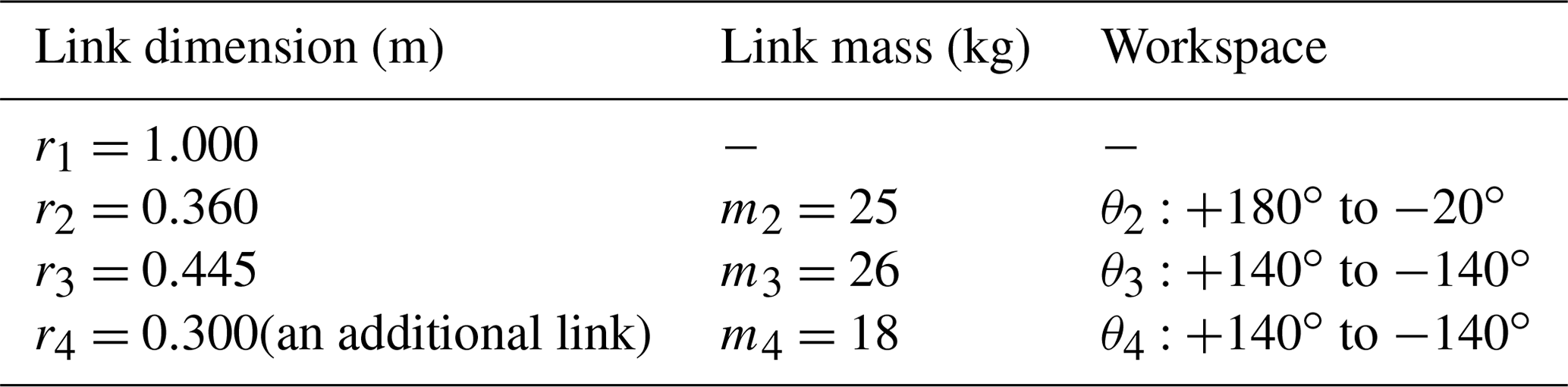
Table 3The dimension, mass, and workspace for the links of an example 3 DOF planar manipulator.
Similarly, for a 2 DOF manipulator with the spring configuration Λ2, the spring S1,3 is attached with , so that the balanced pseudo-stiffness is left. S2,3 is a mono-articulated spring; therefore, no balanced pseudo-stiffness is left. For a 3 DOF manipulator with a spring configuration Λ3−2, the spring S1,4 is attached with , so the balanced pseudo-stiffnesses , and are left. S2,4 is attached with , so the balanced pseudo-stiffness is left. S1,2 and S2,3 are mono-articulated springs. According to the balancing equations (i.e., Eqs. 16a and 16b), the constraints of the spring parameters and the factors to determine the esys can be found. The methods for the efficient use of springs in the configurations are developed as follows.
-
R1 is used for a better esys using a 2 DOF manipulator with the spring configuration Λ2, where the spring S1,3 is suggested to be attached with a larger AS(1,3) and a smaller kS(1,3).
-
R2 is used for a better esys using a 3 DOF manipulator with the spring configuration Λ3−1, where S1,4 is suggested to be attached with a larger AS(1,4) and a smaller kS(1,4). S2,4 is suggested to be attached with a larger AS(2,4) and a smaller kS(2,4).
-
R3 is used for a better esys using a 3 DOF manipulator with the spring configuration Λ3−2, where S1,4 is suggested to be attached with a larger AS(1,4) and a smaller kS(1,4). S2,4 is suggested to be attached with a larger BS(2,4) and a smaller kS(2,4).
For a 1 DOF manipulator, only one mono-articulated spring S1,2 with is attached; therefore, the system spring efficiency of the 1 DOF manipulator is equal to the spring efficiency of S1,2, which always achieves 100 %.
Note that, for the method using auxiliary links which are vertical to the ground and form a pseudo-base (Lin et al., 2010), each link of the manipulator is independently balanced by a spring. Based on that method, the balancing of each link can be regarded as the balancing of the 1 DOF manipulator in our method. Therefore, the spring efficiency can be seen as being 100 %.
Table 5System efficiency index after adjustment of spring parameters.
Note that, according to the constraints of spring parameters in Eqs. (27b), (27d), and (27e), the spring stiffnesses are changed with adjustment of spring attachment points.
4.3 Payload and system spring efficiency
In the previous section, the dimensions and mass of the links are given; therefore, |G1,j| is considered to be a constant. To go further, in this section, the effect of adding payload on system spring efficiency is discussed.
For a given manipulator, when a payload Δm is added at the COM of the end link, are changed, as follows:
According to Eqs. (30a) and (30b), it is found that, when a payload is added, both X and Y are increased, i.e., the system spring efficiency is changed as follows:
where ΔX is the additional term of X in which a payload Δm is added at the COM of the end link, and ΔY is the additional term of Y where a payload Δm is added at the COM of the end link. According to Eq. (33), the amount of change in the denominator is greater than that in the numerator; therefore, .
As the payload changed, the attachment of springs is adjusted accordingly. Assuming that the spring stiffnesses are fixed, only the attachment distances of the springs AS(i,j) or BS(i,j) are adjustable. According to Eqs. (27a)–(27e) and (32), as a payload, Δm is added at the COM of the fourth link, and the required adjustment of the attachment distances of the springs Λ3−1 can be determined. It is found that the springs S1,4, S2,4, and S3,4 are adjusted, and S1,2 remained unchanged. Similarly, the adjustment of springs as a payload added at the COM of the end link for the efficient spring configurations (Table 1) can be found by the balancing equations. The results are listed in Table 2.
The ABB IRB 140 robot arm (ABB Inc., Auburn Hills, MI 48326, USA), an industrial manipulator with six rotational axes, was used in the real world (Suárez and Heredia, 2013; Almaged, 2017). The example referring to the dimension, mass, and workspace of the links of the ABB IRB 140 industrial manipulator is proposed. The operation of the manipulator is assumed to work at a constant speed. Only a planar motion is considered, and an additional link is added to form a 3 DOF planar manipulator. The dimension, mass, and workspace are listed in Table 3.
After substituting the dimension and mass of the links into Eq. (7), |G1,2| becomes 553.7, |G1,3| becomes 303.8, and |G1,4| becomes 88.2.
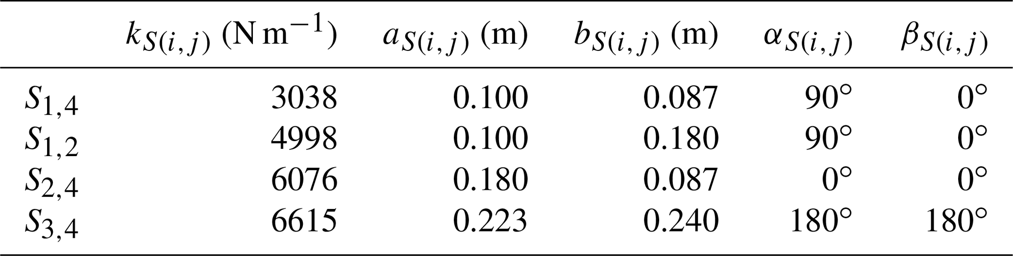
In the example, the spring configuration Λ3−1 is used. The spring design parameters of the example 3 DOF manipulator are listed in Table 4.
The schematic of the manipulator and spring attachment parameters are presented in Fig. 4 (note that, in Fig. 4, the springs attached to a manipulator are ZFL springs that can be formed by adopting a cable pulley arrangement; Ou and Chen, 2017).
Substituting the spring parameters in Table 4 and |G1,2|, |G1,3| and |G1,4| into Eqs. (30a) and (30b), it is found that X and Y are variables which are determined by the posture of the links (i.e., θ2, θ3 and θ4). Hence, according to Eq. (25), the system spring efficiency is also a variable. The system spring efficiency in the workspace is shown in Fig. 5 (note that, to present the figure clearly, several θ2 angles are used to represent the system spring efficiency of workspace).
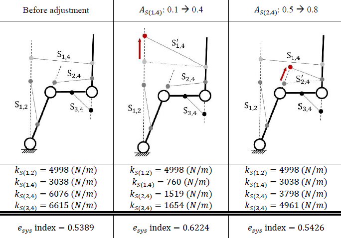
The system spring efficiency is a variable which is determined by the posture of the links. Therefore, the “system spring efficiency index” is proposed, which is defined as the mean of esys in the workspace. The index can fairly represent the efficiency of springs in a spring manipulator system. For the case in Fig. 5, the system efficiency index is 0.5389.
To show the quality of static balancing, the gravitational and elastic energies in the workspace are presented in Fig. 6.
According to R2, the spring parameters can be adjusted to achieve a better esys. As AS(1,4) is adjusted to 0.4, kS(1,4) is changed to 760 (N m−1), and the spring S2,4 remains at the same attachment points, so the system efficiency index would increase to 0.6224. As AS(2,4) is adjusted to 0.8, kS(2,4) is changed to 3798 (N m−1), and the spring S1,4 remains at the same attachment points, so the system efficiency index would slightly increase to 0.5426. Table 5 shows the improvement in the system efficiency index after adjustment.
The system efficiency index variance over AS(1,4) and AS(2,4), from 0–1, is shown in Fig. 7a. One varied over kS(1,4), and kS(2,4) is presented in Fig. 7b.
When a payload Δm is added to the center of mass of the end link, the trend of the spring efficiency index with the increasing of payload Δm is shown in Fig. 8.
Note that the unit of the payload Δm is the ratio of Δm to the mass of the end link m4. In Fig. 8, it is shown that, although in this example there is a slight effect of payload on the spring system efficiency index, the trend still shows that, when the payload increases, the spring system efficiency index decreases.
This paper proposes a method to assess the spring efficiency and other methods for the efficient use of springs. The definition of pseudo-stiffness is provided, which can be regarded as the effect of the relative position between two links on potential energy. Static balancing condition can be simplified as the summation of pseudo-stiffnesses being zero. The elastic pseudo-stiffnesses of springs are classified into two categories, namely the balancing part and the balanced part. In this paper, spring efficiency is defined as the ratio of balancing part to total elastic pseudo-stiffnesses. Conceptually, for the efficient use of a spring, it requires an increase in the balancing part. Following this concept, the criteria for the efficient use of springs are proposed, where the pseudo-stiffnesses contributed by ground-connected springs should be used to compensate the gravitational pseudo-stiffnesses, and the pseudo-stiffnesses contributed by non-ground-connected springs should be used to compensate the elastic pseudo-stiffness retained by ground-connected springs. Also, a method to use a spring efficiently by adjusting the spring attachment points on the links and spring stiffness is developed. Furthermore, it is found that, as the number of joints that the spring spans over increases, so the spring efficiency decreases. By extending the result of the efficient use of a spring to the spring manipulator system, it is shown that spring configurations with the minimum number of joints that a spring spans over can be regarded as efficient spring configurations. Furthermore, considering that a payload is added at the COM of the end link, it is found that the system spring efficiency is negatively correlated to the amount of payload. Finally, a 3 DOF manipulator system spring efficiency assessment is shown as an illustrative example.
The code in this research is available upon request by contact with the corresponding author.
No data sets were used in this article.
The paper was written with the contributions of all authors. CWJ and CSJ developed the methodology and also completed the verification. CWJ wrote the paper. DZC guided the research and reviewed the paper. All authors have worked proportionally and given approval to the present research.
The contact author has declared that none of the authors has any competing interests.
Publisher’s note: Copernicus Publications remains neutral with regard to jurisdictional claims in published maps and institutional affiliations.
The authors gratefully acknowledge the support of the Ministry of Science and Technology (MOST).
This research has been supported by the Ministry of Science and Technology, Taiwan (grant no. 109-2221-E-002-002-MY3).
This paper was edited by Wuxiang Zhang and reviewed by Basilio Lenzo and two anonymous referees.
Agrawal, S. K. and Fattah, A.: Gravity-balancing of spatial robotic manipulators, Mech. Mach. Theory, 39, 1331–1344, https://doi.org/10.1016/j.mechmachtheory.2004.05.019, 2004a.
Agrawal, S. K. and Fattah, A.: Theory and design of an orthotic device for full or partial gravity-balancing of a human leg during motion, IEEE T. Neur. Sys. Reh., 12, 157–165, https://doi.org/10.1109/TNSRE.2004.827221, 2004b.
Almaged, M.: Forward and inverse kinematic analysis and validation of the ABB IRB 140 industrial robot, J. Mech. Eng. Tech., 9, 1–20, https://doi.org/10.17932/IAU.IJEMME.21460604.2017.7/2.1383-1401, 2017.
Arakelian, V.: Gravity compensation in robotics, Adv. Robotics, 30, 79–96, https://doi.org/10.1080/01691864.2015.1090334, 2016.
Arakelian, V. and Ghazaryan, S.: Improvement of balancing accuracy of robotic systems: Application to leg orthosis for rehabilitation devices, Mech. Mach. Theory, 43, 565–575, https://doi.org/10.1016/j.mechmachtheory.2007.05.002, 2008.
Deepak, S. R. and Ananthasuresh, G.: Perfect static balance of linkages by addition of springs but not auxiliary bodies, J. Mech. Robot., 4, 021014, https://doi.org/10.1115/1.4006521, 2012.
Fattah, A. and Agrawal, S. K.: Gravity-balancing of classes of industrial robots, Proceedings 2006 IEEE International Conference on Robotics and Automation, ICRA 2006, 2872–2877, https://doi.org/10.1109/ROBOT.2006.1642137, 2006.
Jamshidifar, H., Khajepour, A., Sun, T., Schmitz, N., Jalali, S., Topor-Gosman, R., and Dong, J.: A novel mechanism for gravity-balancing of serial robots with high-dexterity applications, IEEE T. Med. Robot. Bion., 3, 750–761, https://doi.org/10.1109/TMRB.2021.3098124, 2021.
Juang, C.-W. and Chen, D.-Z.: Spring Configurations and Attachment Angles Determination for Statically Balanced Planar Articulated Manipulators, J. Mech. Robot., 14, 054502, https://doi.org/10.1016/j.mechmachtheory.2010.08.003, 2022.
Kim, S.-H. and Cho, C.-H.: Static balancer of a 4-DOF manipulator with multi-DOF gravity compensators, J. Mech. Sci. Technol., 31, 4875–4885, https://doi.org/10.1007/s12206-017-0935-1, 2017.
Kuo, C.-H., Nguyen, V. L., Robertson, D., Chou, L.-T., and Herder, J. L.: Statically balancing a reconfigurable mechanism by using one passive energy element only: a case study, J. Mech. Robot., 13, 040904, https://doi.org/10.1115/1.4050682, 2021.
Lee, Y.-Y. and Chen, D.-Z.: Determination of spring installation configuration on statically balanced planar articulated manipulators, Mech. Mach. Theory, 74, 319–336, https://doi.org/10.1016/j.mechmachtheory.2013.12.019, 2014.
Lin, P.-Y., Shieh, W.-B., and Chen, D.-Z.: Design of a gravity-balanced general spatial serial-type manipulator, J. Mech. Robot., 2, 031003, https://doi.org/10.1115/1.4001816, 2010.
Lin, P.-Y., Shieh, W.-B., and Chen, D.-Z.: Design of statically balanced planar articulated manipulators with spring suspension, IEEE T. Robot., 28, 12–21, https://doi.org/10.1109/TRO.2011.2169633, 2011.
Lin, P.-Y., Shieh, W.-B., and Chen, D.-Z.: A theoretical study of weight-balanced mechanisms for design of spring assistive mobile arm support (MAS), Mech. Mach. Theory, 61, 156–167, https://doi.org/10.1016/j.mechmachtheory.2012.11.003, 2013.
Najafi, F. and Sepehri, N.: Design and prototyping of a force-reflecting hand-controller for ultrasound imaging, J. Mech. Robot., 3, 021002, https://doi.org/10.1115/1.4003446, 2011.
Nathan, R.: A constant force generation mechanism, J. Mech. Design, 107, 508–512, https://doi.org/10.1115/1.3260755, 1985.
Nguyen, V. L., Lin, C.-Y., and Kuo, C.-H.: Gravity compensation design of planar articulated robotic arms using the gear-spring modules, J. Mech. Robot., 12, 031014, https://doi.org/10.1115/1.4045650, 2020.
Ou, Y.-H. and Chen, D.-Z.: Compact Arrangements of Cable-Pulley Type Zero-Free-Length Springs, J. Mech. Robot., 9, 044502, https://doi.org/10.1115/1.4036515, 2017.
Rahman, T., Ramanathan, R., Seliktar, R., and Harwin, W.: A simple technique to passively gravity-balance articulated mechanisms, J. Mech. Design, 117, 655–658, https://doi.org/10.1115/1.2826738, 1995.
Suárez, M. B. and Heredia, R. R.: Kinematics, dynamics and evaluation of energy consumption for ABB IRB-140 serial robots in the tracking of a path, The 2nd International Congress of Engineering Mechatronics and Automation, Bogotá D.C., Colombia, 23–25 October 2013, 23–25, https://doi.org/10.13140/2.1.3436.5448.
Tschiersky, M., Hekman, E. E., Brouwer, D. M., and Herder, J. L.: Gravity balancing flexure springs for an assistive elbow orthosis, IEEE T. Med. Robot. Bion., 1, 177–188, https://doi.org/10.1109/TMRB.2019.2930341, 2019.
- Abstract
- Introduction
- Potential energy and pseudo-stiffness
- Spring efficiency and efficient use of springs
- System spring efficiency assessment
- Illustrative example: system spring efficiency assessment of a 3 DOF manipulator
- Conclusions
- Code availability
- Data availability
- Author contributions
- Competing interests
- Disclaimer
- Acknowledgements
- Financial support
- Review statement
- References