the Creative Commons Attribution 4.0 License.
the Creative Commons Attribution 4.0 License.
 | 03 Aug 2022
Electromyogram-based motion compensation control for the upper limb rehabilitation robot in active training
Qiaoling Meng
Yiming Yue
Sujiao Li
Hongliu Yu
Active participation in training is very important for improving the rehabilitation effect for patients with upper limb dysfunction. However, traditional upper limb rehabilitation robots cannot drive the patients' arms by following their varying motion intents during active training. This control strategy can weaken the patients' active participation. This paper proposes a novel center-driven upper limb rehabilitation robot and an electromyogram (EMG)-based motion compensation control method for the upper limb rehabilitation robot in active training in order to improve the patients' active participation. In addition, the trajectory planning equations for the proposed robot manipulator are analyzed and built in order to provide the reference trajectory in active training. In the end, two experiments are carried out to verify the proposed control method. The EMG compensation experiments show that the maximum error between the theoretical and experimental motor rotating speeds is no more than 1.3 %. The active training control experiment results show that the proposed robot can implement the reference trajectory in real time. The control method can implement the positive relationship between the rotating speed and the intensity of EMG emerging during upper limb training. It shows that the proposed rehabilitation robot can provide auxiliary force according to the patients' motion intents. The proposed rehabilitation robot can guide the patients in implementing the reference task in active training.
- Article
(2539 KB) - Full-text XML
- BibTeX
- EndNote


Starting certain rehabilitation training in the early stage of stroke can improve the daily motor function of patients. However, rehabilitation training has a long cycle and a long process. The active participation of patients plays an important role in rehabilitation training. The higher the active participation of patients, the greater the effect of the rehabilitation training (Iosa et al., 2021; Mead and Bower, 2000).
For rehabilitation training of stroke patients, exercise therapy is one of the most important treatment means in rehabilitation medicine. Exercise therapy is mainly divided into passive training and active training. In passive training, patients only need to complete a specific movement by following therapists or rehabilitation machines. However, in active training, patients need to complete a specific movement of their own will without continuous assistance. Compared with passive training, active training is more likely to improve the active participation of patients, enhance the activity of the cerebral cortex motor center and recovery of nerve function and limb function, and improve self-care ability (Wu et al., 2022).
With the development of technology and the increasing emphasis on post-stroke rehabilitation, rehabilitation robots are used in the rehabilitation of hemiplegia patients (Cao et al., 2021; Cui et al., 2016; Jakob et al., 2018; Molteni et al., 2018; Shi et al., 2019). Upper limb rehabilitation robots can effectively improve the efficiency of rehabilitation training and save manpower loss in the treatment process (Liu et al., 2018; Bertani et al., 2017; Brahmi et al., 2018; Büsching et al., 2018). In order to raise the effect of the upper limb robot rehabilitation training, there are many control methods on the active training mode of rehabilitation robots in order to monitor the motion intention of patients. The upper limb rehabilitation robot is mainly controlled by two kinds of control signals in the active training mode: terminal motion signal control and physiological signal control. At present, most upper limb rehabilitation robots are controlled by terminal motion signals. These upper limb rehabilitation robots carry out compound control of the robot through signals received by various sensors such as force and angle in the training process. For example, Bai et al. (2019) proposed a home upper limb rehabilitation robot using a three-dimensional space forces sensor and a back-stepping adaptive fuzzy impedance control method; Furukawa Atsuya of Osaka University developed an upper limb rehabilitation system that used a small mobile robot to detect the force applied by the patient and added assistance from a computer to assist the patient during training (Furukawa et al., 2021). However, the current assist mode of upper limb rehabilitation robots compares the force detected by the sensor with an invariable threshold value to judge the assist force. This method cannot show the best ability of patients in the long process of active training, and it will reduce the active training intention and weaken patients' participation in the training process. Physiological signal control refers to the use of human organs and tissues to send physiological information to the human brain. It is a direct and continuous collection of information from human organs to the human brain, so it can directly control the upper limb rehabilitation robot. sEMG (surface electromyogram signal) has a certain degree of connection with the functional state and activity state of muscle, and it can reflect the neuromuscular activity to a certain extent. Therefore, it has important practical value in clinical neuromuscular disease diagnosis, muscle efficacy evaluation in rehabilitation medicine, fatigue evaluation in sports science, and rationality analysis of sports techniques (Wang et al., 2020). Sbriccoli et al. (2003) used the frequency domain eigenvalue – the median frequency zone eigenvalue of sEMG to study the replication and spectral characteristics of sEMG of biceps brachii. Reddy and Gupta (2007) studied the relationship between sEMG and displacement by using time-domain eigenvalues. They extracted its eigenvalues and managed to control the wrist and finger models. Disselhorst-Klug et al. (2009) extracted the characteristic quantity of sEMG by means of the average value, namely, the characteristic value of the time domain, and used it to study the relationship between sEMG and muscle force. Khezri and Jahed (2007) used the wavelet transform method and other methods in the surface EMG analysis of human hand movements and verified the recognition rate of the proposed method for prosthetic hand movements. sEMG control has already been used in the human body, and it can easily track the patients' motion intention continuously. However, little research uses sEMG signals in the assist mode in the upper limb rehabilitation robot to enhance the patients' participation in training. In this case, a new control strategy for the upper limb rehabilitation robot should be proposed. In conclusion, this paper will study the control system of the upper limb rehabilitation robot based on the sEMG signal and propose a motion compensation control method for the upper limb rehabilitation training robot based on the sEMG signal in active training mode.
Therefore, the target of this paper is to improve patients' active participation in active training on upper limb rehabilitation. The major contributions of the paper are as follows. This paper proposes a center-driven upper limb rehabilitation robot at first. The trajectory planning equations for the proposed robot manipulator are analyzed and built in order to provide the reference trajectory in active training. On this basis, an EMG-based compensation control strategy is proposed. Then, an EMG sensor is designed based on the proposed control strategy. Finally, the EMG-based motion compensation controller in active training control is proposed.
The main structures of this paper are as follows. The second section proposes the upper limb rehabilitation robot mechanical structure and hardware design, the third section is the movement of the mechanical arm kinematics differential and the trajectory planning design, the fourth section introduces the control strategy, including the electromyographic signal acquisition design and active training control method based on the electromyographic signal design, and the fifth section is the experiments and demonstration of the prototype. In the end, the conclusion is shown in the final section.
2.1 Mechanical design
In general, the actuators are designed for each joint to implement the joints' range of motion (ROM). However, this design will decrease the vision range and increase mental stress on the users because of the complex structures and volume. This paper proposes a 3-DOF upper limb robot with a center-driven mechanism. The frame of the 3-DOF upper limb rehabilitation robot is shown in Fig. 1a. The characteristics of this proposed robot are that the actuators for the flexion/extension and abduction/adduction of the shoulder joint and the flexion/extension of the elbow joint are transformed under the seat by a multi-level gear drive mechanism (Cao et al., 2018). The patent number of this proposed design is ZL 201210429385.4. Thus, the lightweight upper limb manipulator is mounted to the seat base and is rotated to generate the flexion/extension motions at the shoulder joint and the elbow joint and the abduction/adduction at the shoulder joint by three stepping motors and magnetic powder clutches. Meanwhile, the ROM of flexion/extension of the shoulder joint is designed into 45 to 315∘, the ROM of abduction/adduction of the shoulder joint is designed into 0 to 360∘, and the ROM of flexion/extension of the elbow joint is designed into 90 to 270∘. There is a handle at the end of the manipulator which is utilized to hold the user's hand and drive the user's whole arm to implement the designed motion. It is worth paying attention that there are no bands between the manipulator and the user's arm. Such a design can help the user's arm to not only realize the training motion, but can also protect the user from a second injury. The prototype of the upper limb exoskeleton rehabilitation robot is shown in Fig. 1b. The physical control circuit boards of the power control system include one LPC1766 main control board and three LPC1754 sub-cons.

Figure 13-DOF upper limb rehabilitation robot with the center-driven mechanism. (a) Frame. (b) Prototype.
2.2 Electronic design
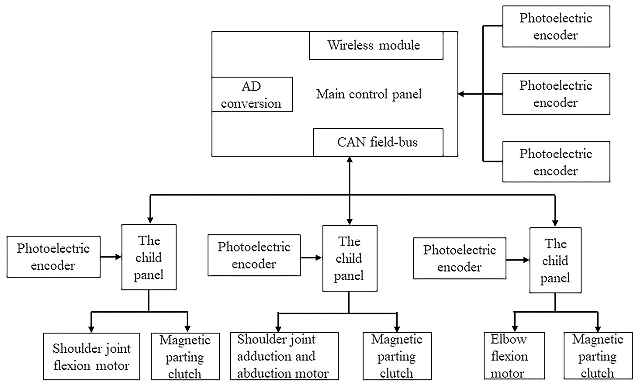
The required actuation units, photoelectric sensors, communication modules, and main control board are integrated into the seat base as presented in Fig. 2. The communication modules include the wireless communication module, the serial port communication module, and the CAN bus communication module. In order to improve the control response speed, this paper proposes a two-level control strategy. Three actuation units for the three DOFs consist of the actuator, the stepping motor, the first reduction gearbox, the magnetic powder clutch, and the second reduction gearbox. There are two kinds of magnetic powder clutches. One is FL50A (manufactured by Lanning Electromechanical Company; the maximum output torque is 50 N m), which is utilized to implement the rotation of the shoulder joint at the sagittal axis and the horizontal axis. The other one is FL25A (manufactured by Lanning Electromechanical Company; the maximum output torque is 25 N m), which is utilized to implement the rotation of the elbow joint at the horizontal axis. These three actuation units are controlled by the sub-controller. The main control board transforms the control information to the corresponding sub-controller by the wireless communication module. The photoelectric sensors (manufactured by Omron. E6B2-CWZ5G) are used to detect the position and the motion information of the manipulator in order to realize the real-time control of the robot. There are three photoelectric sensors placed at the motors to detect their motion states. Another three photoelectric sensors are placed at the second reduction gearbox to detect the motion of the end-effectors.
3.1 Workspace analysis
The kinematics analysis, as presented in Cao et al. (2018), can be used to deduce the kinematics equation for the proposed upper rehabilitation robot. According to the Denavit–Hartenberg (D–H) representation, this paper specifies the coordinate system for each link of the robot, as shown in Fig. 1a. The coordinate system {0} is the base coordinate system, the coordinate system {1} refers to the flexion/extension motion coordinate system of the shoulder joint, the coordinate system {2} is the shoulder joint adduction/abduction coordinate system, and the coordinate system {3} is the elbow joint flexion/extension coordinate system, and the coordinate system {4} is the coordinate system of the manipulator handle.
3.1.1 End-joint Jacobian matrix
The Jacobian matrix of the robot is based on the concept of a moving coordinate system. The mapping between robot terminal static force and joint torque can be realized by a Jacobian matrix. The linear velocity v and angular velocity ω of the robot terminal joint are still related to the velocity of each joint, and q is the joint variable. In this paper, the basis coordinates of the Jacobian matrix are selected as reference coordinates. The three motion joints of the central drive upper limb rehabilitation robot are revolute joints, and the Jacobian matrix of relative fundamental coordinates can be calculated as
Then we obtain the transformation of each connecting rod relative to the coordinate system {0} according to the obtained transformation matrix of each connecting rod and work out the expression of zi in the base coordinate system {0}, which is
The third column of the rotation matrix is the representation of zi at the basis coordinates {0}.
Equations (1) and (2) constitute the Jacobian matrix of the coordinate system {3} of the centrally driven upper limb rehabilitation robot relative to the base coordinate system {0}, which can be expressed as
3.1.2 The velocity vector of the manipulator handle
The speed of the manipulator handle is mainly controlled in the control process of the robot. Therefore, the velocity vector of the manipulator handle in Cartesian space needs to be solved by calculating the Jacobian matrix of the manipulator handle relative to the base coordinate system. The Jacobian matrix of the manipulator handle needs to be obtained according to the Jacobian matrix of the coordinate system {3} relative to the base coordinate system {0}. Assuming that the linear velocity of the manipulator handle is 0v4 and the angular velocity is 0ω4, then
I is the identity matrix, and is the antisymmetric matrix of the position vector of the robot coordinate system {4} relative to the coordinate system {3}.
According to the transformation matrix of each connecting rod, can be written as
Therefore, the Jacobian matrix 0J4 of the robot manipulator relative to the base coordinate system is
The Jacobian matrix of the robot manipulator handle coordinate system {4} is obtained relative to the base coordinate system {0}, and the velocity vector of the manipulator handle in Cartesian space can be obtained according to the velocities of each joint in the actual control process:
3.2 Trajectory planning
The Jacobian matrix of the robot's last joint and handle can be obtained by motion differentiation. The position of the robot's handle can be determined by knowing the joint variables and the corresponding joint variables, and speed can be determined by knowing the position of the robot's handle. It is necessary to carry out trajectory planning for the upper limb rehabilitation robot in order to enable the upper limb rehabilitation robot to compensate patients in the active training process. Trajectory planning is to calculate the expected trajectory according to the requirements; there are many studies on robot trajectory planning (Li et al., 2022; Madridano et al., 2021). The trajectory of the upper limb robot needs the robot to drive the patient's upper limb to carry out rehabilitation movement under the condition of ensuring safety. This paper only plans the displacement and speed of the upper limb robot, because the characteristics of the rehabilitation training need the robot to move slowly, stably, and repeatedly in active training mode.
In this paper, the trajectory planning of the upper limb rehabilitation robot is used for assisted training. With the help of the robot, patients with upper limb dysfunction actively exert force to make the affected limb move and complete certain movements. The position and acceleration information of the manipulator handle cannot be obtained directly, because the required upper limb rehabilitation robot moves slowly and there is no sensor for detecting the position of the manipulator handle. Therefore, this paper uses the cubic polynomial trajectory planning method to carry out trajectory planning. According to the present situation of upper limb rehabilitation training, this paper carries out rehabilitation trajectory planning according to the diamond movement commonly used in the rehabilitation process. We set each rehabilitation action into six segments in order to reduce the complexity of CPU calculation. The first segment is the process of powering up the robot to find the zero position of the angle sensor of each joint, and the remaining five segments are the process of returning from the initial position to the initial position. We recorded the joint angles through each joint sensor and calculated the cubic polynomial coefficients to obtain the rhomboid motion trajectory of the robot manipulator handle without a position sensor at the end of the handle. In the following two trajectory plans, θ1 represents the angle of flexion/extension motion of the shoulder joint, θ2 indicates the angle of shoulder adduction/abduction, and θ3 indicates the angle of elbow flexion/extension motion. Finally, the trajectory equations are obtained as a function of joint angle with respect to time.
4.1 Control strategy
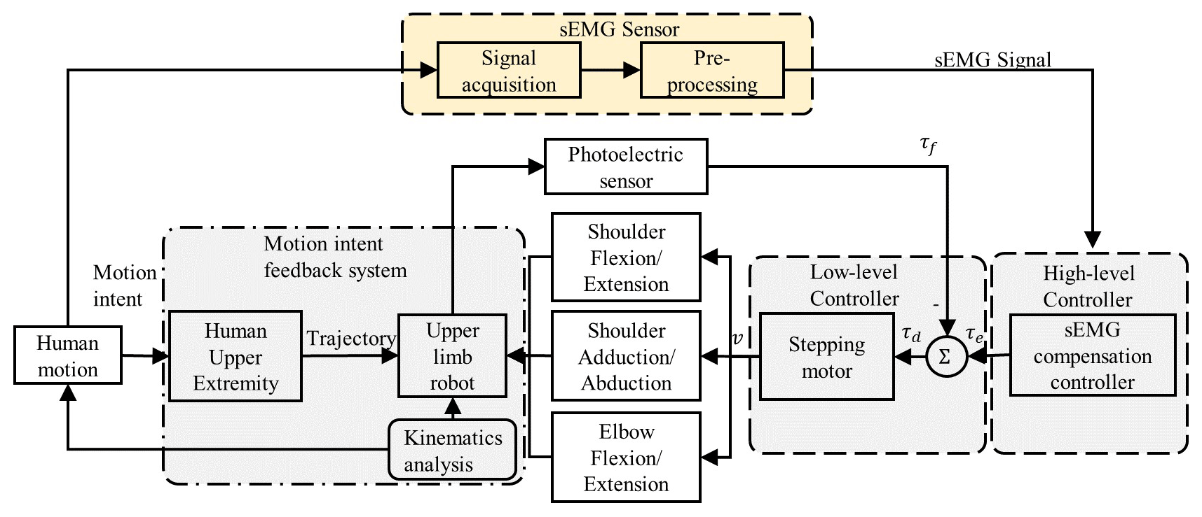
This paper proposes an EMG-based compensation control strategy for the center-driven upper limb rehabilitation robot in active training as shown in Fig. 3. The EMG-based compensation control strategy can implement the positive relationship between the rotating speed and the intensity of EMG that emerged. The rehabilitation robot can provide auxiliary force according to the patients' motion intents under the EMG-based control method. It consists of a high-level controller, a low-level controller, a motion intent feedback system, and a sEMG senor. This paper designed a sEMG sensor to acquire and pre-process the sEMG signal. The sEMG sensor collects the raw sEMG signal from the human upper limb when human motion appears according to the reference trajectory. Then the signal will be pre-processing by the sensor instantly. The high-level controller is a sEMG compensation controller in order to transform the sEMG signal to the input signal of the stepping motor. The stepping motor controls the 3-DOF robot arm of the upper limb robot. The motion intent feedback system tracks the users' motion intent of the human upper limb, and the upper limb rehabilitation robot will provide motion compensation according to the motion intent and the data of kinematics analysis. The motion signal of the upper limb robot is also collected by the photoelectric sensor. The signals are sent back to the low-level controller to complete the closed loop control.
4.2 EMG sensor design
This paper designs an EMG sensor with a single channel to detect the motion intents of the upper limb in active training. The designed EMG sensor consists of an acquisition module and a pre-processing module in order to detect and output the EMG signal effectively in real time. The acquisition module is designed as a front-end gain amplification circuit for the obtained EMG signals from the upper limb as shown in Fig. 4. The method of multistage amplification is utilized in this paper in order to prevent the signal distortion caused by amplifier saturation. The signal E(s) introduced through the surface electrode are fed into the high-input impedance buffer amplifiers Kb1. The buffer amplifiers are mainly used to improve the load capacity and reduce the influence of load on the signal source and increase the anti-interference ability. This paper adopts an instrument amplifier (AD620, ADI company) to implement the differential amplifier Kp1 with a high common-mode rejection ratio. In order to amplify further the signals, an in-phase proportional amplifier Kp2 is designed here. Then, an adjustable double T notch trap with positive feedback is adopted in this paper. The filter frequency is chosen as 50 Hz. The transfer function G1(s) can be expressed as
ω0 is the cut-off angular frequency, and K is the amplification coefficient.
Finally, another buffer amplifier Kb2 is designed at the end of this acquisition module to ensure the stability and accuracy of the output signal U01(s).

The pre-processing module is designed as a filter amplification circuit as shown in Fig. 5. Signal U01(s) is introduced through the RC high-pass filter to filter the low-frequency signals below 20 Hz. Its transfer function G2(s) is expressed as follows:
where GT1 is the passband gain.
Then, this paper designs a low-pass filter with 200 Hz. The signals passing through the 20 Hz high-pass filter are filtered through the RC low-pass filter to filter the high-frequency signals above 200 Hz. The transfer function of the low-pass filter G3(s) is expressed as follows:
where GT2 is the passband gain.

Before the EMG signal is processed in the digital circuit, this paper designs a first-stage gain amplifier Kp3 to fit different strengths of the EMG signal. The gain-adjustable circuit can be used to increase the overall amplification for people with a weak signal strength. It can also be used to reduce the amplification to meet the needs of control for people with a large signal strength. The buffer amplifiers Kb3 amplify the signal further. Therefore, the EMG signal can be used to control the upper limb robot by taking the absolute value of the signal through Kb3.
4.3 EMG-based compensation controller
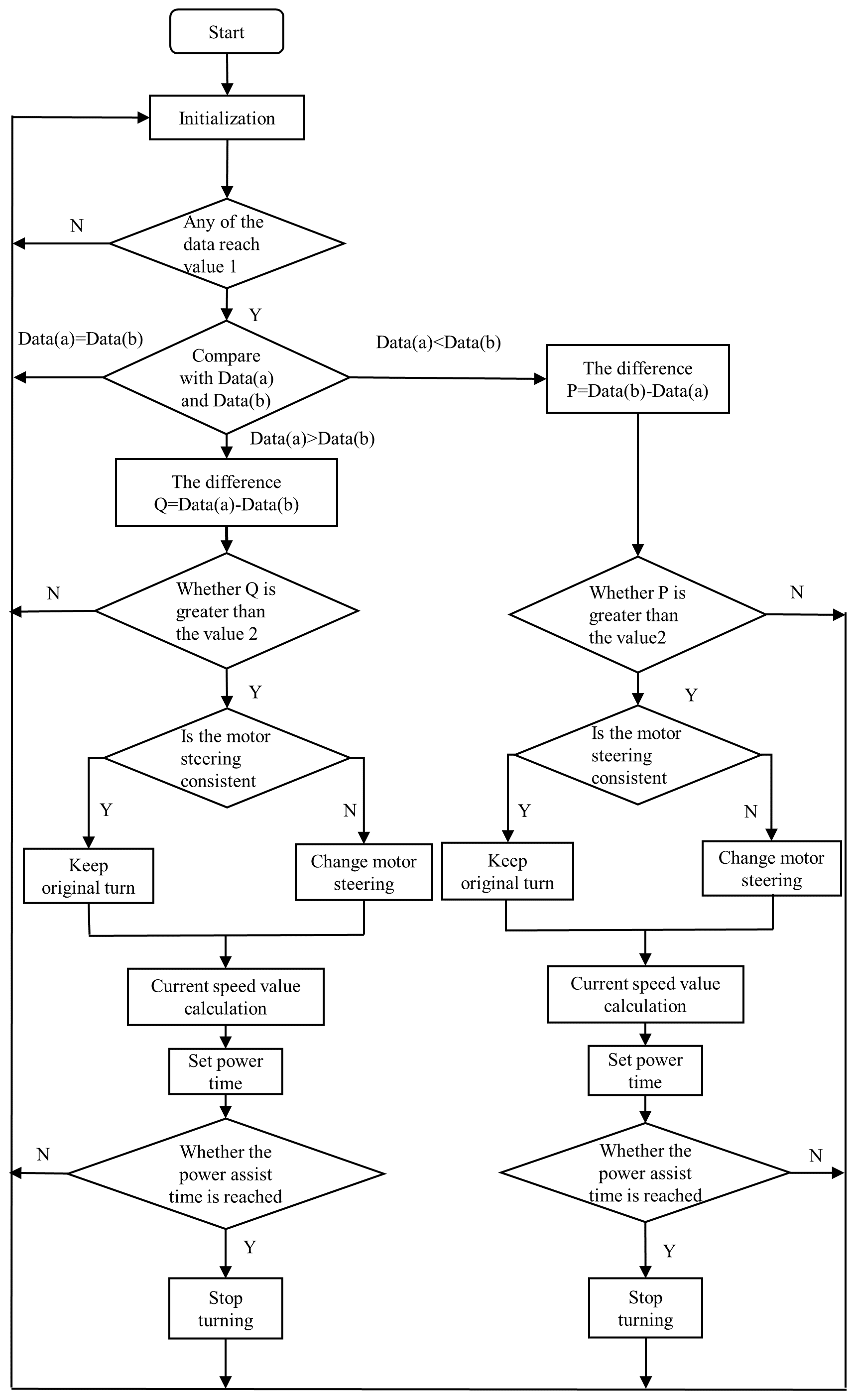
The EMG-based compensation controller judges the exercise intention by detecting the patients' EMG signals. We propose a method to determine the direction of movement by comparing two channels of EMG signals detected from the upper limb. In the design, as shown in Fig. 6, the intensity of the two channels of the EMG signal is utilized firstly to judge whether their values reach the starting value of 1. If any of them reaches the starting value of 1, the next judgement is entered. The judgment is to compare the size of the two signals. Then the process will go back to initialization if data(a) is equal to data(b) or take the difference between data(a) and data(b) if data(a) is not equal to data(b). Then the next judgement will judge whether their difference value reaches the starting value of 2. If the difference is greater than the starting value of 2, the motor can be controlled after the motor steering is judged.
In the process of active training, the intensity of EMG is adopted to express the upper limb motion intents. The motor rotating speed is constructed as the function of the intensity of EMG produced by the upper limb. The relationship between the motor rotating speed and the intensity of EMG is positive because that EMG signal is utilized to describe the motion intents in real time. The maximum intensity, as for a patient, shows the strongest motion intents. Therefore, the patients can do their best in their rehabilitation training. The relationship function is
where n is the motor rotating speed, and ve is the intensity of the EMG signal.
The prototype of the central drive upper limb rehabilitation robot is shown in Fig. 1b. There are two experiments carried out to verify the proposed control strategy.
5.1 EMG-based compensation experiment
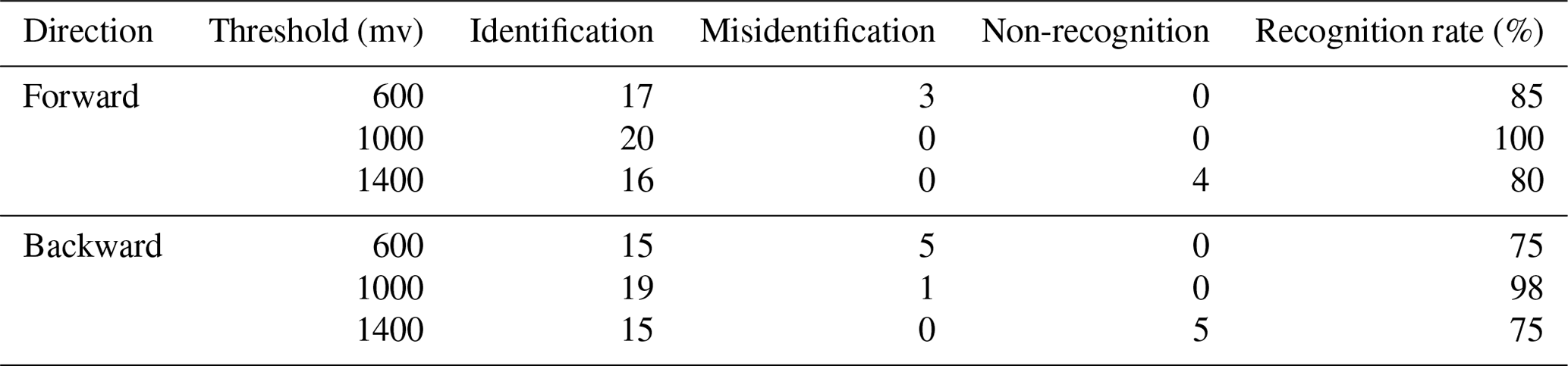
In the EMG-based compensation experiment, we chose the flexion and extension of the shoulder joint as the experimental object of active training. We extracted the EMG signals of normal people's arms. For different patients, the optimal threshold value is different, and the selection of the threshold value directly affects the degree of completion of training movements. The threshold values of 600, 1000, and 1400 mV were set as the maximum detected intensity of EMG in this paper. The subject was required to force his arm upward and downward for 20 times, respectively. The recognition times, misrecognition times, and non-recognition times are recorded, respectively, as shown in Table 1. The recognition accuracy of the EMG-based controller can reach 98 %. The theoretical and experimental relationships between motor rotating speed and intensity of EMG are shown in Fig. 7. The maximum error is no more than 1.3 %. The result shows the characteristic of motion compensation in real time based on the EMG signal. The distribution of experimental data in Fig. 7 is close to the given linear change, but there is a certain error. This is because, in the experiment, the change in the EMG signal is used to indicate the movement consciousness of the subject, which is not a uniform change. When the EMG intensity is 0, the motor will stop rotation in a very short time. It also shows that the control strategy can guarantee patients' safety in active training.

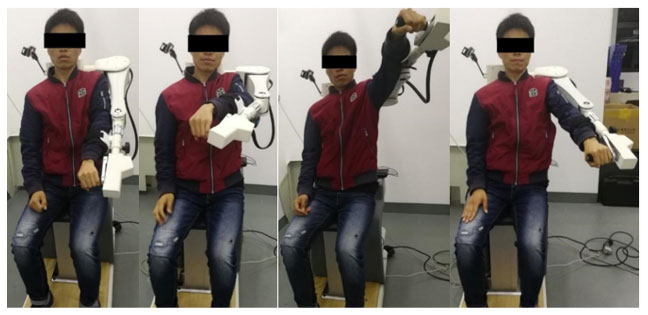
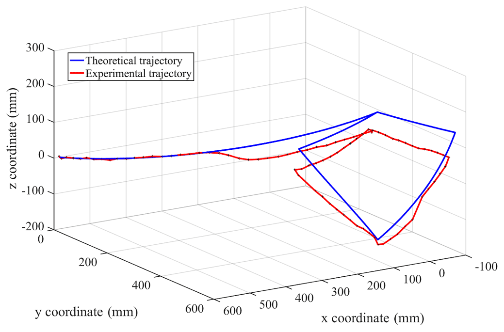
5.2 Active training control experiment
To draw a diamond active training that is chosen in this work, first, the trajectory of drawing a diamond task is defined according to Sect. 3. Then, the trajectory is defined as the referring trail in the control system. Finally, adults without upper limb dysfunction were selected as subjects to draw a diamond actively under the active training mode of the robot (Fig. 8). In the process of the experiment, the robot provides auxiliary force according to the subjects' motion intents. The experiment result includes 96 groups of data of () coordinates, which shows a complete diamond drawing active training. The end-effector trajectory is shown in Fig. 9 together with the theoretical trajectory. The experiment curves are almost the same as the theoretical trajectory drawn above. It shows that trajectory input by the EMG signal can help compensate the active movement when completing the training action. The experimental curve does not coincide exactly with the actual curve, because as in Sect. 5.1, there is no more than 1.3 % error between the motor rotating speed and the intensity of EMG. Such errors do not affect the training effect.
Even if only one degree of freedom of a pair of antagonist muscle shoulder joint-assisted triggering training is temporarily realized in this paper, it is also necessary to realize the power-assisted training of all DOFs of the rehabilitation robot corresponding to muscles.
The main contributions of this paper are as follows. This paper proposes an EMG-based motion compensation control method for the upper limb rehabilitation robot in active training in order to improve the patients' active participation. A center-driven upper limb rehabilitation robot is proposed at first. The trajectory planning equations for the proposed robot manipulator are analyzed and built in order to provide the reference trajectory in active training. On this basis, this paper proposes an EMG-based motion compensation controller in active training control to improve patients' active participation. In the end, two experiments are carried out to verify the proposed control method. The EMG compensation experiments show that the maximum error between the theoretical and experimental motor rotating speeds is no more than 1.3 %. The active training control experiment results show that it can implement the reference trajectory in real time. The control method proposed in this paper can implement the positive relationship between the rotating speed and the intensity of EMG that emerged during upper limb training. This shows that the proposed rehabilitation robot can provide auxiliary force according to the patients' motion intents. The proposed rehabilitation robot can guide the patients in implementing the reference task in active training. The control strategy in this paper improves the present situation in a traditional upper limb rehabilitation robot. It can improve the rehabilitation effect for patients with upper limb dysfunction and the patients' active participation in active training. In addition, the proposed control method can be applied to other control systems requiring motion compensation under given trajectories.
All raw data can be provided by the authors upon request.
QM proposed and developed the overall concept of the paper and conducted the mechanical and electronic design and analysis. YY helped write and edit the paper. HY supervised and structured the paper. SL helped process the data.
The contact author has declared that none of the authors has any competing interests.
Publisher's note: Copernicus Publications remains neutral with regard to jurisdictional claims in published maps and institutional affiliations.
The authors are grateful for the financial support from the National Natural Science Foundation of China (grant no. 61903255) and the Shanghai Science and Technology Development Foundation, China (grant no. 20S31905400).
The research has been supported by the National Natural Science Foundation of China (grant no. 61903255) and the Shanghai Science and Technology Development Foundation, China (grant no. 20S31905400).
This paper was edited by Wuxiang Zhang and reviewed by three anonymous referees.
Bai, J., Song, A., Wang, T., and Li, H.: A novel backstepping adaptive impedance control for an upper limb rehabilitation robot, Comput. Electr. Eng., 80, 106465, https://doi.org/10.1016/j.compeleceng.2019.106465, 2019.
Bertani, R., Melegari, C., De Cola, M. C., Bramanti, A., Bramanti, P., and Calabrò, R. S.: Effects of robot-assisted upper limb rehabilitation in stroke patients: a systematic review with meta-analysis, Neurol. Sci., 38, 1561–1569, https://doi.org/10.1007/s10072-017-2995-5, 2017.
Brahmi, B., Saad, M., Luna, C. O., Archambault, P. S., and Rahman, M. H.: Passive and active rehabilitation control of human upper-limb exoskeleton robot with dynamic uncertainties, Robotica, 36, 1757–1779, https://doi.org/10.1017/S0263574718000723, 2018.
Büsching, I., Sehle, A., Stürner, J., and Liepert, J.: Using an upper extremity exoskeleton for semi-autonomous exercise during inpatient neurological rehabilitation-a pilot study, J. Neuroeng. Rehabil., 15, 1–7, https://doi.org/10.1186/s12984-018-0415-6, 2018.
Cao, W., Zhang, F., Yu, H., Hu, B., and Meng, Q.: Preliminary research of a novel center-driven robot for upper extremity rehabilitation, Technol. Health Care., 26, 409–420, https://doi.org/10.3233/Thc-171060, 2018.
Cao, W., Chen, C., Wang, D., Wu, X., Chen, L., Xu, T., and Liu, J.: A Lower Limb Exoskeleton with Rigid and Soft Structure for Loaded Walking Assistance, IEEE Robotics and Automation Letters, 7, 454–461, 2021.
Cui, X., Chen, W., Jin, X., and Agrawal, S. K.: Design of a 7-DOF cable-driven arm exoskeleton (CAREX-7) and a controller for dexterous motion training or assistance, IEEE-ASME T. Mech., 22, 161–172, https://doi.org/10.1109/TMECH.2016.2618888, 2016.
Disselhorst-Klug, C., Schmitz-Rode, T., and Rau, G.: Surface electromyography and muscle force: Limits in sEMG–force relationship and new approaches for applications, Clin. Biomech., 24, 225–235, https://doi.org/10.1016/j.clinbiomech.2008.08.003, 2009.
Furukawa, A., Uchida, M., Noguchi, Y., Ito, T., and Aso, C.: Measurement of patient's upper limbs motor characteristics using upper limb rehabilitation support system, Measurement: Sensors., 18, 100097, https://doi.org/10.1016/j.measen.2021.100097, 2021.
Iosa, M., Galeoto, G., De Bartolo, D., Russo, V., Ruotolo, I., Spitoni, G. F., Ciancarelli, I., Tramontano, M., Antonucci G., Paolucci, S., and Morone, G.: Italian Version of the Pittsburgh Rehabilitation Participation Scale: Psychometric Analysis of Validity and Reliability, Brain Sci., 11, 626, https://doi.org/10.3390/brainsci11050626, 2021.
Jakob, I., Kollreider, A., Germanotta, M., Benetti, F., Cruciani, A., Padua, L., and Aprile, I.: Robotic and sensor technology for upper limb rehabilitation, Physical Medicine and Rehabilitation, 10, S189–S197, https://doi.org/10.1016/j.pmrj.2018.07.011, 2018.
Khezri, M. and Jahed, M.: An inventive quadratic time-frequency scheme based on Wigner-Ville distribution for classification of sEMG signals, in: IEEE 6th International Special Topic Conference on Information Technology Applications in Biomedicine, 261–264, https://doi.org/10.1109/ITAB.2007.4407397, 2007.
Li, Z., Peng, F., Yan, R., Tang, X., Xin, S. and Wu, J.: A virtual repulsive potential field algorithm of posture trajectory planning for precision improvement in robotic multi-axis milling, Robot. CIM-Int. Manuf., 74, 102288, https://doi.org/10.1016/j.rcim.2021.102288, 2022.
Liu, K., Xiong, C. H., He, L., Chen, W. B., and Huang, X. L.: Postural synergy based design of exoskeleton robot replicating human arm reaching movements, Robot. Auton. Syst., 99, 84–96, https://doi.org/10.1016/j.robot.2017.10.003, 2018.
Madridano, Á., Al-Kaff, A., Martín, D., and de la Escalera, A.: Trajectory planning for multi-robot systems: Methods and applications, Expert Syst. Appl., 173, 114660, https://doi.org/10.1016/j.eswa.2021.114660, 2021.
Mead, N. and Bower, P.: Patient-centredness: a conceptual framework and review of the empirical literature, Soc. Sci. Med., 51, 1087–1110, https://doi.org/10.1016/S0277-9536(00)00098-8, 2000.
Molteni, F., Gasperini, G., Cannaviello, G., and Guanziroli, E.: Exoskeleton and end-effector robots for upper and lower limbs rehabilitation: narrative review, Physical Medicine and Rehabilitation, 10, S174–S188, https://doi.org/10.1016/j.pmrj.2018.06.005, 2018.
Reddy, N. P. and Gupta, V.: Toward direct biocontrol using surface EMG signals: Control of finger and wrist joint models, Med. Eng. Phys., 29, 398–403, https://doi.org/10.1016/j.medengphy.2005.10.016, 2007.
Sbriccoli, P., Bazzucchi, I., Rosponi, A., Bernardi, M., De Vito, G., and Felici, F.: Amplitude and spectral characteristics of biceps Brachii sEMG depend upon speed of isometric force generation, J. Electromyogr. Kines., 13, 139–147, https://doi.org/10.1016/S1050-6411(02)00098-6, 2003.
Shi, D., Zhang, W., Zhang, W., and Ding, X.: A review on lower limb rehabilitation exoskeleton robots, Chin. J. Mech. Eng., 32, 1–11, https://doi.org/10.1186/s10033-019-0389-8, 2019.
Wang, Y., Wu, Q., Dey, N., Fong, S., and Ashour, A. S.: Deep back propagation–long short-term memory network based upper-limb sEMG signal classification for automated rehabilitation, Biocybern. Biomed. Eng., 40, 987–1001, https://doi.org/10.1016/j.bbe.2020.05.003, 2020.
Wu, X., Cao, W., Yu, H., Zhang, Z., Leng, Y., and Zhang, M.: Generating Electricity during Locomotion Modes Dominated by Negative Work with a Knee Energy Harvesting Exoskeleton, IEEE-ASME T. Mech., https://doi.org/10.1109/TMECH.2022.3157848, online first, 2022.