the Creative Commons Attribution 4.0 License.
the Creative Commons Attribution 4.0 License.
 | 07 Jun 2022
Kinematics and control of a cable-driven snake-like manipulator for underwater application
Fufeng Xue
Zhimin Fan
In view of the large volume, complex structure, and poor performance of traditional underwater manipulators in some complicated underwater scenarios, a cable-driven snake-like manipulator (CDSLM) is proposed. In this paper, the kinematics model of the proposed CDSLM is firstly established, which can be decomposed into three parts: motor–cable kinematics, cable–joint kinematics, and joint–end kinematics. A tip-following algorithm is then presented to weave through the confined and hazardous spaces along a defined path with high efficiency. The main merit of the algorithm is that only the terminal section variables need to be calculated and recorded, which solves the problem of expensive computational cost for the inverse kinematics of snake-like manipulators. Finally, evaluation indexes of the path-following performance are proposed to evaluate the effect of the tip-following algorithm. Simulations of the path-tracking performance are carried out using MATLAB. The results demonstrate that the average computation time is about 1.6 ms, with a deviation of less than 0.8 mm from the desired path, and the stability and effectiveness of the tip-following algorithm are verified.
- Article
(1062 KB) - Full-text XML
-
Supplement
(480 KB) - BibTeX
- EndNote


Humankind has turned its attention to the vast ocean due to the region's abundant mineral and biological resources (Brito et al., 2019; Liu et al., 2018). Underwater manipulators play an irreplaceable role in the development of marine resources. To date, most underwater manipulators have been rigid-link structures with a small number of degrees of freedom (DOFs) (Barbieri et al., 2018) and have not performed well in confined spaces. With the development of deep-sea equipment, marine structures, such as deep-sea laboratories, deep-sea space stations, and deep-sea cities, have emerged. Their operation, construction, and maintenance will inevitably involve some complicated underwater environments, such as deep cavities, pipe networks, and other confined and hazardous spaces. Therefore, there is an urgent need for a lightweight underwater manipulator with superior dexterity and good obstacle avoidance capabilities in the complex underwater environment.
Due to their high dexterity and strong adaptability to environment, hyper-redundant manipulators have great advantages with respect to obstacle avoidance. This had made them tremendously fascinating in numerous research fields, and they have already been used in practice in fields such as inspection, maintenance, assemblage, repair, and so on, in nuclear reactors (Wu et al., 2015), aircraft (Dong et al., 2017), minimally invasive surgery (Cianchetti et al., 2014; Kai and Simaan, 2010; Li et al., 2017), and other fields (Tang et al., 2019a; Xu et al., 2020). Generally, hyper-redundant manipulators can be grossly classified into two types: (1) discrete manipulators with multiple rigid links (Tang et al., 2017) and (2) continuum manipulators with multiple segmented elastic backbones (Hu et al., 2010). The kinematics modeling for continuum manipulators is based on the piecewise constant curvature assumption (Tang et al., 2019; Yan et al., 2018), and the effects of gravity and external loads are ignored. Hence, it is hard to accurately depict the real position of a continuum manipulator in some cases. Compared with a continuum manipulator, a discrete manipulator with multiple rigid links has a stronger payload capacity and motional accuracy (Cao et al., 2012), and the elastic materials are easily affected by various factors, such as high pressure and corrosion, which is not conducive to operations in marine environments. Therefore, the focus of this paper is a cable-driven snake-like manipulator (CDSLM) composed of multiple rigid links and joints. Due to the large number of DOFs, small size, and the fact that it does not require a complex sealing structure, the snake-like manipulator has strong potential for use in complex marine applications.
In contrast to traditional underwater manipulators that have the actuators installed directly at the joints, a cable-driven mechanism permits the actuators to be mounted remotely from the joints; therefore, the weight of the manipulator is effectively reduced. To date, most existing cable-driven manipulators have mainly been for land applications (Tang et al., 2019) and usage in the underwater environment has been rare. Recently, Li et al. (2019) presented a novel underwater cable-driven manipulator for autonomous underwater vehicles, but the structure did not break away from the shackles of traditional manipulators and could not perform well in confined spaces. Therefore, a light-weight CDSLM with superior dexterity and large maneuverability will inevitably become the focus of research on manipulators in complicated underwater environments.
Many efforts have been made to improve the obstacle avoidance ability of hyper-redundant robots. Conkur et al. (2003) explored how to follow the planar line using hyper-redundant manipulators, and Tanaka et al. (2015) presented an approximate path-tracking control method for a wheeled snake robot. However, these studies were mainly applicable to the planar path. Palmer et al. (2014) presented a tip-following method that used the sequential quadratic programming optimization approach and created the objective function to minimize the deviation from the desired path, but they still had the problem of a huge computational cost. Andersson et al. (2008) used the bisection search method to find the location of the points along the curve, but the efficiency of this method is affected by the initial values. Tang et al. (2019b) proposed a two-level motion-planning method to improve the tracking accuracy and motion smoothness of a cable-driven snake robot; however, the study did not give a specific implementation in confined spaces. Bulut and Conkur (2021) presented a real-time path-planning algorithm for hyper-redundant manipulators, and their paper focused on the instrument's maneuvering capabilities.
Based on the idea of discretization, a tip-following algorithm is proposed in this work. The main advantage is that only the terminal section variables of the CDSLM need to be solved, which addresses the computational cost problem for the inverse kinematics of hyper-redundant manipulators. Evaluation indexes are proposed to assess the effects of the tip-following algorithm: these are the tracking error and response time. Simulations are analyzed in MATLAB, and the results show that the algorithm can follow the given path effectively.
2.1 Overall design of the CDSLM robot system
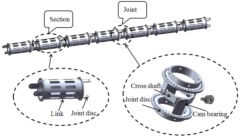
In this work, a novel CDSLM is designed to perform specific tasks in some complicated underwater scenarios. It is composed of seven sections with 2DOFs, and each section includes two joint discs and a link, as depicted in Fig. 1. Considering the working environment of the CDSLM, the 6061-T6 aluminum alloy is used in joints and links. No driving motors are installed at the joints, and the links can be designed as a permeable structure so that the water resistance under the same size condition will be further reduced, thereby weakening the coupling effect between the manipulator and the underwater vehicle (Chang et al., 2020).
Unlike the traditional underwater manipulators that have the actuators mounted directly on the joints, the cables are used to transmit mechanical power from the motors to joints. Usually, a cable is driven by a servomotor (Peng et al., 2021). However, this structure requires too many motors, which leads to an oversized drive device and high energy consumption. In this paper, the gear-rack structure is adopted, and each drive unit controls two cables simultaneously, which minimizes the number of motors. The drive unit is depicted in Fig. 2.
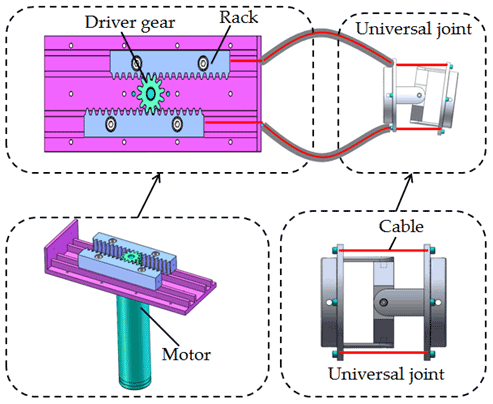
Due to the structure of the CDSLM, a mutual coupling exists between the cables. To counter the coupling effect caused by joints, Xu et al. (2018) and Hu et al. (2010) compensated for the changes in cable length using the movement of the corresponding motors. However, this increases the control difficulty and the computation requirements, thereby affecting the real-time performance of the CDSLM. The cable in this study adopts a structure similar to the brake cable on bicycles. The brake cable on bicycles consists of a protective sheath and an internal transmission cable with relative motion, which is a typical cable–sheath transmission system. The cable length does not change with the shape of the sheath. Based on this advantage, the cable–sheath mechanism is widely used for long-distance power transmission.
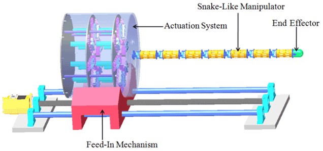
The CDSLM robot system consists of a snake-like manipulator, an actuation system, an end effector, and a feed-in mechanism, as shown in Fig. 3.
2.2 Multilevel mapping relationships of the CDSLM
For a CDSLM with n sections, the multilevel mapping relationships among the motors, cables, joints, and end effector can be described as shown in Fig. 4, which can be decomposed into motor–cable kinematics, cable–joint kinematics, and joint–end kinematics.

2.3 Motor–cable kinematics
Four cables are used to control the 2 DOFs of motion in each section. The two cables with an interval angle of 180∘ are controlled by a servomotor. The relationship between the motor angle and the cable length is as follows:
where D=18 mm and I=84 are the pitch circle diameter of the drive gear and the reduction ratio of the reducer, respectively; Δl and Δθi denote the variations in the cable length and motor angle, respectively.
2.4 Cable–joint kinematics
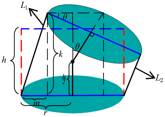
To describe the relationship between the cable lengths and the joint variables, a geometric model of a single joint is created, as shown in Fig. 5. The two red dotted lines denote the state of the cables when the joint is not rotating; the two solid black lines indicate the state of the cables after the joint has rotated; h is the joint distance; L1, L2 represents the length of the cables after rotation; r is the distance from the cable to the center of the joint; θ is the joint rotation angle;
The relationship between length variable and the joint angle is as follows:
According to the mechanical design, the following relationship exists:
2.5 Joint–end kinematics
In order to establish the mapping relationship from the joint space to the operation space, the Denavit–Hartenberg (D–H) method is utilized. The coordinate system of each section is defined as shown in Fig. 6, and the corresponding D–H parameters of the CDSLM are listed in Table 1. The CDSLM consisted of seven joints and eight key points (joint center K1–K7 and the terminal point K8).
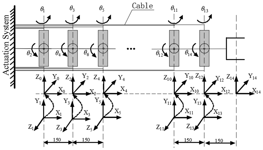
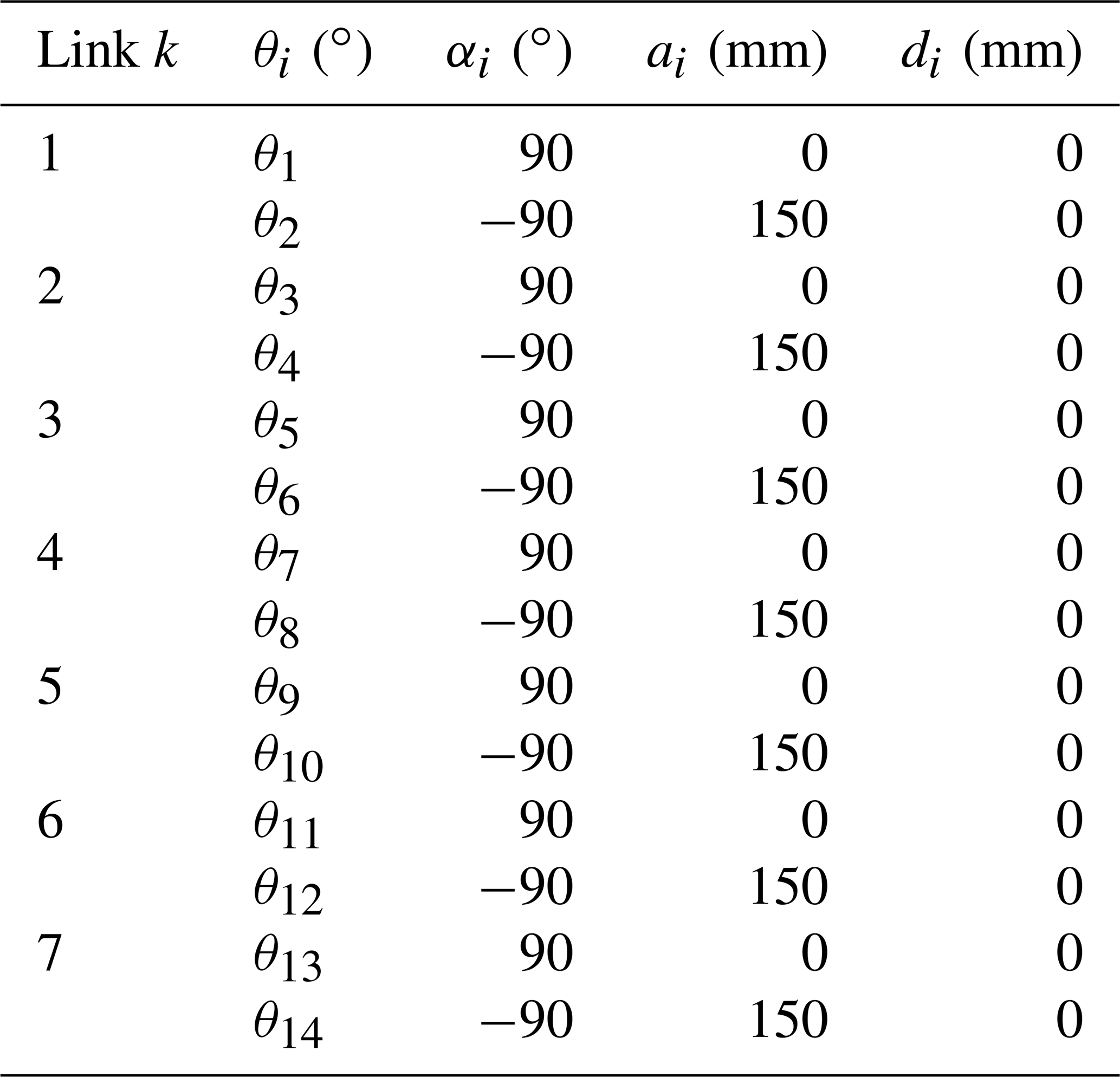
According to the D–H rules, the homogeneous transformation matrix between the frame {i+1} and {i} can be denoted as follows:
For hyper-redundant manipulators, the tip-following algorithm can perform well in space-constrained environments. The terminal section to enter the work environment is regarded as the base until the feed-in mechanism has advanced enough to consider a new section. The joint variables of the terminal section are calculated and recorded after the feed-in mechanism advances one step, and the joint variables of the subsequent sections can be obtained directly from the recorded data when they reach the same position. Like the snake game, each section of the snake takes up the position of the previous one as it chases the food with its head. Therefore, the key issue of the tip-following algorithm is to calculate and record the joint variables of the terminal section when the feed-in mechanism progresses one step. The tip-following algorithm has three main parts: path planning, the yardstick method, and the inverse resolution.
3.1 Path planning
Path planning refers to choosing an effective path with the least cost and making it collision-free from the start point to the target point in confined spaces. In this work, path planning is not a focal point, and we pay more attention to the tip-following algorithm with a well-defined environment. The equal arc length method is used to generate discrete points of the desired path curve; the discrete points are ordered, and the first point from the beginning is P1.
3.2 The yardstick method
The key points of the CDSLM should be matched with the discrete points on the desired path. Assuming that the length of a single section is L and the step value of the actuation system is s, the number of steps required to consider a new section is shown as follows:
The yardstick method is proposed to match the key point K8 and the discrete point Pi,j (; ). In the initial state, the terminal point K8 coincides with start point P1, and the positions of the key points K1–K8 are known. An example is given to explain the yardstick method.
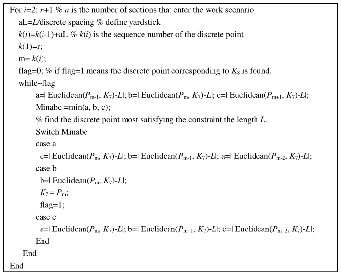
As shown in Fig. 7, when the feed-in mechanism advances a step from the initial state, it must find a discrete point that meets the length constraint (i.e., it makes a circle with L as the radius and the key point K7 as the center) to search for discrete point P1,1. Taking discrete point P1,1 as the center and the length L as the radius, the system then finds the discrete point P2,1. Subsequently, can be found in the same way. The feed-in mechanism then advances a step. When the key point K8 coincides with point P2,1, the position of K7 coincides with P1,1, and the joint variables of section S6 are the same as for terminal section S7 at this position. The pseudo-code of the yardstick method is presented in Fig. 8.

The distance between the discrete points found by the yardstick method may not exactly equal L due to the discretization. In this paper, an interpolation method is proposed to reduce the tracking error.
As shown in Fig. 9, Pm−1, Pm, and Pm+1 are three candidate points (m is the discrete point number), and the lengths of K7Pm−1 and K7Pm are dm−1 and dm, respectively. It can be seen from Fig. 9 that Pm is the best point for the length constraint found by the yardstick method. If the length constraint is performed strictly, point A is the point that satisfies the constraint of . However, the real position of point A cannot be found due to the discretization.
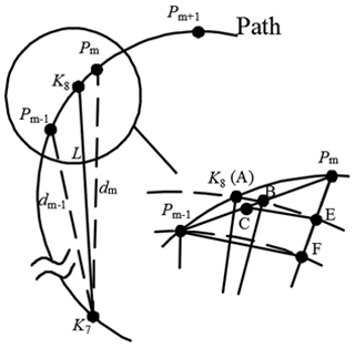
Points A, B, and C are on the line Pm−1Pm, which satisfies the constraint of . The position of point B cannot be obtained directly, so we approximately replace it with point C. According to the geometric relationship, Eq. (8) can be obtained, and the position of C can be denoted using Eq. (9).
Point C obtained by Eq. (9) is a little different from point B. To simplify the calculation, point C is considered to meet the accuracy requirement.
3.3 Inverse resolution
The task of solving inverse kinematics for a CDSLM is quite challenging due to its hyper-redundancy. This section discusses how to calculate the joint variables based on the positions of the key points obtained in Sect. 3.2. With the kinematics transformation matrix, the relationship between the x axes of sections Sk+1 and Sk can be obtained as follows:
, and . Thus, the joint angles of the terminal section can be denoted as follows:
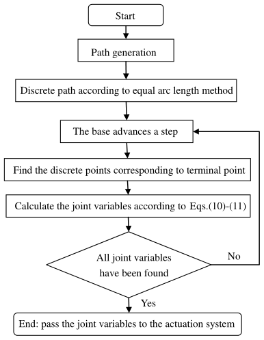
The inverse kinematics for the CDSLM is transformed into the inverse kinematics of the terminal section Sn with 2 DOFs. The decomposition process is carried out as follows. When the terminal section Sn follows the first segment of the path, the joint variables of the first (n−1) sections are zero. For each step of the feed-in mechanism, the joint variables of Sn are calculated and recorded. When the subsequent sections reach the same position, these data can be given to the sections from the database directly. When Sn follows the second segment of the path, the joint variables of Sn are calculated and recorded. Sn−1 follows the first segment of the path simultaneously and replicates the joint variables of Sn at this location. This method only solves the joint variables of the terminal section Sn, which solves the huge calculation requirement issue of the inverse kinematics of snake-like manipulators. A flowchart of the tip-following algorithm is shown in Fig. 10.
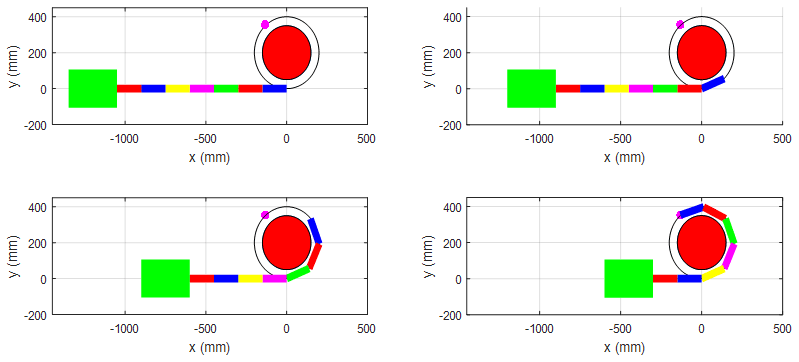
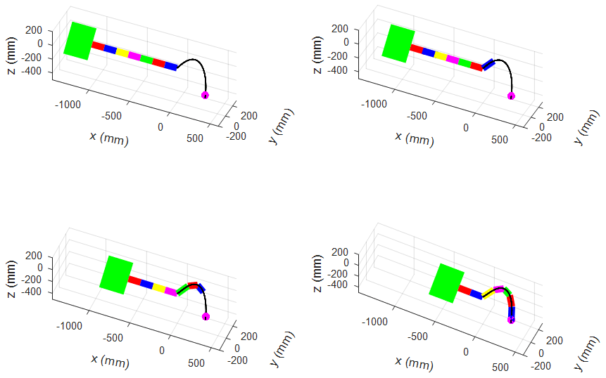
Simulations of the tip-following algorithm are performed on a standard commercial desktop running an i5-6500 (3.2 GHz) processor to verify the effectiveness of the proposed algorithm. Figures 11 and 12 show the CDSLM following the defined planar and space paths, respectively.
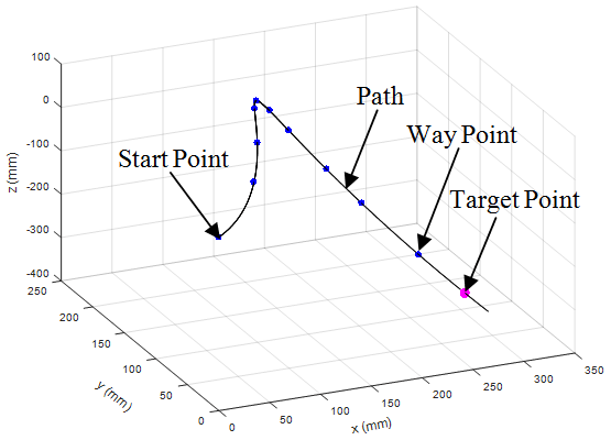
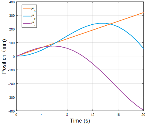
The tracking error and response time are proposed to evaluate the performance of the tip-following algorithm. Without losing generality, this study tracks a spiral path, as shown in Fig. 13. The length of each section is 150 mm, and the step value is 6 mm. There are 125 steps in total, and each step is 160 ms. The space path can be expressed as follows:
where Curve_x, Curve_y, and Curve_z represent the respective x, y, and z coordinates of points on the curve, and t is the curve parameter.
4.1 Response time
The response time refers to the time required to find the discrete points according to the yardstick method and to calculate the joint variables of the CDSLM, which are used to measure the real-time performance of the tip-following algorithm. To minimize the calculation time, one must ensure that this algorithm only performs the necessary calculations. The tip-following algorithm only calculates the joint variables of the terminal section and ignores the parameters of the sections that do not enter the working environment. This is beneficial and greatly reduces the computation time. For a snake-like manipulator with 14 DOFs, the computation time spent finding the discrete points that correspond to the key points using the optimization method (Palmer et al., 2014), the bisection method (Niu et al., 2014), and yardstick method are listed in Table 2.

4.2 Tracking error
The tracking error represents the distance between the terminal point K8 and the defined path. For each step, only the joint variables of the terminal section need to be solved. Therefore, the actual position of the terminal point K8 is calculated by forward kinematics with the joint variables obtained by Eq. (11). Finally, the distance between the key point K8 and the defined path is calculated.
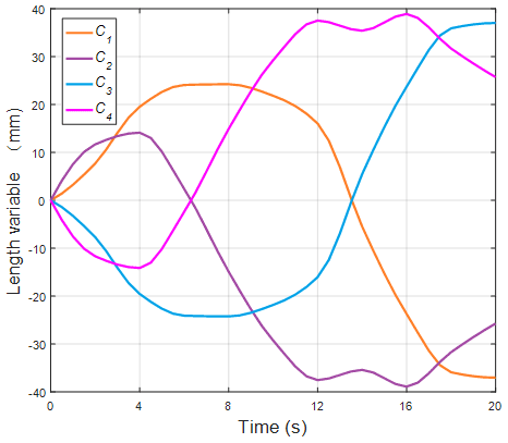
The position of the key point K8 is shown in Fig. 14. The length changes of cables for the terminal section are shown in Fig. 15. Figure 16 shows the detailed error.
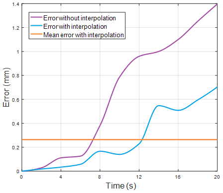
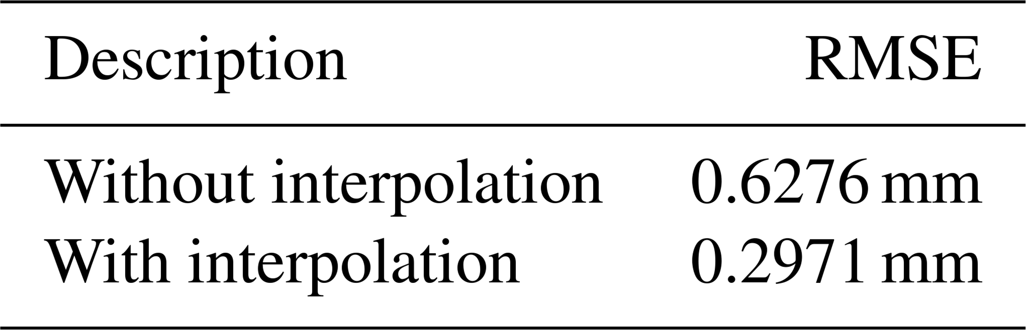
It can be seen from Fig. 16 that the tracking error increases with time. This article considers that the error reaches its maximum at the termination time. These results indicate that the interpolation method can effectively reduce the tracking error: the maximum error with interpolation is less than 0.8 mm, and the mean error is less than 1 % of the total length of the manipulator. The root-mean-square error (RMSE) of the terminal point with and without interpolation are shown in Table 3, and the results show that the RMSE with interpolation is reduced by about 52 %.
In this paper, a novel cable-driven snake-like manipulator (CDSLM) with large maneuverability and superior dexterity is designed. This CDSLM has strong potential for some complicated underwater applications.
The multilevel mapping relationships between the control space, drive space, joint space, and operation space are clearly described, and the corresponding kinematics equations are derived and solved by combining numerical and analytical approaches.
A tip-following algorithm is proposed to improve the efficiency of the CDSLM's motion in complicated underwater scenarios. The algorithm composes three steps: path generation, the yardstick method, and inverse kinematics. The yardstick method is presented in order to match the key point K8 and the discrete points. Meanwhile, an interpolation method is proposed to reduce the errors caused by the discretization. For a CDSLM robot with seven sections, the average calculation time is 1.6 ms, with a mean error of less than 1 %. Thus, this method can be used for real-time control of the CDSLM robot.
All data included in this study can be requested from the corresponding author.
The supplement related to this article is available online at: https://doi.org/10.5194/ms-13-495-2022-supplement.
FX conceived the original ideas and drafted the manuscript. ZF supervised the project and reviewed the writing.
The contact author has declared that neither they nor their co-author has any competing interests.
Publisher's note: Copernicus Publications remains neutral with regard to jurisdictional claims in published maps and institutional affiliations.
The authors acknowledge the financial supported by the National Natural Science Foundation of China.
This research has been supported by the National Natural Science Foundation of China (grant no. 52075279).
This paper was edited by Mohamed Amine Laribi and reviewed by Petr Chalupa and one anonymous referee.
Andersson, S. B.: Discretization of a Continuous Curve, IEEE T. Robot., 24, 456–461, https://doi.org/10.1109/tro.2008.917000, 2008.
Barbieri, L., Bruno, F., Gallo, A., Muzzupappa, M., and Russo, M. L.: Design, prototyping and testing of a modular small-sized underwater robotic arm controlled through a Master-Slave approach, Ocean Eng., 158, 253–262, https://doi.org/10.1016/j.oceaneng.2018.04.032, 2018.
Brito, M. P., Lewis, R. S., Bose, N., and Griffiths, G.: Adaptive Autonomous Underwater Vehicles: An Assessment of Their Effectiveness for Oceanographic Applications, IEEE T. Eng. Manage., 66, 98–111, https://doi.org/10.1109/tem.2018.2805159, 2019.
Bulut, Y. and Conkur, E. S.: A real-time path-planning algorithm with extremely tight maneuvering capabilities for hyper-redundant manipulators, Engineering Science and Technology, an International Journal, 24, 247–258, https://doi.org/10.1016/j.jestch.2020.07.002, 2021.
Cao, Y., Shang, J., Liang, K., Fan, D., Ma, D., and Tang, L.: Review of Soft-bodied Robots, J. Mechan. Eng., 48, 25–33, 2012.
Chang, Z., Zhang, Y., Zheng, F., Zheng, Z., and Wang, J.: Research Progress of Underwater Vehicle-manipulator Systems: Configuration, Modeling and Control, Journal of Mechanical Engineering, 56, 53–69, https://doi.org/10.3901/jme.2020.19.053, 2020 (in Chinese).
Cianchetti, M., Ranzani, T., Gerboni, G., Nanayakkara, T., Althoefer, K., Dasgupta, P., and Menciassi, A.: Soft Robotics Technologies to Address Shortcomings in Today's Minimally Invasive Surgery: The STIFF-FLOP Approach, Soft Robot., 1, 122–131, https://doi.org/10.1089/soro.2014.0001, 2014.
Conkur, E. S.: Path following algorithm for highly redundant manipulators, Robot. Auton. Syst., 45, 1–22, https://doi.org/10.1016/s0921-8890(03)00083-6, 2003.
Dong, X., Axinte, D., Palmer, D., Cobos, S., Raffles, M., Rabani, A., and Kell, J.: Development of a slender continuum robotic system for on-wing inspection/repair of gas turbine engines, Robot. CIM-Int. Manuf., 44, 218–229, https://doi.org/10.1016/j.rcim.2016.09.004, 2017.
Hu, H., Wang, P., Sun, L., Zhao, B., and Li, M.: Kinematic Analysis and Simulation for Cable-driven Continuum Robot, Journal of Mechanical Engineering, 46, 1–8, 2010.
Kai, X. and Simaan, N.: Intrinsic Wrench Estimation and Its Performance Index for Multisegment Continuum Robots, IEEE T. Robot., 26, 555–561, https://doi.org/10.1109/tro.2010.2046924, 2010.
Li, Z., Wu, L., Ren, H., and Yu, H.: Kinematic comparison of surgical tendon-driven manipulators and concentric tube manipulators, Mech. Mach. Theory, 107, 148–165, https://doi.org/10.1016/j.mechmachtheory.2016.09.018, 2017.
Li, B. B., Wang, Y. Y., Zhu, K. W., Chen, B., and Wu, H. T.: Structure design and control research of a novel underwater cable-driven manipulator for autonomous underwater vehicles. Proceedings of the Institution of Mechanical Engineers, Part M: Journal of Engineering for the Maritime Environment, 234, 170–180, doi:10.1177/1475090219851948, 2020.
Liu, P., Bose, N., Chen, K., and Xu, Y.: Development and optimization of dual-mode propellers for renewable energy, Renew. Energ., 119, 566–576, https://doi.org/10.1016/j.renene.2017.12.041, 2018.
Niu, G., Li, W., Qingji, G., and Dandan, H.: Path-tracking Algorithm for Aircraft Fuel Tank Inspection Robots, Int. J. Adv. Robot. Syst., 11, 82, https://doi.org/10.5772/58465, 2014.
Palmer, D., Cobos-Guzman, S., and Axinte, D.: Real-time method for tip following navigation of continuum snake arm robots, Robot. Auton. Syst., 62, 1478–1485, https://doi.org/10.1016/j.robot.2014.05.013, 2014.
Peng, J., Xu, W., Liu, T., Yuan, H., and Liang, B.: End-effector pose and arm-shape synchronous planning methods of a hyper-redundant manipulator for spacecraft repairing, Mech. Mach. Theory, 155, 104062, https://doi.org/10.1016/j.mechmachtheory.2020.104062, 2021.
Tanaka, M., Tanaka, K., and Matsuno, F.: Approximate Path-Tracking Control of Snake Robot Joints With Switching Constraints, IEEE-ASME T. Mech., 20, 1633–1641, https://doi.org/10.1109/tmech.2014.2367657, 2015.
Tang, J., Zhang, Y., Huang, F., Li, J., Chen, Z., Song, W., Zhu, S., and Gu, J.: Design and Kinematic Control of the Cable-Driven Hyper-Redundant Manipulator for Potential Underwater Applications, Applied Sciences, 9, 1142, https://doi.org/10.3390/app9061142, 2019.
Tang, L., Wang, J., Zheng, Y., Gu, G., Zhu, L., and Zhu, X.: Design of a cable-driven hyper-redundant robot with experimental validation, Int. J. Adv. Robot. Syst., 14, 1–12, https://doi.org/10.1177/1729881417734458, 2017.
Tang, L., Zhu, L., Zhu, X., and Gu, G.: Confined spaces path following for cable-driven snake robots with prediction lookup and interpolation algorithms, Sci. China Technol. Sc., 63, 255–264, https://doi.org/10.1007/s11431-019-1440-2, 2019a.
Tang, L., Huang, J., Zhu, L.-M., Zhu, X., and Gu, G.: Path Tracking of a Cable-Driven Snake Robot With a Two-Level Motion Planning Method, IEEE-ASME T. Mech., 24, 935–946, https://doi.org/10.1109/tmech.2019.2909758, 2019b.
Wu, Z., Wu, B., Zhang, Q., and Wang, Z.: Development and Analysis of a Long Reach Robot for EAST Vacuum Vessel Inspection, J. Fusion Energ., 34, 983–988, https://doi.org/10.1007/s10894-015-9907-6, 2015.
Xu, D., Li, E., Liang, Z., and Gao, Z.: Design and Tension Modeling of a Novel Cable-Driven Rigid Snake-Like Manipulator, J. Intell. Robot. Syst., 99, 211–228, https://doi.org/10.1007/s10846-019-01115-w, 2020.
Xu, W., Liu, T., and Li, Y.: Kinematics, Dynamics, and Control of a Cable-Driven Hyper-Redundant Manipulator, IEEE-ASME T. Mech., 23, 1693–1704, https://doi.org/10.1109/tmech.2018.2842141, 2018.
Yan, J., Shi, P., Zhang, X., and Zhao, J.: Review of Biomimetic Mechanism, Actuation, Modeling and Control in Soft Manipulators, Journal of Mechanical Engineering, 54, 1–14, https://doi.org/10.3901/jme.2018.15.001, 2018.