the Creative Commons Attribution 4.0 License.
the Creative Commons Attribution 4.0 License.
 | 01 Apr 2022
Analytical model establishment and attitude calculation of a parallel leaf-spring carrying mechanism
Peng Li
Zheng-Rong Tong
Wei-Hua Zhang
In this paper, a novel parallel leaf-spring carrying mechanism (PLCM) is investigated using a compliance-matrix-based approach. For the analytical modeling and attitude calculation, the geometric errors of the flexible arm, including the height and the top plane's direction, are considered, and the displacement method is used to calculate the equilibrium attitude. The influence of the equilibrium attitude at different heights and the initial tilts of the top planes are analyzed separately. The validity and effectiveness of the attitude calculation are illustrated by experimental verification. The laser triangulation coordinate method is used for attitude measurement. The deviations of the normal vector between the calculation results and measurement results are smaller than , which is small enough to satisfy practical requirements. This can be used to guarantee stable and accurate wafer transfer in a lithography machine. Therefore, it can be concluded that the methods employed for analytical model establishment and attitude calculation can be used as a reference for the analysis and design of a complex parallel compliant mechanism.
- Article
(1084 KB) - Full-text XML
- BibTeX
- EndNote


A compliant mechanism (CM) is a new type of mechanism that transfers or transforms force, motion, or energy via the deformation of flexible members. CMs can reduce the number of components, the assembly time, and maintenance requirements; simplify the manufacturing process; and improve both precision and reliability. Industrial examples of precision manipulation are wafer positioning and transfer in a lithography machine as well as posture adjustment in remote center compliance (RCC) and microsurgery. The principle of exact constraint design and kinematic design is often applied to obtain a deterministic behavior (Yuanqiang and Wangyu, 2014; Smith, 2017). Leaf springs are used in distributed CMs, and their deflection is not concentrated in a small local region. Thus, higher stress and a wider range of motion are allowed. However, parasitic error deterioration in stiffness performance is observed as the range of motion increases (Smith, 2000).
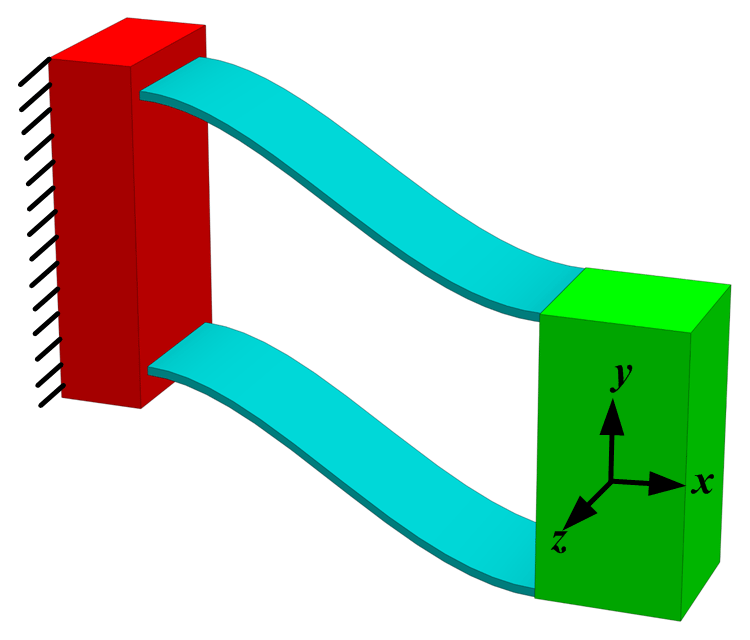
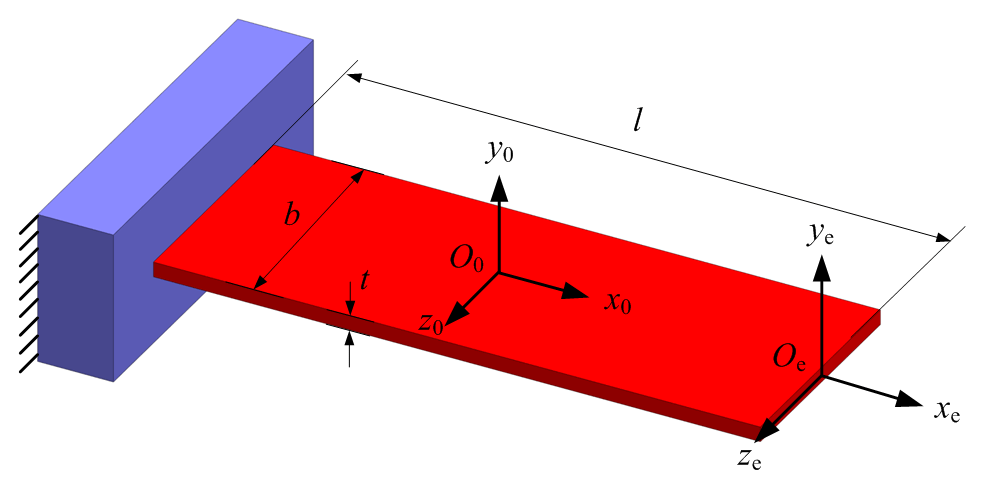
Parallel leaf springs (PLSs) provide an approximate straight motion over relatively short strokes. As shown in Fig. 1, PLSs have 1 compliant degree of freedom (DOF) in the drive direction y. In the other two translational directions, x and z, and in the rotational directions, Rx, Ry, and Rz, the support stiffness are several orders of magnitude higher than that in the drive direction. The material is assumed to be linear elastic in this paper. Since the pioneering work of Bernoulli and Euler, many related studies have been published for a single beam (e.g., Timoshenko, 1922; Awtar and Sen, 2010; Meijaard, 1996). Much work has also been done by Awtar et al. (2007) and Howell (2001) on parallel leaf springs.
A parallel leaf-spring carrying mechanism (PLCM) is considered to be a parallel mechanism. Investigation of the compliance and stiffness of parallel mechanisms can be dated back to the study of elastically suspended robotic systems (Patterson and Lipkin, 1993). More recently, a vibratory bowl feeder was modeled as a parallel mechanism with leaf-spring compliance legs (Dai and Ding, 2006; Ding and Dai, 2008), and a compliance device was built using parallel slender beams in remote-center compliance (Ciblak and Lipkin, 2003). Other methods of modeling compliant mechanisms include finite-element-based approaches (Pashkevich et al., 2009; Klimchik et al., 2013), and these approaches have been used to model the complex shapes of elastic limbs, which is usually straightforward and computationally affordable. In terms of the simple shape of limbs, such as slender beams and blades, analytical models like the Euler–Bernoulli model or the Timoshenko model are computationally efficient and can be used to reveal the intrinsic characteristics of a compliant mechanism.
The position and orientation accuracy of a compliant carrying mechanism is an important performance index. The geometric error of a rigid connector influences the terminal trajectory and equilibrium pose. Much work has been done on the influence of uncontrollable factors, such as the geometric error, the clearance, and the assembly error. For example, Meijaard et al. (2010) analyzed the consequences of static and dynamic misalignments in a parallel leaf-spring mechanism; Luo et al. (2015) analyzed the influence of parasitic displacement and connector deflection on lumped and distributed compliant parallel-guiding mechanisms; Ding and Dai (2008) considered the mass and the hysteresis damping of flexible members and proposed a complete model for a vibratory bowl feeder; and Ropponen and Arai (1995) considered the hinge position error, the driving error, and the clearance of a kinematic joint and proposed an attitude calculation model for a Stewart platform.
On the basis of predecessors' work, a new problem has arisen: the geometric error of a flexible arm, including the height and the top plane's direction in the parallel compliant mechanism, causes the attitude of the carrier (wafer) to change after handover. This issue requires the innovative use of the compliance matrix method combined with spatial balance and geometric constraints to establish an attitude calculation model in order to achieve an accurate solution for the spatial flexible support wafer attitude change in the parallel compliance mechanism. Therefore, the analytical model of a novel parallel leaf-spring carrying mechanism is investigated in this paper. Moreover, the geometric errors of a flexible arm are considered, and the equilibrium attitude is calculated. The influence of the equilibrium attitude at different heights and the initial tilts of top planes are also analyzed separately. In addition, attitude measurement experiments of wafer exchange are used to verify the analytical model and attitude calculation.
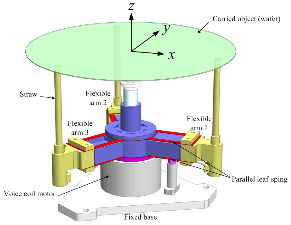
As shown in Fig. 2, a PLCM consists of a fixed base, a voice coil motor, three flexible arms, an aerostatic slideway, and a carried object (wafer). Each flexible arm is formed by two PLSs and rigid connections (straws). PLCMs can realize flexible loading and unloading as well as stable and gentle carrying. A PLCM is applied to situations that required fast, stable, and accurate transport of the carried object, such as lithography.
The slideway uses an air-bearing structure, and the moving distance of slideway is small, which can effectively reduce the inclination and the offset of the overall movement. Through high-precision machining and assembly, for example, there are very high requirements for the verticality and straightness of the slideway, and its influence on the attitude after exchange is very small and can be ignored. In addition, the initial position of the carried object is detected using an approach such as edge detection, and adjusting the corresponding position can ensure accuracy below the micrometer level, so that the object is in a relatively perfect position after exchange.
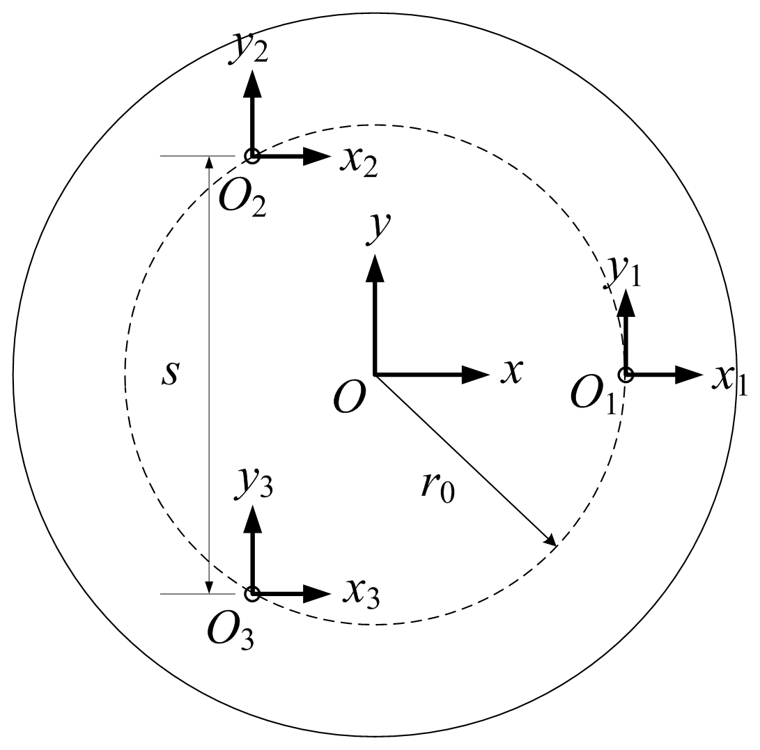
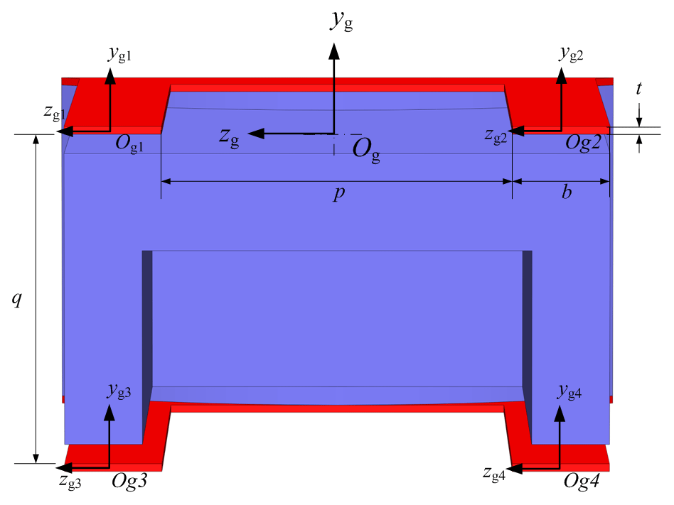
Each flexible arm has the drive direction z where the compliance is high, whereas the other translation directions, x and y, where the compliance is low, and the rotation directions, Ry and Rx, have suitable compliance to complete the flexible loading and unloading. The angle between two flexible arms is 120∘, as shown in Fig. 3. As shown in Fig. 4, the global coordinate frame is established at the center of the carried object, and the ith arm coordinate frame can be established at the top of the ith flexible arm. The parallel leaf-spring set coordinate frame is established at the end of parallel leaf spring set, as shown in Fig. 5.

A PLCM is equivalent to a compliant mechanism. The major components are three flexible arms. Each arm consists of two parallel leaf springs. A 6-DOF compliance matrix is introduced for the leaf spring. Each leaf spring can be described as a beam. This combines bending, extension, and torsion. A small deflection of the leaf spring can be considered as a deflection screw in the axis coordinates.
where δ(x)={δxδyδz}T represents the three translational deflection elements along the corresponding axes in the local coordinate frame shown in Fig. 6. θ(x)={θxθyθz}T gives the three rotational deflection elements about the corresponding axes of the local coordinate frame. According to the Euler–Bernoulli model, the leaf-spring compliance matrix can be given in axis coordinates as shown below.
Here, the beam is assumed to have constant rectangular cross section and length l. The shear effect is ignored. Moments of inertia Iy and Iz are given as and , the torsion constant Ix is given by Roark et al. (1976), G is the shear modulus, and E is the elastic modulus.
Coordinate frame is located at the end of a leaf spring. When external wrench is applied at the free end of a leaf spring, deflection twist T is generated depending on the integrated compliance Ce. According to the screw theory, the relationship between Ce and Co can be written as follows:
where Ade is the adjoint transformation matrix between the local coordinate frame and the global coordinate frame .
Re is the coordinate rotation matrix, which is a 3×3 unit matrix, and Pe is the antisymmetric matrix of the coordinate translation vector.
As shown in Fig. 5, two parallel leaf springs constitute a parallel leaf-spring set. According to the screw theory, the compliance matrix of the ith leaf spring in the global coordinate frame Og and the corresponding adjoint mapping can be given by
Rgi is a 3×3 unit matrix, and Pgi is the antisymmetric matrix of the ith leaf spring. The latter represents a coordinate translation vector and can be given by
The PLS set consists of four leaf springs in parallel. Thus, the relationship between Cg and Cgi can be written as follows:
When the flexible arms carry an object like a wafer, forces and torques may occur to make the end of the arm deviate from the ideal position and orientation; these deviations are related to static compliance (stiffness). Therefore, the static compliance is used to calculate the equilibrium attitude of the carried object.
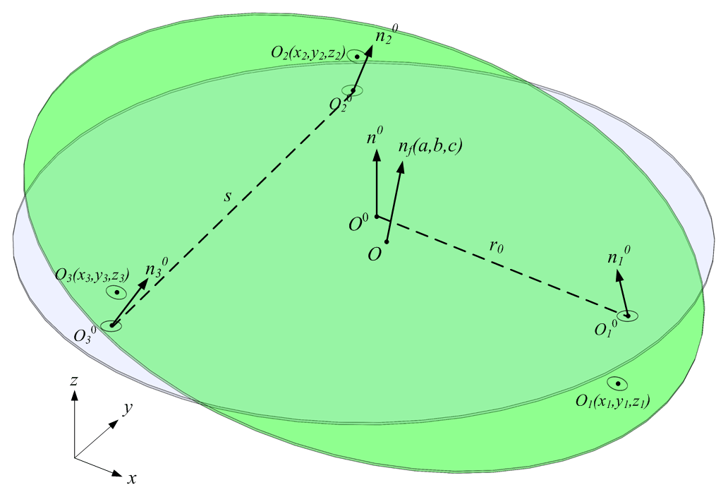
The attitude changes in the PLCM are small under normal operating conditions, comprising only small translation and rotation. Considering the geometric errors of a flexible arm, including length variation and direction variation of the top plane, the equilibrium attitude calculation of the carried object is modeled using the displacement method in order to analyze the influence of geometric errors. As shown in Fig. 7, global coordinate frame is established at the center of the carried object, and local coordinate frame , where i=1, 2, 3, is established at the top center of ith flexible arm. The unknown variables are the direction vector and the coordinate () of the top center of the ith flexible arm at equilibrium.
4.1 Displacement and rotation of the flexible arms' top planes
For stiffness matrix K1 of flexible arm 1 in coordinate frame , the relationship between the compliance of a parallel leaf-spring set and the stiffness matrix K1 can be given by
Here, . Translation P1 is completed by shifting the coordinate along axis x by d and then along axis y by h.
The center points of the top planes O1,O2, and O3 are located in plane xoy. They are uniformly distributed in a circle with radius r0. Arm 2 is in the same arrangement but rotated about axis z by α. In coordinate frame , stiffness matrix K2 can be given as follows:
Transformation matrix T can be given as follows:
In the same way, stiffness matrix K2 in coordinate frame can be given by
The following is an analysis of the displacement and rotation of the flexible arms' top planes. Local coordinate frame can follow the translation and rotation of the ith top plane. Translation δi can be given by
where is the initial coordinate of point Oi; this value can actually be measured.
The rotation of the local coordinate frame expresses the rotation of the ith top plane. The initial normal vector of the ith top plane is and can actually be measured. After rotation, the normal vector of the carried object is . According to Rodrigues formula, the rotation matrix can be given by
For a small rotation angle, , cos θi≈1, sin θi≈θi. Simplifying the above equation yields
Thus, a small rotation angle θi around axis ωi equals small rotation transformations ξxi,ξyi, and ξzi. According to Eqs. (13) and (14), rotation ξi can be given by
rotation about axis ωi can be given by
and rotation angle θi can be given by
4.2 Equilibrium attitude calculation
Equilibrium attitude calculation is used to calculate the carried object's attitude variation and the top planes' displacements after static equilibrium. Initial normal vector and initial coordinate ( of the center point of the ith top plane as well as the gravity of the carried object are known variables.
In the global coordinate frame , according to the stiffness of flexible arms and the attitude variations of top planes, the forces and couples between the carried object and each flexible arm can be obtained. The equilibriums of forces can be expressed as follows:
where Fxi, Fyi, and Fzi are the forces between the carried object and each respective flexible arm.
In the same way, the equilibriums of couples can be expressed as follows:
where is the coordinate of the center point of the ith top plane.
Based on the stiffness definition,
From equations above, the equilibrium Eq. (21) can be obtained using Eqs. (18) and (19).
Here, Q is the coefficient matrix.
The carried object is a rigid body, and the top planes are in a coplanar condition after the static equilibrium; the geometric constraint equations are given as Eqs. (23) and (24). Normal vector is a unit vector, and this relationship is given by Eq. (22).
Normal vector and coordinate of point Oi at equilibrium can be obtained by solving the nonlinear equation group. Thus, the attitude variation of the carried object caused by geometric errors can be calculated.
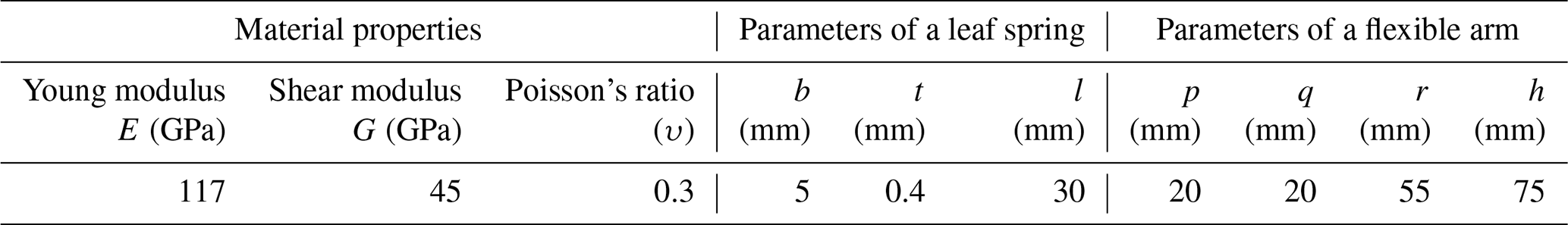
In this paper, the PLCM uses distributed leaf springs as flexible units. The leaf-spring material is beryllium copper alloy (C17200). It satisfies the four basic assumptions for deformable solids (continuity, homogeneity, isotropy, and low deformation). The PLCM generally completes the bearing and transportation of rigid objects with high precision and low mass. The attitude changes in the PLCM are small under normal operating conditions, comprising only small translation and rotation. The connecting pieces and the carried object are considered to be rigid bodies, and the weight of the connecting pieces is ignored. The physical parameters of the PLCM in its initial state are shown in Table 1.
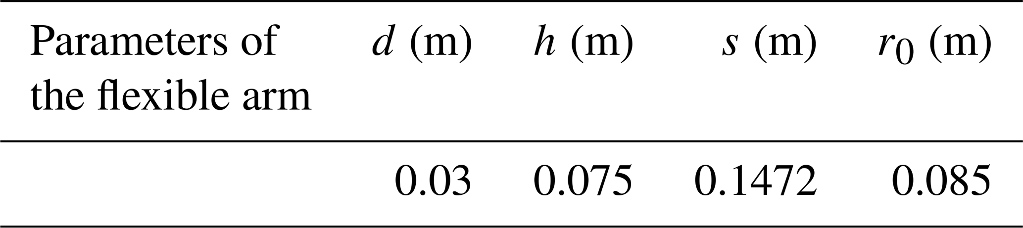
Considering the existence of geometric errors, the equilibrium attitude of the carried object can be calculated using the displacement method. The geometric parameters of the PLCM are shown in Table 2.
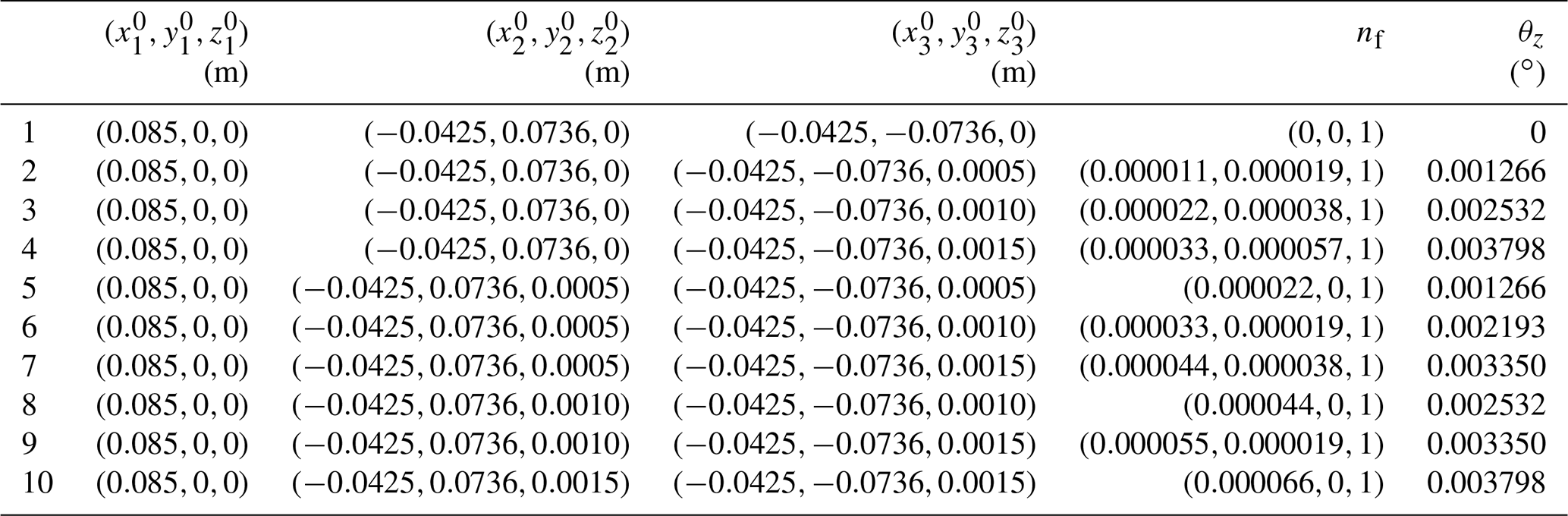
5.1 Height variations in the three flexible arms
The attitude variations cover a small scope, and the mass center of the carried object is at the origin of the global coordinate O. The three top planes of the flexible arms are uniformly distributed in a circle with radius r0. The initial normal vectors are . The height variation range is 0–0.0015 m. Calculating 10 different groups, the results consist of normal vector as well as angle θz between normal vector nf and the positive axis z, which are shown in Table 3.
As shown in Table 3, groups 4 and 10 have the same two initial heights of the same two arms, whereas the other is different; as a result, they have the same angle θz but different directions of the normal vector nf. Similar phenomena occur between groups 3 and 8 and between groups 2 and 5. In groups 7 and 9, the first arm axis z initial values are 0 and 0.0015 m, whereas the second arm values are 0.0005 and 0.0010 m; they have the same angle θz but different directions. The reason for this is that the three top planes of the arms are uniformly distributed in a circle, and the plane that goes through the initial center points of the three top planes has the same angle as the z axis but different directions.
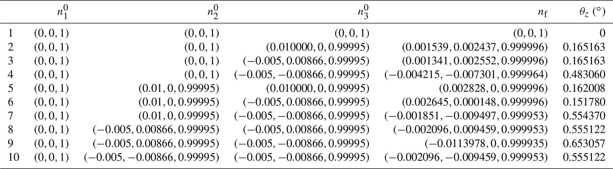
5.2 Direction variations of the top planes of the three flexible arms
The initial coordinates of the top planes' center points are (0.085, 0, 0), (−0.0425, 0.0736, 0), and (−0.0425, −0.0736, 0). The initial normal vectors of the top planes, , are changed in each group, and there are four cases: (0, 0, 1), (0.01, 0, 0.99995), (−0.005, 0.00866, 0.99995), and (−0.005, −0.00866, 0.99995). Calculating 10 different groups, the results consist of the normal vector as well as the angle θz between nf and the z axis, as shown in Table 4.
It can be found from Table 4 that the direction variation impact is larger than the height variation impact. The first group only shows translation in the z direction. Group 9 has the largest θz in Table 4, as the initial directions of tilt are separate along the length direction of the leaf spring. It can be seen that groups 2 and 3 have same two initial angles between and axis z but different directions; as a result, they have the same angle θz but different directions of the normal vector nf. Arms 2 and 3 of groups 8 and 10 have the same initial angles between and the z axis but different directions, and the three arms are circularly symmetric; thus, they have the same angle θz but different directions of the normal vector nf.
The three top planes realize a coplanar condition when equilibrium is established, and each top plane has a different translation and rotation. It can be seen from analysis that the normal vector nf of the carried object relates to the initial tilts of the normal vectors of the top planes. As shown in Fig. 4, the compliance of a single flexible arm in direction Ry is relatively large, so the initial tilt in direction Ry has a great influence on the normal vector nf. Thus, the compliance of a single flexible arm in direction Rx is relatively small, so the initial tilt in direction Rx has little influence on the normal vector nf.
As shown in Figs. 8 and 9, an experimental wafer exchange system was established. The attitude measurement of the wafer exchange is the main purpose of this system, which is used for the validation of the attitude calculation model. The system includes the following parts: the PLCM, a sensing module, a vacuum adsorption module, a moving module, a signal-collecting module, and a computer.
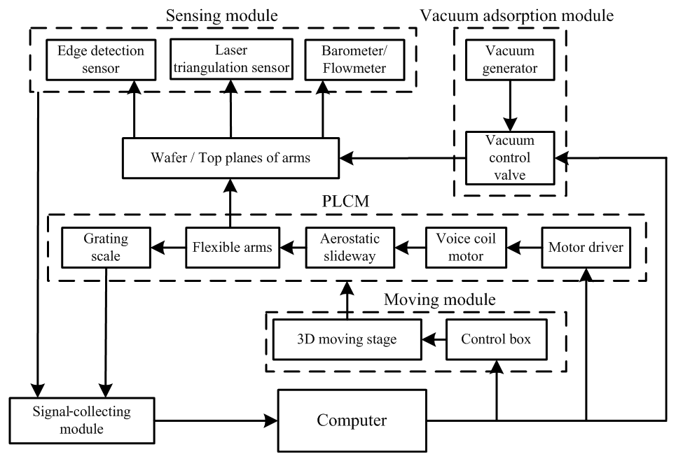
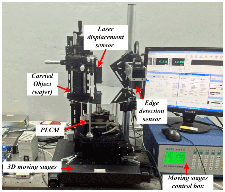
The sensing module is divided into three parts: z-direction displacement detection, wafer edge detection, and vacuum pressure detection. It mainly measures the attitudes of the wafer and the top planes of the arms. Laser triangulation displacement measurement is used, which (combined with the 3D moving stages) constitutes a 3D coordinate measurement system. The laser displacement sensor is a LK-G30 sensor (KEYENCE) that has a 0.01 µm repeat accuracy and a ±5 mm measurement range. The 3D moving stages are the xy axis moving stages and the Rz rotary stage (BOCIC), which have a respective 0.1 µm and 1.4 µrad resolution and a respective 3 µm and 9.7 µrad positioning accuracy. Wafer edge detection selects a racer linear array charge-coupled device (CCD) with a pixel size of 7 µm, an 8 bit output, and 1024 or 2048 units corresponding to a frequency of 18.35 or 9.42 kHz, respectively (BASLER). The position and orientation of the top planes were measured and fitted using the planar fit method without loading the carried object (Li et al., 2016).
The attitude measurement of wafer exchange includes three main processes: the attitude measurement of the three top planes of the PLCM arms, the wafer exchange, and the wafer exchange attitude measurement. There are three sets of PLCMs for the wafer exchange experiment. The results of the attitude measurement of the three top planes are given in Table 5. The wafer exchange process is that the moving part of the mechanism (slider mover and three flexible arms) proceeds to the handover position. The tops of the flexible arms then use vacuum to absorb the wafer. After reaching the vacuum threshold, the moving part continues to rise to the fixed position. Finally, the wafer is brought down to the specified position of the lithography workpiece table, and the vacuum adsorption is removed to complete the wafer exchange. The control program of the motion part adopts the deadbeat control with constraint and no ripple method (Li et al., 2015).

Table 6Results of the attitude calculation and attitude measurement.
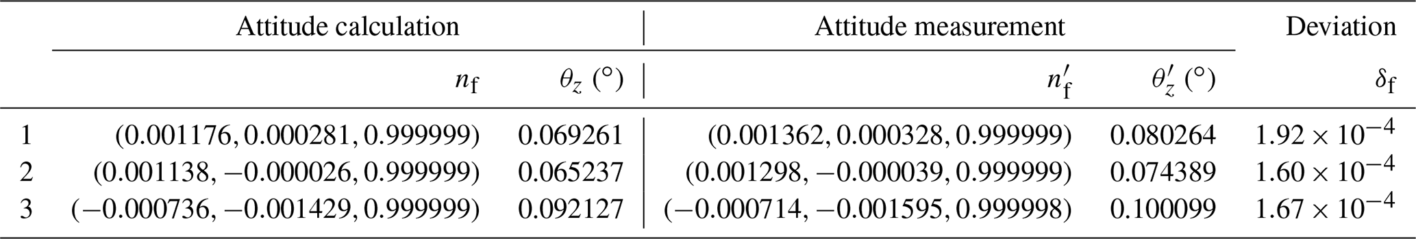
With respect to exchanging the wafer and loading the carried object, the results of the attitude calculation and attitude measurement are given in Table 6, which includes the normal vector of the carried object as well as the angle θz between the normal vector nf and the positive z axis. The deviation δf of the normal vector nf of the attitude calculation and the normal vector of attitude measurement can be given by
It can be seen from Tables 5 and 6 that both the position and orientation of top planes can cause a different equilibrium attitude of the carried object. Different combinations of the position and orientation of the three top planes change the directions of the equilibrium attitude of the carried object. For example, it can be seen from Table 6 that group 1 is located in the first quadrant, group 2 is located in the fourth quadrant, and group 3 is located in the third quadrant. The normal vectors of the attitude calculation and attitude measurement are located in the same quadrant; they are very close, and the angles between the normal vector and the positive z axis are also very close. The deviations δf of the normal vector between calculation results nf and measurement results are for group 1, for group 2 and for group 3, which are small enough to satisfy practical requirements. The effectiveness of the attitude calculation model is illustrated by experimental verification. Using the Euler–Bernoulli model, which ignores shear deformation and rotary inertia, makes calculation result relatively small. Measurement error may be another reason for the deviations.
This paper presents a comprehensive study of a new parallel leaf-spring carrying mechanism, covering analytical modeling to attitude calculation, and provides a better understanding of the characteristics of PLCMs. With respect to the analytical modeling, this paper establishes a compliance matrix of the parallel leaf-spring set. Regarding the attitude calculation, the respective carried object eccentricity and geometric errors of the flexible arm are considered, and the displacement method is used to calculate the equilibrium attitude. Moreover, the laser triangulation coordinate method is used to carry out the attitude measurement. The effectiveness of the attitude calculation model is illustrated by numerical analysis and experimental verification. The proposed methods to address the mobility characteristic analysis and attitude calculation are not only available for PLCM but also for complex parallel compliant mechanisms.
All of the data used in this paper can be obtained upon request from the corresponding author.
PL conceived of the presented idea and carried out the experiments. PL and ZRT undertook the numerical analysis and wrote the paper. WHZ checked the article and made suggestions.
The contact author has declared that neither they nor their co-authors have any competing interests.
Publisher's note: Copernicus Publications remains neutral with regard to jurisdictional claims in published maps and institutional affiliations.
This research has been supported by the National Natural Science Foundation of China (grant no. 62003237), the Tianjin Enterprise Technology Commissioner Project (grant no. 20YDTPJC01700), and the State Key Laboratory of applied optics (grant no. SKLA02020001A02).
This paper was edited by Daniel Condurache and reviewed by Zhixuan Cao and Petr Chalupa.
Awtar, S. and Sen, S.: A generalized constraint model for two-dimensional beam flexures: nonlinear load-displacement formulation, J. Mech. Design, 132, 081008, https://doi.org/10.1115/1.4002005, 2010.
Awtar, S., Slocum, A. H., and Sevincer, E.: Characteristics of beam-based flexure modules, J. Mech. Design, 129, 625–639, https://doi.org/10.1115/1.2717231, 2007.
Ciblak, N. and Lipkin, H.: Design and analysis of remote center of compliance structures, J. Robotic Syst., 20, 415–427, https://doi.org/10.1002/rob.10096, 2003.
Dai, J. S. and Ding, X.: Compliance analysis of a three-legged rigidly-connected platform device, J. Mech. Design, 128, 755–764, https://doi.org/10.1115/1.2202141, 2006.
Ding, X. and Dai, J. S.: Characteristic equation-based dynamics analysis of vibratory bowl feeders with three spatial compliant legs, IEEE T. Autom. Sci. Eng., 5, 164–175, https://doi.org/10.1109/tase.2007.910301, 2008.
Howell, L. L.: Compliant mechanisms, John Wiley & Sons, https://doi.org/10.1007/978-1-4471-4510-3_7, 2001.
Klimchik, A., Pashkevich, A., and Chablat, D.: CAD-based approach for identification of elasto-static parameters of robotic manipulators, Finite Elem. Anal. Des., 75, 19–30, https://doi.org/10.1016/j.finel.2013.06.008, 2013.
Li, P., Cui, J. W., Tan, J. B., and Ding, X. M.: Application of Deadbeat Control with Constraint and Non-ripple in Precision Rapid Displacement System, Ninth International Symposium on Precision Engineering Measurement and Instrumentation, 9446, 649–655, https://doi.org/10.1117/12.2181184, 2015.
Li, P., Ding, X. M., Tan, J. B., and Cui, J. W.: A hybrid method based on reduced constraint region and convex-hull edge for flatness error evaluation, Precis. Eng., 45, 168–175, https://doi.org/10.1016/j.precisioneng.2016.02.008, 2016.
Luo, Y., Liu, W., and Wu, L.: Analysis of the displacement of lumped compliant parallel-guiding mechanism considering parasitic rotation and deflection on the guiding plate and rigid beams, Mech. Mach. Theory, 91, 50–68, https://doi.org/10.1016/j.mechmachtheory.2015.04.007, 2015.
Meijaard, J. P.: Validation of flexible beam elements in dynamics programs, Nonlinear Dynam., 9, 21–36, https://doi.org/10.1007/bf01833291, 1996.
Meijaard, J. P., Brouwer, D. M., and Jonker, J. B.: Analytical and experimental investigation of a parallel leaf spring guidance, Multibody Syst. Dyn., 23, 77–97, https://doi.org/10.1007/s11044-009-9172-4, 2010.
Pashkevich, A., Chablat, D., and Wenger P.: Stiffness analysis of overconstrained parallel manipulators, Mech. Mach. Theory, 44, 966–982, https://doi.org/10.1016/j.mechmachtheory.2008.05.017, 2009.
Patterson, T. and Lipkin, H.: Structure of robot compliance, J. Mech. Design, 115, 576–580, https://doi.org/10.1115/1.2919228, 1993.
Roark, R. J., Young, W. C., and Plunkett, R.: Formulas for Stress and Strain, J.ASME, 43, 522, https://doi.org/10.1115/1.3423917, 1976.
Ropponen, T. and Arai, T.: Accuracy analysis of a modified Stewart platform manipulator, IEEE Int. Conf. Robot., 1, 521–525, https://doi.org/10.1109/robot.1995.525336, 1995.
Smith, S. T.: Flexures: elements of elastic mechanisms, 1st Edn., CRC Press, London, https://doi.org/10.1201/9781482282962, 2000.
Smith, S. T. and Chetwynd, D. G.: Foundations of ultra-precision mechanism design, 1st Edn., CRC Press, London, https://doi.org/10.1201/9781315272603, 2017.
Timoshenko S.: On the torsion of a prism, one of the cross-sections of which remains plane, P. Lond. Math. Soc., 2, 389–397, https://doi.org/10.1112/plms/s2-20.1.389, 1922.
Yuanqiang, L. and Wangyu, L.: Analysis of the displacement of distributed compliant parallel-guiding mechanism considering parasitic rotation and deflection on the guiding plate, Mech. Mach. Theory, 80, 151–165, https://doi.org/10.1016/j.mechmachtheory.2014.06.005, 2014.
- Abstract
- Introduction
- Description of structure
- Generation of compliance matrix
- Attitude calculation
- Numerical analysis of the attitude calculation model
- Experimental verification of the attitude calculation
- Conclusion
- Data availability
- Author contributions
- Competing interests
- Disclaimer
- Financial support
- Review statement
- References