the Creative Commons Attribution 4.0 License.
the Creative Commons Attribution 4.0 License.
 | 04 Feb 2021
Optimal design and experimental study of fixed abrasive pads based on coupling of damping regulation and pellet arrangement
Chaoqun Xu
Congfu Fang
Yuan Li
Chong Liu
Lapping and polishing technology is an efficient processing method for wafer planarization processing. The structure of the fixed abrasive pad (FAP) is one of the most concerning issues in the research. The FAP structure affects the pressure distribution on the wafer surface, and the pressure distribution during processing has a significant influence on the wafer surface. Therefore, in this paper, a better pressure distribution is obtained by adjusting the angle of the spiral arrangement and the damping distribution of the damping layer of the FAP, thereby obtaining better processing quality. Based on the above theory, a new type of FAP, with coupling between the arrangement of the pellets and the damping regulation of the damping layer, was designed and optimized. The machining effects of different FAPs on the workpiece surface are compared in terms of material removal rate, material removal thickness, and surface roughness. The test results show that the workpiece material removal rate is higher than that of the traditional FAP when using the optimized FAP. The non-uniformity of the optimized FAP for that of material removal was 4.034 µm, which was lower than the traditional FAPs by 24.4 % and 17.6 %, respectively. The average surface roughness, Ra, of the optimized FAP is 0.21 µm, which is lower than 19.1 % and 12.5 % of the two traditional FAPs, respectively. Therefore, workpiece material removal and distribution are more uniform, and the surface quality of the workpiece is better when the optimized FAP processing is used. The test results prove that the optimized pellet arrangement and damping can achieve a better surface quality of the workpiece, which can meet the precision lapping process requirements for high-quality surfaces and large-scale production of brittle and hard materials such as sapphire.
- Article
(3000 KB) - Full-text XML
- BibTeX
- EndNote


Currently, the most common substrate for gallium nitride (GaN) growth is sapphire. Sapphire has stable chemical properties, and the quality of the processed device is better (Zhang et al., 2019; Fang et al., 2017, 2019; Sokol et al., 2013) As substrate geometries are still shrinking, lithographic accuracy requirements are becoming higher and higher. In order to improve the accuracy of lithography, a shorter wavelength of light needs to be selected, but the focal depth is reduced accordingly. When the unevenness of the lithographic surface is uneven, there will be problems such as poor exposure or even no exposure. Therefore, it is required that the unevenness of the lithographic surface should be reduced to the focal depth range, i.e., to achieve a high level of surface flatness (Liang et al., 2012; Arunachalam et al., 2015; Tam et al., 2007; Li, 2010). Some scholars have proposed the use of a fixed abrasive pad (FAP) for processing. Due to the uniform distribution of the abrasive particles in the surface of the FAP and the controllable movement of the abrasive particles, the surface quality of the workpiece is good (Dong et al., 2014; Fang et al., 2018; Qiu et al., 2012).
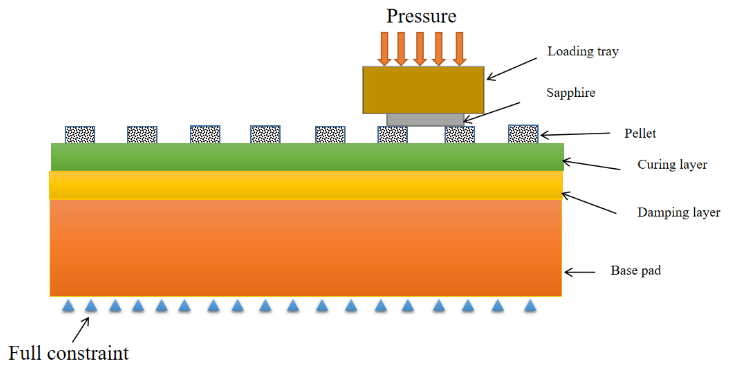
Figure 1Contact mechanical model of the wafer and the surface of the fixed abrasive pad (FAP).
However, the use of FAPs can improve machining efficiency, but there is severe wear of the FAP and surface damage to the workpiece. To overcome these problems, some scholars have realized that the precise lapping of brittle and hard materials, such as sapphire, from the perspective of regulating the surface pressure distribution of the workpiece during process is needed.
According to the Preston equation, in the process of lapping and polishing, the material removal of the workpiece is the micro-cutting process of a large number of abrasive particles on the surface of the workpiece under a certain pressure. Regulating the pressure distribution between the abrasive particles and the workpiece has a great impact on the processing quality. So many scholars have considered the research on the removal mechanism of the lapping and polishing process from the perspective of the pressure field between the workpiece and the FAP. Yang et al. (2015) believe that higher contact pressure results in a larger contact area, and higher sliding speed or contact pressure will lead to a higher wear rate of diamond grits (Yang et al., 2015). Lv et al. (2011) established a static model of a contact pressure field which optimized the parameters of the sunflower pad structure. Considering the elastic modulus and Poisson's ratio of the base pad, the appropriate uniformity of the pressure distribution can be improved (Lv et al., 2011). Liu (2006) used the same polishing conditions for the two polishing pads to polish workpieces separately. It was concluded that the greater the pressure and the higher the speed, the more obvious the advantage of the abrasive polishing pad, but it did not specifically consider the contact with the pressure of the indenter (Liu, 2006). Rao (2014) installed microelectromechanical systems (MEMS) wireless vibration sensors at different radial positions of the wafer carrier near the substrate and concluded that the structure of the polishing pad has a pronounced influence on the morphology of the wafer surface (Rao, 2014). Zha (1984) analyzed the polishing process of optical parts in detail, and they set up a mathematical model of the pressure distribution in the contact area between the lapping pad and the workpiece (Zha, 1984). Kang and Hadfield (2005) performed a fixed abrasive lapping test on Si3N4 ceramic bearing rollers and analyzed the effects of pressure and lapping fluid on the material removal rate (MRR). Belkhir et al. (2013) obtained the coefficient of friction by measuring the pressure distribution in the contact area. The change in contact pressure is the primary factor that causes the glass surface quality to change (Belkhir et al., 2013). Zhang et al. (2004) established a mathematical model of the pressure distribution in the contact area, based on the arrangement of diamond pellets, and studied the impact of wafer size and processing parameters on the pressure distribution (Zhang et al., 2004).
Although a large number of scholars have carried out speed and pressure research based on the Preston equation, they mainly focus on the design of the surface structure of the pad. In fact, the influence of the base pad structure on the processing pressure is also very large. Therefore, this paper designs a new type of FAP, from the optimization of the surface structure and control of damping layer of the base pad, and performs experimental processing. It compares our model with the traditional FAP and tests the angles of MRR and workpiece surface quality.

2.1 Contact mechanics modeling
The structure of the polishing pad is primarily composed of pellets, a curing layer, a damping layer, and a base pad. The surface of the FAP is layered into two layers, where the upper layer is the curing layer, mainly for curing the resin pellets, and the lower layer is the damping layer. The lower layer is mainly used to adjust the surface damping distribution. Both layers are made of photo-curable resin. The contact mechanical model of the wafer and the surface of the FAP is shown in Fig. 1.
According to the basic mechanical equation of contact mechanics, the stress relationship at the contact interface between the wafer and the loading tray is shown in Eq. (1) as follows:
according to the basic equilibrium equations of contact mechanics. σza(r,z), σra(r,z), and τrza(r,z) are axial stress, radial stress, and shear stress on the surface of the loading tray, respectively. σzb(r,z), σrb(r,z), and τrzb(r,z) are axial stress, radial stress, and shear stress on the contact surface of workpiece, respectively. Similarly, the stress relationship at the contact interface between the wafer and the FAP is shown in Eq. (2) as follows:
The contact pressure on the workpiece surface is as follows:
Among them, σzc(r,z), σrc(r,z), and τrzc(r,z) are axial stress, radial stress, and shear stress on the contact surface of the FAP, respectively. σzd(r,z), σrd(r,z), and τrzd(r,z) are axial stress, radial stress, and shear stress on the contact surface of the workpiece, respectively.

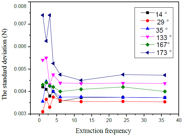
Figure 4The standard deviation of the surface of the FAP at different extraction frequencies.
2.2 Establish the element type and material parameters
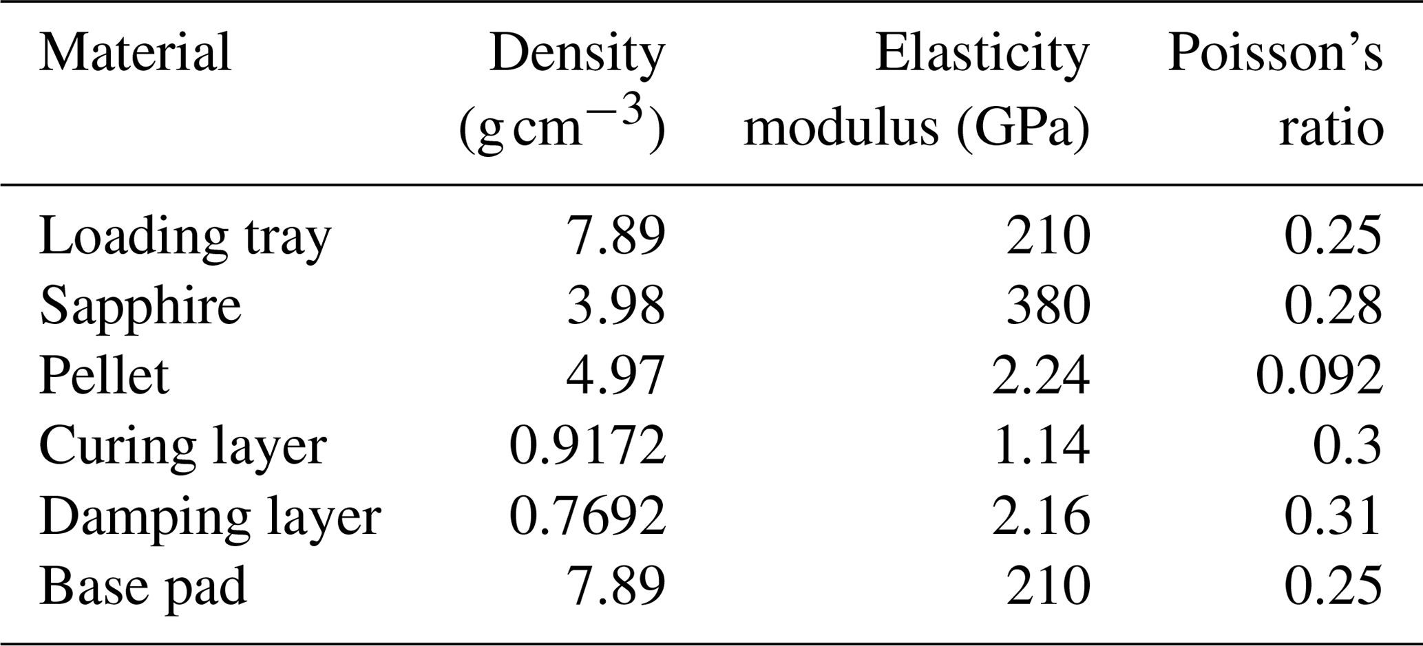
We preferentially select a SOLID185 unit for meshing. The meshing diagram is presented in Fig. 2. In order to ensure a more uniform distribution of the nodes, the resulting stress distribution is more accurate. The mesh shape of the workpiece surface is a tetrahedron, and the pellet is automatically meshed. Material parameter settings are given in Table 1.
2.3 Contact analysis
The contact involved in this model is the contact between the workpiece and the pellet. The type of contact is frictional contact. Generally, the target surface and the contact surface are selected by the principle that the larger surface is the contact surface, and the smaller surface is the target surface. When pellets are arranged on the surface of the FAP, there is a certain gap in the surface. The area of the contact area is smaller than the wafer because the hardness of the pellet is greater than that of the wafer. We choose the surface of the wafer as the contact surface and the surface of the FAP as the target surface. We set the coefficient of friction to 0.2 and used Lagrange's equation to solve it. Through the contact process, the contact between the FAP and the wafer is very complicated because it includes the effect of polishing fluid, cooling fluid, and actual lapping and polishing errors. Thus, we need to make the following assumptions about the contact of the two materials:
- 1.
The flexible body is in contact with the flexible body, without considering the influence of polishing liquid and cooling liquid.
- 2.
The surface of the substrate layer pellets is flat, but there are corresponding friction coefficients.
- 3.
The materials are the same materials in this process.
- 4.
There is an iterative analysis of the pressure at each moment, which can be regarded as a steady-state pressure analysis.

2.4 Boundary constraints imposed
In the actual polishing process, a certain uniform surface load is applied on top of the loading tray. The FAP is fixed below the wafer. The loading tray and the wafer only move in an axial direction. Therefore, the nodes on the bottom surface of the FAP need to be applied with x, y, and z. With the constraint on the direction, the body formed by the bonding of the loading tray and the wafer needs to be bound in the x and y directions. Since the load applied is 2 kg and the wafer size is 50.8 mm, the surface load applied by the loading tray to the workpiece surface is 9.87 kPa. The formula for this calculation is as follows:


2.5 Evaluation method
In order to quantitatively evaluate the pressure distribution results, an evaluation method for the pressure uniformity is introduced, which is similar to the trajectory uniformity evaluation method, and it grids the pressure data values of all nodes and evaluates the surface pressure distribution of the workpiece through the non-uniformity of pressure (NUP).
In the formula, represents the average stress in the ith grid on the workpiece surface, represents the average stress value of all grid regions, and N represents the number of square grids on the workpiece surface. The smaller the NUP, the more uniform the demonstration of the pressure distribution on the workpiece surface.
3.1 Surface structure design
In recent years, bionics has become a hot topic, and it is a science that combines certain phenomena and laws of nature, which many scholars are applying to the field of engineering science. For example, bionic aircraft which have been designed by simulating the movement of insects. The bionic super-hydrophobic nanomaterials have been developed on the surface of the hydrophobic properties. In nature, plants have evolved continuously in order to meet the needs of various conditions (Liu, 2010; Pan, 2015). They have formed special macro- and micro-structures, for example, sunflowers and other common plants. As shown in Fig. 3, in order to ensure a uniform structure of light and the flow of liquid, the grain structure is applied to the field of lapping and polishing through this common phenomenon. From the perspective of the processing field, the temperature field, the uniform distribution of the flow field, pressure field, and trajectory field have been studied by many scholars with regards to the structure of sunflower seeds.
Among them, the earliest arrangement of sunflower seed structure was proposed by Vogel (1979), which satisfies the distribution rule shown in Eq. (7). Thus, the arrangement of the pellets is based on the sunflower seed model proposed by Vogel (1979).
Among them, rn and θn, respectively, indicate the polar radius and polar angle of the nth pellet. The position of the nth pellet can be determined by the polar radius and polar angle, and c and α are the density parameter and the angle parameter of the pellet, respectively. The angle is the angle between the (n−1)th and nth pellet, c determines the arrangement density of the pellet, and α determines the arrangement shape of the pellet. In the simulation, the diameter of the FAP is 300 mm, the diameter of the pellets is 8 mm, the density of the pellet is c = 6 grain mm−2, and the number of pellets is 600.
The contact surfaces of the workpiece and the FAP at different times, including the contact area and the contact position vector, are different. The stress distribution on the workpiece surface is also different at different times. Therefore, a steady-state pressure field needs to be established to characterize the stress distribution on the surface of the workpiece.
Assume that the stress distribution of the workpiece surface at a certain time is Pi, then change the coordinate axis centered on the FAP, take the workpiece to rotate around the FAP as a cycle, set the angle of the workpiece around the FAP to β, and divide the workpiece evenly around the FAP surface once. For N, there are different extraction frequencies; for example, when β = 180∘, the proposed frequency is N=2, when β = 90∘, the extracted frequency is N=4, and when β = 60∘, the proposed frequency is N=6. For a moment, the stress distribution of a node position vector is calculated as P (x,y), and then the average stress distribution of this node corresponding to multiple moments is as follows:
For the entire FAP surface, when the extraction frequency is N, the average stress distribution on the workpiece surface is obtained, and the standard deviation of the average stress distribution on the workpiece surface is obtained as follows:
According to the definition of a standard deviation, it represents the degree of dispersion between different data. When the standard deviation is smaller, the degree of dispersion is also lower for the data, indicating that the pressure distribution on the surface of the workpiece is at a steady state. Based on this, the standard deviation of the surface of the FAP at N different time is obtained as shown in Fig. 4.
It can be seen from Fig. 4 that, when the effective extraction frequency changes from 1 to 6, the standard deviation changes greatly. When the effective extraction frequency is greater than 6, the standard deviation basically approaches the current level, indicating that the pressure distribution on the workpiece surface is stable. So, the pressure field simulation is performed when the extraction frequency is 6.
Figure 5 shows the simulation results of the FAP pressure (pressure unit – 10−2 MPa). It is found that the FAP with different structures has a great influence on the workpiece pressure. We quantitatively characterize the pressure distribution on the surface of the workpiece through the NUP, and the NUP values of different FAPs are shown in Table 2. The influence of the FAP on the magnitude of pressure change is 173∘ FAP > 133∘ FAP > 167∘ FAP > 35∘ FAP > 14∘ FAP > 29∘ FAP.
3.2 Damping layer structure
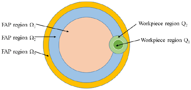
During the eccentric rotation of the workpiece around the FAP, the contact area of the surface of the FAP is different for the workpiece. The closer the workpiece is to the outer annular area, the larger the contact area. The contact area between the workpiece and the FAP is shown in Fig. 6. Different colors represent different areas. Q1 and Q2 are the inner area of the workpiece and the annular area of the outer ring of the workpiece, respectively. Ω1, Ω2, and Ω3 are the inner area, the middle annular area and the outer annular area of the FAP, respectively.
It can be seen from Fig. 6 that the relationship between the work area Q1 and the work area Q2 and the contact areas Ω1, Ω2, and Ω3 of the FAP surface is as follows:
Different annular areas of the workpiece corresponding to contact on the FAP area are not the same. There will also be a corresponding impact on the pressure distribution on the workpiece surface. The stress distribution on the workpiece surface can be changed by adjusting the damping size of the annular region of the FAP so that the pressure distribution on the workpiece surface can be better controlled and a better MRR distribution can be achieved.
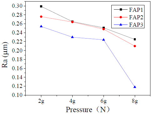
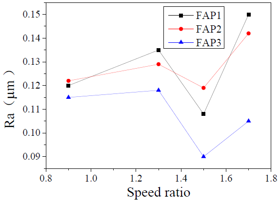
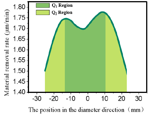
Figure 7 shows the 2D cut-off diagram. It can be observed from Fig. 7 that the MRR of the workpiece surface is higher near the middle, and the MRR is lower at the edge. Based on the Preston equation, when K is larger, then the contact normal pressure of the pellet on the workpiece surface is larger, and the MRR of the workpiece surface by the FAP is larger at this time. The two bands of peaks are roughly located at x = −15 and x = 10 mm. These two positions divide the FAP into three annular regions and adjust the damping to change the material removal rate. The main reason for this is that the workpiece is being processed under central pressure. If no damping adjustment is adopted, the material removal rate at the central position will be the highest. In order to make the material removal of the entire workpiece surface more uniform, the machining efficiency at the central position and edge position of the workpiece needs to be adjusted, so the method of the damping layer is adopted to design the FAP.
The material for the damping adjustment is formed by two different ratios of elastic varnishes through light curing. These two types of elastic varnishes are stain-resistant UV-MI-154 metal oil (hard oil) and stretchable UV-266N elastic varnish (soft oil) produced by Hangzhou Kewang Special Ink Co. Ltd. These two kinds of elastic varnishes can be cured quickly. By adjusting the different proportions of elastic varnishes, different damping layers are obtained. Different proportions of elastic varnishes are selected for deployment and are then cured by ultraviolet light. The material performance parameters of the oil were tested. The specific test methods are shown in the next section. The proportion of the two elastic varnishes, and the corresponding material performance parameters are shown in Table 3.
When mixing with different proportions of elastic varnishes, there is little difference in density. When the blending ratio is fixed to one, the elasticity modulus of the hard oil is smaller than that of the soft oil varnish. When the blending ratio is 1:1, the elasticity modulus is in the middle of the two, which is consistent with the characteristics of hard oil and soft oil.
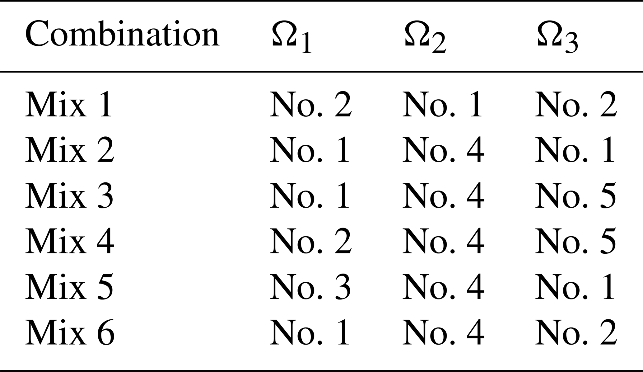
The eccentricity is 80 mm, the center of the lapping pad is used as the origin of the coordinates, and the three circular sections satisfy the polar radii of R1 (0; 65), R2 (65; 90), and R3 (90; 150), respectively. After mixing different proportions, we have formulated different combinations of elastic varnishes, as shown in Table 4.
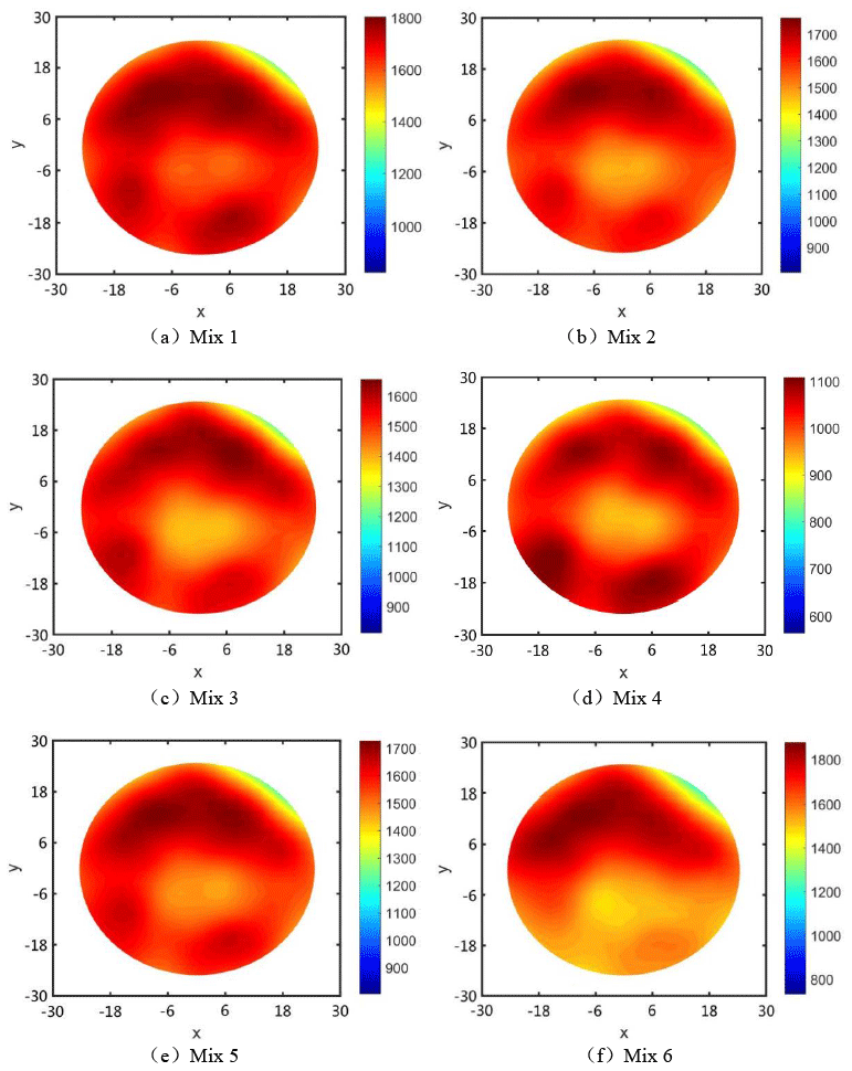
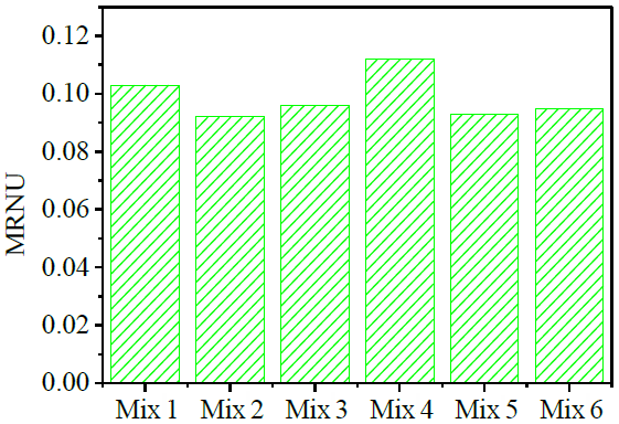
From Fig. 8, the difference between the MRR at the edge of the workpiece and the color bar at the center becomes lower. It is better than the distribution of the MRR when the damping is not adjusted, but different combinations have different effects on the workpiece surface, and the MRR distribution is also different. Mix 3 and Mix 6 have the worst MRRs, and Mix 1 has the least impact compared to other combinations. It can be seen in Fig. 9 that, by comparing different combinations of materials that remove non-uniformity, the material removal non-uniformity (MRNU) is (from small to large) Mix 2 < Mix 5 < Mix 6 < Mix 3 < Mix 1 < Mix 4. Thus, the material removal non-uniformity of Mix 4 is the largest, indicating that its material removal non-uniformity is the worst, and the material removal non-uniformity of Mix 2 is the smallest, indicating that its material non-uniformity is the best. It can be observed that the MRR of the workpiece after regulation is better than the MRR before regulation, and it is closer to the current level, so the scheme with a Mix 2 is finally selected for optimized FAP production.
All the experiments in this study were performed on a Kejing automatic pressure lapping and polishing machine (model UNIPOL-1200S). The sample was a C-plane sapphire substrate with a diameter of 50 mm.
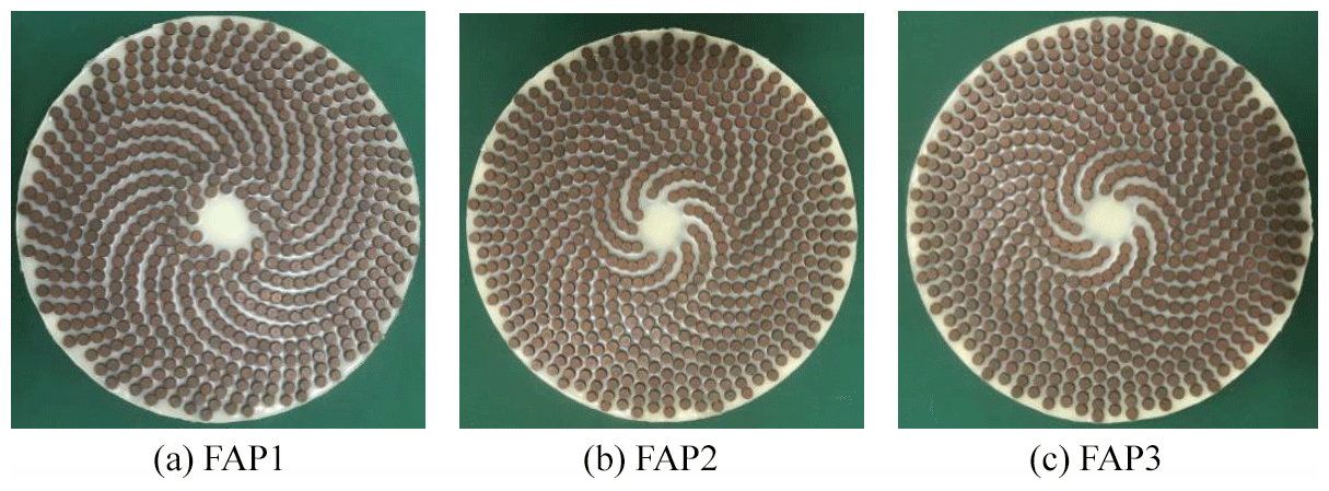
During lapping, the workpiece is attached to the loading tray for the rotation and revolving movement around the FAP. The lapping pressure is provided by the loading tray, so that the substrate is pressed against the upper and lower FAP surfaces to achieve lapping processing by the relative movement. To better compare the performance of the new type of FAP, the traditional FAPs are selected for experiments, as shown in Fig. 10. During the test, the thickness, surface roughness, and surface morphology of the substrate before and after lapping were measured, and finally, the surface morphology of the FAP was detected after the processing was completed. The thickness of the workpiece is measured with a thickness gauge (product nos. 325–312) produced by Dongguan Sanliang Precision Meter Co. Ltd. The surface roughness of the substrate is measured by a 3D optical profiler manufactured by Zygo as NewView 7300. The morphology of the abrasive tool was observed with an optical microscope, VHX-1000, manufactured by the Keyence Corporation.
The FAPs used in this experiment are shown in Fig. 10, which are α = 29∘ traditional pad FAP1, α = 35∘ traditional pad FAP2, and α = 35∘ optimized pad FAP3.

4.1 Surface morphology
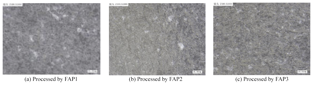
Figure 11 shows the surface morphology of the center regions of the sapphire after being processed by FAP1, FAP2, and FAP3. There are many bright spots in the center area of the workpiece surface when lapping with FAP1, relatively few bright spots in the edge area, and the surface morphology of the workpiece is very poor. Using the image processing method, the proportion of the surface defect area of the workpiece can be calculated. Among the three FAPs, the surface defects of the workpiece processed by FAP3 are 23 % less than that of FAP2 and 49 % less than that of FAP1, as shown in Fig. 12. The processing effect of FAP2 is better than that of FAP1. Compared with the other two pads, FAP3 has fewer bright spots in the center area, which indicates that the workpiece surface processed by the FAP3 pad has the best uniformity of material removal. In general, the surface processing effect of the workpiece processed by the three pads, in order from high to low, is FAP3 > FAP2 > FAP1.
4.2 Surface roughness
Figure 13 shows the changes in workpiece surface roughness at the loading of 2, 4, 6, and 8 g N (where g is the gravitational acceleration). A comparative analysis of the workpiece surface roughness after processing reveals that, as the pressure increases, the surface roughness of the workpiece decreases continuously, and the variation range is between 0.12 and 0.3 µm. This is because, during the processing, as the processing pressure increases, the force of the pellet on the working surface will increase accordingly, which will cause the MRR of the workpiece surface to increase, further reducing the workpiece surface roughness. When the pressure increases from 6 to 8 g N, the range of the roughness value of FAP3 is the largest. Figure 14 indicates the change in the surface roughness of the workpiece when the speed ratio is 0.9, 1.3, 1.5, and 1.7. The speed ratio is the ratio of the rotational speed of the FAP to the rotational speed of the workpiece. The surface roughness of the workpiece after processing is compared and analyzed. It can be concluded that the roughness value of the workpiece surface fluctuates between 0.09 and 0.17 µm. As the speed ratio increases, the workpiece surface roughness fluctuates greatly. When the speed ratio is 1.5, the surface roughness of the workpiece processed by the FAP3 is the lowest. At the same time, the surface roughness of the workpiece processed by FAP3 is the lowest under the four rotational speed ratios, which indicates that FAP3 has better machining performance. In addition, it can be seen that the selection of the appropriate speed ratio can improve the surface quality of the workpiece.
4.3 MRR of different workpiece processed by FAPs
Figure 15 is the change in the MRR of the FAP on the workpiece when the working pressure is 2, 4, 6, and 8 g N. It can be seen from Fig. 15 that as the working pressure increases, so the workpiece removal rate also gradually increases. This is known from the Preston equation, which proves that when the pressure increases then the pressure on the workpiece surface caused by the pellet on the surface of the FAP also increases, causing the MRR of the workpiece surface to increase. When the working pressure is 2, 4, 6, and 8 g N, the MRR of the FAP2 on the workpiece is higher than that of FAP1 on the workpiece, but, under the four different pressure conditions, the MRR of the FAP3 is higher than the others. From the general trend of the MRR of the workpiece, it can be determined that the MRR of the processed workpiece, in order from high to low, is FAP3 > FAP2 > FAP1.
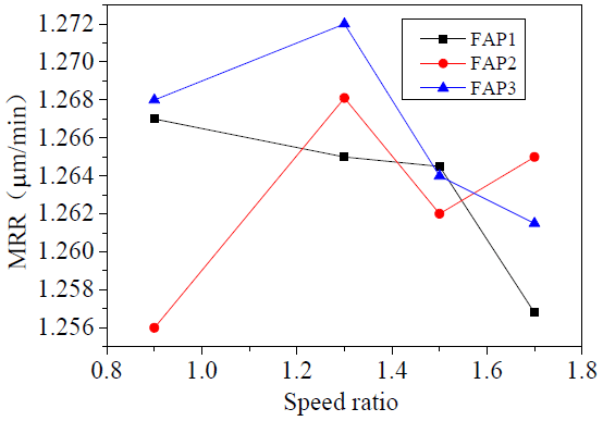
By analyzing the changes in the MRR in Fig. 16, the MRR of the workpiece surface fluctuates greatly at different speed ratios, which roughly increases first and then decreases. When the speed ratio is 1.3, the rate of removing material from the workpiece surface is the largest. When comparing and analyzing the MRRs of workpieces processed by the three FAPs under four different speed ratios, except when the speed ratios were k = 1.5 and k = 1.7, the MRR of FAP3 on the workpiece surface is higher than that of the other FAPs. In addition, it can be seen from Fig. 16 that the speed ratio affects the distribution of the MRR, and the speed ratio should not be too high or too low; an appropriate speed ratio can achieve higher workpiece MRR.
4.4 Material removal thickness
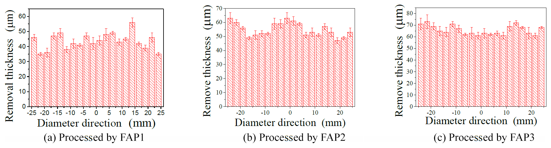
Samples of three types of FAPs with a working pressure of 2 g N, a speed ratio of 1.3, and a processing time of 1 h were taken. By measuring the thickness of the workpiece surface before and after processing, the thickness of the workpiece surface can be obtained, and 20 workpieces in the diameter direction were measured, as shown in Fig. 17.
By comparing the thickness of the three FAPs before and after processing the workpiece, the average removal thickness of the three FAPs on the workpiece surface is 43.5, 55.65, and 65.8 µm. And it is indicates that the processing efficiency of FAP3 is greater than that of the other two FAPs. The processing efficiency of FAP2 is the second best, and the processing effect of FAP1 is the worst. Through calculation, the standard deviations of the removal thickness of the three FAPs on the workpiece are 5.336, 4.898, and 4.034 µm, respectively. FAP3 was lower than the two traditional FAPs by 24.4 % and 17.6 %, respectively. It is shown that the non-uniformity of the thickness of FAP3 is the best, the non-uniformity of the thickness of FAP2 is the second best, and the non-uniformity of the thickness of FAP1 is the worst. It was also verified that the processing effect of FAP3 is better than that of FAP2, and the processing effect of FAP2 is better than that of FAP1.
From the above results, the newly designed FAPs have a better processing performance through the coupling of the adjustment of the pellet arrangement and the distribution design of the damping layer. This is because the pressure distribution on the workpiece surface is uniform. The abrasive particles cut into the workpiece are much the same, so the number of abrasive particles removed is uniform. Moreover, the increase in abrasives involved in processing increases the processing efficiency. Therefore, it can be seen from the experimental results that the optimized FAP processing workpiece surface quality is better.
In order to improve the processing efficiency and processing quality of the sapphire substrate, in this paper, a new type of FAP is designed and optimized and is coupled by the arrangement of the pellet and the damping adjustment of the damping layer. By adjusting the angle of the spiral arrangement of the FAP and the damping distribution of the damping layer, a better pressure distribution can be obtained, thereby allowing for better processing quality. The processing effects of different FAPs on the workpiece surface were compared, including the material removal rate, material removal thickness, and surface roughness. The results show that the surface processing effect of the workpiece processed by the three FAPs, in order from high to low, is FAP3 > FAP2 > FAP1. Meanwhile, the influence of machine parameters on the processing effect of FAP is analyzed. Except when the speed ratios are k = 1.5 and k = 1.7, the MRR of the FAP3 on the workpiece surface is highest compared to that of the FAP. In addition, the speed ratio affects the distribution of the MRR. So, an appropriate speed ratio can achieve a higher workpiece MRR. The surface roughness distribution of FAP3 is the lowest at different speed ratios, indicating that, under these several speed ratios, the surface roughness of the workpiece by FAP3 is the best, and it can be concluded that the existence of a proper speed ratio can improve the machine effect of the workpiece surface. Therefore, considering the multi-factor coupling design of the FAP has significance for ultra-precision machinery with a large size and high efficiency.
The data used in this study can be requested from the corresponding author.
CX participated in the theoretical modeling, experimental research, and writing of this paper. CF's major contributions to this paper are the experimental design and guidance, as well as the revision of the paper. YL improved the experimental scheme, guided the theoretical model, and modified the paper. CL participated in theoretical simulation and experimental data processing.
The authors declare that they have no conflict of interest.
This article is part of the special issue “Robotics and advanced manufacturing”. It is not associated with a conference.
This research has been supported by National Natural Science Foundation of China (grant no. 51675193) and the Subsidized Project for Cultivating Postgraduates' Innovative Ability in Scientific Research of Huaqiao University (grant no. 18013080037).
This research has been supported by the National Natural Science Foundation of China (grant no. 51675193) and the Subsidized Project for Cultivating Postgraduates' Innovative Ability in Scientific Research of Huaqiao University (grant no. 18013080037).
This paper was edited by Peng Li and reviewed by two anonymous referees.
Arunachalam, A. P. S., Idapalapati, S., and Subbiah, S.: Multi-criteria decision-making techniques for compliant polishing tool selection, Int. J. Adv. Manuf. Tech., 79, 519–530, https://doi.org/10.1007/s00170-015-6822-y, 2015.
Belkhir, N., Aliouane, T., and Bouzid, D.: Correlation between contact surface and friction during the optical glass polishing, Appl. Surf. Sci., 288, 208–214, https://doi.org/10.1016/j.apsusc.2013.10.008, 2013.
Dong, Z. C. and Cheng, H. B.: Study on removal mechanism and removal characters for SiC and fused silica by fixed abrasive diamond pellets, Int. J. Mach. Tool. Manu., 85, 1–13, https://doi.org/10.1016/j.ijmachtools.2014.04.008, 2014.
Fang, C. F., Zhao, Z. X., Lu, L. Y., and Lin, Y. F.: Influence of fixed abrasive configuration on the polishing process of silicon wafers, Int. J. Mach. Tool. Manu., 88, 1–10, https://doi.org/10.1007/s00170-016-8808-9, 2017.
Fang, C. F., Liu, C., Zhao, Z. X., Lin, Y. F., Hu, Z. W., and Xu, X. P.: Study on geometrical patterns of textured fixed-abrasive pads in sapphire lapping based on trajectory analysis, Precis. Eng., 53, 169–178, 2018.
Fang, C. F., Yan, Z., Deng, W. W., and Zhang, L. C.: Material removal in grinding sapphire wafers with brazed–diamond pellet plates, Mater. Manuf. Process., 34, 791–799, https://doi.org/10.1080/10426914.2019.1594260, 2019.
Kang, J. and Hadfield, M.: Examination of the material removal mechanisms during the lapping process of advanced ceramic rolling elements, Wear, 258, 2–12, https://doi.org/10.1016/j.wear.2004.09.017, 2005.
Li, M.: Pattern optimization of polished abrasive pad and performance evaluation of polishing pad, MA thesis, Mechanical Manufacturing and Automation, Nanjing University of Aeronautics and Astronautics, Nanjing, China, 86 pp., 2010.
Liang, Z. Q., Wang, X. B., Wu, Y. B., Xie, L. J., Liu, Z. B., and Zhao, W. X.: An investigation on wear mechanism of resin-bonded diamond wheel in Elliptical Ultrasonic Assisted Grinding (EUAG) of monocrystal sapphire, J. Mater. Process. Tech., 212, 868–876, 2012.
Liu, B.: Effect of polishing pad surface structure and organization on CMP, MA thesis, School of Mechanical Engineering, Dalian University of Technology, China, 64 pp., 2006.
Liu, C.: Structure Design and Dynamics Simulation study of bionic flapping wing Aircraft, MA thesis, School of architecture, Harbin Institute of Technology, China, 60 pp., 2010.
Lv, Y. S., Li, N., Wang, J., Zhang, T., Duan, M., and Xing, X. L.: Analysis on the Contact Pressure Distribution of Chemical Mechanical Polishing by the Bionic Polishing Pad with Phyllotactic Pattern, Adv. Mater. Res., 215, 217–222, https://doi.org/10.4028/www.scientific.net/AMR.215.217, 2011.
Pan, H. B.: Preparation and properties of bionic superhydrophobic coating, MA thesis, College of Chemical Engineering and Environment, North University of China, China, 68 pp., 2015.
Qiu, J., Chen, Z. X., Wei, S. J., Qiu, B., Zhang, X. J., and Zhou, Y. M.: Ordered arrangement of diamond abrasive particles based on PRO/E and simulation of its motion trajectory, Superhard Material Engineering, 24, 21–24, https://doi.org/10.3969/j.issn.1673-1433.2012.06.005, 2012.
Rao, P. K., Bhushan, M. B., Bukkapatnam, S. T. S., Kong, Z. Y., Byalal, S., Beyca, O. F, Fields, A., and Komanduri, R.: Process-Machine Interaction (PMI) Modeling and Monitoring of Chemical Mechanical Planarization (CMP) Process using Wireless Vibration Sensors, IEEE T. Semiconduct. M., 27, 1–15, https://doi.org/10.1109/TSM.2013.2293095, 2014.
Sokol, J. J., Kim, D., Nabulsi, F., Zhang, H., Atkinson, M. R., Romero, V. D., Gagliardi, J. J., and Zazzera, L. A.: A case for 2-body material removal in prime LED sapphire substrate lapping and polishing, J. Manuf. Process., 15, 348–354, https://doi.org/10.1016/j.jmapro.2012.11.005, 2013.
Tam, H. Y., Cheng, H. B., and Wang Y. W.: Removal rate and surface roughness in the lapping and polishing of RB-SiC optical components, J. Mater. Process. Tech., 192, 276–280, 2007.
Vogel, H.: A better way to construct the sunflower head, Math. Biosci., 44, 179–189, https://doi.org/10.1016/0025-5564(79)90080-4, 1979.
Yang, N., Zong, W. J., Li, Z. Q., and Sun, T.: Wear process of single crystal diamond affected by sliding velocity and contact pressure in mechanical polishing, Diam. Relat. Mater., 58, 46–53, https://doi.org/10.1016/j.diamond.2015.06.004, 2015.
Zha, L. Y.: Pressure Distribution of Planar Optical Parts in Processing, Instrument Technique and Sensor, 1, 8–12, CNKI:SUN:YBJS.0.1984-01-002, 1984.
Zhang, N. C., Wang, P., Hua, X., Ren, J., and Liu, F. S.: Optical Radiation Characteristics and Structural Phase Transition of Sapphire under Megabar Pressure, Acta Optica Sinica, 39, 442–448, https://doi.org/10.3788/AOS201939.0730002, 2019.
Zhang, W., Yang, X. H., Hu, X. Y., and Hu, Z. H.: Theoretical study on the pressure in the contact zone between the grinding tool and the workpiece in surface grinding, Journal of Harbin Institute of Technology, 36, 667–669, https://doi.org/10.3321/j.issn:0367-6234.2004.05.029, 2004.