the Creative Commons Attribution 4.0 License.
the Creative Commons Attribution 4.0 License.
 | 10 Sep 2021
The approximate calculation of the natural frequencies of a Stockbridge type vibration damper and analysis of natural frequencies' sensitivity to the structural parameters
Qing Yin
Jianli Zhao
Yisheng Zhang
Vibration damper is widely used in overhead transmission lines to alleviate aeolian vibration. Its natural frequencies are important parameters for a vibration damper. In this paper, the approximate calculation formulas of natural frequencies of the one-side subsystem of a Stockbridge type vibration damper were derived and the design sensitivity analysis of the natural frequencies was studied using partial differential equations with respect to each concerned parameter including the length of the steel strand, the mass of the counterweight, the eccentric distance, and the radius of gyration of the counterweight. Through a case study that considered a variation of up to ±30 % in the values of the design parameters, the exact calculation and approximate calculation results of the natural frequencies were analysed, and the sensitivity of the vibration damper's natural frequencies to the design parameters was studied. The results show that, within the range of the parameters used in this study, the approximately calculated first-order frequency is lower than the exact values, whereas the approximately calculated second-order frequency is larger than the exact values. The sensitivity analysis indicates that the first-order frequency is highly sensitive to the steel strand's length, whereas it is moderately sensitive to the counterweight's mass and slightly sensitive to the eccentric distance and the gyration radius of the counterweight; the second-order frequency is highly sensitive to the steel strand's length and the gyration radius of the counterweight, moderately sensitive to the counterweight's mass, and slightly sensitive to the eccentric distance. It will provide theoretical guidance and approximate analysis method in engineering for the design of the vibration damper.
- Article
(4194 KB) - Full-text XML
- BibTeX
- EndNote


When the natural wind blows over the overhead transmission lines, the transmission lines vibrate due to the effect of Kármán vortex street (Dutkiewicz and Machado, 2019), and it is called aeolian vibration of the transmission lines (Barry et al., 2012; Foti and Martinelli, 2018; Dutkiewicz and Machado, 2019; Si et al., 2020). The wind speed ranges from 1 to 7 m s−1, and the frequency of aeolian vibration, depending on the conductor diameter and the wind speed, ranges from 3 to 150 Hz (Barry et al., 2012; Bukhari and Barry, 2018; Bukhari et al., 2018; Dutkiewicz and Machado, 2019). The vibration amplitude of the conductor is the same order of the conductor's diameter (Luo et al., 2016) and usually less than the conductor's diameter (Barry et al., 2012; Bukhari et al., 2018; Dutkiewicz and Machado, 2019). The vibration of the conductor increases the bending stress of the conductor, and long-time vibration of the conductor will cause fatigue fracture of the strands of the conductor, then the fracture of the whole conductor (Bukhari and Barry, 2018; Dutkiewicz and Machado, 2019; Qi et al., 2019). Besides, the vibration of the conductor also results in wear of the power fittings, bringing damage to the power fittings and power line pylons (Bukhari et al., 2018). Therefore, aeolian vibration of the conductor will seriously threaten the running safety of the transmission lines. To reduce the vibration amplitude to the allowable fatigue limit line, some protective devices have been developed and used in the transmission lines. Among these devices, a Stockbridge type vibration damper, which was invented by Stockbridge (1928), is widely used for its wide range of frequencies (Bukhari and Barry, 2018; Bukhari et al., 2018; Foti and Martinelli, 2018; Barbieri et al., 2019).
Figure 1 shows a Stockbridge type vibration damper (steel strand is simplified as a cylinder in Fig. 1) which was studied in this study. This type of vibration damper consists of two flexible steel strands (also known as “messenger cable”) which are attached to a counterweight (damper mass) at either end. When a vibration damper is used in the electric industry, the clamp is bonded with the conductor. Therefore, the clamp vibrates with the conductor in the wind. Since the two counterweights have a large weight, meaning a large inertia, and the stiffness of the steel strand is low, the two counterweights cannot vibrate synchronously with the clamp. As a consequence, internal friction between the strands of the steel strand consumes the vibration energy of the conductor, restraining the vibration of the conductor (Zhan et al., 2011; Barry et al., 2015; Foti and Martinelli, 2018; Wang et al., 2021). The vibration of the vibration damper is the most intense at its natural frequencies, and thus the vibration damper consumes more energy, affording better anti-vibration effect. Therefore, the natural frequencies of the vibration damper should be in the protected frequency range, especially in the dangerous frequency range (Vaja et al., 2018). As a result, the structure design and the calculation of the natural frequencies of the vibration damper are of high importance. Besides, it is necessary to determine the vibration modes corresponding to the natural frequencies of the vibration damper by theoretical means, while the approximate calculation of natural frequencies is helpful to determine the vibration modes of the vibration damper. And a simple approximate calculation also helps the related engineers to calculate the natural frequencies and analyse the natural frequencies' sensitivity to the structural parameters.
Therefore, the approximate calculation formulas of natural frequencies of the one-side subsystem of a Stockbridge type vibration damper were derived, and the design sensitivity analysis of the natural frequencies was studied using partial differential equations with respect to each concerned structure design parameter. Through a case study that considered a variation of up to ±30 % in the values of the design parameters, the exact calculation and approximate calculation results of the natural frequencies were analysed, and the sensitivity of the natural frequencies of the vibration damper to the design parameters was also studied. This study can provide theoretical guidance and approximate analysis method in engineering for the design of the vibration damper.
Researchers have done much work on the true nature and operation mechanism of a Stockbridge type vibration damper (Wang et al., 2021). We just discuss damper alone here, and dampers with transmission lines are beyond the scope of this paper. Claren and Diana (1969) assume the two halves of the Stockbridge type damper opposite to the clamp to be identical, and the one-side subsystem (Fig. 2) can be considered as a cantilever with mass concentrated at the extremity. As shown in Fig. 2, the subsystem consists of a cantilever beam (steel strand) and a counterweight (damper mass). The counterweight is considered to be a rigid body meaning that, regardless of the elasticity, only the mass and moment of inertia were considered (Claren and Diana, 1969). Since the mass of the steel strand is far less than that of the damper mass, only the elasticity of the steel strand is considered, ignoring the steel strand's damping, mass, and moment of inertia (Claren and Diana, 1969). Therefore, a 2-degree-of-freedom linear model is adopted to understand the vibration characteristics. Then the natural frequencies of one-side subsystem of the damper under free motion were calculated by solving vibration equations, and it indicated that the one-side subsystem had two natural frequencies (Claren and Diana, 1969). This is a classic linear model, and it refers to Sect. 3. Besides, as shown in Fig. 3, experiments showed that the lower mode of vibration describes the counterweight rotating around an axis passing through the attachment point between the steel strand and the clamp, and the second mode describes the counterweight rotating around an axis passing through the centroid of the counterweight (Claren and Diana, 1969). However, the vibration modes were not determined through theoretical method. Wagner et al. (1973) established a theoretical analysis of the response characteristics of Stockbridge dampers including undamped natural frequencies and forced vibration, and then the theoretical predictions were verified experimentally. Using this linear model (Claren and Diana, 1969), Zhan et al. (2011) discussed the effects of the structural parameters on the power characteristics of a Stockbridge damper; Kim (2017) developed an approximate calculation method of the natural frequencies, and the sensitivity to the structural parameters was also analysed through both formula and case studies. Nevertheless, the approximate calculation formulas of the natural frequencies in the work of Kim (2017) are problematic, and thus the sensitivity analysis is questionable. Generally speaking, a one-side damper with two natural frequencies can be described by the classic above linear model if damping is not considered (Claren and Diana, 1969). However, considering the damping, characteristics of the messenger cable, one-side damper with more than two natural frequencies, and so on, this linear model cannot be used. Regardless of damping, Vaja et al. (2018) present an analytical model of a novel aeolian vibration damper with an increased number of natural frequencies using Hamilton's principle, and the natural frequencies of this damper were deduced. Li et al. (2018) established a theoretical calculation model without damping for FDZ-type dampers that have three natural frequencies in one-side through space geometry and dynamics. It was found that peak power and peak frequency in model and experiments agree well with each other.
Figure 3Mode shapes of the beam-counterweight system: (a) the first mode; (b) the second mode.
Nonlinear dynamic characteristics of the Stockbridge type vibration damper are hot topics in recent years, and the nonlinearity is mainly caused by the messenger cable. The nonlinearity of the messenger cable is due to the local hysteretic character of the damping mechanism, resulted from Coulomb's dry friction between the cable wires (Foti and Martinelli, 2018; Wang et al., 2021). Leblond and Hardy (1999) assumed that the messenger cable is characterized by a hysteretic loss factor associated with its complex bending stiffness, and this model was used in the work of Barbieri and Barbieri (2012) and Barbieri et al. (2016). Sauter and Hagedorn (2002) proposed a Jenkins element which consists of one linear spring and one Coulomb's friction element in parallel to model the hysteresis for the cable. In other studies (Barbieri et al., 2016; Foti and Martinelli, 2018), the Bouc–Wen model was used to model the hysteretic behaviour of the messenger cable. The Bouc–Wen model parameters are identified from experimental results, and this model can be recognized as adequate to represent the local (cross-sectional) behaviour mainly controlled by the internal sliding of the steel strands. Besides, the Euler–Bernoulli beam was also used to characterize the nonlinear behaviour of the messenger cable (Barbieri and Barbieri, 2012; Langlois and Legeron, 2014; Barry et al., 2015; Bukhari and Barry, 2018). Barbieri et al. (2019) used a model that consists of a nonlinear cantilever beam with a tip mass to analyse the messenger cables of a Stockbridge. The nonlinear portion of rigidity (caused by curvature) and nonlinear damping (proportional to the nonlinear stiffness matrix) were considered in this model. The experimental results showed that the flexural rigidity changed little when the damper was on a cam machine that allows the system to be excited with constant displacement; however, the flexural rigidity had great variations when the damper was on a shaker with constant acceleration. It is worth noting that the contact conditions between each two parts of the damper have significant influence on the stiffness of the whole structure (Luo et al., 2016), and it causes nonlinearity. However, analytic models cannot describe this phenomenon. With a finite element numerical model, these nonlinear vibration characteristics of the damper can be reflected well (Luo et al., 2016).
In this work, we try to obtain the approximate calculation of the natural frequencies of a Stockbridge type vibration damper and the natural frequencies' sensitivity to the damper's structural parameters, and thus, the nonlinearity of the damper was ignored. The model in the work of Claren and Diana (1969) was used. As shown in Fig. 2, point O is the mass centre of the counterweight; point O′ is the attachment point of the steel strand and the damper mass; s is the distance between O and O′, also be called eccentric distance; L is the distance between O′ and the clamp, i.e. the length of the steel strand; m is the mass of the counterweight. Figure 3 shows the two mode shapes of the beam-counterweight system. Because the clamp is attached to a transmission line, a displacement of U is produced. As a result, the damper mass obtains a displacement of y, and a rotation angle of φ is also produced. The governing equations (Claren and Diana, 1969) for the subsystem are
where E and I are Young's modulus and the second moment of inertia of the steel strand, respectively. is the moment of inertia of the counterweight rotating around an axis passing through point O′. Assume that the vibration equations of the counterweight are
where y0 and φ0 are the amplitude of the counterweight's displacement and rotation angle, respectively; j is the imaginary unit and ω is the circular frequency of vibration. Then the two circular frequencies (Claren and Diana, 1969) of vibration are obtained by solving Eqs. (1) and (2):
JO, the moment of inertia of the counterweight rotating around an axis passing through point O, has a relationship with :
Assuming that the radius of gyration of the counterweight is R, JO can be described as
Inserting Eqs. (4) and (5) into Eq. (3) yields the circular frequencies of vibration:
Equation (6) is the exact calculation of the two circular frequencies of vibration. The relationship between the two circular frequencies of vibration can be derived using Eq. (6), as shown in Eq. (7):
To approximately calculate the natural frequencies, assume that point O and point O′ coincide, i.e. s=0. Then Eq. (6) yields
Using the second order of Taylor's expansion, the part containing the square root in Eq. (8) is expanded at R=0. Then the first-order circular frequency of vibration can be expressed as
Hence, the first-order circular frequency of vibration is approximately
Combining with Eq. (7), the second-order circular frequency of vibration is approximately
Finally, the approximate two natural frequencies of the vibration damper f1, f2 are
The second moment of inertia of the steel strand has a relationship (Shao et al., 2003) with the diameter of a single strand (d) and the number of strands (n):
As is known, the natural frequency (f) of a vibration system is
where k is the equivalent stiffness of the system and M is the inertial parameter of the system. In a translational motion, k is the translation stiffness and M is the mass. Similarly, in a rotary movement, k is the rotation stiffness and M is the moment of inertia. As described in Fig. 3, the first-order mode of vibration corresponds to a vertical displacement of the mass centre of the counterweight with very small rotations, whereas the second-order mode of vibration corresponds to the rotation of the counterweight about its mass centre with almost no vertical displacements (Claren and Diana, 1969). In low-mode vibration (Fig. 3a), the steel strand is mainly flexural vibration, and the vibration amplitude is large. However, in high-mode vibration (Fig. 3b), the steel strand vibrated with bending, leading to an increase of the internal friction in the strand steel, and thus the vibration amplitude decreases. Then the natural frequencies of the beam-counterweight system can also be calculated using Eq. (14). According to the mechanics of materials, the translation and rotation stiffness of the free end of a cantilever beam are approximately and , respectively. Inserting the stiffness parameters and inertial parameters into Eq. (14), then Eq. (12) can also be obtained. Obviously, the approximate calculation formulas of the natural frequencies of the vibration damper are the same in the two kinds of calculation methods. As a consequence, the derivation process of the approximate calculation formulas in Eqs. (8) to (12) is reasonable.
Besides, the approximate calculation formulas in Eq. (12) indicate the vibration modes of the damper. Considering the cable's length (L) is far greater than the gyration radius of the counterweight (R), f2 in Eq. (12) is greater than f1, meaning that the low-mode vibration is translational motion and the high-mode vibration is rotary motion under approximate situation. However, the vibration modes of the damper cannot be judged according to the accurate calculation formulas, i.e. Eqs. (3) and (6). But the size of the natural frequencies' values can be determined according to Eqs. (3) and (6). As a result, the accurately calculated first-order frequency corresponds to translational motion and the second-order frequency corresponds to rotary motion. At the same time, it also demonstrates that the assumed two vibration modes (Claren and Diana, 1969) in Fig. 3 are correct.
4.1 Theoretical analysis
According to Eq. (6), the natural frequencies of the vibration damper are mainly affected by the following factors: the mass of the counterweight (m), the length of the steel strand (L), the radius of gyration of the counterweight to its mass centre (R), the bending stiffness of the steel strand (EI, generally unchanged), distance between the mass centre of the counterweight and the attachment point of the counterweight (s). The design sensitivity analysis of the natural frequencies was studied using partial differential equations with respect to each concerned parameter. Since Eq. (6) is complicated, the partial differential equations are difficult to tell the sensitivity relative to parameters L and R, so the approximate calculation formula of natural frequencies, i.e. Eq. (12), was used to analyse the sensitivity. As for parameters s and m, the exact calculation formula of natural frequencies, i.e. Eq. (6), was used to analyse the sensitivity.
According to Eq. (6), the partial differential equations of natural frequencies with respect to m and s are as follows:
According to Eq. (12), the partial differential equations of natural frequencies with respect to parameters L and R are as follows:
Seen from Eqs. (15) and (16), negative signs are in both equations, indicating that the two natural frequencies decrease with the increase of parameter m. Additionally, sensitivity of the two natural frequencies with respect to parameter m is the same because the differential formulae in Eqs. (15) and (16) are proportional to . For eccentricity s, it is usually less than half of the length of the steel strand L. Therefore, the partial derivative of the first-order frequency with respect to parameter s is positive, and the partial derivative of the second-order frequency with respect to parameter s is negative. Thus, the first-order frequency increases with the increase of parameter s, whereas the second-order frequency decreases with the increase of parameter s. However, the frequency sensitivity with respect to parameter s is difficult to determine due to Eqs. (17) and (18) being complex. Seen from Eqs. (19) and (20), the frequencies of both orders decrease with the increase of parameter L. The first-order frequency is more sensitive to parameter L than the second-order frequency because the differential formula Eqs. (19) and (20) are proportional to and , respectively. Equations (21) and (22) indicate that parameter R has less influence on the first-order frequency, whereas the second-order frequency decreases with the increase of parameter R, meaning that the second-order frequency is more sensitive to parameter R.
In summary, the first-order frequency is highly sensitive to parameter L, moderately sensitive to parameter m, and slightly sensitive to parameter R. The second-order frequency is highly sensitive to parameter R and moderately sensitive to parameters L and m. Though the frequency sensitivity with respect to parameter s is not sure, the tendency of frequency to vary with parameter s is determined. But it does not matter; the sensitivity to parameter s can be determined by a case study using the exact calculation formula of natural frequencies. And the accuracy of the above conclusions can also be verified in combination with the case study. See the details in the following.
4.2 Case study
The vibration damper in this study has a symmetric structure, meaning the damper has two natural frequencies, and therefore, only half of the damper was studied. The structure parameters of the vibration damper as shown in Fig. 1 are listed in Table 1. To study the sensitivity to structure parameters, case studies for exactly calculating the two natural frequencies were carried out by changing the structure parameters. The structure parameter values in Table 1 were considered the reference values, and the limits of parameter variation were set to ±30 % of the reference values. The two natural frequencies calculated using the reference structure parameters were considered the reference frequencies. Besides, the two natural frequencies were also approximately calculated using Eq. (12), and the errors of approximate calculation were also calculated. Changing rate of frequency is used to describe the changing of the frequency with respect to the reference frequency, and it is defined as
where Cf, fc, and fr are the changing rate of frequency, the changed frequency, and the reference frequency, respectively. Changing rate of frequency can characterize the sensitivity of the two frequencies to the change of the same structural parameter. Note that the variations of the structure parameters were just used to calculate the natural frequencies in terms of the maths, and a variation of up to ±30 % is a sufficient range for the case study considering the design of a vibration damper in reality. Besides, in practice, only the change of parameter L will not cause the change of parameters m, s, and R, and vice versa. However, parameters m, s, and R may affect each other, meaning that changing one parameter alone will cause the change of the other two parameters. The calculation results are shown in Figs. 4–6.
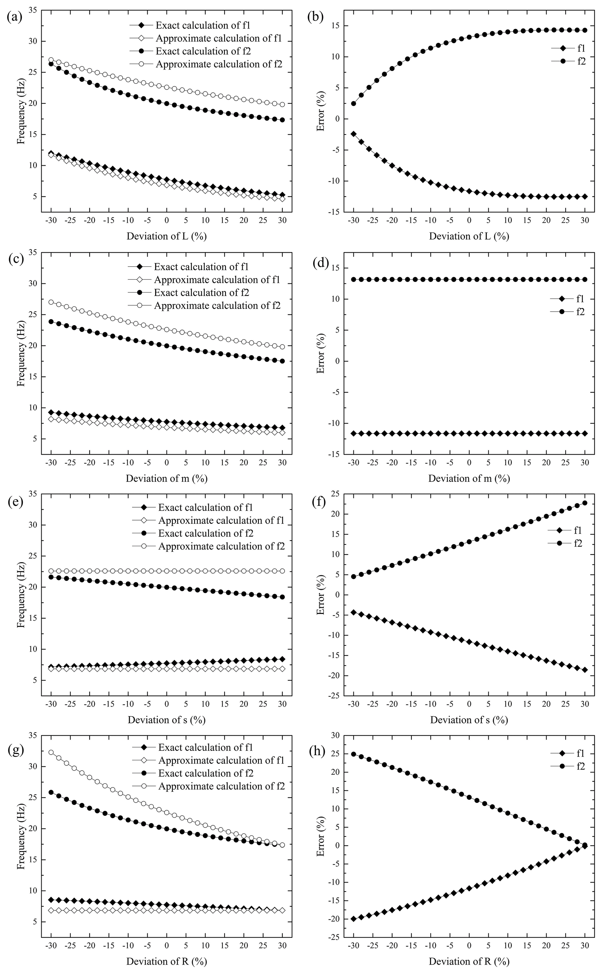
Figure 4The exact and approximate calculation results of the two natural frequencies of the vibration damper with the variations of its structural parameters: calculation results (a) and approximate calculation errors (b) when L changes; calculation results (c) and approximate calculation errors (d) when m changes; calculation results (e) and approximate calculation errors (f) when s changes; calculation results (g) and approximate calculation errors (h) when R changes.
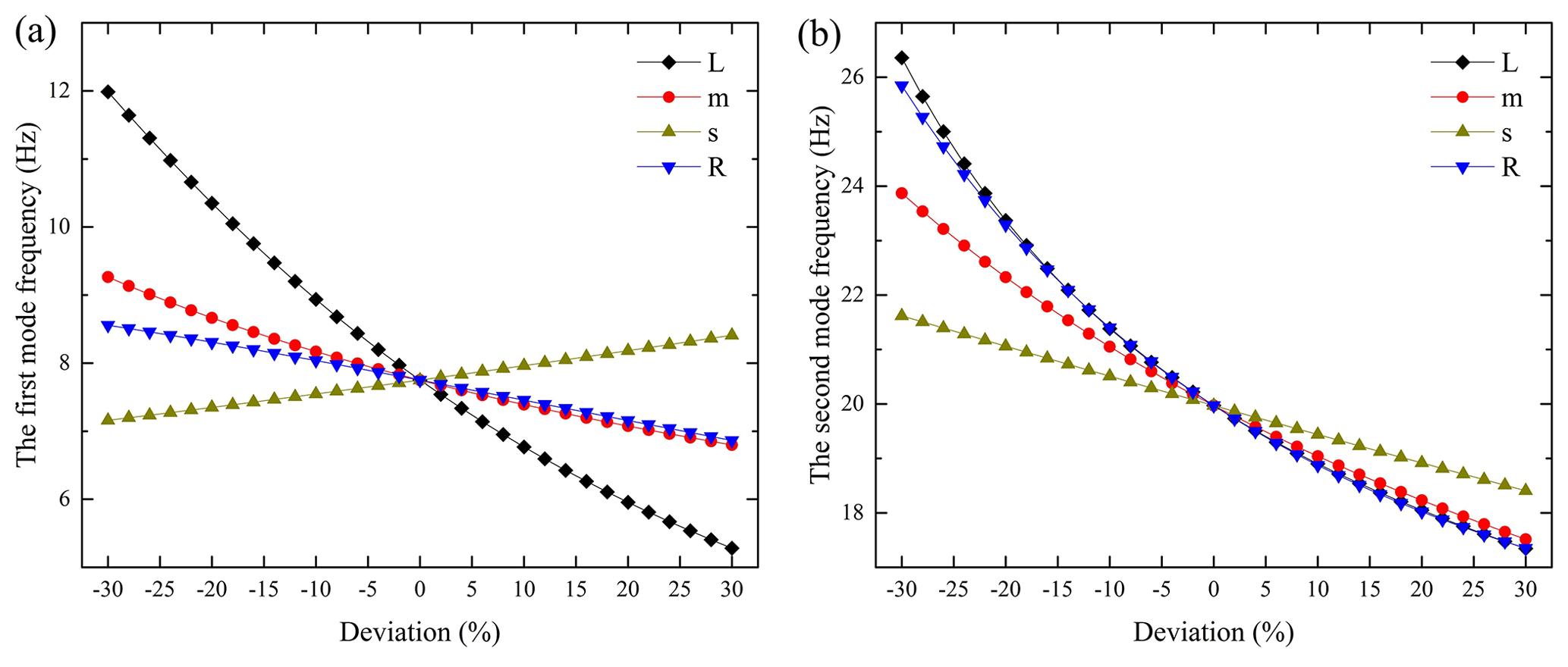
Figure 5Variations of the natural frequencies with the changes of vibration damper's structural parameters: (a) the first-order natural frequency, (b) the second-order natural frequency.
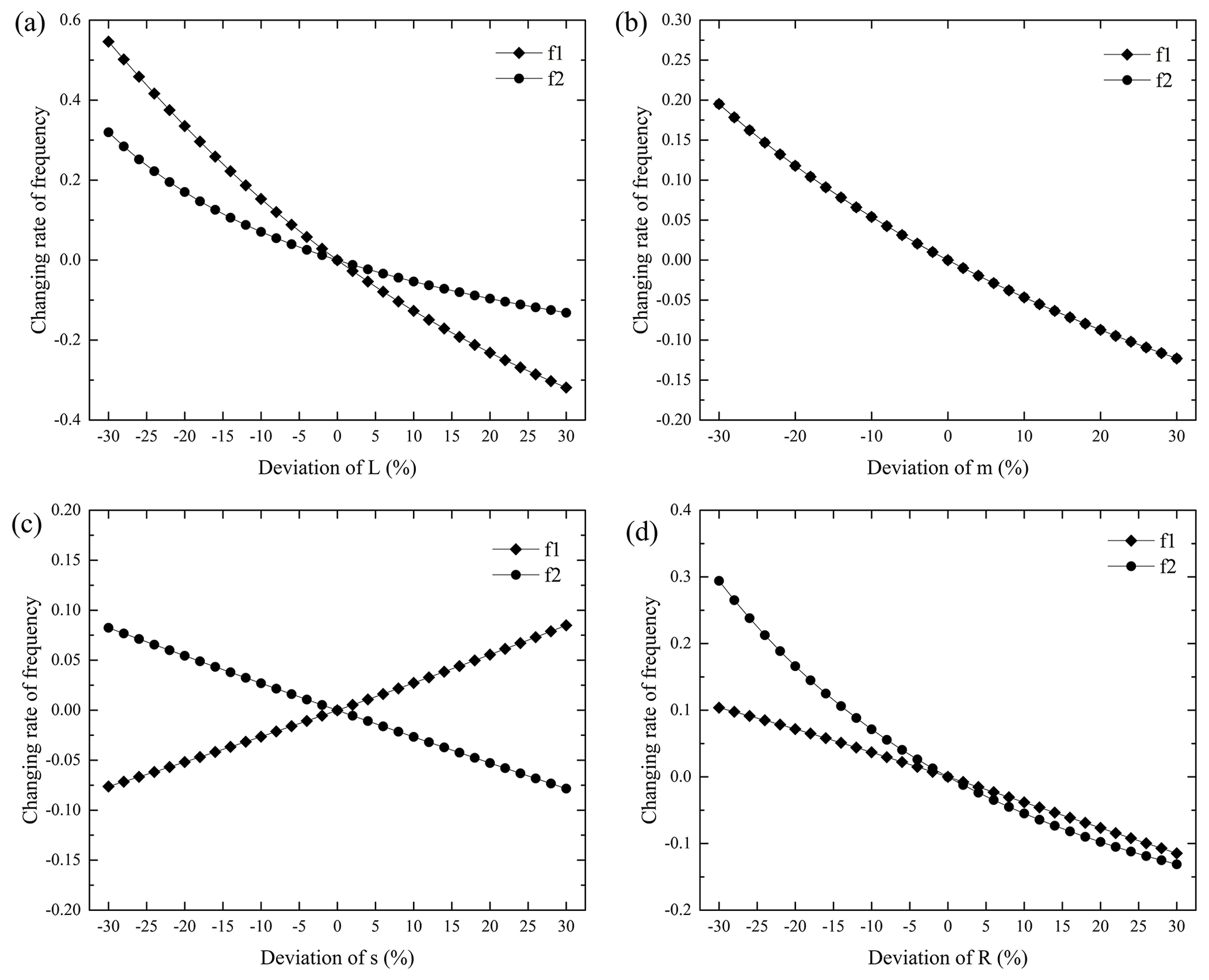
Figure 6Changing rates of the natural frequencies with the changes of vibration damper's structural parameters: (a) L changes, (b) m changes, (c) s changes, (d) R changes.
Seen from Fig. 4a and c, when parameters L and m vary in the range of ±30 %, the approximately calculated values and the exactly calculated values of the two frequencies are consistent in their variation trend; that is, the two frequencies decrease with the increase of parameters L and m. In addition, the first-order frequency obtained by approximate calculation is lower than exact calculation results, whereas the second-order frequency obtained by approximate calculation is larger than exact calculation results. The calculation errors caused by the changes in these two parameters are different. When parameter L changes, the calculation errors of the first-order frequency increase from about −2.5 % to about −12.5 %, whereas the calculation errors of the second-order frequency increase from about 2.5 % to about 14.3 % (Fig. 4b). When parameter m changes, the calculation errors of the two frequencies remain unchanged, and the errors are about −11.63 % and 13.16 % (Fig. 4d), respectively. According to the error calculation method, combined with Eqs. (6) and (12), it can be simply proved that the error has nothing to do with parameter m and is only related to parameters L, s, and R. Note the proof is omitted.
Since parameter s is not involved in the approximate calculation, the approximate calculation results were not affected by parameter s when it varies in the range of ±30 % (Fig. 4e). Similar to the variations of parameters m and L, the first-order frequency obtained by approximate calculation is lower than exact calculation results, whereas the second-order frequency obtained by approximate calculation is larger than the exact calculation results (Fig. 4e). The exact calculation results indicate that the first-order frequency increases with the increase of parameter s, whereas the second-order frequency decreases with the increase of parameter s (Fig. 4e). Obviously, according to the derivation process of approximate calculation method, the smaller the parameter s, the smaller the calculation errors, which are consistent with the calculation results (Fig. 4f).
When parameter R changes within the range of ±30 %, the first-order frequency obtained by approximate calculation is lower than the exact calculation results, whereas the second-order frequency obtained by approximate calculation is larger than exact calculation results (Fig. 4g). The approximate values' tendency of the second-order frequency is consistent with the exact values' tendency; that is, the increase of parameter R will cause the decrease of the second-order frequency (Fig. 4g). And the trend of the second-order frequency calculated by the exact method is the same as that of the first-order frequency. It can be seen from Eq. (12) that parameter R has no influence on the approximate calculation results of the first-order frequency, which agrees with the calculation results as shown in Fig. 4g. The calculation errors of the first-order frequency decrease from about −20 % to about −0.18 %, whereas the calculation errors of the second-order frequency decrease from about 25 % to about 0.18 % (Fig. 4h).
In general, when parameters L, m, s, and R vary in the range of ±30 %, the first-order frequency obtained by approximate calculation is lower than the exact calculation results, whereas the second-order frequency obtained by approximate calculation is larger than the exact calculation results. With the exception that the parameters are not included in the approximate calculation formulas, the variation trends of the approximately calculated values and the exactly calculated values of the frequency are consistent. Besides, only the calculation errors caused by parameter m remain the same and the errors are related to parameters L, s, and R.
Figure 5 shows variations of the natural frequencies with the changes of vibration damper's structural parameters. It can be seen from Fig. 5a that the first-order frequency is the most sensitive to the variation of parameter L, whereas it is moderately sensitive to parameter m and slightly sensitive to the change of parameters s and R. Furthermore, the first-order frequency is slightly more sensitive to R than s (Fig. 6c and d), and it is negatively sensitive to the variation of parameter s. This is consistent with the theoretical analysis in Sect. 3.1. Figure 5b indicates that the second-order frequency is highly sensitive to the variations of parameters L and R, moderately sensitive to the change of parameter m, and slightly sensitive to the change of parameter s. It is noticed that the sensitivity to parameter L is slightly higher than that to parameter R, and it deviates from the theoretical analysis in Sect. 3.1. It is mainly because the approximate calculation method was adopted for the sensitivity analysis to parameters L and R; however, there were large deviations between the approximate calculation results and the exact calculation results. It also differs from the results in the work of Kim (2017). In his work, the second-order frequency is highly sensitive to parameter R and moderately susceptible to parameters L and m. The different reference structure parameters may be responsible for the different results of sensitivity analysis.
When parameter L changes, the changing rate of the first-order frequency is larger than that of the second-order frequency (Fig. 6a), indicating that the first-order frequency is more sensitive to parameter L than the second-order frequency. When parameter m changes, the changing rates of the two frequencies are the same (Fig. 6b), meaning that the sensitivity of the two frequencies to parameter m is the same. Obviously, according to Eqs. (6) and (23), it can be proved that when parameter m changes, the changing rate of frequency is only related to the change of parameter m, and the proof is omitted. When parameter s changes, the changing rates of the two frequencies are much the same (Fig. 6c), but with opposite signs, demonstrating that the two frequencies have the same sensitivity to parameters s. However, the first-order frequency has the positive sensitivity and the second-order frequency has the negative sensitivity. When parameter R changes, the changing rate of the second-order frequency is larger than that of the first-order frequency (Fig. 6d), meaning that the second-order frequency is more sensitive to the vibration of parameter R than the first-order frequency. The sensitivity of the two frequencies to the same parameter is consistent with the theoretical analysis.
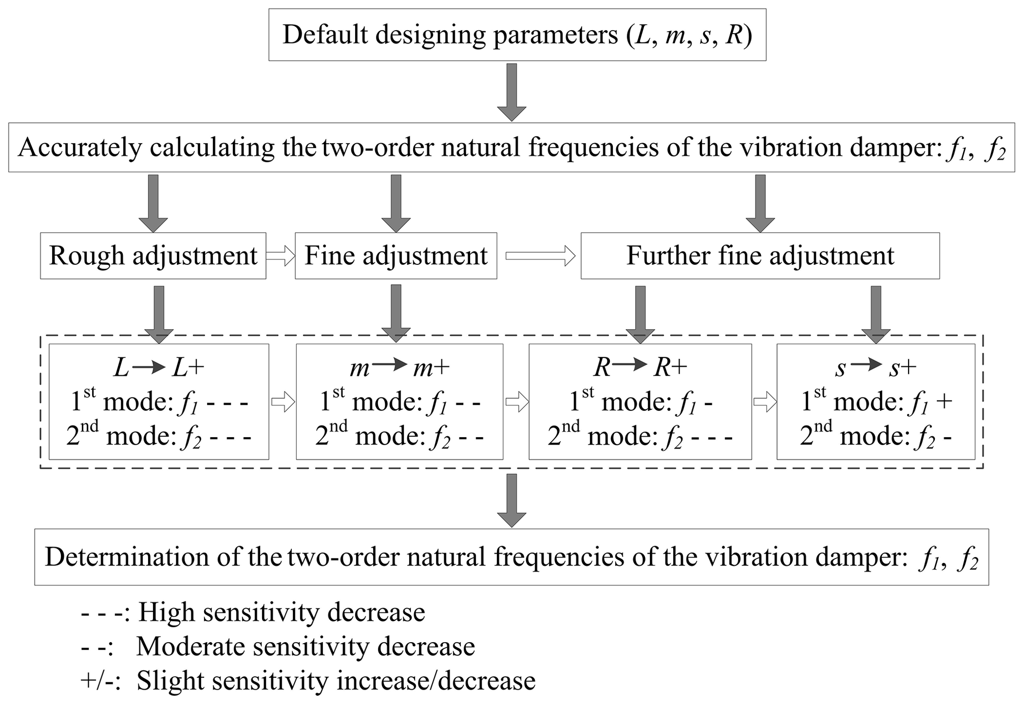
Figure 7The sensitivity of a Stockbridge type vibration damper's natural frequencies to the structural parameters, as well as the natural frequencies design process of a Stockbridge type vibration damper to obtain the target natural frequencies.
In reality, parameters s and R, i.e. the eccentric distance and the radius of gyration of the counterweight, remain unchanged when the geometrical shape of the counterweight is specific. And the mass of the counterweight is also affected by the geometrical shape; however, the mass is also affected by the material which is used to make the counterweight. As mentioned in Sect. 3.2, there are correlations among parameters m, s, and R, meaning that the variation of one parameter alone will cause the change of the other two parameters. Only the length of the steel strand, i.e. L, is independent of other parameters. This brings complexity to the structural design of a vibration damper. Figure 7 shows the sensitivity of a Stockbridge type vibration damper's natural frequencies to the structural parameters and the natural frequencies design process of a Stockbridge type vibration damper to obtain the target natural frequencies. Obviously, within the range of parameters used in this paper, the two frequencies are highly sensitive to the length of the steel strand, and this parameter is independent. As a consequence, when designing the structure parameters of a Stockbridge type vibration damper to obtain the target natural frequencies, adjusting the length of the steel strand is preferred at first, and frequencies close to the target natural frequencies can be obtained quickly. It is called coarse adjustment. The geometrical shape of the counterweight is then designed to obtain proper quality, eccentric distance, and radius of gyration. Since the first-order frequency has the positive sensitivity and the second-order frequency has the negative sensitivity, the “gap” of the two frequencies can be adjusted by changing parameter s. However, several adjustments may need to make the designing frequencies close enough to the target frequencies.
-
The approximate calculation formulas of natural frequencies of the one-side subsystem of the Stockbridge type vibration damper were derived. The calculation formulas are the same as the formulas calculated with equivalent stiffness and equivalent mass (moment of inertia).
-
The exact calculation and approximate calculation results of the natural frequencies of the vibration damper's one-side subsystem indicate the following: when the length of the steel strand, the mass of the counterweight, the eccentric distance, and the radius of gyration of the counterweight vary in the range of ±30 %, the first-order frequency obtained by approximate calculation is lower than exact calculation results, whereas the second-order frequency obtained by approximate calculation is larger than exact calculation results; with the exception that the parameters are not included in the approximate calculation formulas, the variation trend of the approximately calculated values and the exact calculated values of the frequency are consistent. Besides, only the calculation errors caused by the mass of the counterweight remain the same and the errors are related to the other three structure parameters.
-
Within the range of the parameters used in this study, the first-order frequency is highly sensitive to the length of the steel strand, whereas it is moderately sensitive to the mass of the counterweight and slightly sensitive to the eccentric distance and the radius of gyration of the counterweight. Furthermore, the first-order frequency is slightly more sensitive to the radius of gyration than the eccentric distance, and it is negatively sensitive to the eccentric distance. The second-order frequency is highly sensitive to the length of the steel strand and the radius of gyration of the counterweight, moderately sensitive to the mass of the counterweight, and slightly sensitive to the eccentric distance. Besides, the sensitivity to the length of the steel strand is slightly higher than that to the radius of gyration, and the second-order frequency is positively sensitive to all the structure parameters.
-
Within the range of the parameters used in this study, the first-order frequency is more sensitive to the length of the steel strand than the second-order frequency; sensitivity of the two frequencies to the mass of the counterweight is the same; the first-order frequency has the positive sensitivity, and the second-order frequency has the negative sensitivity to the eccentric distance; the second-order frequency is more sensitive to the radius of gyration of the counterweight than the first-order frequency.
All the data used in this paper can be obtained upon request from the corresponding author.
QY wrote the original draft and conducted the investigation; JZ provided the financial support and the damper model and collected the experimental data; YL created the models, conducted the investigation, analysed the data mathematical, and reviewed, edited and revised the manuscript; YZ put forward the research idea and led and managed the research activity.
The authors declare that they have no conflict of interest.
Publisher's note: Copernicus Publications remains neutral with regard to jurisdictional claims in published maps and institutional affiliations.
This research has been supported by the project “Research on wind-induced vibration control technology of Transmission Lines in Typical Wind-induced vibration region of Inner Mongolia Power Grid” (grant no. 2020-042).
This paper was edited by Daniel Condurache and reviewed by Petr Chalupa and two anonymous referees.
Barbieri, N. and Barbieri, R.: Dynamic analysis of Stockbridge damper, Advances in Acoustics and Vibration, 2012, 659398, https://doi.org/10.1155/2012/659398, 2012.
Barbieri, N., Barbieri, R., da Silva, R. A., Mannala, M. J., and de Sant'Anna Vitor Barbieri, L.: Nonlinear dynamic analysis of wire-rope isolator and Stockbridge damper, Nonlinear Dynam., 86, 501–512, https://doi.org/10.1007/s11071-016-2903-1, 2016.
Barbieri, N., Marchi, M. E., Mannala, M. J., Barbieri, R., Barbieri, L. de S. V., and de Sant'Anna Vitor Barbieri, G.: Nonlinear dynamic analysis of a Stockbridge damper, Can. J. Civil Eng., 46, 828–835, https://doi.org/10.1139/cjce-2018-0502, 2019.
Barry, O., Oguamanam, D. C. D., and Lin, D. C.: Aeolian vibration of a single conductor with a Stockbridge damper, P. I. Mech. Eng. C-J. Mec., 227, 935–945, https://doi.org/10.1177/0954406212452064, 2012.
Barry, O., Zu, J. W., and Oguamanam, D. C. D.: Nonlinear dynamics of Stockbridge dampers, J. Dyn. Syst-T. ASME, 137, 061017, https://doi.org/10.1115/1.4029526, 2015.
Bukhari, M. A. and Barry, O. R.: Nonlinear vibrations analysis of overhead power lines: a beam with mass-spring-damper-mass systems, J. Vib. Acoust., 140, 031004, https://doi.org/10.1115/1.4038807, 2018.
Bukhari, M. A., Barry, O., and Tanbour, E.: On the vibration analysis of power lines with moving dampers, J. Vib. Control, 24, 4096–4109, https://doi.org/10.1177/1077546317719194, 2018.
Claren, R. and Diana, G.: Mathematical analysis of transmission line vibration, IEEE T. Power Ap. Syst., PAS-88, 1741–1771, 1969.
Dutkiewicz, M. and Machado, M. R.: Measurements in situ and spectral analysis of wind flow effects on overhead transmission lines, Sound Vib., 53, 161–175, https://doi.org/10.32604/sv.2019.04803, 2019.
Foti, F. and Martinelli, L.: Hysteretic behaviour of Stockbridge dampers: modelling and parameter identification, Math. Probl. Eng., 2018, 8925121, https://doi.org/10.1155/2018/8925121, 2018.
Kim, C.: Design sensitivity analysis of a Stockbridge damper to control resonant frequencies, J. Mech. Sci. Technol., 31, 4145–4150, https://doi.org/10.1007/s12206-017-0810-0, 2017.
Langlois, S. and Legeron, F.: Prediction of aeolian vibration on transmission line conductors using a nonlinear time history model – Part I: Damper model, IEEE T. Power Deliver., 29, 1168–1175, https://doi.org/10.1109/TPWRD.2013.2291361, 2014.
Leblond, A. and Hardy, C.: On the estimation of a 2×2 complex stiffness matrix of symmetric stockbridge-type dampers, 3rd Int. Symp. Cable Dynamics, Norway, 1999.
Li, L., Zhang, Z. Y., Xu, N. B., and Yi, Y. Z.: Theoretical calculation model and tests for FDZ-type dampers (in Chinese), Journal of Vibration and Shock, 37, 196–203, 2018.
Luo, X., Wang, L., and Zhang, Y.: Nonlinear numerical model with contact for Stockbridge vibration damper and experimental validation, J. Vib. Control, 22, 1217–1227, https://doi.org/10.1177/1077546314535647, 2016.
Qi, Y., Rui, X., Ji, K., Liu, C., and Zhou, C.: Study on aeolian vibration suppression schemes for large crossing span of ultra-high-voltage eight-bundle conductors, Adv. Mech. Eng., 11, 1–12, https://doi.org/10.1177/1687814019842706, 2019.
Sauter, D. and Hagedorn, P.: On the hysteresis of wire cables in Stockbridge dampers, Int. J. Nonlin. Mech., 37, 1453–1459, https://doi.org/10.1016/S0020-7462(02)00028-8, 2002.
Shao, T.: Mechanical calculation of overhead transmission lines (in Chinese), 2nd edition, China electric power press, Beijing, China, 2003.
Si, J., Rui, X., Bin, L., Zhou, L., and Liu, S.: Development of a wind spoiler anti-galloping device for bundle conductors of UHV overhead transmission lines, IEEE T. Power Deliver., 35, 1348–1356, https://doi.org/10.1109/TPWRD.2019.2943383, 2020.
Stockbridge, G. H.: Vibration damper, U.S. Patent, no. 1675391, 1928.
Vaja, N. K., Barry, O. R., and Tanbour, E. Y.: On the modeling and analysis of a vibration absorber for overhead powerlines with multiple resonant frequencies, Eng. Struct., 175, 711–720, https://doi.org/10.1016/j.engstruct.2018.08.051, 2018.
Wagner, H., Ramamurti, V., Sastry, R. V. R., and Hartmann K.: Dynamics of stockbridge dampers, Sound Vib., 30, 207–220, https://doi.org/10.1016/S0022-460X(73)80114-2, 1973.
Wang, Z. S., Li, H. N., and Song, G. B.: Aeolian Vibration Control of Power Transmission Line Using Stockbridge Type Dampers – A Review, Int. J. Struct. Stab. Dy., 21, 2130001, https://doi.org/10.1142/S0219455421300019, 2021.
Zhan, X., Qin, Z., Chen, Y., and Liu, S.: Research on the power and anti-vibration characteristics of damper, in: Proceedings of the 2011 IEEE Power Engineering and Automation Conference, Wuhan, China, 8–9 September 2011, 298–303, 2011.
- Abstract
- Introduction
- Dynamic characteristics of a Stockbridge type vibration damper
- The calculation method of the natural frequencies of a Stockbridge type vibration damper
- Natural frequencies' sensitivity to the structural parameters of the vibration damper
- Conclusions
- Data availability
- Author contributions
- Competing interests
- Disclaimer
- Financial support
- Review statement
- References