the Creative Commons Attribution 4.0 License.
the Creative Commons Attribution 4.0 License.
 | 04 Feb 2021
A modal-based balancing method for a high-speed rotor without trial weights
Yun Zhang
Meng Li
Hongzhi Yao
Yanjie Gou
Xiaoyu Wang
The unbalance-induced vibration of a high-speed rotor directly affects the manufacturing accuracy. To effectively suppress this undesired vibration and avoid the complicated process of using trial weights during the balancing adjustment, a modal-based balancing method for a high-speed rotor without trial weights is proposed. First, the matrix sweep operation is employed to acquire the unbalance equivalent plane (EP). Next, the equivalent concentration methods, using the vector feedback principle (VFP) and modal equivalent principle (MEP), respectively, are studied and compared, while the equivalent transfer of the continuous unbalance vector to the EP is realized. Then, through modal analysis and the MEP, a balancing method, without trial weights required, is proposed for the high-speed rotor, which only needs to collect vibration data below critical speed. Finally, the rotor model and the presented method are validated on a rotor test platform, where the simulation and experiment results show that the unbalance-induced vibration has been effectively suppressed, ensuring smooth and safe operation of the rotor at high speed.
- Article
(5709 KB) - Full-text XML
- BibTeX
- EndNote


High-speed rotating systems, as the driving source of cutting tools or actuators, are widely used in manufacturing equipment such as CNC machine tools (Brecher et al., 2007), and their dynamic performance directly affects the manufacturing accuracy. A high-speed rotor is the core component of a typical rotating system. Due to material anisotropy, installation eccentricity and other factors, the actual rotation axis of a rotor is usually not aligned with its geometric axis, which induces unbalance and vibration when working at high speed (Knowles et al., 2017). If the vibration exceeds a certain limit, the quality and efficiency of the rotation system will decrease, resulting in the failure of the manufactured parts. Therefore, how to suppress the unbalance-induced vibration becomes a key problem of the high-speed rotor system's application.
There are two classic methods for balancing flexible rotors (Kellenberger, 1972; Kang et al., 1996; Foiles et al., 1998; Xu et al., 2001): the influence coefficient (IC) method and the modal balancing (MB) method. Regarding the former, Zhou et al. (2004) presented an active balancing method of the rotor system during acceleration, which relies on the ICs at different speeds. Xu and Fan (2013) analysed the vibration form of a rigid rotor under unbalance inertia force: the amplitude and phase of the unbalance-induced vibration signal are obtained based on the principle of the cross-correlation method. Chu et al. (2018) introduced the system-level balancing method, where the IC approach is applied to solve the problem of excessive floor panel vibration. In the case of the MB method, Han (2007) aimed at the new generalized modal balancing for non-isotropic rotor systems, which uses the derived unbalance modal responses from the complete modal analysis. Deepthikumar et al. (2013) described the eccentricity distribution of the finite-element model by a polynomial curve and estimated the unbalance distributions based on the MB principle and the measured vibration responses; then, the rotor is balanced at its first bending critical speed. Since the above two methods have their own advantages and disadvantages, scholars try to integrate the advantages of the two methods and put forward a unified balancing method (Darlow et al., 1981; Kang et al., 1997). Khulief et al. (2014a) developed a low-speed unbalance identification method for high-speed rotors, which relies on the knowledge of the ICs and the modal characteristics of the rotor. However, these methods still need to use trial weights during the balancing process, which complicates the operation of balancing and increases the cost.
If the unbalance distribution of the rotor can be accurately identified, without the need for trial weights, the balancing process will become simple and safe. Thus, the balancing method without trial weights attracted research focus. Scholars have done a lot of work on such methods (Moton, 1985; Zhu and Wang, 1995; Xu et al., 2000; Delgado, 2002; El-Shafei et al., 2004). Ramlau and Niebsch (2009) described a new method for the detection and reconstruction of imbalances in the rotor of a wind turbine, avoiding test-weight measurements, while the wind turbine model can be used to predict the vibrations, given a specific imbalance distribution. Li et al. (2013) provided a new balancing method without trial weights for flexible rotors, which is based on the traditional MB method and combines the dynamic characteristics of the rotor. Khulief et al. (2014b) developed a hybrid experimental and analytical technique for balancing high-speed flexible rotors: this approach does not rely on trial runs and does not require one to operate the supercritical rotor in a high-speed balancing facility. Bin et al. (2014) developed a virtual dynamic balancing methodology without trial weights and have validated it by solving a shafting dynamic balancing example with no trial-weight requirements. Zhang et al. (2016) proposed a balancing method based on a virtual IC matrix for flexible rotors without trial weights, and the validity of the ICs is verified by an experiment on a rotor test rig. Wang et al. (2017) provided an efficient way, which is based on a novel measurement point vector method, for rotor balancing without test runs and external excitations, and only the measured unbalance response of the rotor shaft under steady-state operating conditions is needed. Ye et al. (2018) proposed a balancing method without trial weights by using the dynamic similitude scale model; this method could be used to directly obtain the required coefficients for the balancing problem of the prototype system through a similarity model test.
Although remarkable balancing effects are obtained by the aforementioned approaches, there are still some issues worth further study, for example the optimization of unbalance correcting planes, the balancing realization based on the low-speed data collection, and efficiency improvement of the balancing process. Moreover, in some methods, the constructed model is only used to obtain the virtual vibration IC, while the characteristics of rotor dynamics are not taken into account. Aiming to solve the problem at hand, the authors have devised a modal-based balancing method for a high-speed rotor, which makes full use of modal information of the rotor to solve and correct the continuous unbalance vector. The scientific contribution of this paper is the proposal of a non-trial-weight balancing method, which adapts to optimal selection of the equivalent correcting plane and requires one only to collect vibration data below critical speed. The paper is structured into five sections. Following the introduction, Sect. 2 includes the selection of the equivalent plane for correcting unbalance, and the equivalent transfer principle of the continuous unbalance vector to the equivalent plane is presented. Based on this, a modal-based unbalance identification method is proposed. Section 3 analyses the effectiveness of the modal equivalent principle and the proposed balancing method by numerical simulation. The experimental platform is presented in Sect. 4 along with the experimental results and discussion. Lastly, the conclusions are given in Sect. 5.
2.1 Selection of equivalent plane
In theory, the higher the number of unbalance correcting planes, the better the desired effect will be. However, when there are too many correcting planes, the condition number of the corresponding IC matrix will get higher, which eventually leads to unreasonable counterweight results. Therefore, there is always at least one group of planes, called equivalent planes (EPs), which are able to produce an equivalent excitation effect to the one derived by all the correcting planes. The matrix sweep operation (MSO) can be used to obtain EPs in the unbalance problem. Suppose is a diagonal element in , aii≠0, the MSO process from matrix A to B with aii as the pivot element can be expressed as , and each element in matrix B can be expressed as
If the maximum value of aii is not less than the preset threshold value μ, the correcting planes described in matrix A can be analysed successively through the MSO with the maximum value as the pivot element. In this process, the correcting plane with the smallest multicollinearity corresponding to the maximum value will always be selected first, while the plane with strong multicollinearity will be excluded so as to achieve obtaining of the EPs. Based on this principle, suppose H is the subscript set of diagonal elements after the MSO, while P is the set of other subscript elements. A represents the matrix of ICs between different correcting planes and unbalance vectors. The threshold value is considered to be , where σ is the standard deviation and W is the maximum correction mass that can be applied. The basic steps to derive the EPs of unbalance-correcting planes based on the MSO are as follows.
-
The values are initiated: , A(0)=ATA; find i1∈P(0) so that ; if , continue to step 1; otherwise, the algorithm ends, while the EP does not exist.
-
In step k, , (, the subscript set is updated: , ; find so that ; if and , continue to the step k+1 until ; then, the algorithm ends, while the planes corresponding to the elements in set H are EPs.
Based on the obtained EPs, the continuous unbalance vector can be corrected using the traditional IC balancing method, which can be expressed as
where is the counterweight vector on K correcting planes, is the vibration response on J measuring planes, and A is the IC matrix between the vibration response and the unbalance vector.
If K≤J, Eq. (2) has a unique solution or an optimized solution, and the continuous unbalance vector is directly corrected with a finite number of correcting planes, which can be called the vector feedback principle (VFP). Based on this, the continuous unbalance vector is equivalently transferred to the EP, producing the continuous unbalance correction without solving the unbalance forces on all nodes. However, the VFP does not consider the modal characteristics of the rotor, while its dynamic balance effect will be difficult to maintain near the critical speed. Therefore, it is necessary to analyse the equivalent principle of the unbalance vector from the perspective of the modal shape.
2.2 Modal equivalent principle
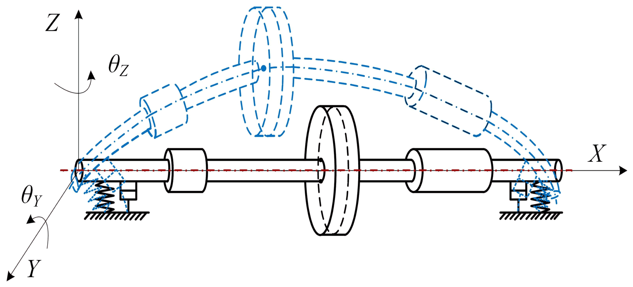
As shown in Fig. 1, the dynamics model of the rotor-bearing system can be divided into two parts, the finite-element model of the rotor and the one of the journal-bearing restraint. It is assumed that the FE model has N nodes, while the N−1 shaft segments can be assembled by using the common finite-element procedure (Cao and Altintas, 2005; Zou et al., 2019). The radial displacement and rotation of a single element, in the generalized coordinate system, can be expressed as , (), where yn and zn are the displacements of the y and z axes, respectively, while and are the rotation angles of the y and z axes, respectively.
The dynamic differential equation of the rotor is described as
where M is the system mass matrix, , K is the system stiffness matrix, , and C is the system damping and gyroscopic matrix, . Fu represents the unbalance force and is defined as , . Fb represents the oil film force and is defined as , , where and are the components of the oil film force (Capone, 1991; Xie et al., 2021) in the y and z directions, respectively.
The main vibration modal shape of the ith order is expressed as , , where , , while the vibration modal shape of the rotor can be expressed as ; the unbalance response δ on the measuring planes can be converted to ξ in modal coordinates:
where , , ξ and η are the components of the deflection on the ζ−x and η−x planes, respectively.
By substituting Eq. (4) into Eq. (3) and multiplying both sides of the equation by ΦT, the dynamic differential equation of the rotor becomes
Due to the orthogonality of each vibration modal shape, , and are diagonal matrices, while the elements on the diagonal are , and . Similarly, the N order modal unbalance force can be expressed as , where . Therefore, Eq. (5) can be written as
where , , , and .
Assuming that the particular solution of the vibration response is ξ=ξ0ejΩt and that is the simple harmonic excitation, then Eq. (6) can be written as
The deflection of the unbalanced rotor can be expressed as
where cr represents the component of the rth modal shape in εu(x), αr represents the phase of this component, ϕr(x) is the modal shape, while the subscript r represents the order; is the correcting coefficient.
To make the concentrated force loaded on the EP equivalent to the distributed unbalanced force on the rotor, the vibrations generated by the two should be equal. Assuming that the equivalent concentrated force on EP is p(xk) (), the following equation needs to be established:
where , represents the mechanical lag angle and ζ represents the modal damping coefficient, which is derived by experiment or obtained by a proportional relation to stiffness and mass.
Then, the equivalent balancing equation can be derived from Eq. (9):
According to Eq. (10), the continuous unbalance vector distribution on the rotor can be equivalently concentrated, without changing the vibration characteristics of the rotor, as long as the modal unbalance force on the rotor remains constant, which can be called the modal equivalent principle (MEP). Since a small unbalance force at low speed cannot excite the vibration modal shape of the rotor, the MEP is more applicable to high-speed rotor operation.
2.3 Modal-based unbalance identification method
In the above analysis, the continuous distributed unbalance vector can be equivalently concentrated to EP, according to the MEP. Based on this fact, the modal-based unbalance identification method is presented in this section. Given the unbalance response analysis in Eq. (3), it can be concluded that the maximum relativity between the vibration response and unbalance vector takes place along the radial direction. Hence, the radial motion alone is used as the balancing target in the following approach. Assuming that the unbalance masses are distributed on U nodes, while only J(J≤N) measuring planes and K(K≤N) correcting planes are used to eliminate the unbalance force. The vibration response and the unbalance force are transformed between physical and modal coordinates according to the following:
where , is a sub-vector of the vibration modal shape with J measuring planes, is the response in modal coordinates, , is a sub-vector of the vibration modal shape with U unbalanced nodes, is the unbalance force distributed on U nodes, and is the unbalance force of the first n order modes in modal coordinates.
Due to the limitation of the measurement planes and the uncertainty of the unbalance nodes, the ΦJ and may not necessarily be of full rank. Therefore, Eq. (11) should be transformed into the following form:
Substituting Eq. (12) into the Fourier-transformed form of Eq. (6) leads to the following:
Next, substituting Eq. (14) into Eq. (13) provides the following:
According to the analysis of the MEP, the unbalance vector distribution on the rotor can be corrected by the counterweights W added on the EP, as long as the following modal equivalence relation is satisfied.
where , is a sub-vector of the vibration modal shape with K correcting planes, and is the counterweight vector applied on the correcting planes.
By substituting Eq. (13) into Eq. (14), the counterweight vector can be obtained as
3.1 Unbalance equivalent
To verify the equivalent method of the unbalance force, the finite-element model of the rotor system, consisting of 50 elements and 51 nodes, is established, corresponding to Fig. 2. The mass disk units, which can be used as correcting planes, are located at the 11th, 18th, 23rd, 29th, 34th and 41st nodes, the measuring planes are located at the 15th and 37th nodes, while the journal-bearing units are located at the 5th and 47th nodes.

The MSO analysis of the model, as illustrated in Fig. 2, shows that the third and fifth disks are EPs, while the rest of the planes are redundant ones. The relationship between EPs and other planes is as follows:
where α represents the IC and the subscript represents the respective correcting plane.
In order to prove the validity of EPs, the relationship between the left- and right-hand sides, in Eq. (18), is determined at 2400, 3200 and 4000 r/min, respectively, while comparison of the findings follows. Since there are two measuring planes used to collect vibration information, each disk can obtain six ICs, which are then verified. Figure 3 shows that the results obtained by both sides of Eq. (18) are identical; that is to say, the effect of the first, second, fourth and sixth disks on the vibration characteristics of the rotor can be completely replaced by that of the third and fifth disks, proving the existence of EPs.

Figure 3The relationship between EPs and redundant planes. (a) Disk 1. (b) Disk 2. (c) Disk 4. (d) Disk 6.
To verify the effectiveness of the equivalent principle on the EP for dynamic balancing, the distributed unbalance vectors in redundant planes are equivalent to EPs, according to the VFP and MEP, respectively, while the unbalance response characteristics, before and after equivalent operation, are compared and analysed. Here, the vibration response is obtained based on the rotor model, as shown in Fig. 2 at 3400 r/min, while the unbalance vectors on the first, second, fourth and sixth disks are, respectively, equivalent to the ones on the third and fifth disks. The details of equivalent results are listed in Table 1, while the comparison of unbalance responses after equivalence of disks, based on the VFP and MEP, is shown in Fig. 4.


Figure 4Comparison of unbalance response after equivalence of disks based on the VFP and MEP. (a) Left-hand side on the first disk. (b) Right-hand side on the first disk. (c) Left-hand side on the second disk. (d) Right-hand side on the second disk. (e) Left-hand side on the fourth disk. (f) Right-hand side on the fourth disk. (g) Left-hand side on the sixth disk. (h) Right-hand side on the sixth disk.
As shown in Fig. 4, if the unbalance vector on a redundant disk is transferred to the third and fifth disks using the MEP, the rotor unbalance response is consistent with the initial state, within the full speed range. However, if the VFP is employed to implement the equivalent transfer operation, the unbalance response is only consistent with the initial state, at around 3400 r/min, while the variation of the two response curves becomes obvious, at a different speed value. This phenomenon is due to the fact that the VFP does not consider the influence of the rotor modal shape, while rotor vibration is essentially the superposition of the multiple-modal vibrations excited by the unbalance. If the distributed unbalanced vector is directly transferred to the EP through the VFP, the obtained equivalent result does not consider the modal characteristics. When the rotor speed changes, the current balance effect cannot be maintained. As a result, the MEP is more suitable than the VFP for dynamic balancing of high-speed rotors.
3.2 Dynamic balancing
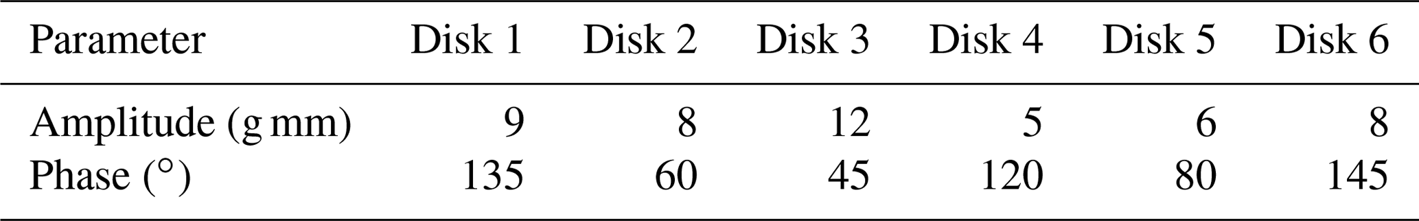
In order to verify the effectiveness of the proposed unbalance identification method, based on the EP and MEP, numerical simulation of dynamic balancing is performed on the rotor model (Fig. 2). The virtual initial unbalance, as shown in Table 2, is artificially applied on the six disks of the rotor.
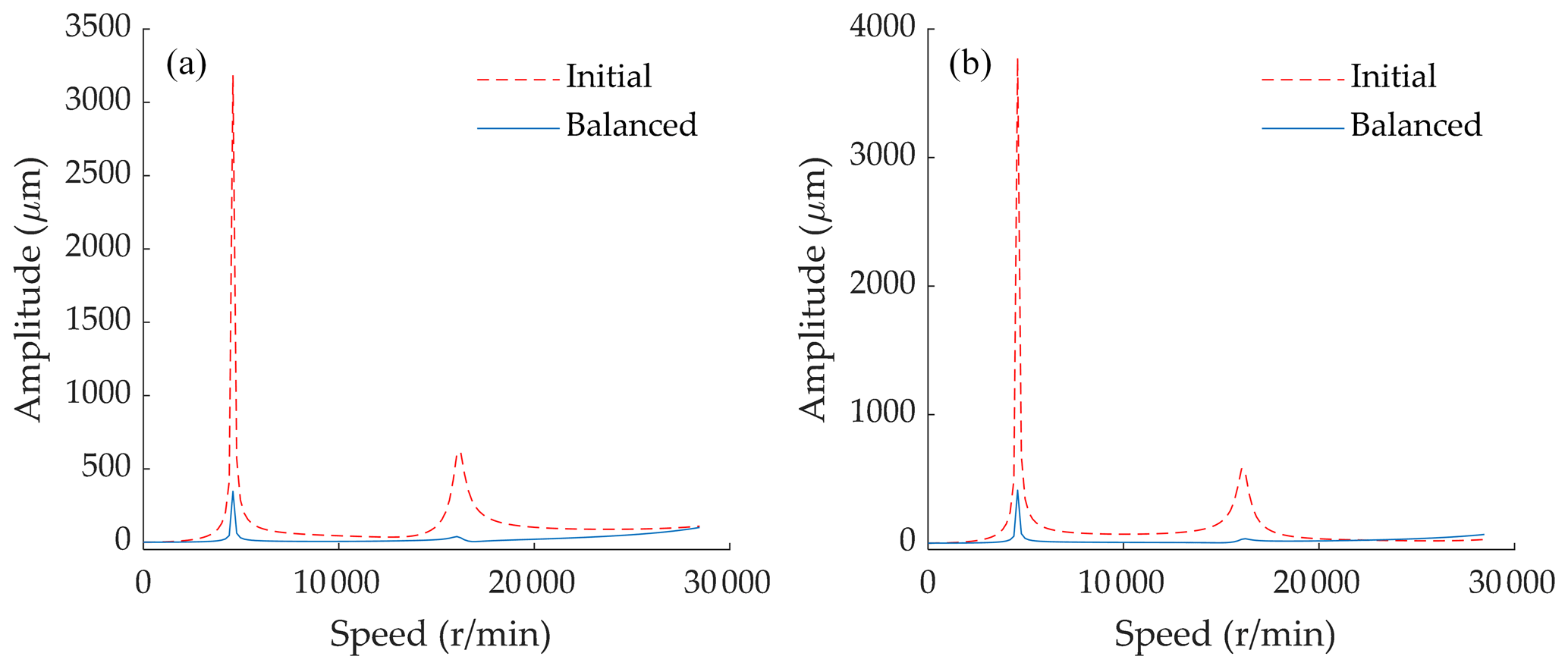
Figure 5Comparison of unbalance response before and after the balancing procedure. (a) Left-hand side. (b) Right-hand side.
The balancing speed is set at 3400 r/min, and the counterweights on the third and fifth disks can be calculated by Eq. (17), as 24.33 g mm at 244.51∘ and 7.22 g mm at 297.39∘. Next, in order to suppress the unbalance response at the measuring planes, the identified counterweights are substituted into the rotor model. The unbalance response before and after the balancing procedure is illustrated in Fig. 5.
As illustrated in Fig. 5, the comparative results show that the proposed method can effectively identify the unbalance vector. After the balancing procedure, the residual vibration below and beyond the critical speed is very small, which demonstrates the effectiveness of the method.
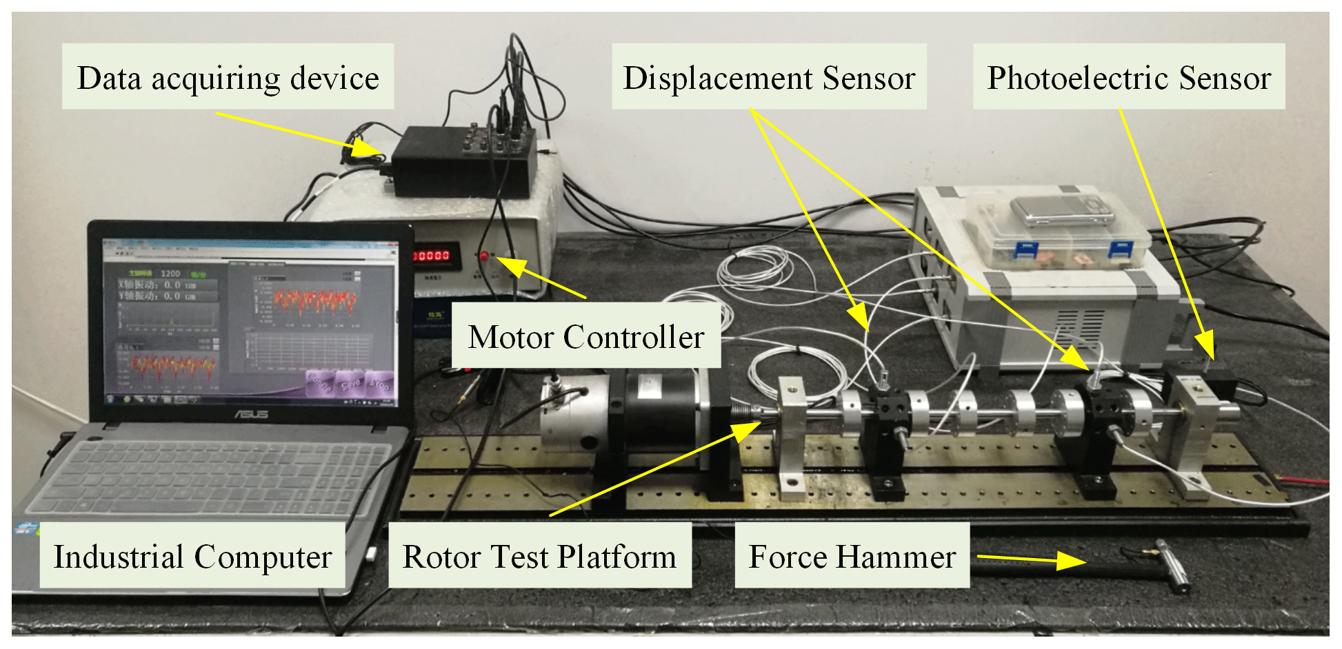
To verify the validity of the proposed rotor model and unbalance identification method, an experimental platform, consistent with Fig. 2, is designed and built (Fig. 6). This system consists of a data acquiring and processing device, phase and displacement sensors, a force hammer and a motor controller. The phase and displacement sensors are fixed on the support setting along the radial direction, while the output analog signals, generated by sensors, are transformed into digital signals by the data acquisition device and collected by an industrial computer which processes and displays vibration information. The rotor is connected to the motor via a flexible coupling, the weight of the mass disk assembled on the rotor is 0.08 kg, while 10 evenly distributed holes are available for adding counterweights on the disk. The rotor length is 500 mm and its nominal diameter and the mass disk are 10 and 50 mm, respectively. The rotor and the mass disks are made of steel and aluminium, respectively. The density of the rotor material is 7800 kg/m3, the elastic modulus is 3.15×10¹¹ N/m2 and the Poisson ratio is 0.3.
4.1 Model verification
In modal test, an impact excitation, generated by an impulse force hammer with a model of LC-01A, is applied on the rotor, while the response signal is acquired by an acceleration sensor with a model of ULT2001. Both the excitation and response signals are collected by the data acquisition device NI-9220 at a sampling frequency of 15 kHz. The measured excitation and response signal are illustrated in Fig. 7, while the simulated and measured frequency response functions (FRFs) of the rotor are shown in Fig. 8.
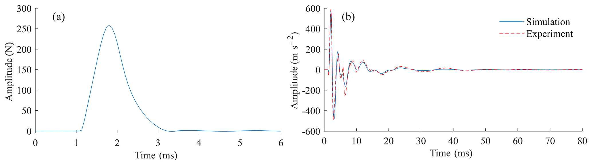
Figure 7The excitation and responses signal on the rotor. (a) The measured excitation force. (b) The response signal.
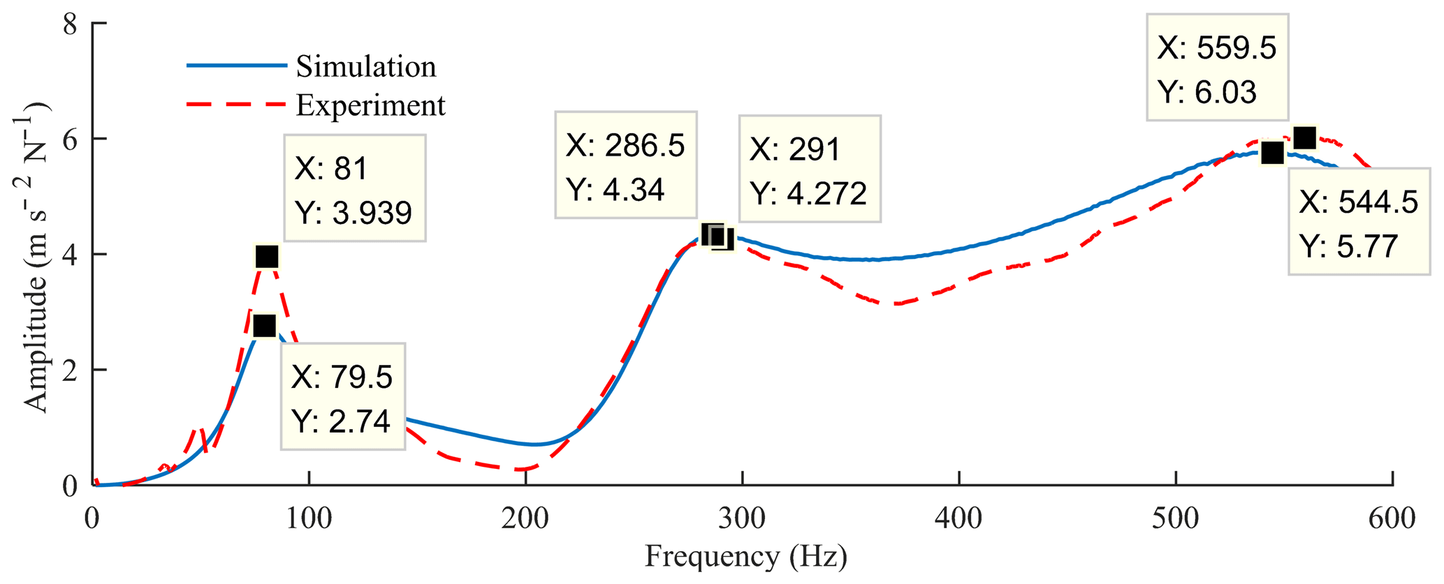
According to Figs. 7 and 8, the simulated and experimentally measured FRFs are in reasonable agreement. In the simulated FRFs, the first three natural frequencies have been found to be 79.5, 286.5 and 544.5 Hz. Meanwhile, the first three natural frequencies, as obtained by the measured FRFs, are 81, 291 and 559.5 Hz. The deviation between simulation and experiment of the first three order modes is 1.9 %, 1.5 % and 2.6 %, respectively, indicating the high accuracy of the model.
4.2 Balancing effect verification
To verify the effectiveness of the presented unbalance method, the balancing experiments are performed on the experimental platform shown in Fig. 6. The eddy current displacement sensor WD502A and the photoelectric sensor E3X-HD41 are used to collect the amplitude and phase of unbalanced vibration, respectively. In order to be consistent with the simulation conditions as much as possible, the balancing speed is set to 3400 r/min, and the sampling frequency is set to 10 kHz. According to Eq. (17), the identified counterweights on the third and fifth disks are 15.92 g mm at 250.70∘ and 7.22 g mm at 69.47∘, respectively.
Table 3The comparison of unbalance vibration before and after adding counterweights.

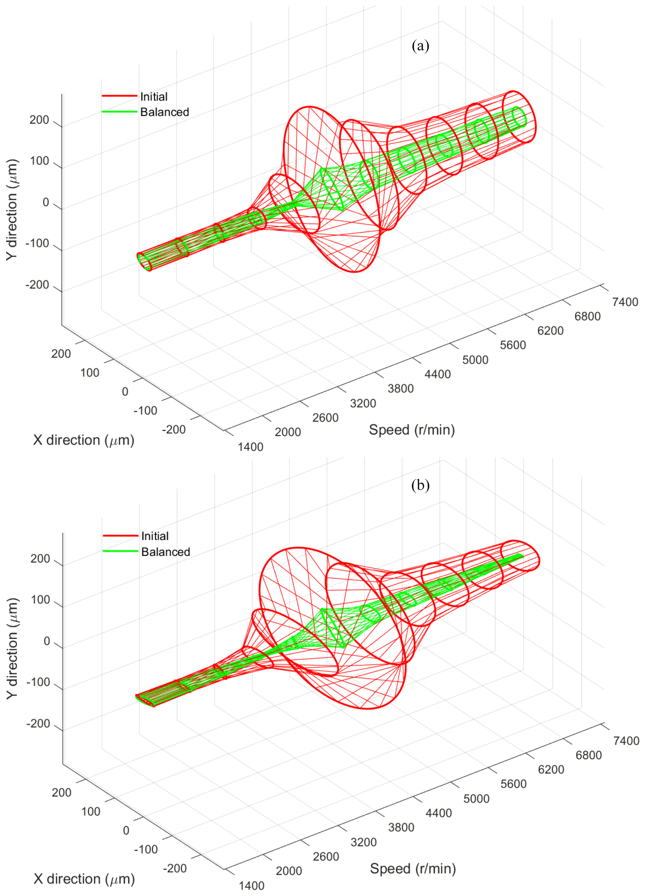
Figure 9The initial and residual vibration after applying the proposed method. (a) Left-hand side. (b) Right-hand side.
After completing the counterweight vector identification, the identified results need to be added on the corresponding mass disks to suppress the unbalance vibration. Since there are 10 evenly distributed holes on the third and fifth disks for adding counterweight screws, and the weight of the counterweight screws is limited to certain values, the identified counterweight vector needs to be decomposed into different holes of the disks. In this specific case, in order to realize the correction process, 0.5 and 0.8 g screws are added to the fifth and eighth holes of the third disk, respectively, while 0.9 g and 0.5 g screws are added to the first and fifth holes of the fifth disk, respectively.
In order to observe the change in the axis orbit along with radial direction before and after the balancing procedure, the three-dimensional holospectrum vibration in the full speed range on the measuring plane is illustrated in Fig. 9. The outer (red) curve represents the initial vibration and the inner (green) curve is the residual vibration after the balancing procedure.
As shown in Fig. 9 and Table 3, the system can operate smoothly through the first critical speed, while the unbalance vibration is significantly reduced even in the full speed range. The comparison between the initial vibration and the residual vibration shows that the proposed unbalance identification procedure is effective, and the counterweight vector, as identified by the dynamics model and the proposed method, is accurate.
It can be seen that the residual unbalance response is not completely suppressed after the balancing operation. The possible error sources are as follows: first, the rotor platform manufacturing and assembly accuracy limit the dynamic balancing effect. In the presented case, there is a specific initial bending of the experimental rotor: since both bending-induced vibration and unbalanced vibration present the same rotating-frequency characteristics, the bending-induced vibration will be regarded as unbalanced vibration in the unbalance identification process, which leads to some fake balancing operations during the experiment. Second, the accuracy of the dynamic model needs to be further improved. There are still differences between the model-based vibration modal data and the actual rotor state. Finally, the balancing quality is affected by other factors, such as the accuracy of data collection and the robustness of the rotor system.
In addition, when the speed is lower than 3800 r/min, the residual unbalance response becomes larger as the speed decreases. This phenomenon can be explained as follows: the rotor vibration is the result of the combined action of fault factors such as bending, unbalance, electromagnetic interference, and both the mechanical and electrical run-out, among others. The unbalance vibration only accounts for a lesser share of the overall vibration at the lower speed, and the vibration response is mainly caused by non-unbalance factors. This explains why the residual response at low speed in Fig. 9 is higher than that at 3800 r/min after dynamic balancing.
In order to tackle the unbalance problem, a modal-based balancing method for a high-speed rotor without trial weights is proposed. The effectiveness of the proposed method is verified by using an experimental rotor platform. Based on the results, the following conclusions are derived.
-
The EP obtained by the MSO can replace the excitation effect of all the correcting planes, and then the distributed unbalanced vector can be equivalently concentrated on the EP through the MEP, without changing the rotor modal characteristics.
-
A modal-based unbalance identification method for a high-speed rotor is proposed by using modal analysis and the MEP, which only needs to collect vibration data below critical speed and does not need to add trial weights in the balancing process.
-
The effectiveness of the proposed balancing method is validated by numerical simulation and field experiment. The results show that the proposed method can suppress the unbalance vibration effectively while ensuring smooth and safe operation of the rotor at high speed.
Although this method demonstrates a good balancing effect, there are many factors in the industrial application that can influence the result, such as the validity of vibration data or the accuracy of the dynamic model. These are issues in need of further research to obtain better results. To this end, signal-processing methods should be introduced to eliminate the interference of other faults with the same unbalance frequency characteristics, such as the form error of the measurement section, electromagnetic interference, material anisotropy, or bending. Furthermore, the accuracy of the dynamic model can also be improved by combining theory with experiment.
All data included in this study are available upon reasonable request by contacting the corresponding author.
YZ and ML designed the conceptualization, methodology and formal analysis. YZ, ML and XW performed data acquisition and validation. YZ, ML, HY and YG prepared the original manuscript. YZ and HY revised the manuscript.
The authors declare that they have no conflict of interest.
This article is part of the special issue “Robotics and advanced manufacturing”. It is not associated with a conference.
This research was funded by the National Natural Science Foundation of China, grant no. 52075408, the National Key Research and Development Program of China, grant no. 2016YFB1102502, and the Key Research and Development Program in Shaanxi Province of China, grant no. 2020ZDLGY14-05.
This paper was edited by Haiyang Li and reviewed by two anonymous referees.
Bin, G., Li, X., Wu, J., and Gao, J.: Virtual dynamic balancing method without trial weights for multi-rotor series shafting based on finite element model analysis, J. Renew Sustain. Ener., 6, 42014, https://doi.org/10.1063/1.4893911, 2014.
Brecher, C., Spachtholz, G., and Paepenmuller, F.: Developments for High Performance Machine Tool Spindles, CIRP Ann-Manuf. Techn., 56, 395–399, https://doi.org/10.1016/j.cirp.2007.05.092, 2007.
Cao, Y. and Altintas, Y.: A General Method for the Modeling of Spindle-Bearing Systems, J. Mech. Design, 126, 1089–1104, https://doi.org/10.1115/1.1802311, 2005.
Capone, G.: Analytical description of fluid-dynamic force field in cylindrical journal bearing, L'Energia Elettrica, 3, 105–110, 1991.
Chu, Z., Huang, D., and Yang, L.: Field balancing of vehicle transmission shaft based on the influence coefficient method, Noise and Vibration Worldwide, 49, 266–271, https://doi.org/10.1177/0957456518796848, 2018.
Darlow, M. S., Smalley, A. J., and Parkison, A. G.: Demonstration of a Unified Approach to the Balancing of Flexible Rotors, J. Eng. Gas Turb. Power T. ASME, 103, 101–107, https://doi.org/10.1115/1.3230679, 1981.
Deepthikumar, M. B., Sekhar, A. S., and Srikanthan, M. R.: Modal balancing of flexible rotors with bow and distributed unbalance, J. Sound Vib., 332, 6216–6233, https://doi.org/10.1016/j.jsv.2013.04.043, 2013.
Delgado, E. P.: Balancing of an experimental rotor without trial runs, International Journal of Rotating Machinery, 8, 99–108, https://doi.org/10.1155/S1023621X02000106, 2002.
El-Shafei, A., El-Kabbany, A. S., and Younan, A. A.: Rotor Balancing Without Trial Weights, J. Eng. Gas Turb. Power T. ASME, 126, 604–609, https://doi.org/10.1115/1.1762903, 2004.
Foiles, W. C., Allaire, P. E., and Gunter, E. J.: Review of Rotor balancing, Shock Vib., 5, 325–336, https://doi.org/10.1155/1998/648518, 1998.
Han, D. J.: Generalized modal balancing for non-isotropic rotor systems, Mech. Syst. Signal Pr., 21, 2137–2160, https://doi.org/10.1016/j.ymssp.2006.09.004, 2007.
Kang, Y., Liu, C. P., and Sheen, G. J.: A modified influence coefficient method for balancing unsymmetrical rotor-bearing systems, J. Sound Vib., 194, 199–218, https://doi.org/10.1006/jsvi.1996.0353, 1996.
Kang, Y., Sheen, G. J., and Wang, S. M.: Development and Modification of a Unified Balancing Method for Unsymmetrical Rotor-Bearing Systems, J. Sound Vib., 199, 349–369, https://doi.org/10.1006/jsvi.1996.0652, 1997.
Kellenberger, W.: Should a Flexible Rotor Be Balanced in N or (N plus 2) Planes, J. Eng. Industry T. ASME, 94, 558–560, https://doi.org/10.1115/1.3428190, 1972.
Khulief, Y. A., Oke, W., and Mohiuddin, M. A.: Modally Tuned Influence Coefficients for Low-Speed Balancing of Flexible Rotors, J. Vib. Acoust. T. ASME, 136, 24501, https://doi.org/10.1115/1.4025995, 2014a.
Khulief, Y. A., Mohiuddin, M. A., and El-Gebeily, M.: A New Method for Field-Balancing of High-Speed Flexible Rotors without Trial Weights, International Journal of Rotating Machinery, 2014, 1–11, https://doi.org/10.1155/2014/603241, 2014b.
Knowles, G., Kirk, A., Bingham, C., and Bickerton, R.: Generalised analysis of compensating balancing sleeves with experimental results from a scaled industrial turbine coupling shaft, P. I. Mech. Eng. C. J. Mec., 232, 3453–3468, https://doi.org/10.1177/0954406217737106, 2017.
Li, X. F., Zheng, L. X., and Liu, Z. X.: Balancing of flexible rotors without trial weights based on finite element modal analysis, J. Vib. Control, 19, 461–470, https://doi.org/10.1177/1077546311433916, 2013.
Moton, P. G.: Modal Balancing of Flexible Shafts without Trial Weights, P. I. Mech. Eng. C. J. Mec., 199, 71–77, https://doi.org/10.1243/PIME_PROC_1985_199_093_02, 1985.
Ramlau, R. and Niebsch, J.: Imbalance Estimation Without Test Masses for Wind Turbines, J. Sol. Energ. T. ASME, 131, 1–7, https://doi.org/10.1115/1.3028042, 2009.
Wang, A., Cheng, X., Meng, G., Xia, Y., Wo, L., and Wang, Z.: Dynamic analysis and numerical experiments for balancing of the continuous single-disc and single-span rotor-bearing system, Mech. Syst. Signal. Pr., 86, 151–176, https://doi.org/10.1016/j.ymssp.2016.09.034, 2017.
Xie, Z. L., Shen, N., Zhu, W., Tian, W., and Hao, L.: Theoretical and experimental investigation on the influences of misalignment on the lubrication performances and lubrication regimes transition of water lubricated bearing, Mech. Syst. Signal. Pr., 149, 107211, https://doi.org/10.1016/j.ymssp.2020.107211, 2021.
Xu, B, G., and Qu, L. S.: A new practical modal method for rotor balancing, P. I. Mech. Eng. C. J. Mec., 215, 179–189, https://doi.org/10.1243/0954406011520607, 2001.
Xu, B. G., Qu, L. S., and Sun, R.: The optimization technique-based balancing of flexible rotors without test runs, J. Sound Vib., 238, 877–892, https://doi.org/10.1006/jsvi.2000.3107, 2000.
Xu, X. and Fan, P. P.: Rigid Rotor Dynamic Balancing by Two-Plane Correction with the Influence Coefficient Method, Appl. Mech. Mater., 365/366, 211–215, https://doi.org/10.4028/www.scientific.net/AMM.365-366.211, 2013.
Ye, R., Wang, L., Hou, X., Luo, Z., and Han, Q.: Balancing method without trial weights for rotor systems based on similitude scale model, Front Mech. Eng. Prc., 13, 571–580, https://doi.org/10.1007/s11465-018-0478-x, 2018.
Zhang, Y., Wei, Q., Zou, D., and Shao, M.: Study on the Relationship between the Imbalance Status and its Vibration Response in Balancing Method of Rotors, The 23rd International Congress on Sound and Vibration (ICSV23), Athens, Greece, 10–14 July 2016, International Institute of Acoustics and Vibrations, Athens, Greece, 2016.
Zhou, S. Y., Dyer, S. W., Shin, K. K., Shi, J. J., and Ni, J.: Extended influence coefficient method for rotor active balancing during acceleration, J. Dyn. Syst. T. ASME, 126, 219–223, https://doi.org/10.1115/1.1651533, 2004.
Zhu, X. D. and Wang, X. X.: A Method of Balancing Large-Scale Flexible Rotors without Test Runs, ASME International Gas Turbine and Aeroengine Congress and Exposition, American Society of Mechanical Engineers (ASME), Houston, USA, 1995.
Zou, D., Zhao, H., Liu, G., Ta, N., and Rao, Z.: Application of augmented Kalman filter to identify unbalance load of rotor-bearing system: Theory and experiment, J. Sound Vib., 463, 114972, https://doi.org/10.1016/j.jsv.2019.114972, 2019.