the Creative Commons Attribution 4.0 License.
the Creative Commons Attribution 4.0 License.
 | 10 Jun 2021
Design and evaluation of a novel upper limb rehabilitation robot with space training based on an end effector
Qiaoling Meng
Zongqi Jiao
Hongliu Yu
Weisheng Zhang
The target of this paper is to design a lightweight upper limb rehabilitation robot with space training based on end-effector configuration and to evaluate the performance of the proposed mechanism. In order to implement this purpose, an equivalent mechanism to the human being upper limb is proposed before the design. Then, a 4 degrees of freedom (DOF) end-effector-based upper limb rehabilitation robot configuration is designed to help stroke patients perform space rehabilitation training of the shoulder flexion/extension and adduction/abduction and elbow flexion/extension. Thereafter, its kinematical model is established together with the proposed equivalent upper limb mechanism. The Monte Carlo method is employed to establish their workspace. The results show that the overlap of the workspace between the proposed mechanism and the equivalent mechanism is 96.61 %. In addition, this paper also constructs a human–machine closed-chain mechanism to analyze the flexibility of the mechanism. According to the relative manipulability and manipulability ellipsoid, the highly flexible area of the mechanism accounts for 67.6 %, and the mechanism is far away from the singularity on the drinking trajectory. In the end, the single-joint training experiments and a drinking water training trajectory planning experiment are developed and the prototype is manufactured to verify it.
- Article
(14804 KB) - Full-text XML
- BibTeX
- EndNote


Strokes affect thousands of people around the world, and nearly half of stroke survivors suffer from upper limb defects, which makes it difficult for them to perform activities of daily living (ADL) independently. For most patients, exercise therapy has the potential to partially restore the loss of motor function (Béjot et al., 2016). Studies indicated that long-term intensive training and practice would be beneficial to the rehabilitation process of patients (Bertani et al., 2017). Robot-assisted therapy equipment can provide high-intensity, repetitive, interactive treatments for the affected upper limbs and obtain physiological data of patients, which has been increasingly used in rehabilitation training (Manna and Dubey, 2017).
The human upper limbs have a complex physiological structure. With the cooperation of multiple bones and muscles, the upper limbs are very flexible, which puts forward many requirements for the structural design of the rehabilitation robot (Pons, 2008). At present, there are mainly two types of upper limb rehabilitation robots, i.e., an end-effector-based type and an exoskeleton type. The end-effector-based-type upper limb rehabilitation robots support and pull the end of the patients through a closed-loop linkage mechanism or a series mechanism, so as to realize the rehabilitation training of the upper limb. The most representative of the robots with the closed-loop linkage mechanisms include MIT-MANUS (Hogan et al., 1992), D-SEMUL (Kikuchi et al., 2018), CASIA-ARM (Luo et al., 2019), and SepaRRo (Chang et al., 2018). They could perform plane compound training for the human shoulder and elbow joints, mainly the adduction/abduction of the shoulder and the flexion/extension of the elbow. The working mode of the robots with the series mechanism is to drive the human upper limbs through the mechanical arms, such as MIME (Lum et al., 2002) and GENTLE/s (Loureiro et al., 2003). Compared to the robots with the closed-chain linkage mechanisms, this type of robot increases the function of assisting the human shoulder joints in performing flexion and extension training, so it can drive the human upper limbs to move in three-dimensional space.
A characteristic of the end-effector-based-type upper limb rehabilitation robots is that it does need to be aligned with the physiological axes of the human joints during training, but it also means that it cannot implement accurate single-joint rehabilitation training for patients. Moreover, the structures of the end-traction robots are relatively simple, most of which are desktop type, that cause the robot's range of motion (ROM) to be limited, especially the insufficient flexion and extension training of the human shoulder.
The exoskeleton-type upper limb rehabilitation robot has a kinematic structure similar to that of the human upper limb, and it generates driving force on each joint of the patient's upper limb to drive limb rehabilitation training, such as CADEN-7 (Perry et al., 2007), Harmony (Kim and Deshpande, 2017), ARMin III (Nef et al., 2009), Co-EXos (Zhang et al., 2019), Armeo Power (Jarrase et al., 2015), and LIMPACTA (Otten et al., 2015). Compared with the end-effector-based robot, the exoskeleton robot can drive the patient's limbs to perform three-dimensional rehabilitation training, especially the large-ROM flexion/extension training of the human shoulder. In addition, the driving force of the exoskeleton directly acts on the patient's single joint, which can perform accurate single-joint training on the upper limbs. However, this feature also causes the exoskeleton to require more joints and motors, making the exoskeleton bulky and costly. Since the joint axes of the human upper limb is constantly changing during the rehabilitation exercise, the misalignment of the mechanical axes of the exoskeleton and the biological axes of the upper limb will lead to the mismatching of the movement of the exoskeleton with the upper limb, thus causing discomfort for the patients.
In this paper, a novel 4 DOF end-effector-based upper limb rehabilitation robot with space training is proposed by combining the end-effector-based-type and exoskeleton-type robot. The robot can assist the human upper limb in performing rehabilitation training of the shoulder flexion/extension and adduction/abduction and elbow flexion/extension. Different from the desktop-type end-effector-based robot, the proposed robot can provide a wide range of shoulder flexion/extension training for the human upper limb and cover the ROM of the upper limb. Through the mutual restriction of three mutually perpendicular active joints, the robot can perform single-joint and unidirectional rehabilitation training on the human upper limb.
The rest of this paper is structured as follows. In Sect. 2, we introduce the configuration design and mechanical design of a 4 DOF end-effector-based upper limb rehabilitation robot. In Sects. 3 and 4, the kinematical performance of the proposed configuration is analyzed in a global and local area. In Sect. 5, a 4 DOF end-effector-based robot is developed for upper limb rehabilitation, and the pursuit movement experiment and the multi-joint exercise test of the prototype are done to verify the dexterity of the design.
2.1 Configuration design
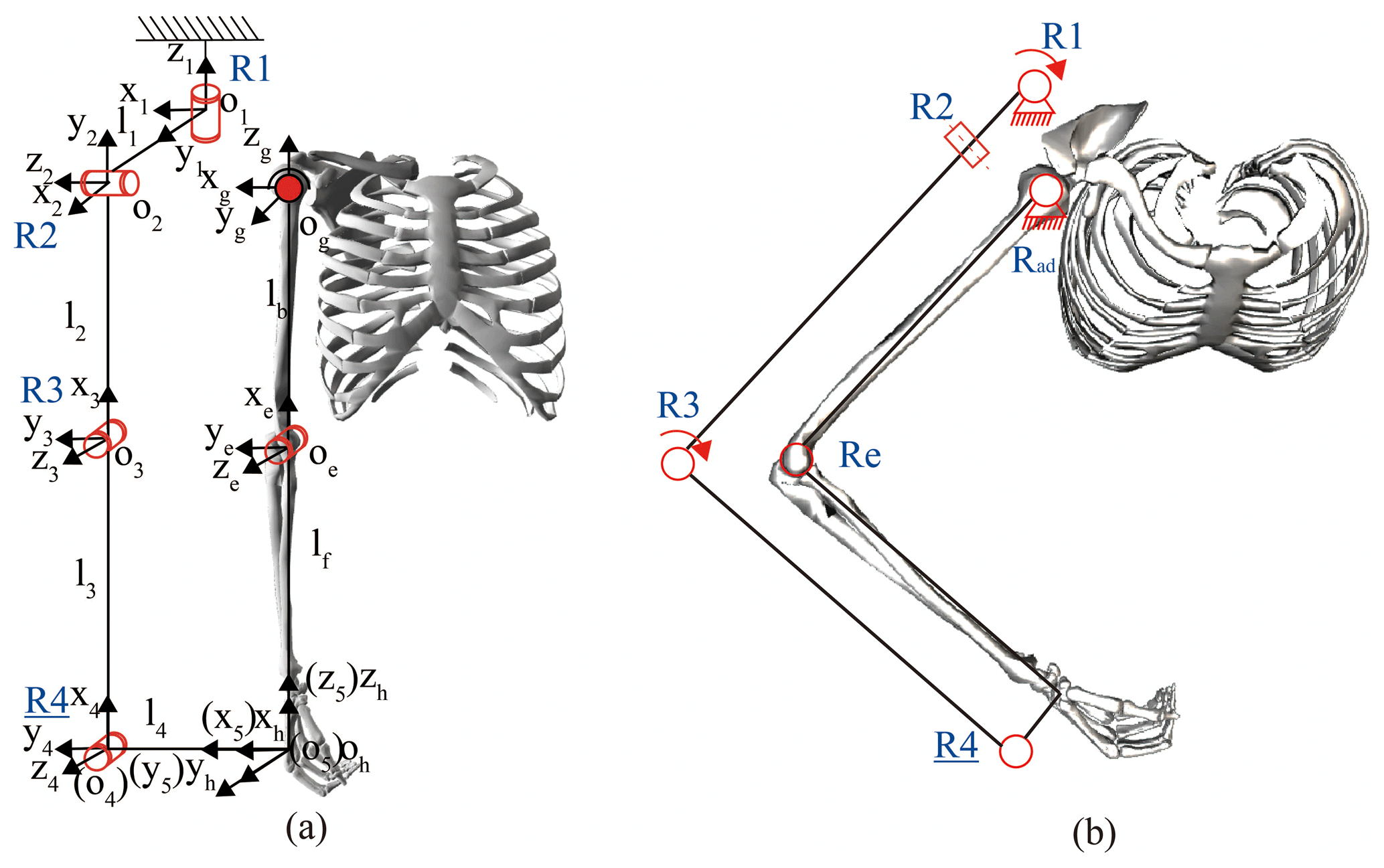
The design goal of the robot configuration is to assist the human upper limbs in performing single-joint and multi-joint rehabilitation training through end traction, including the shoulder's flexion/extension and adduction/abduction and the elbow's flexion/extension. This paper proposes a 4 DOF end-effector-based upper limb rehabilitation robot configuration, as shown in Fig. 1a. , , and are the coordinate systems of shoulder, elbow, and end point, respectively. R2 and R3 are the active joints that assist the human upper limb in performing the shoulder flexion/extension and elbow flexion/extension, respectively. R4 is a passive joint used to compensate for the nonparallel error of the robot forearm and the human forearm during the movement. The active joints R1 and R3 cooperate in helping the human upper limbs perform shoulder adduction/abduction, as shown in Fig. 1b. In this training mode, the human upper limb is combined with the robot into a five-link closed-chain mechanism in which R2 was fixed at 90∘. According to mechanism theory, the DOFs of the closed chain, F, can be calculated using Hunt's formula, which is expressed as follows:
where fi denotes the DOFs of the ith joint, l is the number of independent loops, d denotes the DOFs of the motion with which a mechanism is intended to function (for the spatial chain, d=6; for the planer chain, d=3), and n is the number of joints. It is calculated that F is 2, so the human upper limb can perform shoulder adduction/abduction training with the drive of the two active joints, R1 and R2. Since the robot drives the human upper limbs to perform rehabilitation exercises by assisting the wrist and hand, it is not necessary for the rotation axis of the robot to coincide with the physiological axes of the human.
2.2 Mechanical design
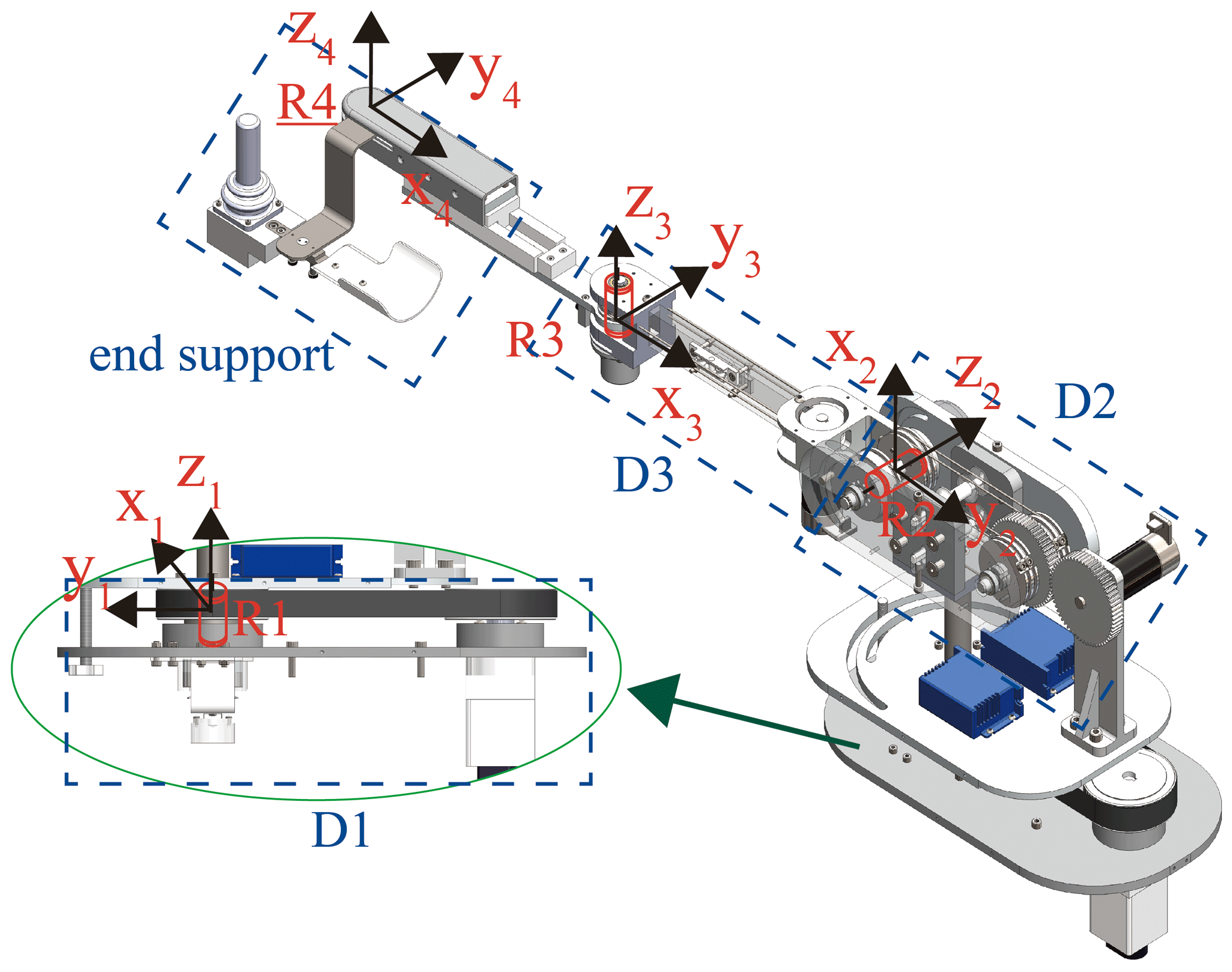
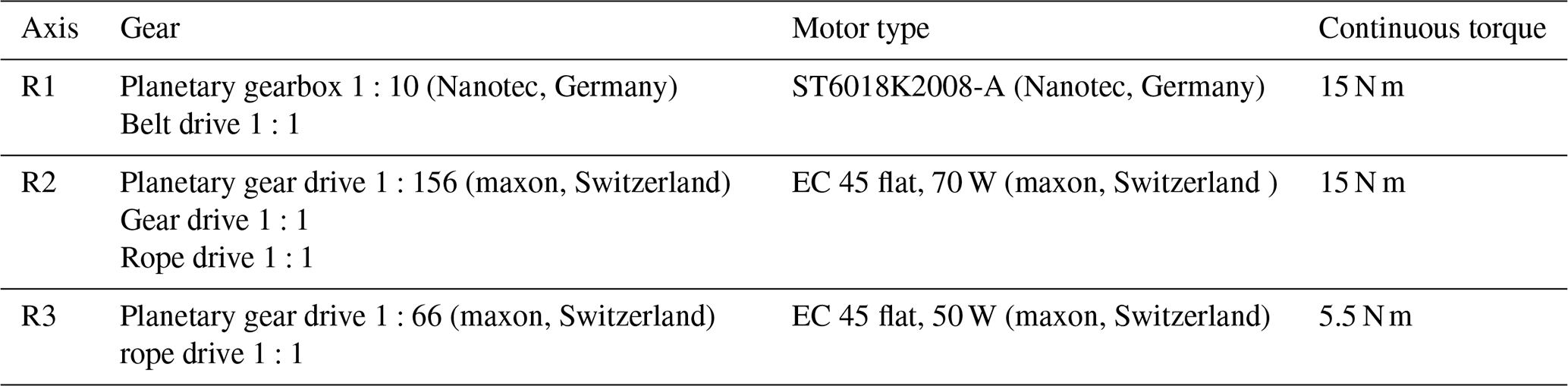
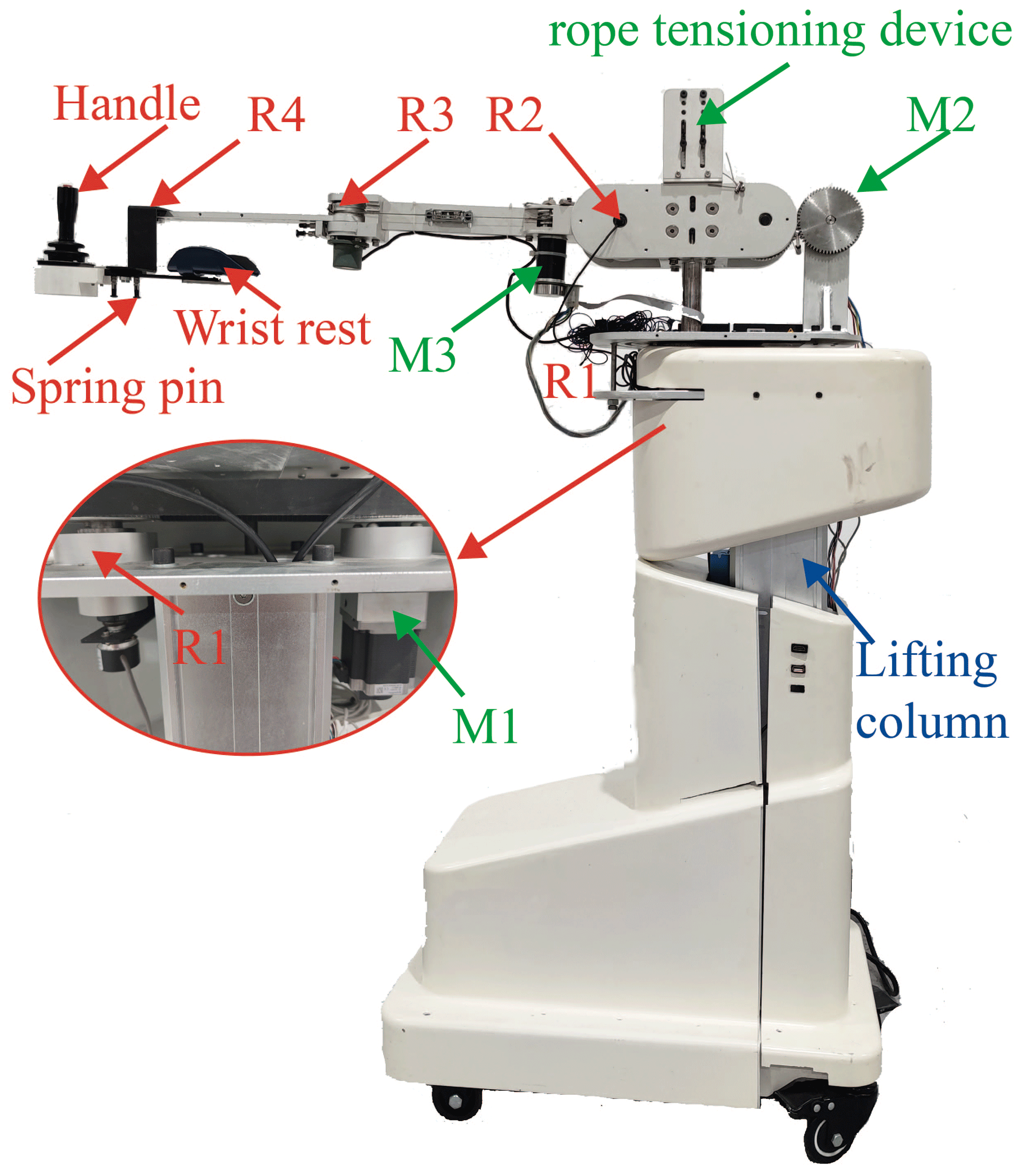
This paper proposes a 4 DOF end-effector-based upper limb rehabilitation robot according to the proposed configuration, as shown in Fig. 2. The drive systems D1, D2, and D3 of R1, R2, and R3 are shown in Table 1. The belt drive of D1 is used to reduce mechanical vibration. In order to ensure the stability of the structure, D2 is designed with a double rope drive. The D3 motor is set close to R2 to reduce the inertia of the robotic arm. The end support is composed of a Hall handle, wrist rest, and driven joint, R4. The patient can manipulate the Hall handle to control the robot for performing rehabilitation training for the upper limbs. The combination of R4 and the lockable joint on the front of the wrist rest can realize the interchangeability of left and right hands.
The physical human–robot interaction (pHRI) between the wearers and the exoskeleton robots is twofold, which necessitates the suitability of the exoskeleton structure for the wearers. Different aspects such as weight, actuation, power transmission, dexterity, singularity, workspace, kinematic chain, DOFs, and compliance are an important design reference under pHRI (Pons, 2008). Therefore, the robot configuration design based on multiple parameters is beneficial for improving the pHRI. To verify the kinematical performance of the configuration designed, the kinematical model of the designed configuration and the human upper limb are first established.
Table 2The coordinates of the spiral axes of the configuration.

3.1 Kinematic modeling of the configuration
In order to facilitate the subsequent kinematic performance analysis, the kinematic model of this configuration is established using the spinor method (Lynch and Park, 2017), as shown in Table 2 and Eqs. (2)–(4). The human shoulder joint coordinate system is used as the configuration's initial coordinate, and the human end coordinate system is the configuration end coordinate system since the end coordinate system of the human upper limb and the robot end coordinate system always coincide.
where Si is the spiral axis of the joint Ri, ωi and νi are the angular velocity and linear velocity of Si, respectively, (ωi, νi) is the coordinate of Si, M1 is the pose matrix of the robot end coordinate system O5-x5y5z5 when it is in the initial position, is the Rodriguez formula representing the matrix index of the spiral axis, Tr is the pose transformation matrix O4-x4y4z4 of the system relative to the fixed system Og-xgygzg, Rr is the 3 × 3 direction matrix of the coordinate system O5-x5y5z5, and Pr is the 3 × 1 position matrix of the coordinate systemO5-x5y5z5.
3.2 Kinematic modeling of the upper limb
To facilitate the study of upper limb kinematics, the International Society of Biomechanics (ISB) recommendations reduce the 3 DOFs of the shoulder joint to three sequential rotations around perpendicular axes, i.e., rotation of zg axis (plane of elevation), xg axis (angle of elevation), and zg axis (internal/external rotation; Wu et al., 2005). The elbow is relatively simple and can be modeled directly. Therefore, the kinematical model of the human upper limb is established by the spin method. The solution process of the pose transformation matrix Tb of the system Oh-x5y5z5 relative to the fixed system Og-xgygzg is as follows:

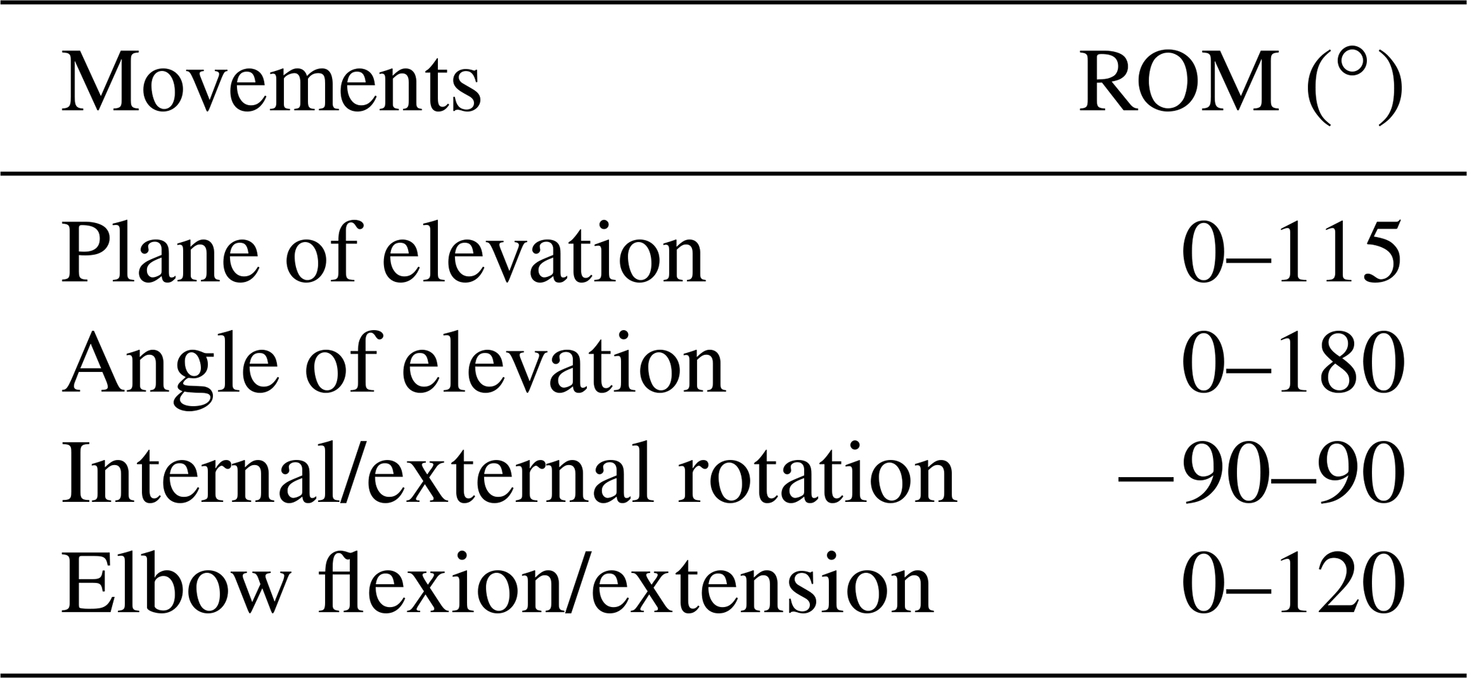
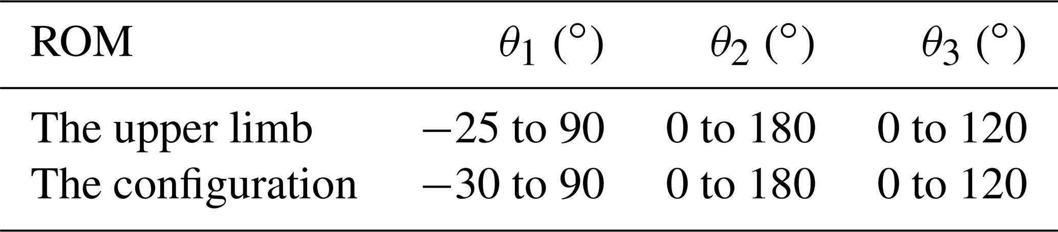
The ROM required for ADL by 95 % of the population is derived for the maximum values of the related work in (Namdari et al., 2012; Magermans et al., 2005; Gates et al., 2016) and translated to the ISB system, as shown in Table 4.
4.1 Workspace
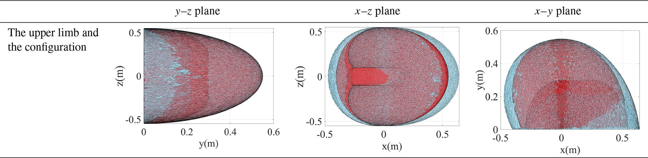
The workspace is the region described by the origin of the end-effector frame when all the manipulator joints perform all possible motions. Since the workspace of the rehabilitation robot should cover the workspace of the human upper limb as much as possible, the workspace of the human and the robot needs to be established and compared. First, to ensure the safety of the exoskeleton, the joints of the robot are restricted according to the ROM of the upper limb joints in the ISB system, as shown in Table 5. Second, the joint angle sets of the upper limb and the proposed configuration are established, respectively, by using the Monte Carlo method (Rubinstein and Kroese, 2017). Finally, the workspace of the upper limb and the proposed configuration are obtained by substituting the angle sets into kinematic equations, as shown in Table 6. Because human hands hardly reach the back of the body in rehabilitation, the points where x<0 are deleted. The red and blue regions display the workspace of the upper limb and the configuration, respectively.
In order to quantify the differences between the two workspaces, the workspace of the human upper limb is filtered by the boundary of the workspace of the configuration. The result is that the human workspace is composed of 392 870 points, of which the points in the workspace of the configuration are 379 535, accounting for 96.61 %, and the points that are not included are distributed in the marginal zone that is not often reached, so this configuration meets the design requirements in the workspace.
4.2 Global kinematical performance analysis
While the workspace of a robot arm is a total volume swiped out by the end effector when it executes all possible motions, the manipulability is the ability to arbitrarily the change the end-effector position and orientation (Kim and Khosla, 1991). The manipulability, which can be described by the velocity manipulability ellipsoid, is considered as a quantitative and performance measure of the type of rehabilitation robots. Because the postures of the end point of the human upper limb and the end point of the robot are always the same, the human–machine closed-chain mechanism (HMCCM) is established. The manipulability analysis of the HMCCM is performed.
4.2.1 Jacobian matrix of the HMCCM
Based on the posture matrix of the point where the end of the human upper limb and the end of the robot coincide, the kinematic constraint equations of the HMCCM can be expressed as follows:
where Pr(i,1) is the ith row and first column of the Pr matrix, and Rr() is the matrix that is composed of the first to third rows of the first column of the Rr matrix.
By differentiating θa, θf, θe, θ1, θ2, and θ3 in Eq. (8) to time t and simplifying the result, the Jacobian matrix of the HMCCM can be obtained, as shown in Eq. (9). Since R4 is a driven joint used to compensate for errors and is located at the end of the robotic arm, it has no effect on the flexibility of the robotic arm, so it is regarded as a known quantity.
where , , and are the angular accelerations of the shoulder adduction/abduction and flexion/extension and elbow flexion/extension, respectively, , , and are the angular accelerations of R1, R2, and R3, respectively. J is a matrix consisting of polynomials about θa, θf, θe, θ1, θ2, θ3, θ4, lb, lf, li ().
4.2.2 Manipulability
The manipulability measure (Cardou et al., 2010) is defined as follows:
The σi is the singular value of Jacobian matrix, the λi is the eigenvalue of the JJT, and m is the dimension of operation space, .
To normalize the manipulability, relative manipulability is specifically defined as follows:
where ηi is the manipulability of the coordinate point, ηmax is the maximum value of the configuration, the value range of μi is 0–1, and n is the number of the end points of the upper limb. In general, a higher μi shows better dexterous manipulation, while a lower value corresponds to limited manipulation.
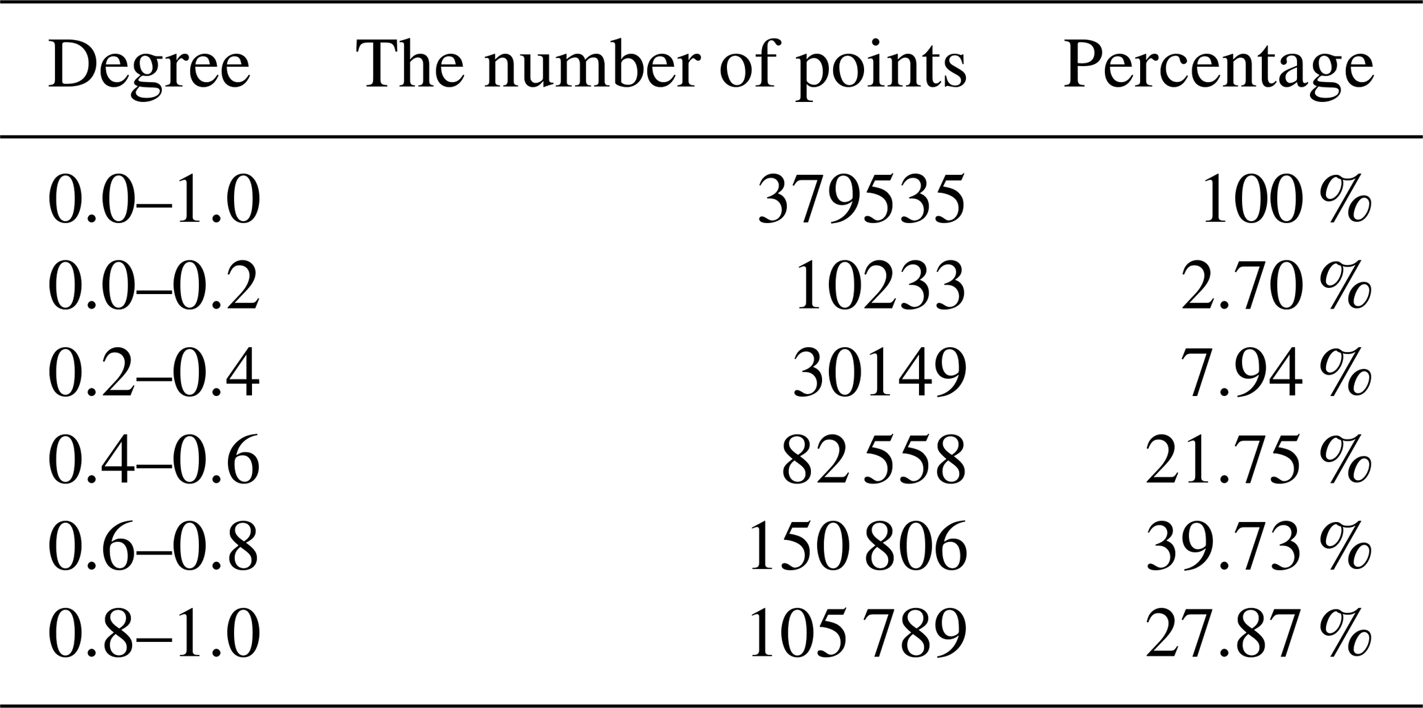
The value of μ is divided into five classes for the convenience of comparison. Since the points in the area where the robot workspace does not overlap with the upper limb workspace have no significance for analysis, the points of the upper limb workspace after filtrated by the workspace of the robot are used in Eqs. (10) and (11). The statistical results are shown in Table 7. During the movement, the angle of the robot joints is different from the angle of the upper limb joints. Therefore, based on the posture of the end point of the upper limb, the inverse kinematics solution of the robot at this position is solved by using the Newton–Raphson method to obtain the angle of each joint of the robot.
According to the actual situation, the region with relative manipulability above 0.6 is the region with better flexibility. So, the percentage of the relative manipulability above 0.6 of the HMCCM is 67.6 %, and the percentage of the relative manipulability below 0.4 is 10.64 %, which proves that the configuration has excellent kinematical performance in the overall workspace.
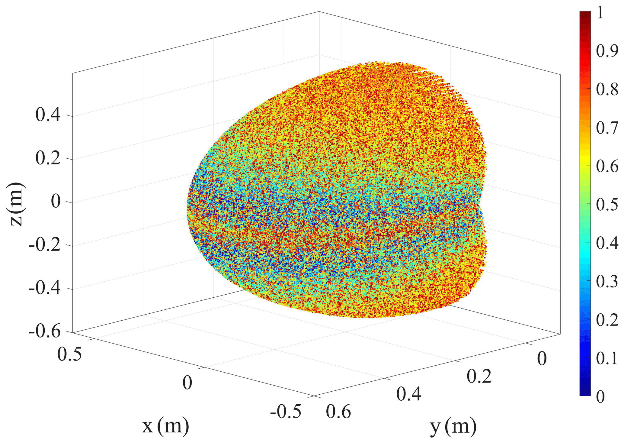
During upper limb rehabilitation training, the probability of the end of the exoskeleton reaching the edge of the workspace is less than the inside of the workspace. Therefore, the figures of relative manipulability combined with the workspace are plotted separately to compare the level of flexibility in the whole domain, as shown in Fig. 3. The closer the color is to red, the closer the value of μi is to 1, and the better the flexibility of this point.
It can be clearly seen from Fig. 3 that the low relative manipulability points of the configuration are concentrated in two narrow edges of the workspace. It has little effect on the overall flexibility of the configuration.
4.3 Local kinematical performance analysis
Drinking water training is often seen in rehabilitation exercises, where multiple joints can be trained simultaneously. In this paper, a trajectory of drinking water according to the kinematical model of human upper limbs is established and divided into 10 sample points. The inverse kinematical solutions of the configuration are obtained by the Newton–Raphson method (Ahmad et al., 2019), and the kinematical performance of the HMCCM on the trajectory is analyzed.
4.3.1 The joint angle
In the drinking water training, the initial posture of the upper limb is θa = 0∘, θf = 30∘, and θe = 0∘, and the end posture of the upper limb is θa = −10∘, θf = 80∘, and θe = 120∘. A joint trajectory is generated using MATLAB and divided into 10 sample points. The Cartesian coordinates of the sample points are obtained to solve the robot joint angles at these positions. The inverse kinematical solutions of the configuration are obtained by the Newton–Raphson method to obtain the angles of the active joints of the configuration at these sample points.
4.3.2 Manipulability ellipsoid
Since the manipulability index is proportional to the volume of the manipulability ellipsoid, it can be used to visualize the degree of manipulation in the operational space, that is (Rozo et al., 2017; Gunasekara et al., 2015). Therefore, the manipulability ellipsoids are constructed based on the Jacobian matrix and its singular values. In addition to the geometric characteristics of the manipulability ellipsoid, we define the following two parameters to measure the difficulty of the exoskeleton moving in a certain pose:
-
The ratio of the radius of the shortest axis to the longest axis of the manipulability ellipsoid can describe the kinematical performance of the exoskeleton in all directions. When the ratio is closer to 1, the manipulability ellipsoid is close to spherical, which means that the exoskeleton is equally easy to move in any direction. Thus, we have the following:
-
The volume of the manipulability ellipsoid can directly describe the kinematical performance of the exoskeleton in a certain pose. The larger the volume, the better the sports performance. Thus, we have the following:

The ellipsoids corresponding to the HMCCM in each step of the trajectory are obtained by MATLAB, as shown in Fig. 4. The red curve is the trajectory of the end of the human upper limb. The manipulability ellipsoids of the HMCCM are drawn on the corresponding sample joints. The size of the ellipsoids is reduced by 25 times for the convenience of expression. The results show that the manipulability ellipsoids of the robot are close to the spherical shape in the first 70 % of the trajectory, and the isotropy of the subsequent trajectory is significantly reduced, but the K value is still greater than 0.5, while the volume of the ellipsoids are gradually increasing. Therefore, it is proved that the robot is far away from the singularity on the drinking trajectory and has good kinematical performance.
5.1 Mechanical design
The prototype of the end-effector-based upper limb rehabilitation robot is designed in detail according to the verified configuration. The robot prototype is composed of a base seat, a drive system, and a robotic arm, as shown in Fig. 5. The drive system and the robotic arm are installed on an actuated lifting column of the base seat to adjust for different heights. The drive system includes three drive motors and the rope drive to provide power for the robotic arm. The rope tensioning device is designed to prevent the deformation of the wire rope from affecting the transformation efficiency. The robotic arm includes three active joints, a driven joint, and an end support module. R4 and the spring pin cooperate to realize the reversal of left and right hands.
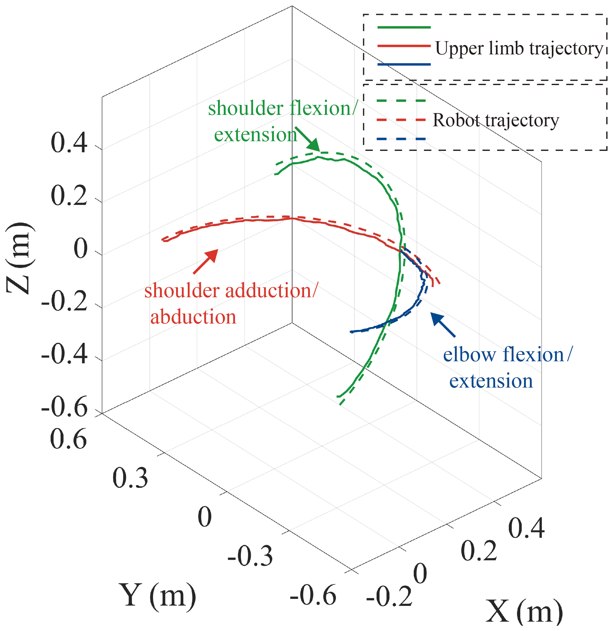
Figure 6The upper limb trajectories and the robot trajectories in the smooth pursuit movement tests.
5.2 Smooth pursuit movement test
This paper performs a series of smooth pursuit movement experiments with a healthy male subject, who is 26 years old, to evaluate the ability of the proposed mechanism. Smooth pursuit movement is the movement of the tester's arm driven by the robot (Meng et al., 2019). These test motions include the shoulder flexion/extension and adduction/abduction and the elbow flexion/extension. The motion analysis system is utilized to test the motion angles of the human arm in real time. A total of three pose sensors are set at R1, R2, and R3 to test the motion angles of the proposed mobile robotic arm, and the angles are smoothed using MATLAB's smoothing function to reduce the angle error caused by mechanical vibration. The two groups of angles of motion for each group experiment are obtained, and these are substituted into the kinematical models of the upper limb and the robot to obtain their motion trajectories, as shown in Fig. 6. The green, red, and blue solid lines represent the trajectories of the end of the human upper limb in the shoulder flexion/extension and adduction/abduction and the elbow flexion/extension, and the green, red, and blue dotted lines represent the end trajectory of the robot in the corresponding motions.
The root mean square error (RMSE) and Pearson correlation coefficient (PCC) are used to analyze the motion error between the human arm and the robot, as shown in Eqs. (9) and (10).
where δ is the RMSE, γx, γy, and γz are the coordinate values of the end trajectory points of the robot, βx, βy, and βz are the coordinate values of the end trajectory points of the human upper limb, and N is data bulk.
where P is the RMSE, γ is the coordinate matrix of the trajectory points of the robot, β is the coordinate matrix of the trajectory points of the human upper limb, Cov(γ,β) is the covariance of γ and β, Var[γ] is the variance of γ, and Var[β] is the variance of β. The errors are obtained by substituting the data of three smooth pursuit movement experiments into Eqs. (9) and (10). The results are as follows: the shoulder flexion/extension – δ=0.019, P=0.9997; the shoulder adduction/abduction – δ=0.016, P=0.9998; and the elbow flexion/extension– δ=0.016, P=0.9998. The results show that the motion trajectory of the robot basically coincides with the motion trajectory of the human upper limb. Due to inevitable factors such as the calibration error of the motion analysis system, a certain error between the trajectories is acceptable. Based on the above results, it can be concluded that the upper limb rehabilitation robot can assist the human upper limb for single-joint training.
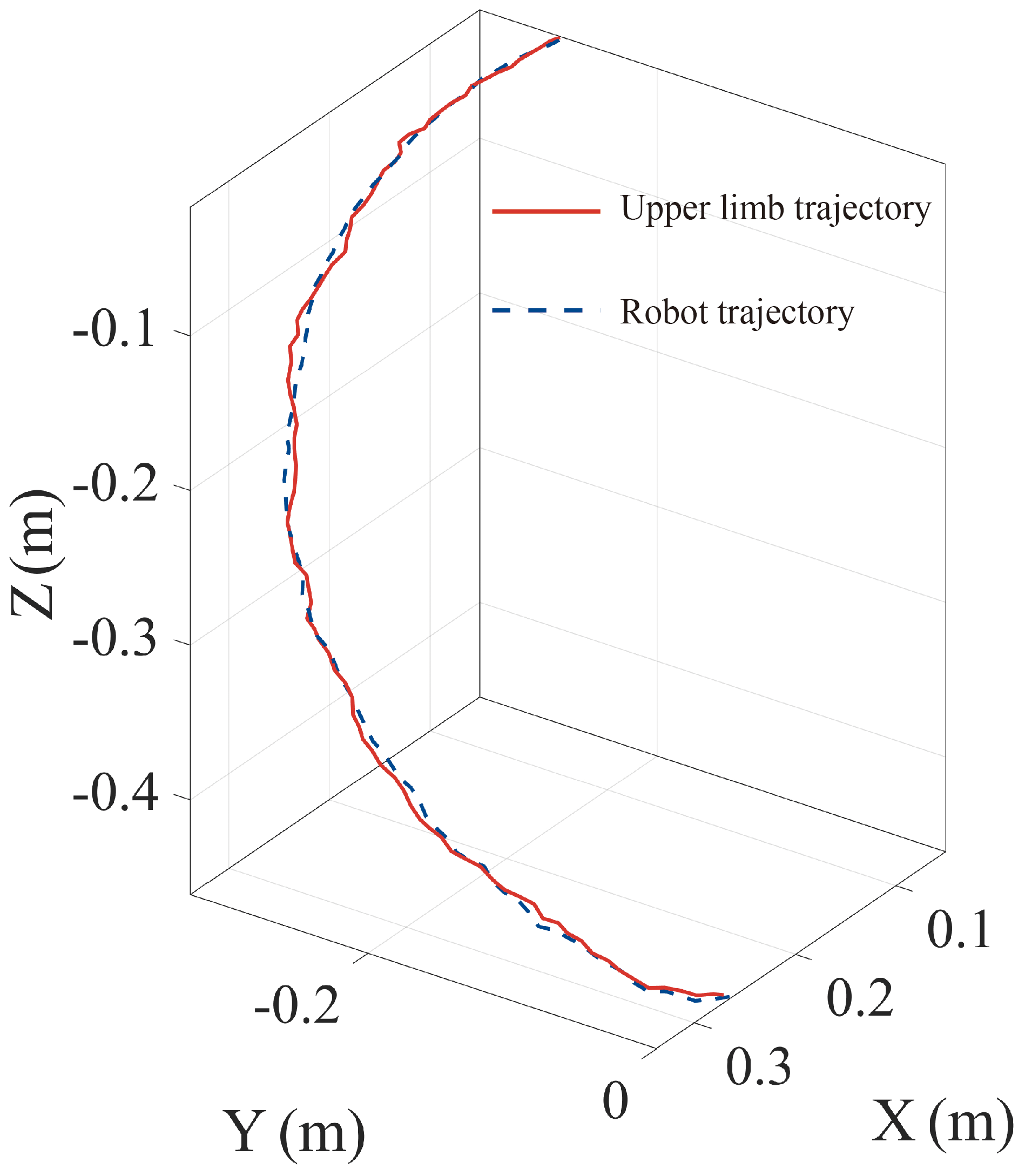
Figure 7The upper limb trajectory and the robot trajectory in the multi-joint exercise test.
5.3 The multi-joint exercise test
The drinking posture training experiment is designed to verify the multi-DOF motion control ability of the robot. The human upper limb is trained to drink with the assistance of the rehabilitation robot, and the joint angle changes of the upper limb joints and the active joints of the robot are recorded, respectively. The motion trajectories of the upper limb and the robot are obtained by substituting the obtained joint angles into the corresponding kinematic models, as shown in Fig. 7. The RMSE of the two trajectories is 0.0067, and the PCC is 0.9989, which indicates the coincidence of the two trajectories. The results show that the upper limb rehabilitation can assist the upper limbs in performing rehabilitation training with multiple DOFs well.
This paper proposes a novel 4 DOF end-effector-based upper limb rehabilitation robot with space training. Based on the kinematical models of the mechanism, the human upper limb, and the HMCCM, several kinematical performance parameters of the proposed mechanism are analyzed. The results show that the overlap of the workspace between the mechanism and the human upper limb is 96.61 %, the highly flexible area of the mechanism accounts for 67.6 %, and the mechanism is far away from the singularity on the drinking trajectory. These results indicate that the proposed mechanism has excellent movement to satisfy the requirements of human upper limb rehabilitation. Finally, a prototype of the proposed mechanism is designed, and the smooth pursuit movement test and the multi-joint exercise test are performed to verify the effectiveness of the robot and its ability to perform active training. The results prove that the robot can satisfy the flexibility and safety requirement of the patients during upper limb rehabilitation training.
All data included in this study are available upon request from the corresponding author.
QM proposed and developed the overall concept of the paper and conducted the mechanism design and analysis. ZJ edited the paper and helped write the paper. HY supervised and structured the paper. WZ helped to make the figures.
The authors declare that they have no conflict of interest.
The authors would like to thank the National Natural Science Foundation of China (grant no. 61803265) and the Shanghai Municipal Commission of Science and Technology (grant no. 20S31905400) for their support.
This research has been supported by the Foundation for Innovative Research Groups of the National Natural Science Foundation of China (grant no. 61803265) and the Science and Technology Commission of Shanghai Municipality (grant no. 20S31905400).
This paper was edited by Guowu Wei and reviewed by Qitao Huang and one anonymous referee.
Ahmad, M., Kumar, N., and Kumari, R.: A hybrid genetic algorithm approach to solve inverse kinematics of a mechanical manipulator, International Journal of Scientific & Technology Research, 8, 1772–1782, 2019.
Béjot, Y., Daubail, B., and Giroud, M.: Epidemiology of stroke and transient ischemic attacks: Current knowledge and perspectives, Rev. Neurologia (Paris), 172, 59–68, 2016.
Bertani, R., Melegari, C., De Cola, M. C., Bramanti, A., Bramanti, P., and Calabrò, R. S.: Effects of robot-assisted upper limb rehabilitation in stroke patients: a systematic review with meta-analysis, Neurol. Sci., 38, 1561–1569, https://doi.org/10.1007/s10072-017-2995-5, 2017.
Cardou, P., Bouchard, S., and Gosselin, C.: Kinematic-sensitivity indices for dimensionally nonhomogeneous jacobian matrices, IEEE T. Robot., 26, 166–173, https://doi.org/10.1109/TRO.2009.2037252, 2010.
Chang, C. K., Washabaugh, E. P., Gwozdziowski, A., Remy, C. D., and Krishnan, C.: A Semi-passive Planar Manipulandum for Upper-Extremity Rehabilitation, Ann. Biomed. Eng., 46, 1047–1065, https://doi.org/10.1007/s10439-018-2020-z, 2018.
Gates, D. H., Walters, L. S., Cowley, J., Wilken, J. M., and Resnik, L.: Range of motion requirements for upper-limb activities of daily living, Am. J. Occup. Ther., 70, 1–10, https://doi.org/10.5014/ajot.2016.015487, 2016.
Gunasekara, M., Gopura, R., and Jayawardena, S.: 6-REXOS: Upper limb exoskeleton robot with improved pHRI, Int. J. Adv. Robot. Syst., 12, 1–13, https://doi.org/10.5772/60440, 2015.
Hogan, N., Krebs, H. I., Charnnarong, J., Srikrishna, P., and Sharon, A.: MIT-MANUS: a workstation for manual therapy and training. I, in: IEEE International Workshop on Robot and Human Communication, Tokyo, Japan, 1–3 September 1992, 161–165, 1992.
Jarrase, N., Maestrutti, M., Morel, G., and Roby-Brami, A.: Robotic prosthetics: beyond the technical performance: A study of socio-anthropological and cultural phenomena influencing the appropriation of technical objects interacting with the body, IEEE Technol. Soc. Mag., 34, 71–79, 2015.
Kikuchi, T., Nagata, T., Sato, C., Abe, I., Inoue, A., Kugimiya, S., Ohno, T., and Hatabe, S.: Sensibility Assessment for User Interface and Training Program of An Upper-Limb Rehabilitation Robot, D-SEMUL, Proc. Annu. Int. Conf. IEEE Eng. Med. Biol. Soc. EMBS, Honolulu, Hawaii, 17–21 July 2018, 3028–3031, https://doi.org/10.1109/EMBC.2018.8513074, 2018.
Kim, B. and Deshpande, A. D.: An upper-body rehabilitation exoskeleton Harmony with an anatomical shoulder mechanism: Design, modeling, control, and performance evaluation, Int. J. Robot. Res., 36, 414–435, https://doi.org/10.1177/0278364917706743, 2017.
Kim, J. O. and Khosla, P.: Dexterity measures for design and control of manipulators, in: IEEE/RSJ International Workshop on Intelligent Robots and Systems '91, Osaka, Japan, 3–5 November 1991, 758–763, 1991.
Loureiro, R., Amirabdollahian, F., Topping, M., Driessen, B., and Harwin, W.: Upper Limb Robot Mediated Stroke Therapy–GENTLE/s Approach, Autonomous Robots., 15, 35–51, https://doi.org/10.1023/A:1024436732030, 2003.
Lum, P. S., Burgar, C. G., Shor, P. C., Majmundar, M., and Van der Loos, M.: Robot-assisted movement training compared with conventional therapy techniques for the rehabilitation of upper-limb motor function after stroke, Arch. Phys. Med. Rehab., 83, 952–959, https://doi.org/10.1053/apmr.2001.33101, 2002.
Luo, L., Peng, L., Wang, C., and Hou, Z. G.: A Greedy Assist-as-Needed Controller for Upper Limb Rehabilitation, IEEE T. Neur. Net. Lear., 30, 3433–3443, https://doi.org/10.1109/TNNLS.2019.2892157, 2019.
Lynch, K. M. and Park, F. C.: Modern Robotics: Mechanics, Planning, and Control, Cambridge Univeristy Press, 2017.
Magermans, D. J., Chadwick, E. K. J., Veeger, H. E. J., and Van Der Helm, F. C. T.: Requirements for upper extremity motions during activities of daily living, Clin. Biomech., 20, 591–599, https://doi.org/10.1016/j.clinbiomech.2005.02.006, 2005.
Manna, S. K. and Dubey, V. N.: A mechanism for elbow exoskeleton for customised training, in: 2017 International Conference on Rehabilitation Robotics (ICORR), London, UK, 17–20 July 2017, 1597–1602, 2017.
Meng, Q., Xie, Q., Shao, H., Cao, W., Wang, F., Wang, L., Yu, H., and Li, S.: Pilot Study of a Powered Exoskeleton for Upper Limb Rehabilitation Based on the Wheelchair, Biomed Res. Int., 2019, 1–11, https://doi.org/10.1155/2019/9627438, 2019.
Namdari, S., Yagnik, G., Ebaugh, D. D., Nagda, S., Ramsey, M. L., Williams, G. R., and Mehta, S.: Defining functional shoulder range of motion for activities of daily living, J. Shoulder Elb. Surg., 21, 1177–1183, https://doi.org/10.1016/j.jse.2011.07.032, 2012.
Nef, T., Guidali, M., and Riener, R.: ARMin III – arm therapy exoskeleton with an ergonomic shoulder actuation, Appl. Bionics Biomech., 6, 127–142, https://doi.org/10.1080/11762320902840179, 2009.
Otten, A., Voort, C., Stienen, A., Aarts, R., Van Asseldonk, E., and Van Der Kooij, H.: LIMPACT: A Hydraulically Powered Self-Aligning Upper Limb Exoskeleton, IEEE/ASME Transactions on Mechatronics, 20, 2285–2298, https://doi.org/10.1109/TMECH.2014.2375272, 2015.
Perry, J. C., Rosen, J., and Burns, S.: Upper-Limb Powered Exoskeleton Design, IEEE/ASME Transactions on Mechatronics, 12, 408–417, 2007.
Pons, J. L.: Wearable Robots: biomechatronic Exoskeletons, John Wiley & Sons, Inc., New Jersey, USA, 2008.
Rozo, L., Jaquier, N., Calinon, S., and Caldwell, D. G.: Learning manipulability ellipsoids for task compatibility in robot manipulation, 2017 IEEE/RSJ International Conference on Intelligent Robots and Systems (IROS), Vancouver, Canada, 24–28, September 2017, 3183–3189, 2017.
Rubinstein, R. Y. and Kroese, D. P.: Simulation and the Monte Carlo Method, John Wiley & Sons, Inc., New Jersey, USA, 2017.
Wu, G., Van Der Helm, F. C. T., Veeger, H. E. J., Makhsous, M., Van Roy, P., Anglin, C., Nagels, J., Karduna, A. R., McQuade, K., Wang, X., Werner, F. W., and Buchholz, B.: ISB recommendation on definitions of joint coordinate systems of various joints for the reporting of human joint motion – Part II: Shoulder, elbow, wrist and hand, J. Biomech., 38, 981–992, https://doi.org/10.1016/j.jbiomech.2004.05.042, 2005.
Zhang, L., Li, J., Su, P., Song, Y., Dong, M., and Cao, Q.: Improvement of human–machine compatibility of upper-limb rehabilitation exoskeleton using passive joints, Robot. Auton. Syst., 112, 22–31, https://doi.org/10.1016/j.robot.2018.10.012, 2019.