the Creative Commons Attribution 4.0 License.
the Creative Commons Attribution 4.0 License.
 | 04 Jun 2021
Scheme optimization for a turbine blade under multiple working conditions based on the entropy weight vague set
Guodong Yi
Huifang Zhou
Yang Wang
Jingli Wu
Jundi Wu
The deformation of blades under complex loads of multiple working conditions will reduce the energy conversion efficiency. To reduce the deviation of the blade shape in practical working conditions, a combination and optimization method of blade design schemes under multiple working conditions, based on the entropy weight vague sets, is proposed. The sensitivity of each working condition index is analyzed based on the information entropy, and the satisfaction degree of the design scheme based on the design requirements and experiences is described with the vague set. The matching degree of different design schemes for multiple working conditions is quantified according to the scoring function. The combination and optimization of the design scheme are verified by numerical simulation analysis. The results show that the proposed design scheme has a smaller blade shape deviation than the traditional design scheme under multiple working conditions.
- Article
(997 KB) - Full-text XML
- BibTeX
- EndNote


As a power source for driving large equipment by converting the heat and kinetic energy of steam into mechanical energy, steam turbines are very important equipment in industrial production, with good thermal economy, adaptability and compatibility (Sarkar, 2015).
As typical high-energy-consumption equipment, steam turbines are very sensitive to the requirements of energy efficiency. Steam turbines that run under design conditions have the highest efficiency. However, the operation of steam turbines often deviates from the design conditions due to the effect of various factors, such as steam conditions and load conditions, which reduce the power performance and economic performance (Ahmad et al., 2019; Bhagi et al., 2018).
The high-temperature and high-pressure steam enters the cylinder of a steam turbine, acts on the surface of the blades and drives the spindle to rotate to realize the energy conversion and output. Therefore, the blades are very important for the energy conversion efficiency of a steam turbine (Chatterjee, 2016; Choi et al., 1999).
In traditional methods, the blade is typically designed based on the analysis of the aerodynamic performance of a steam turbine under single and ideal working conditions to obtain the ideal shape, and the reliability is determined by analyzing the strength, modality and life (Dulau and Bica, 2014; Kim et al., 2013; Eleftheriou et al., 2017; Kaneko et al., 2017; Lucacci, 2017; Prabhunandan and Byregowda, 2018; Shukla and Harsha, 2015; Tanuma, 2017). However, during the operation, multiple complex loads cause the actual shape of the blade to deviate from the ideal blade shape obtained by the theoretical design (Zhu et al., 2017). The deviation of the blade shape will affect the aerodynamic performance and reduce the efficiency of the turbine. Therefore, the ideal blade shape cannot be directly used for manufacturing (Diamond et al., 2019). The ideal blade shape must satisfy the aerodynamic performance requirements of the steam turbine under the designed working conditions.
The pre-deformation design method has been proposed to reduce the deviation between the hot blade shape and ideal blade shape (Chen and Lin, 2000; Kamoun et al., 2006; Hou et al., 2016; Albanesi et al., 2017; Chen et al., 2017; Albanesi et al., 2018; Kollar and Mishra, 2019; Saeed et al., 2019). The blade shape determined by manufacturing is the cold blade shape. Under the designed working conditions, the blade will deform under the action of multiple complex loads, and the stable shape of the blade is the hot blade shape. The main process of the pre-deformation design method is as follows: first, the ideal blade shape is designed by the theoretical calculation method; second, a hot shape is constructed according to the loads that act on the blade by taking the ideal blade shape as the cold blade shape; third, the geometric deviation between the hot blade shape and the ideal blade shape is calculated; finally, the deviation is reversely applied to the ideal shape to obtain a new cold shape that satisfies the design expectations.
The deformation of a blade is very complicated due to its variable cross section and torsional shape, the complex and nonlinear steam flow field around it and their coupling effect (Choi et al., 1999; Chaibakhsh and Ghaffari, 2008; Wood and Morton, 1984; Fadl et al., 2018). Therefore, it is difficult to obtain accurate deformation of a blade using calculations and analyses based on theoretical formulas (Moheban and Young, 1985).
With the development of the finite element method and computational fluid dynamics technology (Bhagi et al., 2018; Prabhunandan and Byregowda, 2018; Shukla and Harsha, 2015; Brahimi and Ouibrahim, 2016; Hashemian et al., 2020; Jang et al., 2015; Francesco et al., 2017), iterative solutions of the pre-deformation design method based on numerical calculations have gradually been used in blade analysis and optimal design (Noori Rahim Abadi et al., 2017; Obert and Cinnella, 2017; Pascoa et al., 2009; Hou et al., 2019; Li et al., 2019; Jiang et al., 2019; Yi et al., 2020a, b). With these methods, the construction of a hot shape and the correction of a cold shape are alternately and repeatedly executed in the pre-deformation design process.
The steam turbines must change the main operating parameters with the load changes of the driven machinery. Therefore, the state of the steam flow and the power and rotating speed of the steam turbine fluctuate in a certain range during the operation. The operating state of steam turbines is affected by various factors, such as steam conditions and load conditions, so the operating state deviates from the designed working conditions. Different operating conditions will directly affect the working status of the low-pressure stage blades and then the deviation between hot blade shape and ideal blade shape. Therefore, it is necessary to consider the effect of multiple operating conditions in the blade design.
The aforementioned blades designed for a single, specific working condition have difficulty adapting to the requirements of multiple working conditions. To solve this problem, this paper studies a correlation analysis method between the blade design and multiple working conditions. A combination optimization strategy under multiple working conditions is obtained by synthesizing the analysis results of multiple design schemes, and the blade shape design is guided to adapt to the multiple working conditions of steam turbines.
During the operation, the steam turbine generally runs under multiple operating conditions. The change in working conditions will affect the flow state of the fluid in the cylinder and the external load on the blades. According to the analysis of working conditions, based on available data and design experiences, factors such as the steam flow, spindle speed, adaptability to load fluctuations, power, exhaust pressure, working loss of the condensing equipment and running stability describe the main differences in the multiple working conditions of a steam turbine, and they can be used as the main indices to characterize the working conditions. Therefore, different working conditions can be represented as vectors of the main indices.
The steam turbines must change the main operating parameters with the load changes of the driven machinery. Therefore, the state of the steam flow and the power and rotating speed of the steam turbine will fluctuate in a certain range under multiple working conditions. Because there may be uncertainty in determining the effect of these main indices on the working conditions of the steam turbine at the design stage, the informational entropy (Shannon entropy; Shannon, 1948) is used to describe the uncertainty of these indices; i.e., the entropy in each index is used to describe its value range.
If an index has N values during the evolution of the working conditions, and the probability of each value is , the entropy to describe the index is defined as follows:
where and .
In the design of blades under multiple working conditions, it is assumed that there are m working condition indices and n blade design schemes. The decision matrix is constructed according to the relationship between the working condition indices and the blade design schemes as follows:
where fij is the value of the working condition index that corresponds to design scheme . Each entry in a decision matrix is the preset value given by the operator according to the working conditions of the steam turbine.
Decision matrix F must be standardized due to the nonuniformity of the dimensions caused by the diversity of indices. Different types of indices are standardized using different methods (Kickert, 1978; Chen and Tan, 1994).
The value of the benefit index is expected to be maximal; thus, in the following, let
The value of the cost index is expected to be minimal; thus, in the following, let
The value of the quantitative index is expected to be closer to a fixed value ; thus, in the following, let
The qualitative evaluation indices of the natural language are divided into 10 grades, which are represented by numbers 1–10 and from low to high.
The results calculated by the aforementioned equations are the membership degree of the indices, which are substituted into decision matrix F in Eq. (2) to obtain the membership degree matrix . The certainty and normalization of the membership degree of the index is suitable for determining the entropy value of the index using a probability-based method.
The entropy value of the ith index is defined as follows:
where, in the following:
The meaning of entropy in information theory shows that uncertainty will increase when the distribution of information tends to be consistent. Equation (6) shows that when μij is closer to μi, the calculated entropy increases.
In the entropy weight method, the entropy value is normalized after being compensated according to the change in index value and used as the sensitivity of the index. The sensitivity of index i is as follows:
Let and normalize 1−ei to obtain the sensitivity ωi of index i as follows:
The sensitivity vector of the index calculated according to Eq. (9) is .
The vague set includes both membership and non-subordination information. It extends the membership degree assigned to each object from a number to a subinterval of [0, 1]. This subinterval provides evidence for x∈X and evidence against x∈X (Gau and Buehrer, 1993). If there is a universe , and are elements of universe U, a vague set A of universe U is described by a positive membership degree function tA and a negative membership degree function fA.
where tA(ui) is the lower bound of the positive membership degree derived from the evidence supporting ui, fA(ui) is the lower bound of the negative membership degree derived from the evidence against ui, and ; thus, the membership degree of ui is a subinterval of the interval [0,1].
In the analysis of design schemes under multiple working conditions, the lower bounds of the positive membership degree and negative membership degree show the suitability and unsuitability of the design scheme for multiple working conditions, respectively. Both tA(ui) and fA(ui) are the results obtained after introducing subjective empirical factors; thus, tA(ui) and 1−fA(ui) can be considered the lower and upper bounds of the designer's satisfaction degree with a design scheme, respectively. Therefore, the variation range of the designer's satisfaction degree, regarding the design scheme under multiple working conditions, can be expressed by the membership degree interval of the design scheme relative to the vague set of the design scheme.
Since domain U of multiple working conditions is discrete, vague set A of the satisfaction degree of the design scheme can be expressed as follows:
All membership degrees of the working condition indices after normalization are real numbers in the interval [0,1]. The lower bound of satisfaction degree λA and the upper bound of dissatisfaction degree λB of each working condition index accepted by the designer can be set based on the vague set.
If μij is greater than λA, scheme j is satisfied with index i. In the following set,
is the supporting index set of scheme j, and each index in the set is satisfied with scheme j.
If μij is less than λB, scheme j is not satisfied with index i. In the following set,
is the opposing index set of scheme j, and each index in the set is against scheme j.
If μij is less than λA but larger than λB, scheme j is between satisfaction and dissatisfaction for index i. In the following set,
is the neutral index set of scheme j, and each index in the set is neutral to scheme j.
The lower bound of satisfaction degree λA and the upper bound of dissatisfaction degree λB are separately determined for each index by referring to the experience of k experts to avoid the effect of the subjective arbitrariness of the designer on the bounds.
The bounds given by expert for index are (, ), where and are the lower bound of the satisfaction degree and the upper bound of the dissatisfaction degree of index i accepted by expert q, respectively. The lower bounds of the satisfaction degree and the upper bounds of the dissatisfaction degree, given by k experts on m indices, form the following matrix:
The lower bound of the satisfaction degree and the upper bound of the dissatisfaction degree of each index based on matrix K are determined as follows:
The aforementioned calculation of and fully considers the opinions of experts and avoids the subjectivity of the designers.
The sensitivity vector and the index membership degree matrix of each scheme obtained by the entropy weight method can be expressed by the vague estimated value vj for any scheme xj∈X that satisfies the decision requirements on m indices as follows:
where, in the following:
Therefore, each scheme corresponds to a vague value, which is used to measure the suitability of the scheme to the design requirements.
For vague value , the evaluation function is as follows:
and is used to calculate the matching degree of scheme j to the design requirements. The value of S1(xj) is first calculated, and a larger value corresponds to a higher matching degree of scheme j to the design requirements. If S1(xj) is identical, the value of S2(xj) is calculated, and a larger value corresponds to a higher degree of matching scheme j to the design requirements.
The results of the evaluation function are normalized to obtain the combined strategy factors of the design scheme of the blade shape as follows:
The design scheme is combined and optimized, based on Eq. (22), to obtain the final blade shape as follows:
A set of blades is known as a stage, and there are many stages in a steam turbine. A rotor blade in the low-pressure stage of a steam turbine is used as an example.

Figure 1Analysis models and meshes of the blades. (a) Blade model and the (b) mesh of the blade with the flow field model.
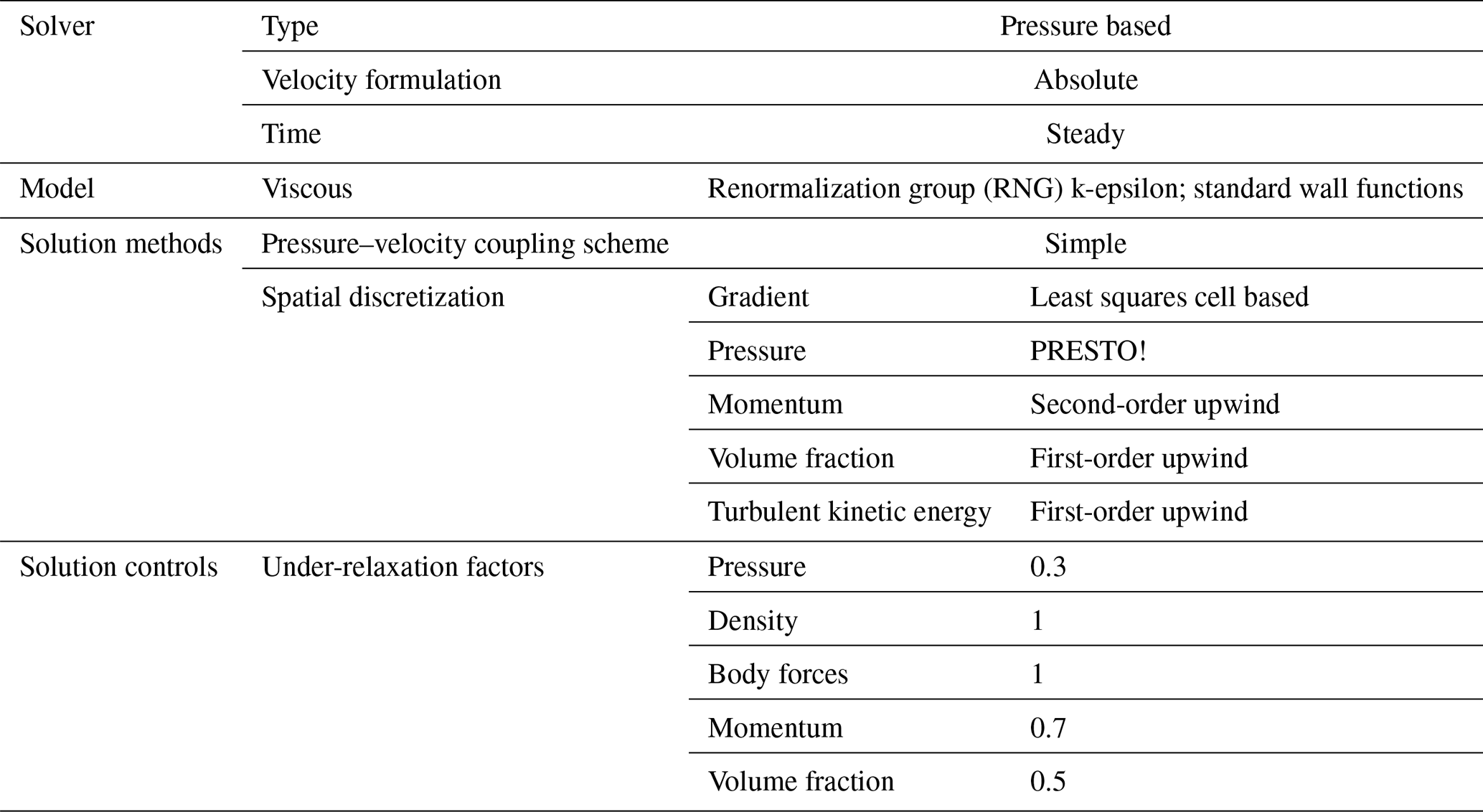
Table 1Settings of the computational fluid dynamics (CFDs) analysis.
5.1 Strategy factors of the combination design
A total of five different design schemes under different design working conditions are conducted to combine and optimize the design of the blade shape. The flow rate, rotation speed, load fluctuation control ability, power, exhaust pressure, operation loss of condensing equipment and operation stability are selected as the indices of the working conditions of the steam turbine. These indices of the working conditions can be obtained and calculated by the numerical simulation, and detailed information about the numerical simulation is described in Sect. 5.2.
The load fluctuation control capability is a benefit index, the operation loss of the condensing equipment and operation stability of the unit are the cost indices and the remainder is the quantitative indices. According to Eqs. (2)–(5), a decision matrix is instantiated as follows:
and the membership degree matrix is as follows:
The entropy values of the indices, calculated according to Eq. (6), are as follows:
The sensitivities of the indices after normalization are as follows:
The lower bound of the satisfaction degree and the upper bound of the dissatisfaction degree are provided for each index based on the design experience of five experts. The following matrix is obtained according to Eq. (14):
The lower bound of the satisfaction degree and the upper bound of the dissatisfaction degree for each index obtained, according to Eqs. (15) and (16), are as follows:
The vague estimated values of the five design schemes are calculated according to the support index set, opposition index set and neutral index set of each scheme as follows:
The matching degree of each design scheme is obtained, according to Eq. (21), as follows:
The combination strategy factor of the design scheme of the blade shape is obtained, according to Eq. (22), as follows:
This set of design combination strategy factors is used for the combination of design schemes of the blade shape.
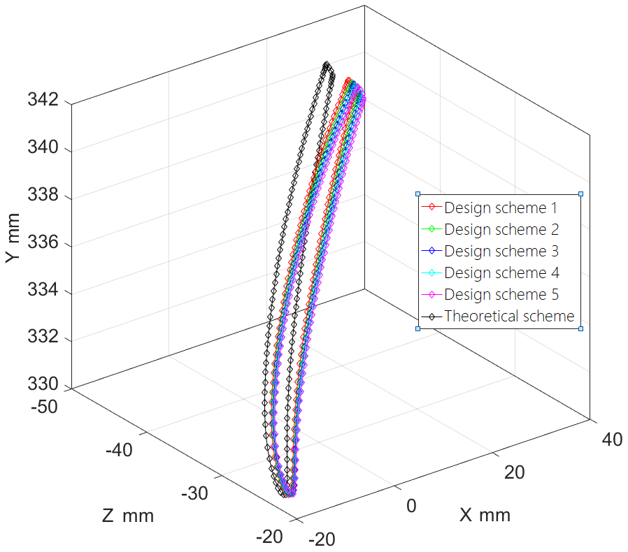


Figure 4Comparison of the spatial position of the nodes at the trailing edge of the blade tip.
5.2 Deviation of the blade shape
To verify the effectiveness of the proposed method, the combination design scheme under multiple working conditions is compared to the design scheme under single working conditions by calculating the deviation of the hot blade shape from the ideal blade shape.
The entire blade is analyzed based on an Ansys CFD numerical simulation. A 3D analysis model that includes only the working part of the blade is established, as shown in Fig. 1a. The model rotates around the z axis, and the y and x axes correspond to the radial and tangential directions, respectively. Unstructured tetrahedral meshes are used to mesh the flow field on the complex surface of the rotor blade. The meshes of the flow field model and blade model are shown in Fig. 1b.
The CFD analysis conditions are as follows: the inlet pressure is 49.25 kPa, the temperature is 348.27 K, and the outlet pressure is 0.0135 MPa. The settings for the CFD analysis are shown in Table 1.
The design of steam turbine blades under different working conditions results in five different blade shapes. The spatial positions of the nodes at the contour line and trailing edge of the blade tip are shown in Figs. 2 and 3, respectively.
The five blade design schemes are combined according to the aforementioned blade design combination strategy factors, and the final design optimization result under multiple working conditions is obtained. The relationship between the design results is most evident in the trailing edge of the blade tip. The spatial position of the nodes at the trailing edge of the blade tip is compared for the combination of the design schemes under multiple working conditions and the single-design scheme under the ideal working conditions, as shown in Fig. 4.
The operation analysis of the two blade design schemes is performed under each working condition, and their weighted cumulative deviations are compared according to the importance of each working condition.
The calculation method for the weighted cumulative deviation D of multiple operating conditions is as follows:
where i is the node number, m is the total number of grid nodes, j is the working condition number that corresponds to the design scheme, and n is the total number of working conditions.
The maximum deviations between hot blade shape and theoretical blade shape, obtained by the Ansys CFD numerical analysis of the two schemes under the aforementioned working conditions, are shown in Table 2.
Table 2Maximum deviations of the two schemes under the aforementioned working conditions.
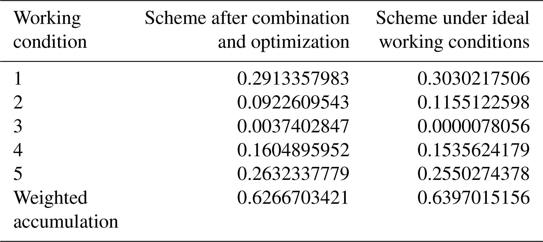
Table 2 shows that the blades designed by combination and optimization can achieve a hot shape closer to the theoretical shape under multiple working conditions.
The proposed design scheme optimization method for steam turbine blades analyzes the sensitivity of each working condition index and quantifies the matching degree of different design schemes for multiple working conditions. It can effectively decrease the deviation between the hot blade shape and the ideal blade shape according to the numerical simulation analysis results, which can provide a theoretical basis and reference for the actual blade design process.
A combination and optimization method of blade design schemes under multiple working conditions based on entropy weight vague sets is proposed in this paper. Information entropy is used to analyze the sensitivity of working condition indices. The vague set is used to describe the satisfaction degree of the design scheme based on the design requirements and experiences. The scoring function is used to quantify the matching degree of different design schemes for multiple working conditions to obtain the combined and optimized design scheme. The numerical simulation analysis results show that the proposed design scheme has a smaller blade shape deviation than the traditional design scheme under multiple working conditions. Therefore, the combination and optimization method of blade design schemes under multiple working conditions based on entropy weight vague sets is helpful for expanding the range of working conditions of the blade.
All data used in this paper can be obtained from the corresponding author upon request.
GY and YW developed the model. HZ, JiW and JuW analyzed the data and carried out numerical simulations. GY, JiW and JuW wrote the paper.
The authors declare that they have no conflict of interest.
This article is part of the special issue “Robotics and advanced manufacturing”. It is not associated with a conference.
This research has been supported by the National Key Research and Development Program of China (grant no. 2018YFB1701600) and the National Natural Science Foundation of China (grant no. 51875515).
This paper was edited by Bo Li and reviewed by two anonymous referees.
Ahmad, S., Suman, A., Sidharth, T., Pawar, G., Kumar, V., and Vyas, N. S.: Structural Integrity Analysis and Life Estimation of a Gas Turbine Bladed-Disc, Procedia Struct. Inte., 17, 758–765, https://doi.org/10.1016/j.prostr.2019.08.101, 2019.
Albanesi, A., Fachinotti, V., Peralta, I., Storti, B., and Gebhardt, C.: Application of the inverse finite element method to design wind turbine blades, Compos Struct, 161, 160–172, https://doi.org/10.1016/j.compstruct.2016.11.039, 2017.
Albanesi, A., Bre, F., Fachinotti, V., and Gebhardt, C.: Simultaneous ply-order, ply-number and ply-drop optimization of laminate wind turbine blades using the inverse finite element method, Compos. Struct., 184, 894–903, https://doi.org/10.1016/j.compstruct.2017.10.051, 2018.
Bhagi, L. K., Rastogi, V., Gupta, P., and Pradhan, S.: Dynamic Stress Analysis of L-1 Low Pressure Steam Turbine Blade: Mathematical Modelling and Finite Element Method, Mater. Today-Proc., 5, 28117–28126, https://doi.org/10.1016/j.matpr.2018.10.053, 2018.
Brahimi, F. and Ouibrahim, A.: Blade dynamical response based on aeroelastic analysis of fluid structure interaction in turbomachinery, Energy, 115, 986–995, https://doi.org/10.1016/j.energy.2016.09.071, 2016.
Chaibakhsh, A. and Ghaffari, A.: Steam turbine model, Simul. Model. Pract. Th., 16, 1145–1162, https://doi.org/10.1016/j.simpat.2008.05.017, 2008.
Chatterjee, A.: Lumped parameter modelling of turbine blade packets for analysis of modal characteristics and identification of damage induced mistuning, Appl. Math. Model., 40, 2119–2133, https://doi.org/10.1016/j.apm.2015.09.020, 2016.
Chen, L.-C. and Lin, G. C. I.: Reverse engineering in the design of turbine blades – a case study in applying the MAMDP, Robot. Comput. Integr. Manuf., 16, 161–167, https://doi.org/10.1016/s0736-5845(99)00044-7, 2000.
Chen, S. M. and Tan, J. M.: Handling Multicriteria Fuzzy Decision-Making Problems Based on Vague Set-Theory, Fuzzy Set. Syst., 67, 163–172, https://doi.org/10.1016/0165-0114(94)90084-1, 1994.
Chen, S. T., Sun, W., Niu, L., Chen, L., and Hou, Y.: Effect of impeller blade profile on the cryogenic two-phase turbo-expander performance, Appl. Therm. Eng., 126, 884–891, https://doi.org/10.1016/j.applthermaleng.2017.07.139, 2017.
Choi, W., Kang, H., and Baek, T.: A turbine-blade balancing problem, Int. J. Prod. Econ., 60-1, 405–410, https://doi.org/10.1016/S0925-5273(98)00164-9, 1999.
Diamond, D. H., Heyns, P. S., and Oberholster, A. J.: Improved Blade Tip Timing measurements during transient conditions using a State Space Model, Mech. Syst. Signal Pr., 122, 555–579, https://doi.org/10.1016/j.ymssp.2018.12.033, 2019.
Dulau, M. and Bica, D.: Mathematical modelling and simulation of the behaviour of the steam turbine, Proc. Tech., 12, 723–729, https://doi.org/10.1016/j.protcy.2013.12.555, 2014.
Eleftheriou, K. D., Efstathiadis, T. G., and Kalfas, A. I.: Stator Blade Design of an Axial Turbine using Non-Ideal Gases with Low Real-Flow Effects, Enrgy. Proced., 105, 1606–1613, https://doi.org/10.1016/j.egypro.2017.03.515, 2017.
Fadl, M., Stein, P., and He, L.: Full conjugate heat transfer modelling for steam turbines in transient operations, Int. J. Therm. Sci., 124, 240–250, https://doi.org/10.1016/j.ijthermalsci.2017.10.025, 2018.
Francesco, G., Federico, M., and Adriano, M.: CFD modelling of the condensation inside a cascade of steam turbine blades: comparison with an experimental test case, Enrgy. Proced., 126, 730–737, https://doi.org/10.1016/j.egypro.2017.08.306, 2017.
Gau, W. L. and Buehrer, D. J.: Vague Sets, IEEE T. Syst. Man. Cyb., 23, 610–614, https://doi.org/10.1109/21.229476, 1993.
Hashemian, A., Lakzian, E., and Ebrahimi-Fizik, A.: On the application of isogeometric finite volume method in numerical analysis of wet-steam flow through turbine cascades, Comput. Math. Appl., 79, 1687–1705, https://doi.org/10.1016/j.camwa.2019.09.025, 2020.
Hou, Y. H., Zhang, Y., and Zhang, D. H.: Geometric error analysis of compressor blade based on reconstructing leading and trailing edges smoothly, Proc. Cirp., 56, 272–278, https://doi.org/10.1016/j.procir.2016.10.082, 2016.
Hou, Y. H., Zhang, D. H., Mei, J. W., Zhang, Y., and Luo, M.: Geometric modelling of thin-walled blade based on compensation method of machining error and design intent, J. Manuf. Process., 44, 327–336, https://doi.org/10.1016/j.jmapro.2019.06.012, 2019.
Jang, H. J., Kang, S. Y., Lee, J. J., Kim, T. S., and Park, S. J.: Performance analysis of a multi-stage ultra-supercritical steam turbine using computational fluid dynamics, Appl. Therm. Eng., 87, 352–361, https://doi.org/10.1016/j.applthermaleng.2015.05.007, 2015.
Jiang, X. Q., Lin, A. Q., Malik, A., Chang, X. Y., and Xu, Y. Y.: Numerical investigation on aerodynamic characteristics of exhaust passage with consideration of multi-factor components in a supercritical steam turbine, Appl. Therm. Eng., 162, 114085, https://doi.org/10.1016/j.applthermaleng.2019.114085, 2019.
Kamoun, B., Afungchui, D., and Abid, M.: The inverse design of the wind turbine blade sections by the singularities method, Renew. Energ., 31, 2091–2107, https://doi.org/10.1016/j.renene.2005.10.007, 2006.
Kaneko, Y., Kanki, H., and Kawashita, R.: Steam turbine rotor design and rotor dynamics analysis, in: Advances in Steam Turbines for Modern Power Plants, edited by: Tanuma, T., Woodhead Publishing, 127–151, 2017.
Kickert, W.: Fuzzy Theories on Decision-making: A Critical Review, in: Frontiers in Systems Research, Vol. 3, Leiden, Boston, London, Martinus Nijhoff Social Sciences Division, 1978.
Kim, B., Kim, W., Lee, S., Bae, S., and Lee, Y.: Developement and verification of a performance based optimal design software for wind turbine blades, Renew. Energ., 54, 166–172, https://doi.org/10.1016/j.renene.2012.08.029, 2013.
Kollar, L. E. and Mishra, R.: Inverse design of wind turbine blade sections for operation under icing conditions, Energ. Convers. Manage., 180, 844–858, https://doi.org/10.1016/j.enconman.2018.11.015, 2019.
Li, L., Jiao, J. K., Sun, S. Y., Zhao, Z. A., and Kang, J. L.: Aerodynamic shape optimization of a single turbine stage based on parameterized Free-Form Deformation with mapping design parameters, Energy, 169, 444–455, https://doi.org/10.1016/j.energy.2018.12.031, 2019.
Lucacci, G.: Steels and alloys for turbine blades in ultra-supercritical power plants, in: Materials for Ultra-Supercritical and Advanced Ultra-Supercritical Power Plants, edited by: Di Gianfrancesco, A., Woodhead Publishing, 175–196, 2017.
Moheban, M. and Young, J. B.: A study of thermal nonequilibrium effects in low-pressure wet-steam turbines using a blade-to-blade time-marching technique, Int. J. Heat Fluid Flow, 6, 269–278, https://doi.org/10.1016/0142-727x(85)90061-x, 1985.
Noori Rahim Abadi, S. M. A., Ahmadpour, A., Abadi, S. M. N. R., and Meyer, J. P.: CFD-based shape optimization of steam turbine blade cascade in transonic two phase flows, Appl. Therm. Eng., 112, 1575–1589, https://doi.org/10.1016/j.applthermaleng.2016.10.058, 2017.
Obert, B. and Cinnella, P.: Comparison of steady and unsteady RANS CFD simulation of a supersonic ORC turbine, Enrgy. Proced., 129, 1063–1070, https://doi.org/10.1016/j.egypro.2017.09.122, 2017.
Pascoa, J. C., Mendes, A. C., and Gato, L. M. C.: A fast iterative inverse method for turbomachinery blade design, Mech. Res. Commun., 36, 630–637, https://doi.org/10.1016/j.mechrescom.2009.01.008, 2009.
Prabhunandan, G. S. and Byregowda, H. V.: Dynamic Analysis of A Steam Turbine With Numerical Approach, Mater. Today-Proc., 5, 5414–5420, https://doi.org/10.1016/j.matpr.2017.12.128, 2018.
Saeed, H. A. H., Elmekawy, A. M. N., and Kassab, S. Z.: Numerical study of improving Savonius turbine power coefficient by various blade shapes, Alex Eng. J., 58, 429–441, https://doi.org/10.1016/j.aej.2019.03.005, 2019.
Sarkar, D. K. (Ed.): Steam Turbines, in: Thermal Power Plant, Elsevier, Amsterdam, the Netherlands, 189–237, 2015.
Shannon, C. E.: A Mathematical Theory of Communication, Bell. Syst. Tech. J., 27, 379–423, https://doi.org/10.1002/j.1538-7305.1948.tb01338.x, 1948.
Shukla, A. and Harsha, S. P.: An experimental and FEM modal analysis of cracked and normal Steam Turbine Blade, Mater. Today-Proc., 2, 2056–2063, https://doi.org/10.1016/j.matpr.2015.07.191, 2015.
Tanuma, T.: Development of last-stage long blades for steam turbines, in: Advances in Steam Turbines for Modern Power Plants, edited by: Tanuma, T., Woodhead Publishing, 279–305, 2017.
Wood, N. B. and Morton, V. M.: Inlet angle distribution of last stage moving blades for large steam turbines, Int. J. Heat Fluid Flow, 5, 101–111, https://doi.org/10.1016/0142-727x(84)90028-6, 1984.
Yi, G. D., Zhou, H. F., Qiu, L. M., and Wu, J. D.: Geometry-Load Based Hybrid Correction Method for the Pre-Deformation Design of a Steam Turbine Blade, Energies, 13, 2471, https://doi.org/10.3390/en13102471, 2020a.
Yi, G. D., Zhou, H. F., Qiu, L. M., and Wu, J. D.: Hot Blade Shape Reconstruction Considering Variable Stiffness and Unbalanced Load in a Steam Turbine, Energies, 13, 835, https://doi.org/10.3390/en13040835, 2020b.
Zhu, X. C., Chen, H. F., Xuan, F. Z., and Chen, X. H.: Cyclic plasticity behaviors of steam turbine rotor subjected to cyclic thermal and mechanical loads, Eur. J. Mech. A-Solid, 66, 243–255, https://doi.org/10.1016/j.euromechsol.2017.07.012, 2017.
- Abstract
- Introduction
- Sensitivity of the working condition index based on information entropy
- Satisfaction degree of design schemes based on vague sets
- Combination and optimization of design schemes based on the evaluation function
- Results and discussion
- Conclusions
- Data availability
- Author contributions
- Competing interests
- Special issue statement
- Financial support
- Review statement
- References