the Creative Commons Attribution 4.0 License.
the Creative Commons Attribution 4.0 License.
 | 25 May 2021
Study on dynamic load-sharing characteristics of face gear dual-power split transmission system with backlash, support and spline clearance
Hao Qin Zhang
Xiao Long Zhao
Ling Ling Duan
The dynamic load-sharing characteristics of aircraft face gear dual-power split transmission system (FGDPSTS) are taken as the research object. Considering the factors of time-varying meshing stiffness, comprehensive error, backlash, support clearance, spline clearance, torsional stiffness, and support stiffness, the dynamic load-sharing model was constructed based on the lumped-parameter method. The loaded tooth contact analysis (LTCA) simulation method was used to calculate the time-varying meshing stiffness. The dynamic load-sharing coefficient (DLSC) is obtained by using Runge–Kutta method. The influences of errors, backlash, support clearance, spline clearance, torsional stiffness and support stiffness on DLSC were analyzed, and the biggest factors affecting dynamic load-sharing performance were found out. The results show that the influence of the backlash of the two-stage herringbone gear pair on the DLSC is more sensitive. The influence of support clearance on the DLSC is less. The load-sharing coefficient increases with the increase of the installation error and eccentricity error, and the influence of the error of the two-stage gears on the system load-sharing performance is the most sensitive. The torsional stiffness has little effect on the load-sharing coefficient of one stage but has great effect on the two-stage load-sharing coefficient. The influence of support stiffness on the DLSC of two-stage is stronger. It provided a theoretical basis for the dynamic stability optimization design of the system.
- Article
(9147 KB) - Full-text XML
- BibTeX
- EndNote


The face gear transmission system (Heath and Bossler, 1993; Handschuh et al., 1996) replaces the original bevel gear transmission on the third-generation Apache armed helicopter. Compared with the bevel gear transmission, the face gear is used in the one-stage transmission, which has a good power-splitting effect, and can realize the reversing and splitting at the same time. The number of transmission stages is reduced from four to three stages, the weight of the transmission system is reduced by 40 %, and the bearing capacity is increased by 35 %. The support structure of spiral bevel gear is complex, and the pinion driven by face gear is not subject to axial force, which is conducive to reducing weight and noise, improving reliability and service life.
Many researchers at home and abroad have done a lot of research on gear-related theory and load-sharing technology. Krantz (1996a, b) has done further research on the load sharing of the two branches of the cylindrical gear. By defining the synchronous angle, the influence on the load-sharing performance of the power split transmission is studied, and the mathematical relationship between the same step angle and load-sharing coefficient is tested and verified. Robert and James (2006) proposed applying the face gear to a configuration similar to the planetary gear transmission. Using two face gears with the same axis, the face gear on the input shaft and the small gear mesh, the small gear on the other end of the coaxial gear and a fixed rotating face gear mesh, the small gear shaft is installed on the output shaft. Stevens et al. (2009) put forward the variable speed configuration of the fixed axis star gear and face gear. The face gear is used to replace the fixed axis star gear on the transmission chain. The face gear is designed as an idler gear to achieve the same high- and low-speed output steering of the transmission system. Because the input and output shafts of the face gear are installed in the same axis, the structure is tight and the commutation is more stable. Peng et al. (2016) take the coaxial face gear transmission system as the research object, establish the geometric model and kinematic model of the face gear transmission, study the parameter instability of the face gear transmission, and analyze the load distribution characteristics of the coaxial face gear transmission system under different working speeds. Jin et al. (2019a, b) considered the backlash, the time-varying meshing stiffness between the gear pairs, the gear eccentricity error, the shaft torsion and the support stiffness and constructed the dynamic model of the face gear cylindrical gear two power split transmissions, focusing on the influence of the torsional stiffness of each transmission shaft on the load-sharing coefficient of the system. Mo et al. (2020) established the bending torsional coupling dynamic load-sharing model of multi-power input face gear branch transmission system and studied the influence of meshing phase and error on the load-sharing coefficient. Dong et al. (2019) analyzed the assembly, power flow and load sharing of the coaxial face gear split torsional transmission system, deduced the assembly and installation conditions suitable for the coaxial face gear split torsional transmission system, and studied the power distribution direction of the system through the finite element method, and analyzed the influence of load conditions, distribution angle and installation angle. Wang et al. (2013) studied the influence of the dynamic load-sharing characteristics of the face gear split torsional transmission system. Bao et al. (2019) studied the load-sharing and dynamic characteristics of the variable speed helicopter transmission system and analyzed the influence of input power, input speed and friction factor on the load-sharing and dynamic characteristics of the system. Wang et al. (2019) studied the load-sharing performance of the two-branching cylindrical gear split torsional transmission system and analyzed the influence of working conditions, torsional stiffness, support stiffness, meshing phase difference and other factors on the load-sharing performance of the system. Zhang and Zhu (2018) studied the static load-sharing characteristics of a herringbone planetary gear system with floating combined inner gear ring and qualitatively analyzed the influence of the eccentricity error of each component, the floating mode and floating amount of the central component, the torsional rigidity of the flexible inner gear ring and other parameters on the static load-sharing characteristics of the system.
In previous studies, the influence of backlash and support clearance on the load-sharing characteristics of face gear drive is seldom considered, and the average mesh stiffness is mostly used in the establishment and calculation of the model, which cannot fully reflect the influence of the meshing process of tooth surface on the dynamic load-sharing characteristics of the system. According to the structure layout and transmission characteristics of the helicopter main reducer, and the advantages of two branch power split transmission of face gear, a face gear dual-power split transmission system configuration with dual-power split characteristics is proposed. Based on the lumped-parameter method, the dynamic model of the system is constructed, the dynamic differential equation is derived, the dynamic load-sharing coefficient (DLSC) is obtained, and the influence of parameters on the DLSC is analyzed. It provides the theoretical basis for the dynamic vibration stability optimization design of the face gear dual-power split transmission system.
Figure 1 is the configuration diagram of the face gear dual-power split transmission system (FGDPSTS), with the technical characteristics of one-stage face gear pair power split, two-stage pinion secondary power split, two-stage idler gear convergence, two-stage gear output. Compared with the face gear two-branch transmission system implemented by an art program of the United States (Handschuh et al., 1996), this configuration adopts a two-stage split twist layout to meet the requirements of a large transmission ratio, high power density ratio and large thrust weight ratio. The transmission power of the gear is divided by multiple channels, and the torque transmitted by the gears in each branch is reduced, so that the bearing capacity of the gear is improved, and the service life and reliability of the system are further improved.
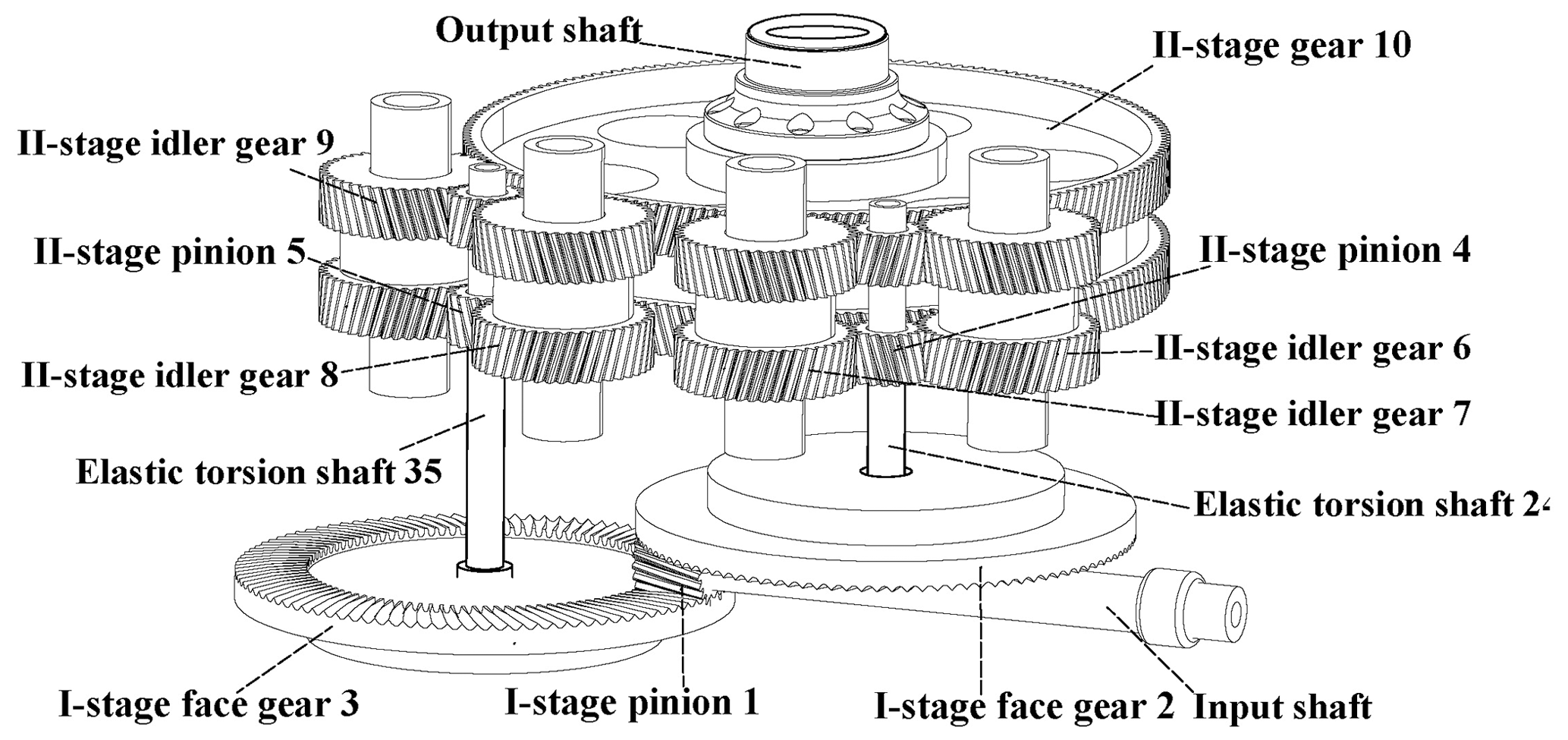
Figure 2 shows the torsional dynamic model of this system.
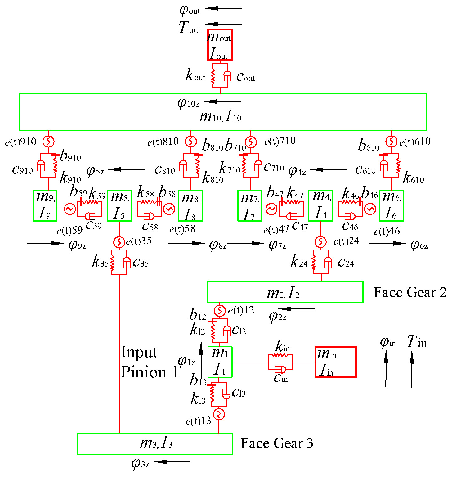
Here, Tin and Tout, kin and kout, and cin and cout are the input torque and output torque, torsional stiffness and torsional damping of input and output shafts, respectively. φin and φout, min and mout, and Iin and Iout are the torsion angle, equivalent lumped mass and moment of inertia of prime mover and loaded, respectively. kij, cij, e(t)ij and bij are the time-varying meshing stiffness, meshing damping, comprehensive error and backlash of each gear pair ij, respectively. φiz is the torsional vibration micro-displacement of each gear i. mi is the equivalent concentrated lumped-mass gear i. Ii is the moment of inertia of component i. k24 and k35 and c24 and c35 are the torsional stiffness and torsional damping of connecting shaft 24 and connecting shaft 35.
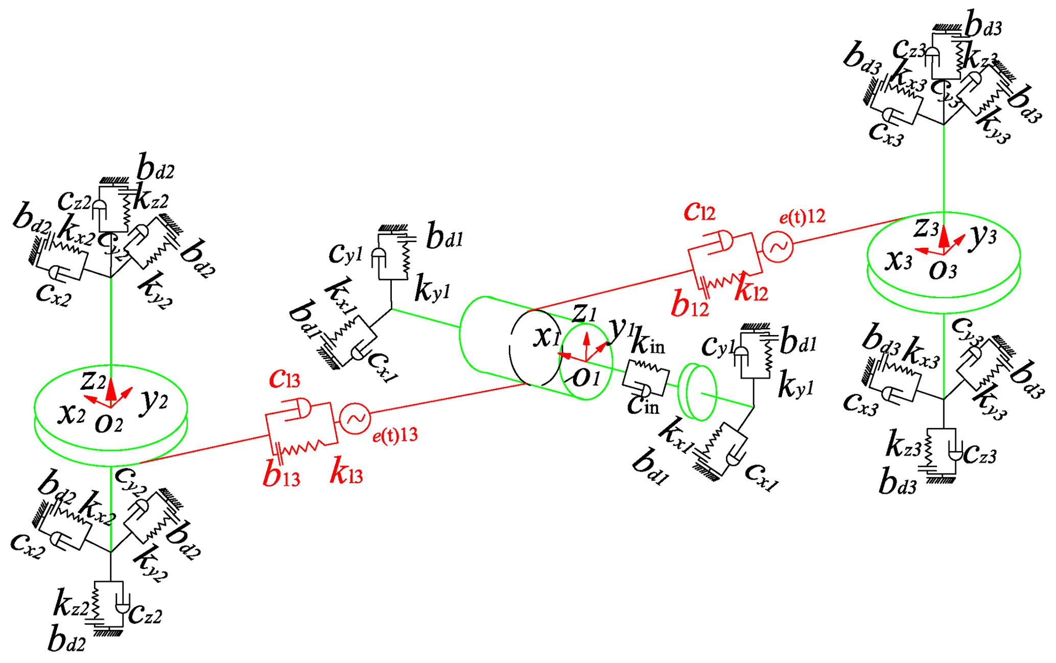
The dynamic model of one-stage face gear is established as shown in Fig. 3. kxi and kyi are the support stiffness in x direction and y direction of gear i, respectively. cxi and cyi are the support damping in x direction and y direction of gear i, respectively. bij is the average meshing backlash. bdi is the average elastic clearance. The input spur gear coordinate system is O1x1y1z1. The face gear coordinate system is O2x2y2z2 and O3x3y3z3, respectively. The z axis is the vertical upward axial direction of the face gear. The input gear shaft is perpendicular to the x direction, y direction and xz plane.
The generalized vibration displacement vector δ with 32 degrees of freedom can be expressed as Eq. (1). Here, xi, yi and zi are the transverse bending deformation of each gear in the x direction, y direction and z direction, respectively. φiz, φin and φout are the torsional angular displacement of gear i, prime mover and load components.
Force analysis of the one-stage face gear pair is shown in Fig. 4.
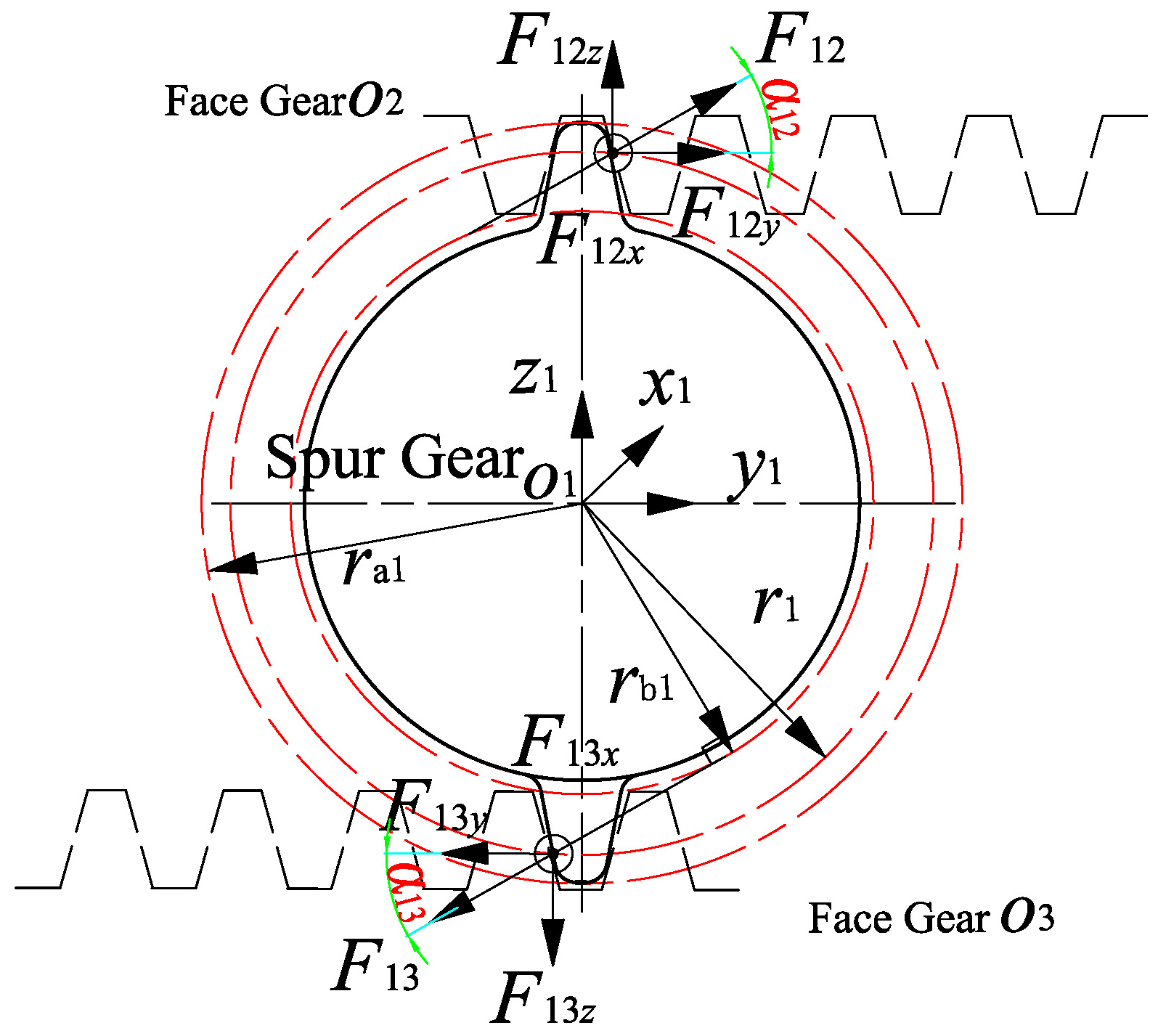
Here, r1 is the pitch radius. ra1 is the top circle radius. The vibration displacement of pinion O1 is y1 and z1 along y direction and z direction, respectively. The vibration displacement of face gear O2 and O3 along y direction and z direction is y2, y3 and z2, z3, respectively.
The meshing forces of F12 and F13 can be expressed as follows:
Based on the lumped-parameter method, the torsional vibration dynamic equation of the system is established as follows:
Here, , and are the angular acceleration of torsional vibration corresponding to gear i, prime mover and load component. , and are the angular velocity of torsional vibration corresponding to gear i, prime mover and load component. rbi represents the radius of base circle of gear i, where rb2 and rb3 represent the radius of base circle of face gear, (rL1+rL2), and rL1 is the inner radius of the face gear determined by the undercutting condition, and rL2 is the outer radius of the face gear determined by the tip sharpening condition. Ii(i=1, 2, …, 10) is the moment of inertia of each component. αn is the normal meshing pressure angle of gear pair meshing.
The angular displacement form is transformed into the linear displacement form, which can be expressed as . The mass meq,i can be expressed as .
The expressions of torsional damping c24 and c35 are as follows:
Here, ζ24 and ζ35 are the damping coefficients.
Based on Newton's second law, the lateral vibration equation of the system is established as follows:
Here, , and xi are the lateral x-direction vibration acceleration, velocity and displacement, respectively. , and yi are the lateral y-direction vibration acceleration, velocity and displacement, respectively. , and zi are the lateral z-direction vibration acceleration, velocity and displacement, respectively.
FWxi and FWyi of gear i(i=4, 5) are the component of the supporting force of the spline shaft in x and y directions. Taking pinion O4 as an example, the dynamic mechanical analysis model is shown in Fig. 5.
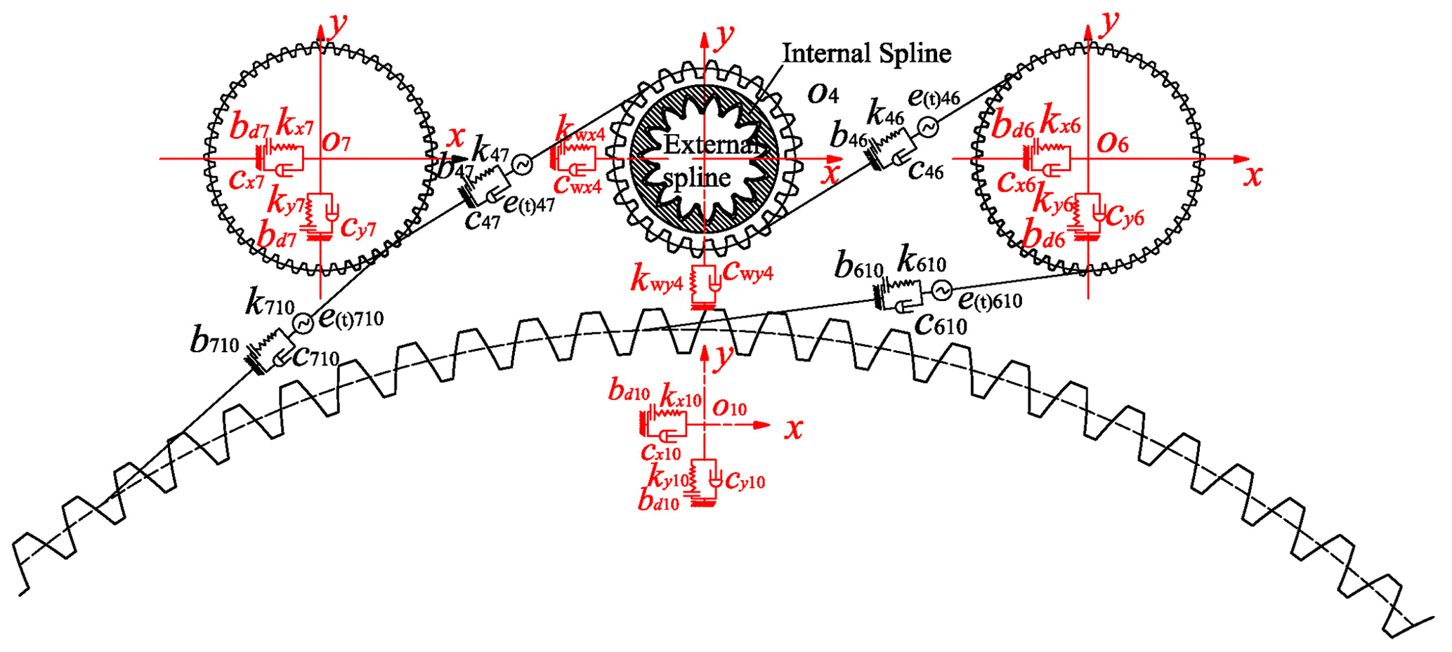
Figure 5Dynamics model of the two-stage pinion O4 under the supporting action of spline shaft.
kwxi and kwyi as well as cwxi and cwyi are bending stiffness and bending damping of spline shaft in x and y directions. Fm=τFN is the friction force between the internal and external splines in the process of transmitting torque. FN represents the normal positive pressure between the internal and external splines. τ is the coefficient of friction. , τ0 is the amplitude of friction coefficient, vs is the relative sliding speed, and sgn(vs) is the symbol function of vs. Here, τ0=0.1, sgn(vs>0)=1, τ=0.1.
Comprehensive displacement of gear i (i=4, 5) in x direction and y direction can be expressed as . Ri is the total displacement and also represents the value of spline.
The lateral bending supporting forces FWxi and FWyi can be described as follows:
Here, cm is friction damping. S1 and S2 are the radial clearance of internal and external splines. ξi is direction angle of vector (xi, yi). By combining the differential equations of dynamic torsion and transverse vibration mentioned above, the bending–torsion coupled non-linear dynamic differential equations can be obtained.
The backlash fij(xij, bij) and support clearance fxi(xi, bdi), fyi(yi, bdi) and fzi (zi, bdi) are expressed as follows:
where xij is the relative vibration displacement.
Dynamic meshing force FLij (L= I, II) can be expressed as follows:
The meshing damping cij is calculated according to the following empirical formula (Dong et al., 2018):
where kmij is the average meshing stiffness. ζgij is the damping coefficient.
Elastic force PIij and PIIij as well as meshing damping force DIij and DIIij can be expressed as follows:
Here, αIij is the positive angle between the meshing line and the center line of the one-stage face gear pair and the z axis, αIij(i=1, j=2, 3) , and γIij is the positive angle between the center line of the one-stage face gear pair and the z axis. αIIij is the positive angle between the meshing line and the center line of the two-stage cylindrical gear pair and the x axis, αIIij(i=4, 5, j=6, 7, 8, 9) , αIIij (i=6, 7, 8, 9, j=10) , and γIIij is the positive angle between the center line of the two-stage cylindrical gear pair and the x axis. rbi and rbj are the radius of base circle of gear i and j.
The eccentricity errors of one-stage face gear and two-stage cylindrical gear are shown in Fig. 6
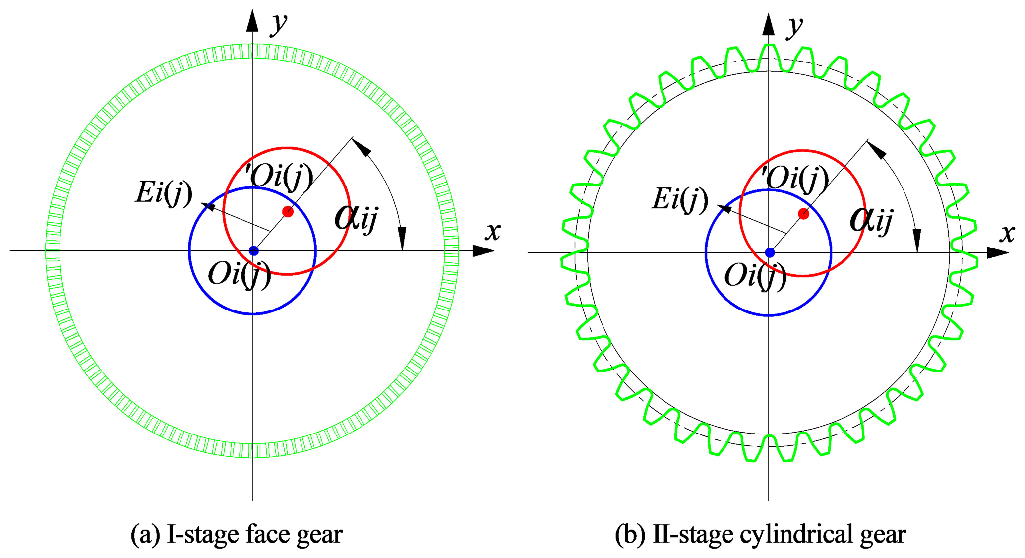

Here, Oi(j) is theoretical center position. ′Oi(j) is actual center position. αij is the angle between installation error and eccentricity error and x axis.
The equivalent meshing error e(t)ij can be expressed as follows:
Here, Ei and Ej are eccentricity error. Ai and Aj are installation error. ηi and ηj are eccentricity error phase angle. δi and δj are installation error phase angle. ωi and ωj are excitation frequency.
The dimensionless time is defined as τn=ωnt. Here, τ is the time variable of equations before dimensionless treatment. . is the average meshing stiffness of one-stage gear pair. The displacement nominal scale bc is given. The dimensionless displacement, dimensionless velocity and dimensionless acceleration are expressed as , and , respectively. The backlash and support clearance are expressed as and , respectively. Spline clearance is expressed as . The dimensionless forms of excitation frequency are , , and , respectively. The dimensionless damping variable is , the dimensionless stiffness variable is , and the dimensionless excitation force is .
The above-mentioned differential equations are normalized in dimension and solved by the Runge–Kutta method. The DLSCs of ΩI and ΩII are obtained as follows:
Here, ΩI is the one-stage DLSC. ΩII is the two-stage DLSC. Ωij(ij=12, 13, 610, …, 910) is the one-stage and two-stage DLSC of each branch. and are the average dynamic meshing force of each gear pair at one-stage and two-stage DLSC. I12 and I46 are the transmission ratio of gear pairs 12 and 46. The DLSC represents the load distribution of the system under the dynamic vibration response. The smaller the DLSC, the better the load-sharing performance of the system.
The loaded tooth contact analysis (LTCA) model of one-stage face gear pair (Li and Zhu, 2010) and two-stage gear pair (Wang et al., 2010) is shown in Fig. 7. jk is a point along the relative principal direction, k= 1, 2 for one-stage face gear, k= 1, 2, 3, 4 for two-stage gear pair. Here, the tooth surface initial clearance w is . , …, wik, …, wjk,wnk]T, , …, , n is the number of discrete points. δ is the geometric transmission error, . bj is tooth surface normal clearance (). Z is the displacement direction.
Under the action of load P, the deformation coordination condition of the elastic deformation is as follows:
(F)k is the normal flexibility coefficient matrix of the gear pair. pj() is the contact loaded at the point j of the tooth k. Apparently, the contact force pj() satisfies the following Eqs. (17)–(18):
If pjk>0, [d]jk=0. If [p]jk=0, [d]jk>0. f, P and w are known conditions. The contact forces [p]jk, final backlash [d]jk and tooth approach [Z] are unknown. The known parameters (f, P, w) and unknown parameters (p, d, Z) constitute a non-linear program model. According to the tooth approach Zk, the objective function is established as follows:
The objective function equation can be expressed as follows:
Xj (j=1, 2, …, 2n+1) is the artificial variables, (X) = (X1, …, X2n)T, (e) = 1.
The transmission error of the gear bearing in meshing is mainly composed of three parts of the geometric transmission error δ1, the bending deformation δ2 and the contact deformation δ3. The geometric transmission errors δ1 can be expressed as δ1(T(k))=a. The bending deformation errors δ2 can be expressed as δ2(T(k))=bT (k). The function relationship between the contact deformation δ3(T(k)) and the loaded T(k) can be expressed as .

The relational expression of the integrated angular deformation Δφij(Tij(k)) and torque Tij(k) of the gear pairs of the system can be expressed as follows:
Here, a, b and c are the constant terms in the formula. Tij(k) is the torque of the kth meshing position.
By solving the LTCA equations, the load transmission error Δφij[0.1Tij[k]], Δφij[0.5Tij[k]] and Δφij[0.9Tij[k]] can be obtained. The coefficient a, b and c can be obtained by taking the obtained transmission error into Eq. (17).
The time-varying meshing stiffness kij(k) can be obtained as follows:
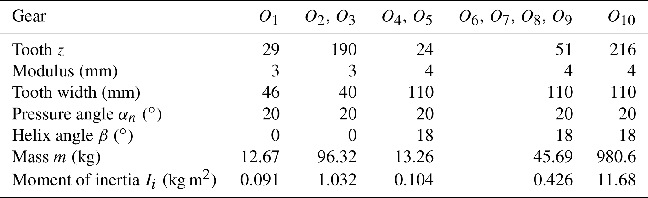
Input power P=2000 kW, input speed n=8780 r min−1, installation error Ai=50 µm, eccentricity error Ei=50 µm, and one-stage face gear backlash µm. Two-stage gear pair backlash µm. Spline clearance S2=50 µm. Support clearance bdi=10 µm. The gear parameters are shown in Table 1.
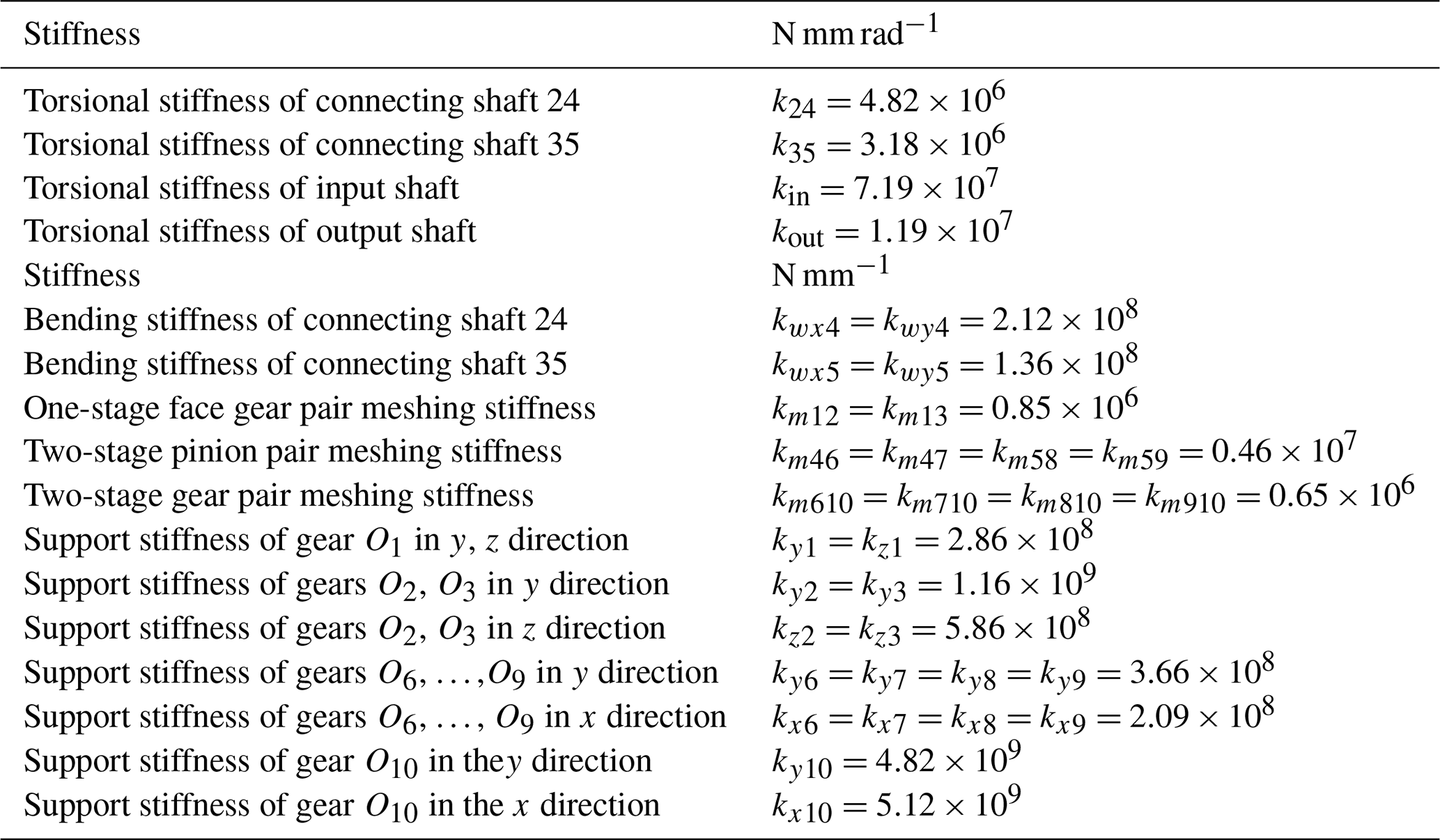
The parameters of equivalent support stiffness, torsional stiffness and meshing stiffness are shown in Table 2. The support stiffness is calculated according to GB/T 3073-1996.
The parameters of equivalent supporting damping, torsional damping, and meshing damping are shown in Table 3.
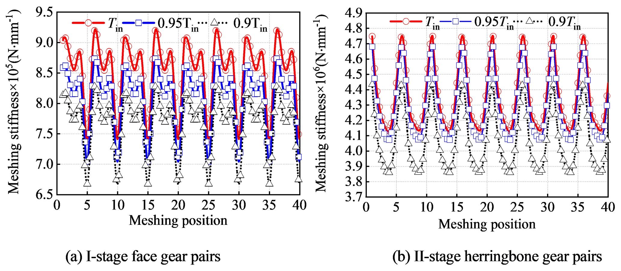
The calculated time-varying meshing stiffness curve is shown in Fig. 8. The meshing stiffness fluctuation range of one-stage face gear pairs is (7.46 × 10⁵–9.27 × 10⁵) N mm−1. The meshing stiffness fluctuation range of two-stage idler gear pairs is (3.77 × 10⁶–4.78 × 10⁶) N mm−1. The meshing stiffness fluctuation range of two-stage big gear pair is (6.17 × 10⁶–6.68 × 10⁶) N mm−1. Due to the different meshing stiffness of each meshing position of the tooth surface, the DLSC of different meshing positions will be changed slightly.
6.1 Effect of installation and eccentricity errors on the DLSC
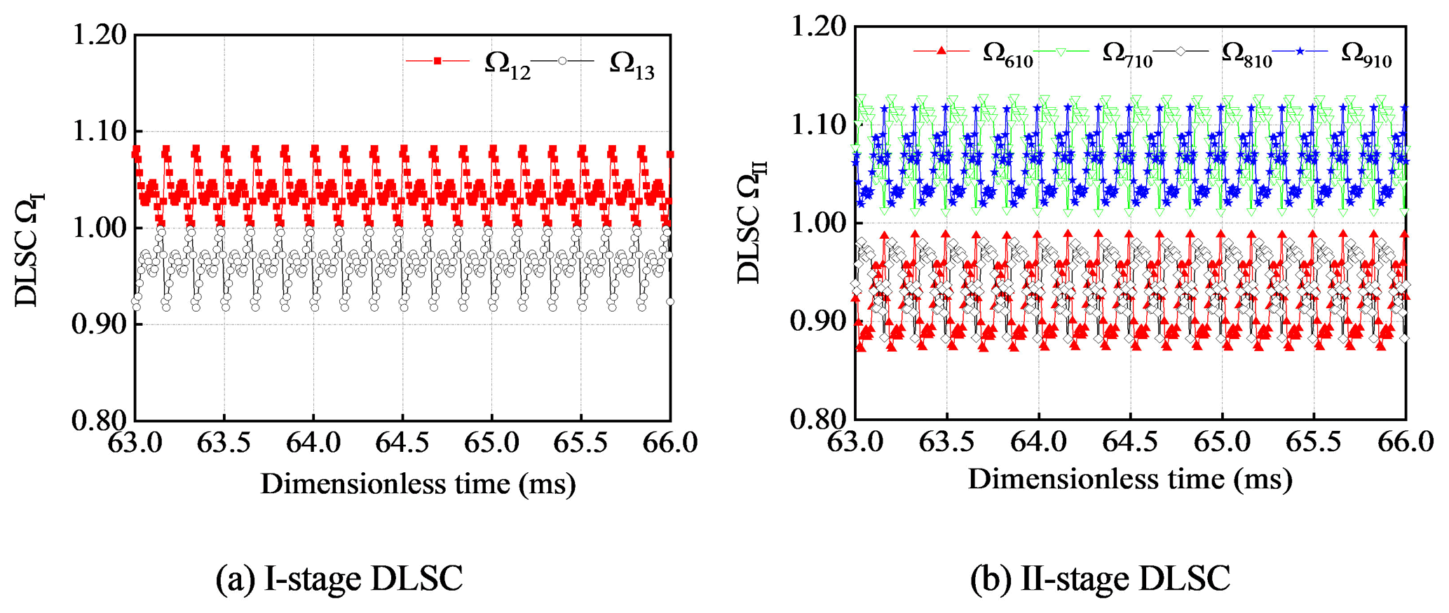
Under the combined action of installation error and eccentricity error, the DLSC presents periodic changes with time, as shown in Fig. 9. The one-stage DLSC is Ω12=1.0383 and Ω13=0.9617. Torque T12 and T13 are fluctuated around in 1129.33 N m and 1046.0 N m. Torque distribution is 51.92 % and 48.09 %. The two-stage DLSC is Ω610=0.914, Ω710=1.086, Ω810=0.948 and Ω910=1.052. Torque T610, T710, T810 and T910 are fluctuated around in 6920.5, 8222.9, 7178.1 and 7965.4 N m, respectively. The influence of one-stage gear pair 12 and two-stage gear pair 710 on the load-sharing characteristics is maximum impact. The overall DLSC is ΩZ=1.086. The DLSCs of the system are ΩI=1.0383 and ΩII=1.0860, respectively. The DLSC changed periodically with time.
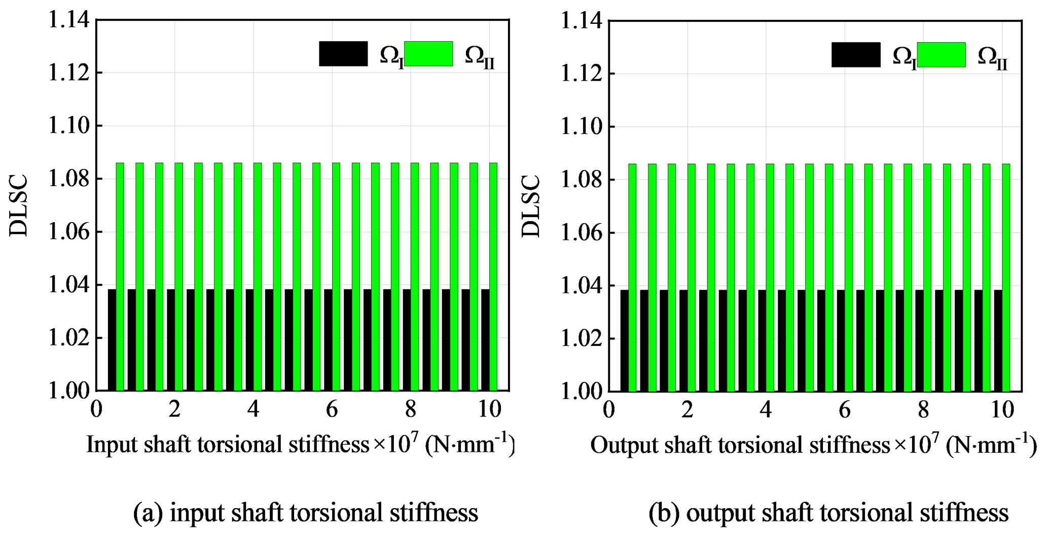
Figure 16Influence of input and output shaft torsional stiffness on dynamic load-sharing coefficient.
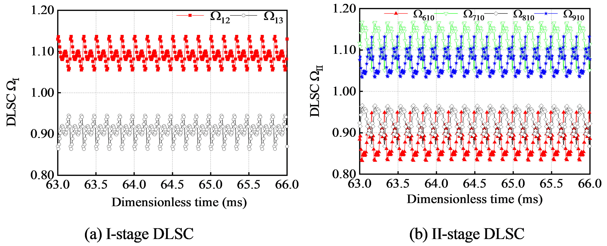
Other parameters remain unchanged, when given µm. The DLSC under the combined action of errors is shown in Fig.10. The one-stage DLSCs of ΩI change from 1.0383 to 1.0921. The two-stage DLSCs of ΩII change from 1.0860 to 1.1220. The one-stage face gear backlash has a great influence on the one-stage DLSC and a little influence on the two-stage DLSC.
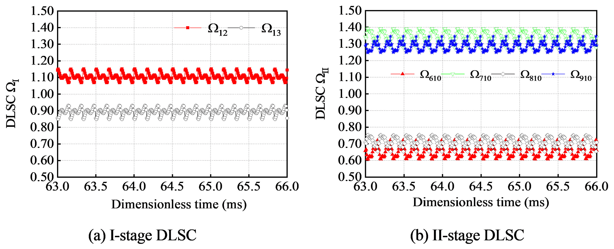
Other parameters remain unchanged, when given one-stage backlash µm, two-stage backlash µm. The DLSC under the combined action of errors is shown in Fig. 11. The one-stage DLSCs of ΩI change from 1.0383 to 1.131. The two-stage DLSCs of ΩII change from 1.0860 to 1.3507. Under the combined action of the errors, the load-sharing performance becomes worse with the decrease of the backlash.
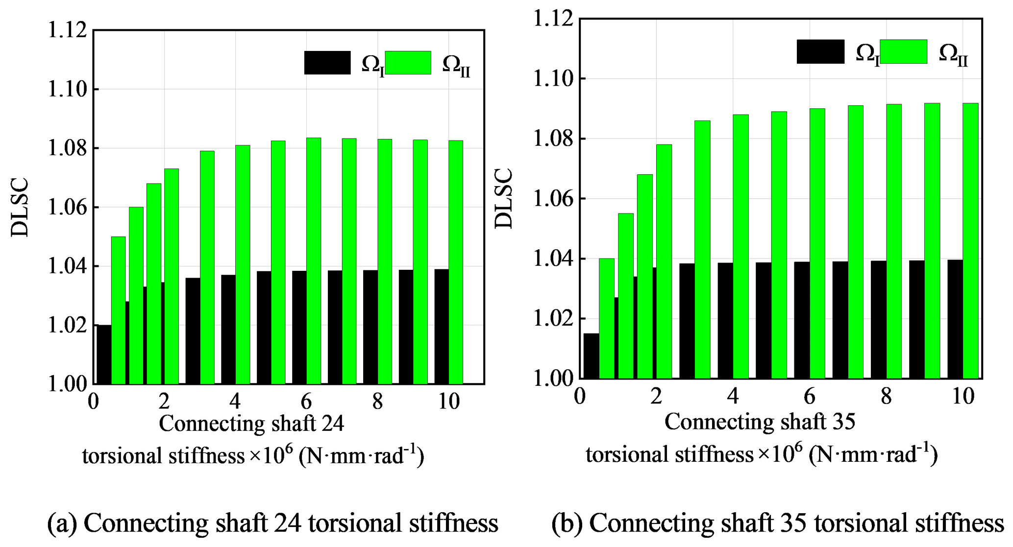
Figure 17Influence of torsional stiffness of connecting shaft on the dynamic load-sharing coefficient.
The DLSC changes with the errors as shown in Fig. 12. Figure 12a and b show the influence of installation errors on the DLSC, and Fig. 12c and d show the influence of eccentricity errors on the DLSC. When the given error range is from 0–50 µm, the influence range of installation error on one-stage DLSC is 1.0003–1.0049, the influence range of installation error on two-stage DLSC is 1.0001–1.1605, the influence range of manufacturing error on one-stage DLSC is 1.0005–1.0125, and the influence range of manufacturing error on two-stage DLSC is 1.0005–1.1160. The installation errors and eccentricity errors have less influence on the one-stage DLSC and more influence on the two-stage DLSC. The eccentricity errors are more sensitive than the installation errors on the one-stage DLSC.
6.2 Effect of backlash, support clearance and spline clearance on the DLSC
The change of the DLSC ΩI and ΩII with the backlash is shown in Fig. 13. The one-stage DLSC ΩI changed strongly with the increase of one-stage backlash, which changed from 1.121–1.016. The influence of one-stage backlash on the two-stage DLSC ΩII changes little, which changed from 1.088–1.075. The influence of two-stage backlash on two-stage DLSC is more sensitive. With the increase of backlash, the DLSC gradually decreases from 1.268–1.021. The influence of two-stage backlash on one-stage DLSC is less, which changed from 1.045–1.035. In a certain range, the one-stage DLSC and two-stage DLSC decrease with the increase of the backlash. The backlash can compensate the deformation caused by the errors and improve the load-sharing performance to a certain extent.
When other parameters remain unchanged, the changes with the one-stage and two-stage DLSC support clearance and are shown in Fig. 14. With the increase of one-stage support clearance, the DLSC decreases gradually. ΩI changed from 1.0402–1.0341 and ΩII changed from 1.0870–1.0842. With the increase of two-stage support clearance, the DLSC ΩI decreased from 1.0408–1.0297, and ΩII decreased from 1.0879–1.0801. The influence of the support clearance on the DLSC is small.
Figure 15 shows the curves of one-stage and two-stage DLSC with the spline clearance from 0–450 µm. With the change of spline clearance, one-stage DLSC does not change at 1.0383, while two-stage DLSC changes from 1.0921–1.012. The influence of spline clearance on the one-stage DLSC is almost unchanged and has a great impact on the two-stage DLSC. When the spline clearance is 0 mm, it is equivalent to the bending stiffness of the spline shaft to provide support. The DLSC is Ω610=0.9079, Ω710=1.0921, Ω810=0.9432 and Ω910=1.0568. When the spline clearance is greater than the total displacement R5 (0.271 mm), the two-stage pinion O5 is in a fully floating state. When the spline clearance is greater than the total displacement R4 (0.382 mm), the two-stage pinion O4 and O5 enter a full floating state at the same time, and the load-sharing characteristic is improved, and the DLSC is stable at ΩII=1.012. Among them, the DLSCs of two-stage gear pairs are Ω610=0.9861, Ω710=1.0139, Ω810=0.988 and Ω910=1.012. Two-stage pinion O4 and pinion O4 are independent in floating behavior.
6.3 Effect of torsional stiffness and support stiffness on the DLSC
The influence curve of DLSC of input shaft and output shaft is shown in Fig. 16 when the torsional stiffness changed from (0.5–10.0) × 107 N mm rad−1. Input shaft and output shaft have almost no influence on the dynamic load-sharing coefficient of the system. This conclusion is consistent with the conclusion of the influence of torsional stiffness on the load-sharing coefficient of power split transmission system analyzed in Jin et al. (2019a, b).
Other parameters remain unchanged, and the DLSC changes with the torsional stiffness of connecting shaft 24 and connecting shaft 35 at (0.5–10.0) × 106 N mm rad−1, as shown in Fig. 17. With the increase of the torsional stiffness of connecting shaft 24 and connecting shaft 35, the DLSC gradually becomes larger, the average load characteristics become worse, and the influence trend is the same. The influence of torsional stiffness on the two-stage DLSC is more obvious than that of the one-stage DLSC. Although the geometry of the system is symmetrical, but because of the different direction of meshing force and the geometry of the connecting axis, the force situation is not consistent, resulting in a certain difference in the dynamic load-sharing characteristics.
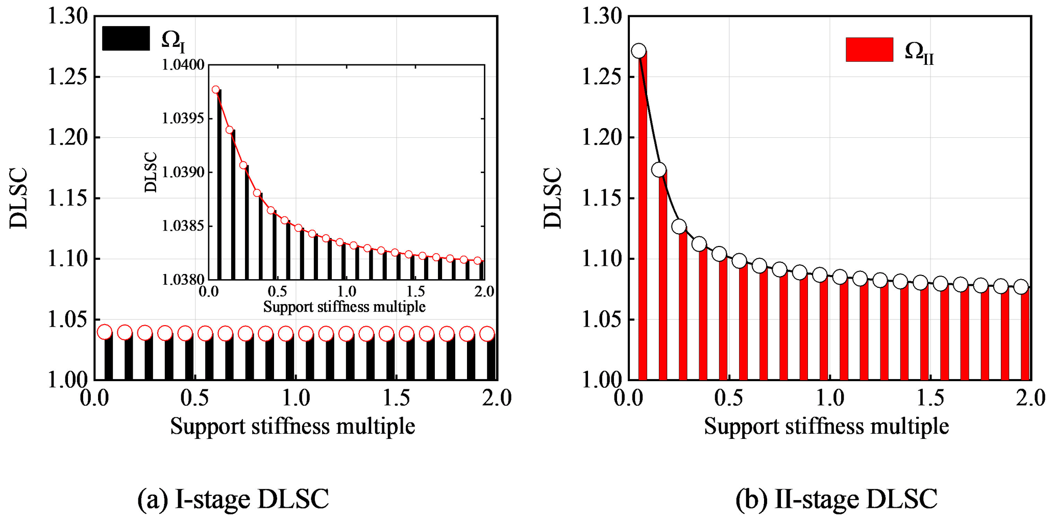
With other parameters unchanged, the overall support stiffness of each gear shown in Table 2 is (2–0.05) times that of the change, and the influence curve of the overall support stiffness on the DLSC of the system is shown in Fig. 18.
With the decrease of the support stiffness multiple, the DLSC becomes larger, and the dynamic performance becomes worse. Especially when the overall support stiffness multiple is (0.5–0.05), the influence of the dynamic load-sharing coefficient of two-stage DLSC is stronger, and the change of ΩII is from 1.0763–1.2714, but it has little influence on the dynamic load-sharing coefficient of one-stage DLSC, and the change of ΩI is from 1.0381–1.0397.
In this paper, a new configuration of face gear dual-power split transmission system is proposed, and the effects of backlash, support clearance, error, torsional stiffness and support stiffness on dynamic load-sharing characteristics are analyzed, which provides the theoretical basis for further optimization design of vibration stability. The conclusions are as follows:
-
With the increase of backlash, the DLSCs gradually decrease and tend to be stable. The two-stage DLSC has a great influence with the change of backlash. Increasing the backlash of each two-stage gear pair properly is conducive to improving the load-sharing characteristics. With the increase of the support clearance, the DLSC decreases, but the change value is small. The increase of the support clearance has little effect on the improvement of the dynamic load-sharing characteristics. The increase of spline clearance is beneficial to the improvement of even load characteristics.
-
With the increase of installation error and eccentricity error, the DLSC is larger and the system load-sharing performance is worse. The installation error and eccentricity error of each gear in level 2 have the greatest influence on the dynamic load-sharing coefficient. The installation and manufacture of each gear in level 2 should be considered in the design.
-
With the increase of torsional stiffness, the DLSC increases, and the load-sharing characteristics become worse. The change trend of the dynamic load-sharing coefficient is relatively consistent between the connecting shaft 24 and the connecting shaft 35. In the optimal design of the load-sharing structure, the flexible connecting shaft meeting the strength should be selected to improve the load-sharing performance. With the decrease of support stiffness, the change two-stage DLSC is more intense. Choosing a reasonable rigid support in the optimal design is conducive to ensuring a better load-sharing performance.
All data, models, and code generated or used during the study appear in the article.
The raw/processed data required to reproduce these findings cannot be shared at this time as the data also form part of an ongoing study.
All authors contributed to the study conception and design. Material preparation, data collection and analysis were performed by HD, HQZ, XLZ and LLD. The first draft of the manuscript was written by HD, and all authors commented on previous versions of the manuscript. All authors read and approved the final manuscript.
The authors declare that they have no conflict of interest.
This research has been supported by the National Natural Science Foundation of China (grant no. 51705390), the Innovation Capability Support Program of Shaanxi (grant no. 2020KJXX-016), the Scientific Research Program Funded by Shaanxi Provincial Education Department Program (grant no. 20JC015), the Principal Foundation Project of Xi'an Technological University (grant no. xgpy200201), and the Natural Science Foundation of Shaanxi Province (grant no. 2021JM-428).
This paper was edited by Francisco Romero and reviewed by two anonymous referees.
Bao, H. Y., Li, F. B., and Lu, F. X.: Analysis of dynamic characteristics of a variable speed helicopter transmission system, Journal of Central South University (Science and Technology), 50, 2403–2416, https://doi.org/10.11817/j.issn.1672-7207.2019.10.009, 2019 (in Chinese).
Dong, H., Fang, Z. D., and Hu, Y. H.: Study on the load-sharing characteristics of an aeronautical II-stage five-branching planets gear train based on the loaded tooth contact analysis, Math. Probl. Eng., 5, 1–18, https://doi.org/10.1155/2018/5368294, 2018.
Dong, J. X., Tang, J. Y., and Hu, Z. H.: Investigation of assembly, power direction and load-sharing in concentric face gear split-torque transmission system, Meccanica, 54, 2485–2506, https://doi.org/10.1007/s11012-019-01078-0, 2019.
Handschuh, R. E., Lewicki, D. G., and Heath, G. F.: Experimental evaluation of face gears for aerospace drive system applications, San Diego, NASA Technical Memorandum, 107227, available at: https://www.researchgate.net/publication/24289872_Experimental_Evaluation_of_Face_Gears_for_Aerospace_Drive_System_Applications (last access: 20 May 2021), 1996.
Heath, G. F. and Bossler, J. R. B.: Advanced rotorcraft transmission (ART) program-final report, Lewis, NASA Contractor Report, 191057, https://doi.org/10.2514/6.1991-1906, 1993.
Jin, G. H., Ren, W., and Zhu, R. P.: Influence of torsional stiffness on load-sharing characteristics of power split transmission system, J. Aerosp. Power, 34, 2478–2489, https://doi.org/10.13224/j.cnki.jasp.2019.11.020, 2019a (in Chinese).
Jin, G. H., Ren, W., and Zhu, R. P.: Influence of backlash on load-sharing and dynamic load characteristics of twice split torque transmission system, J. Vib. Eng. Technol., 7, 565–577, https://doi.org/10.1007/s42417-019-00150-z, 2019b.
Krantz, T. L.: A method to analyze and optimize the load-sharing of split path transmissions, NASA Technical Memorandum, 107201, available at: https://www.researchgate.net/publication/24290120_A_Method_to_Analyze_and_Optimize_the_Load_Sharing_of_Split_Path_Transmissions (last access: 20 May 2021), 1996a.
Krantz, T. L. and Delgado, I. R.: Experimental study of split-path transmission load-sharing, NASA Technical Memorandum, 107202, available at: https://ntrs.nasa.gov/citations/19960035852 (last access: 20 May 2021), 1996b.
Li, Z. M. Q. and Zhu, R. P.: Load tooth contact analysis on face-gear driver, Journal of Nanjing University of Aeronautics & Astronautics, 42, 219–223, https://doi.org/10.16356/j.1005-2615.2010.02.007, 2010 (in Chinese).
Mo, S., Yue, Z. X., and Feng, Z. Y.: Analytical investigation on load-sharing characteristics for multi-power face gear split flow system, P. I. Mech. Eng. C, 234, 095440621987695, https://doi.org/10.1177/0954406219876954, 2019.
Peng, M., Desmidt, H. A., Saribay, Z. B., and Smith, E. C.: Parametric instability of face-gear drives due to meshing loads, J. Am. Helicopter. Soc., 61, 1–13, https://doi.org/10.4050/JAHS.61.042006, 2016.
Robert, F. H. and James, J. Z.: Current research activities in drive system technology in support of the NASA rotorcraft program, NASA Technical Memorandum, 214052, available at: https://www.researchgate.net/publication/289464290_Current_research_activities_in_drive_system_technology_in_support_of_the_NASA_rotorcraft_program (last access: 20 May 2021), 2006.
Stevens, M. A., Handschuh, R. F., and Lewicki, D. G.: Variable/Multispeed rotorcraft drive system concepts, NASA Technical Memorandum, 215456, available at: https://ntrs.nasa.gov/citations/20090019132 (last access: 20 May 2021), 2009.
Wang, C., Fang, Z. D., and Gu, J. G.: Loaded tooth contact analysis of double helical gears and experimental investigation, J. Aerosp. Power, 25, 718–722, https://doi.org/10.13224/j.cnki.jasp.2010.03.005, 2010 (in Chinese).
Wang, Q. B., Tang, J. Y., and Tan, W. Z.: Load-sharing performance of two branches split-torque transmission system with cylindrical gears, J. Aerosp. Power, 34, 1598–1606, https://doi.org/10.13224/j.cnki.jasp.2019.07.021, 2019 (in Chinese).
Wang, R. F., Zhao, N., and Tao, L.: Floating shaft load-sharing method for face-gear split torque transmission system, Res. J. Appl. Sci. Eng. Technol., 5, 3386–3392, https://doi.org/10.19026/rjaset.5.4584, 2013.
Zhang, L. L. and Zhu, R. P.: Static load-sharing behavior of herringbone planetary gear train with floating composite ring gear, Journal of Central South University (Science and Technology), 49, 1126–1134, https://doi.org/10.11817/j.issn.1672-7207.2018.05.014, 2018 (in Chinese).
- Abstract
- Introduction
- Transmission system configuration and dynamic model establishment
- Establishment of differential equations of system dynamics
- DLSC calculation
- Time-varying meshing stiffness calculation based on LTCA
- Example analysis
- Conclusions
- Code and data availability
- Data availability
- Author contributions
- Competing interests
- Financial support
- Review statement
- References