the Creative Commons Attribution 4.0 License.
the Creative Commons Attribution 4.0 License.
 | 12 May 2021
Industrial robot-based system design of thickness scanning measurement using ultrasonic
Haibo Liu
Baoliang Liu
Pingping Li
Tianran Liu
Te Li
Yongqing Wang
Wall thickness is one of the core indicators for measuring the quality of large thin-walled parts such as rocket siding and aircraft skin. However, the traditional handheld thickness measurement method has high labor intensity, low efficiency and poor accuracy consistency. Therefore, an in situ ultrasonic automatic scanning thickness measurement method for large thin-walled parts based on industrial robots is proposed. This “industrial robot + ultrasound” integrated function is a compact system, and a set of innovative methodological or technical solutions is presented, such as (i) TCP and UDP communication protocols being constructed to realize a high-speed and stable communication relationship between the upper computer, robot motion controller and ultrasonic thickness measurement unit; (ii) a coupling gap adjustment method based on eddy-current sensors being adopted to ensure the adaptability of the ultrasonic probe to surface topography of the measured part during scanning measurement; and (iii) a multi-sensor coordinate unified model and coupling gap state discrimination model being established for robot-aided thickness measurement. To verify the feasibility of the proposed method, a series of calibrations and experiments were designed based on the KUKA robot platform and the developed ultrasonic pulse measurement system. Finally, the industrial robot-based ultrasonic thickness scanning measurement has been built and tested for performing the measurement of a rocket tank wall.
- Article
(2407 KB) - Full-text XML
- BibTeX
- EndNote


Large thin-walled parts are widely used in important equipment in the fields of automobiles, aerospace, defense and others because of their light weight, high strength and strong carrying capacity (Kolluru et al., 2013). The remaining wall thickness must meet the processing requirements of equal wall thickness or variable wall thickness according to certain rules (Lian et al., 2019). Nevertheless, it is difficult to finish the wall thickness at one time because of the large size, complex shape and low rigidity of the parts (Liu et al., 2015). Therefore, the wall thickness of the thin-walled part in the machining gap should be measured in order to modify the machining parameters according to the measurement results for re-machining (Huang et al., 2018).
However, there are many points to be measured for large thin-walled parts, and the requirements for thickness measurement accuracy are high (Higuchi et al., 2005). The results of manual handheld measurement (Han et al., 2016; Huang et al., 2018) are of low accuracy, low efficiency, poor stability and high labor intensity, which are difficult for meeting the requirements. Although the offline automatic measurement method represented by a coordinate measuring machine (CMM) (Pfeifer et al., 2005) can overcome many shortcomings of the manual handheld measurement method, the process of clamping large thin-walled parts to the CMM brings many deformation and positioning errors. For single-side thickness measurement of parts, ultrasonic is the preferred measurement method in the industrial field because of its transmission and reflection characteristics of the interface (Kozlov et al., 1997; Li et al., 2010).
The ultrasonic thickness measurement system with online integration has advantages in improving measurement quality and efficiency, reducing labor and comprehensive manufacturing cost (Huang et al., 2012; Pfeifer et al., 2005). However, contact ultrasonic thickness measurement (Hsu et al., 1994) is carried out by point-by-point contact with the part, which easily leads to part deformation and probe wear due to improper contact state control. Therefore, the contactless method (Lian et al., 2019) should be adopted to make up for the problems of the former, such as the difficulty in adjusting contact force and low measuring efficiency, and is more suitable for integration with equipment to realize thickness measurement. For example, Pfeifer and Benz (2002) and Pfeifer et al. (2005) integrated the ultrasonic thickness measurement device into the conventional computerized numerical control (CNC) lathe, and the ultrasonic sensor scanned along the generatrix of the cylindrical parts, with the measurement accuracy up to 10 µm.
The robot platform is an effective means of achieving various requirements of position and attitude measurement in space because of the advantages of good flexibility and a high degree of automation (Alatorre et al., 2018). Industrial robots are widely used in manufacturing, visual inspection and in situ repair fields at present (Cai et al., 2019; Wang et al., 2018), as tendon-driven continuum robotics is supposed to be a promising tool with high manoeuvrability in testing, navigating and machining within confined workspaces (Dong et al., 2019). However, due to the particularity of the ultrasonic scanning signal and the requirement of stable coupling of commercial piezoelectric transducers, the integration technology of an ultrasonic measurement system and a robot platform is immature. Burghardt et al. (2017) conducted an alternative robot-assisted vane wall thickness measurement, which was done with the ABB IRB 140 robot and by employing the UTT method. Xiao et al. (2019) proposed a novel dual-robot mirror milling system for weak rigid large thin-walled aerospace parts, but the actual measuring wall thickness was inspected by a manual ultrasonic thickness gauge to validate machining quality. Enjikalayil Abdulkader et al. (2020) presented an autonomous steel plate thickness inspection robot using an ultrasound technique, called Sparrow, for the ship hull maintenance task. Therefore, in order to realize the precise and automatic measurement of the thickness distribution of the large thin-walled part, the ultrasonic measurement device should be integrated into the industrial robot. Finally, the thickness distribution of the large thin-walled part is obtained by programming different measurement paths and combining the ultrasonic thickness measurement results with the robot's end space coordinates.
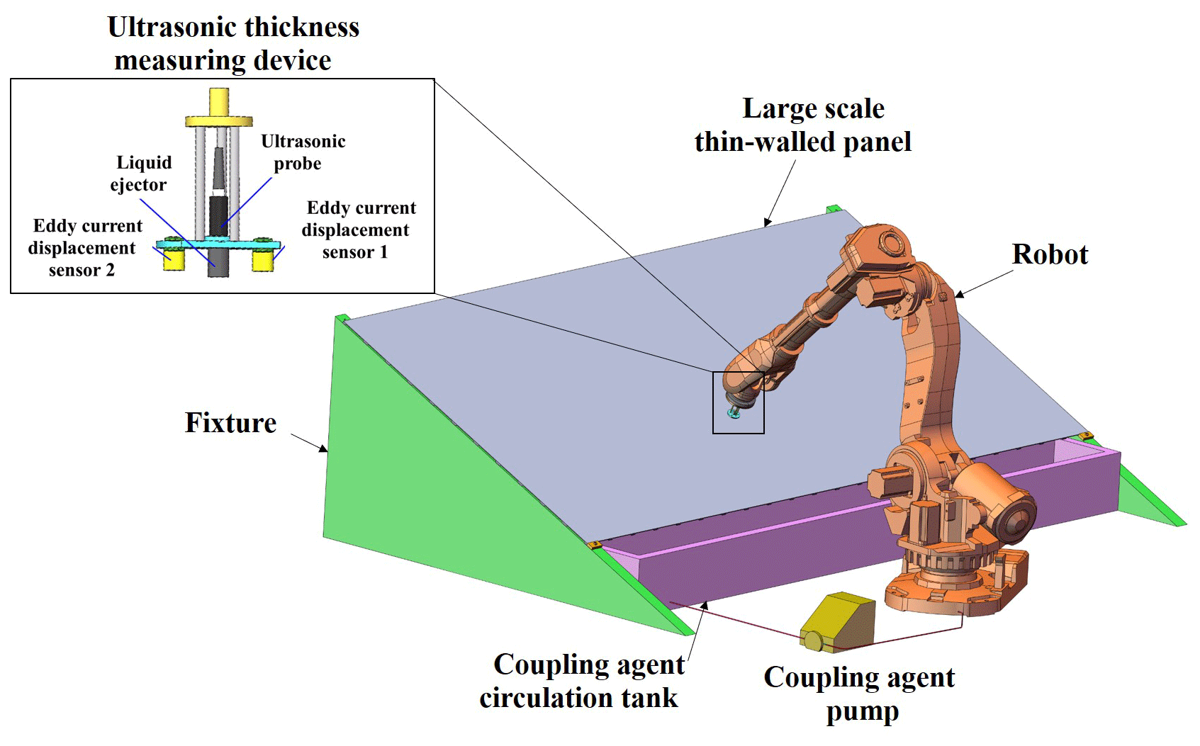
The ultrasonic automatic thickness measurement process for large thin-walled parts is shown in Fig. 1. Before the measurement, the parts are clamped by special clamps and the ultrasonic thickness measurement device is integrated into the executive end of the industrial robot. In order to plan the scanning measurement path of the ultrasonic probe, the motion path of each joint of the robot is planned based on the kinematic equation. In the measurement, the industrial robot drives the ultrasonic thickness measurement device to conduct contactless scanning on one side of the work piece according to the trajectory, and real-time monitoring is carried out to prevent the collision between the measurement device and the work piece. In order to ensure the coupling state, the coupling agent in the circulation tank is automatically filled on the surface of the probe and the wall plate through the peristaltic pump and filter device to form the coupling agent circulation system. The measurement system automatically collects and calculates the thickness according to a certain sampling frequency and finally obtains the thickness distribution data of a large thin-walled panel.
The ultrasonic measurement system mainly includes a system main control module, upper computer module, robot motion control module, ultrasonic transmitting/receiving module, I/O module, etc., as shown in Fig. 2, which can realize the communication between an ultrasonic automatic thickness measurement system and a robot motion control system, automatic ultrasonic signal acquisition, intelligent data processing, human–computer interaction and other functions.
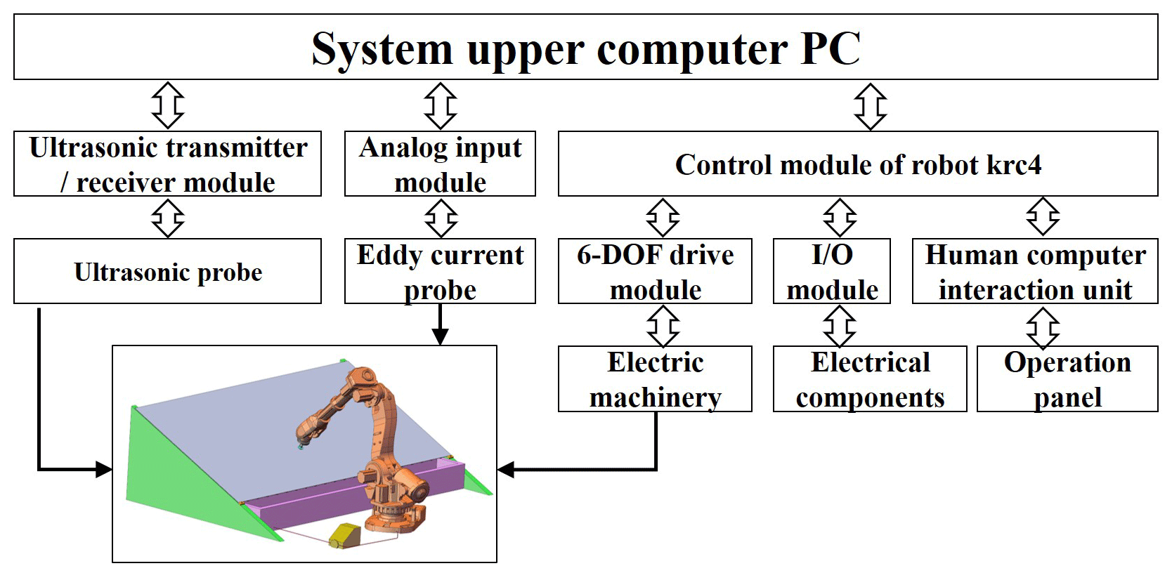
Figure 2Module decomposition of an industrial robot-aided ultrasonic thickness measurement system.
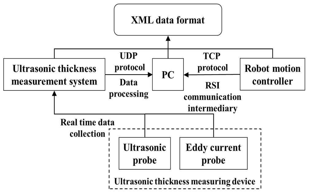
In order to ensure the communication between each module of the industrial robot-assisted ultrasonic thickness measurement system, the high-speed and stable communication relationship between the upper computer and the robot motion controller and the ultrasonic thickness measurement unit was constructed using the Transmission Control Protocol (TCP) and User Datagram Protocol (UDP) communication protocols, as shown in Fig. 3.
The communication between the upper computer and the robot motion controller requires higher reliability of data transmission. If the data loss or error will lead to the robot's global motion disorder and reduce the thickness measurement accuracy, a highly reliable TCP communication protocol is selected, which provides data verification and a transmission mechanism to ensure that the data can reach the other party accurately. The communication flow between the upper computer and the robot motion controller, the ultrasonic thickness measuring unit, is shown in Fig. 4.
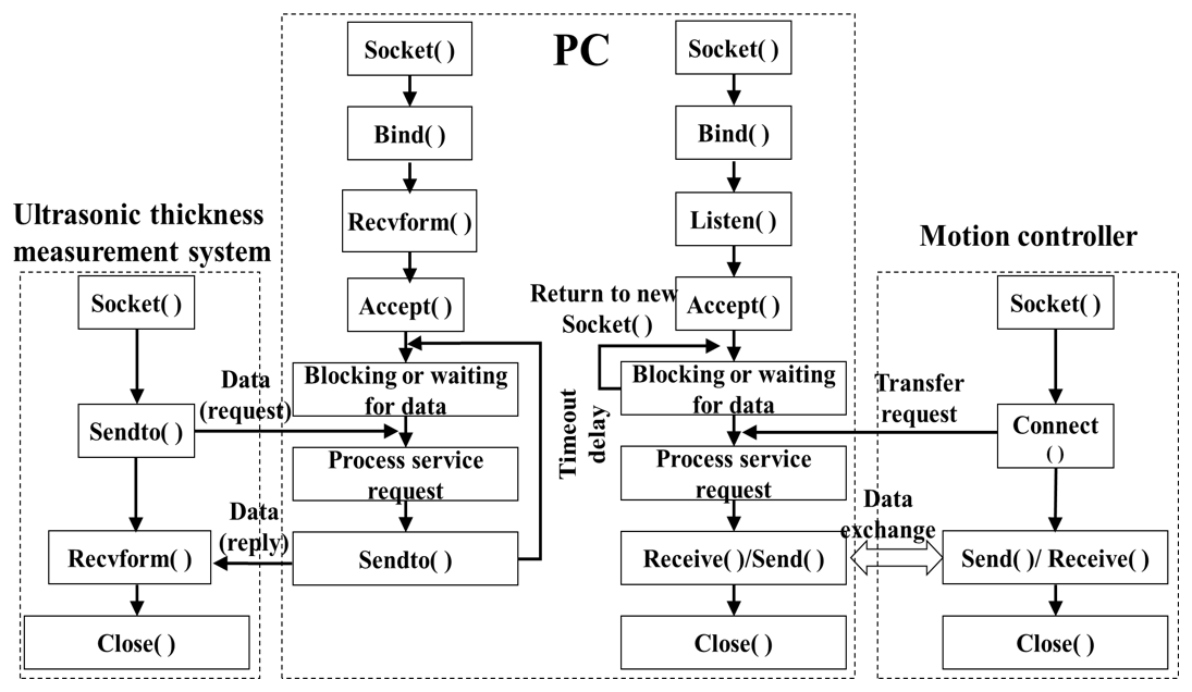
Figure 4Communication flow chart of the upper computer and robot motion controller system communication scheme.
Due to the irregular deformation of the panel and the unknown mathematical model, the ultrasonic coupling gap is unstable in the process of scanning measurement. The probe position must be adjusted adaptively to ensure that the measuring device does not collide with the panel and maintains a good coupling state. A follow-up displacement measuring device is attached to the front section of the ultrasonic probe, which is prior to the ultrasonic sensor passing through the measured surface in the whole scanning measurement process. The position information of the panel surface is read and fed back to the control system to realize the adaptive adjustment of the coupling gap during the ultrasonic contactless scanning thickness measurement.
When the probe scans along the +x axial direction, the distance between the bottom center of the eddy-current displacement sensor and the measured panel surface is De, and the distance between the bottom center of the ultrasonic sensor and the measured panel surface is Du. Considering the near-field length of the ultrasonic sensor, the structure of the injector and the influence of the coupling gap on the ultrasonic echo amplitude and the thickness measurement error during the ultrasonic contactless scanning thickness measurement, the threshold range of the coupling gap . The ranging value of the measuring point shall meet the following relationship, which is obtained through experimental calibration.
where H is the relative distance between the eddy-current displacement sensor bottom and the ultrasonic sensor injector bottom.
In the process of robot-aided scanning measurement, the coupling gap state between the measuring point and the ultrasonic sensor is identified in real time by substituting the current measuring point distance De of the eddy-current sensor on the tested panel into Eq. (1). If the measuring point is the point to be adjusted, the robot end needs to be adjusted to shift the ultrasonic thickness measuring device up and down along the z-axis direction when the ultrasonic sensor reaches the measuring point, so that the coupling gap falls back into the threshold range. After identifying the measuring point as an adjustment point and the corresponding “adjustment value” of the ultrasonic sensor, it is also necessary to generate an “adjustment path” to guide the ultrasonic sensor movement to the measuring point, so as to realize the smooth control of the ultrasonic contactless scanning thickness measurement process.
The ultrasonic thickness measurement device used in the proposed method involves multiple sensors, and the measurement coordinate system of each sensor needs to be established separately and unified to the reference coordinate system through coordinate conversion before the measurement, so that the measurement results of each sensor can be converted to the reference coordinate system for data processing in the measurement process. As shown in Fig. 5, there are four coordinate systems in the measurement system based on a six-axis industrial robot: reference coordinate system OwXwYwZw, robot coordinate system obxbybzb, flange coordinate system ofxfyfzf and sensor coordinate system osxsyszs. The relationship between the measured point in the sensor coordinate system and the reference coordinate system is
where Pw and Ps are the measurement points in the base coordinate and the sensor coordinate, respectively, wTb is the transformation matrix from the robot coordinate system to the reference coordinate system, bTf is the transformation matrix from the flange coordinate system to the robot coordinate system, and fTs is the transformation matrix from the sensor coordinate system to the flange coordinate system.
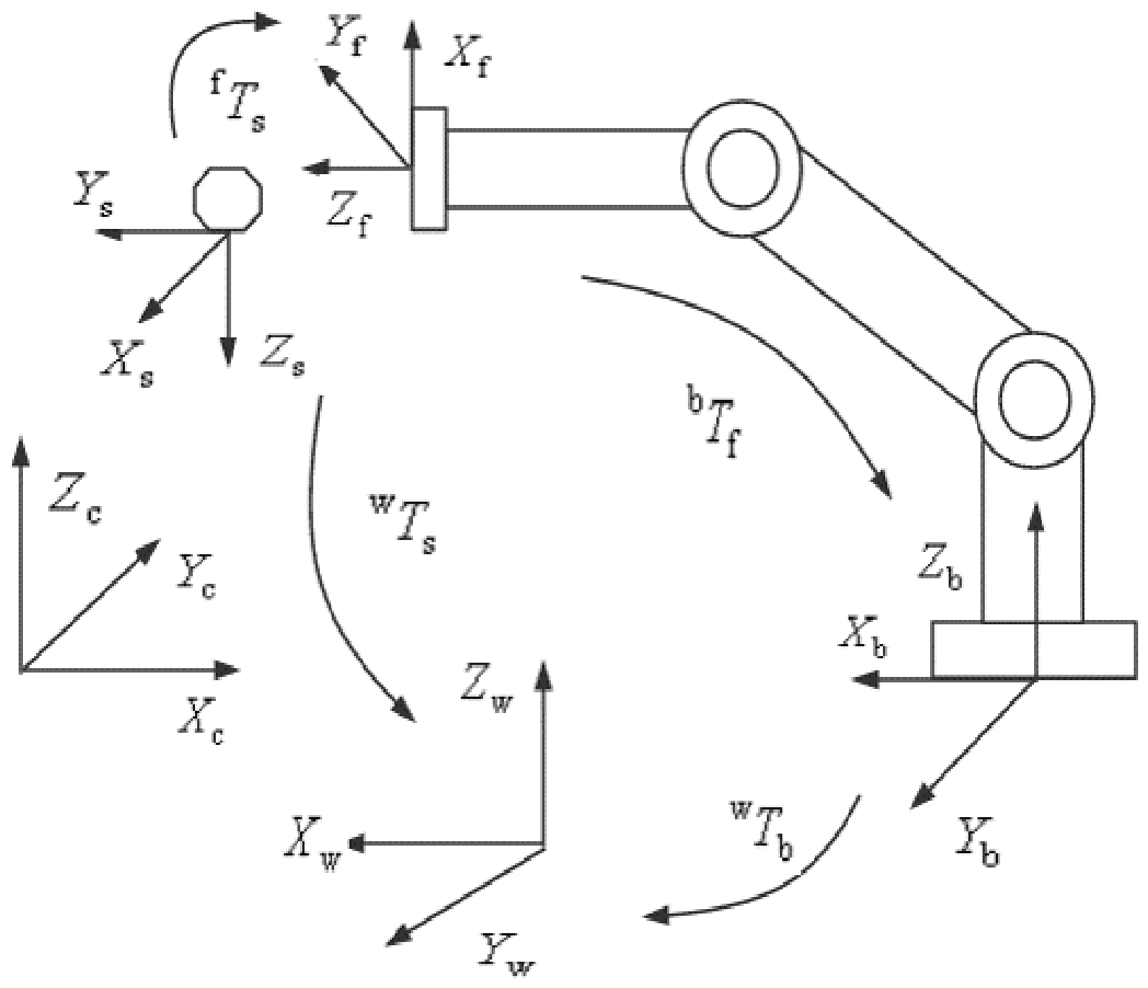
The joint variable is the angle of the rotation axis. For the industrial robot with 6 degrees of freedom (DOF), which affects the conversion relationship between the robot coordinate system and the flange coordinate system, the rotation angle can be read out from the robot controller, and then the robot base coordinate system and the sensor base coordinate system can be unified.
where i=1, 2, 3, 4, 5, 6, di is the offset distance from xn−1 to xn along the zn−1 direction, θi is the rotation angle from xn−1 to xn about the zn−1 direction, ai is the offset distance from zn−1 to zn along the xn direction, and αi is the rotation angle from zn−1 to zn about the xn direction.
5.1 Experiment set-up
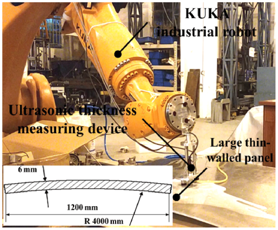
The Olympus M112-RM water immersion ultrasonic probe with 10 MHz center frequency was excited by the PAC AD-IPR-1210 ultrasonic signal card. The EX-422V eddy-current displacement sensor was used to measure distance and installed on the arm end of the KUKA KR 120 R2500 Pro industrial robot through a flange. The Tektronix MD0454C oscilloscope with an acquisition frequency of 2.5 GHz was used to display and collect the ultrasonic echo signal. Combined with the KUKA robot coordinate measurement system, the software system of industrial robot-assisted ultrasonic thickness measurement was compiled to realize the real-time measurement of panel thickness.
5.2 Thickness measurement
The coupling gap threshold calibration experiment was carried out for the 6061 aluminum alloy with a surface roughness of Ra 0.8. Before the measurement, use the dial indicator to make sure that the plate surface is level with the workbench. The ultrasonic probe moves from 0.1 to 4.5 mm along the +z axis with a step of 0.1 mm, and the amplitude of the ultrasonic echo signal corresponding to each coupling gap was calculated.
As shown in Fig. 6, the relative amplitude of the ultrasonic echo signal is large when the coupling gap is 0.7 to 1.5 mm, so the range was used as the threshold of coupling state discrimination. After that, in order to verify the effectiveness of the proposed method, a robot-assisted ultrasonic contactless scanning thickness measurement experiment was carried out on the aluminum alloy arc-shaped panel with a roughness of Ra 0.8.
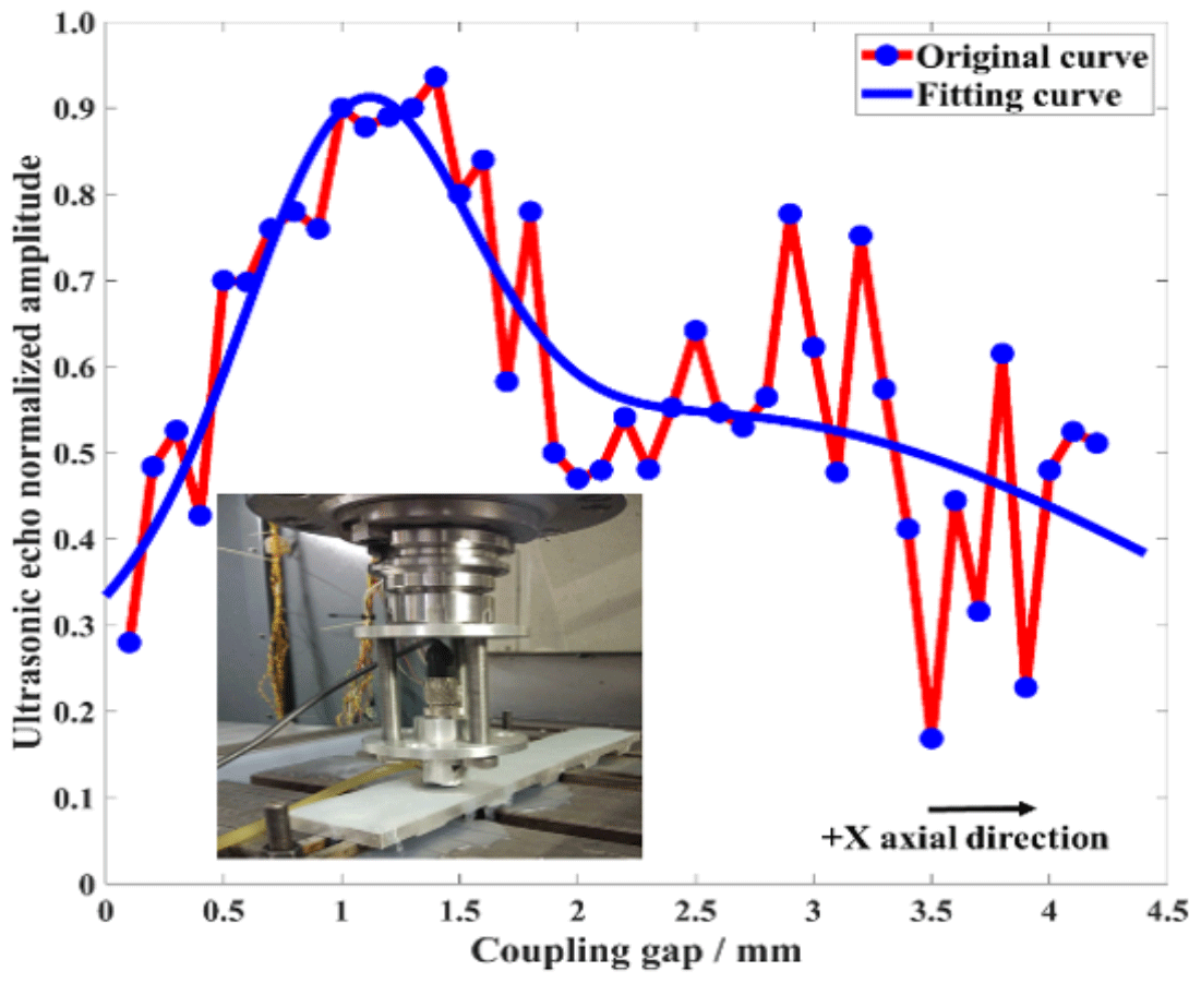
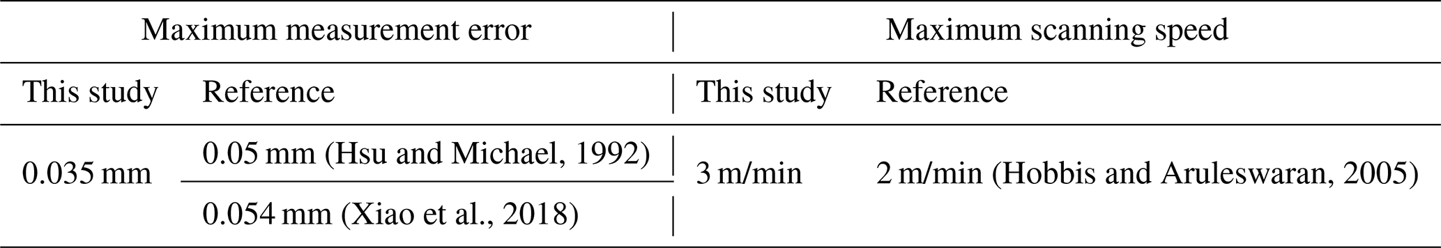
Table 1Comparison of the accuracy and efficiency of ultrasonic wall thickness measurement.
The wall thickness and propagation time at five measuring points on the tested panel were measured, and the propagation speed of the ultrasonic wave in the tested panel under the experimental environment is 6322.8 m/s. As shown in Fig. 7, the robot moves the ultrasonic thickness measurement device to the top of the measurement starting point, and the coupling gap is 1 mm. The total detection area in this experiment is 800 mm × 600 mm. The sampling period of measuring point coordinates, ultrasonic thickness measurement and eddy-current distance measurement is 100 ms; the threshold range of the coupling gap is 0.5 to 1.5 mm in the software. The scanning measurement speed ranges from 1.5 to 3 m/min. The emulsified cutting fluid with a volume concentration of 10 % was used as the coupling agent, and the flow rate was adjusted to 50 mL/s. The robot arm was controlled by the KRL program to carry out contactless scanning thickness measurement along the surface generatrix of the panel to be measured. The measurement process took about 10.5 min to measure 6300 points using the proposed method. The error compared with the standard ultrasonic thickness gauge is shown in Fig. 8. However, it took about 5 h to measure the equal amounts of points with the traditional ultrasonic thickness gauge. Thus, for the same work piece, the proposed automatic ultrasonic thickness measurement is much more efficient.
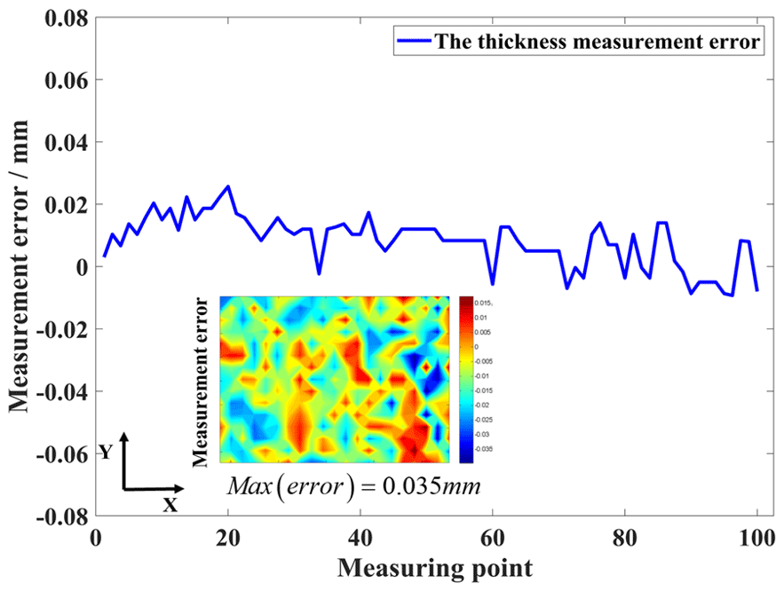
The maximum thickness measurement error is 0.035 mm, which shows that the robot-assisted ultrasonic contactless scanning thickness measurement can be realized by adjusting the coupling gap adaptively. As shown in Table 1, the accuracy and efficiency of ultrasonic wall thickness measurement are obviously improved compared with the previous studies. The proposed method is of positive significance to ensure the accuracy and efficiency of thickness measurement of large thin-walled parts.
This paper presents an industrial robot-aided ultrasonic thickness measurement system to meet the needs of precise and efficient wall thickness measurement of large thin-walled parts. The hardware platform of the system is established with the designed reliable and contactless ultrasonic thickness measurement device integrated into the executive end of the industrial robot. Based on the communication system architecture, the high-speed and stable communication relationship between the upper computer, robot motion controller, and ultrasonic thickness measurement unit is constructed using the TCP and UDP communication protocols, forming the ultrasonic automatic scanning thickness control system based on a robot platform. The adjustment determination unit model and execution methods utilizing eddy-current sensors are proposed to ensure the coupling gap between the ultrasonic scanning thickness measurement and the part. Finally, the industrial robot-based system of the ultrasonic thickness scanning measurement has been successfully built and tested. The experimental measurement process took about 10.5 min and obtained the thickness data of 6300 points. The maximum thickness measurement error is 0.035 mm, which showed that the method proposed in this paper has a positive significance for improving the accuracy and efficiency of thickness measurement.
The successful application of the proposed industrial robot-based thickness measurement system in the laboratory lays a foundation for automatic machining quality inspection of large-scale aerospace equipment, such as aircraft skin, liquid rocket engine nozzle and rocket fuel tank. Thus, how to apply this technique to improve the on-site measurement efficiency needs further development.
All datasets used in the paper can be requested from the corresponding author.
All work related to this paper has been accomplished by all the authors' efforts. HL, ML and YW conceived and designed the experiments; BL, ML, PL, and TL performed the experiments; TL analyzed the data; HL and ML wrote the paper.
The authors declare that they have no conflict of interest.
This article is part of the special issue “Robotics and advanced manufacturing”. It is not associated with a conference.
The authors acknowledge the financial supported from National Science and Technology Major Project of China, the National Natural Science Foundation of China, the Fundamental Research Funds for the Central Universities and the Changjiang Scholar Program of Chinese Ministry of Education.
This work has been supported by the National Science and Technology Major Project of China (grant no. 2019ZX04022001), the National Natural Science Foundation of China (grant no. 52003034), the Fundamental Research Funds for the Central Universities (grant nos. DUT2019TA01 and DUT20RC(3)007) and the Changjiang Scholar Program of the Chinese Ministry of Education (grant no. T2017030).
This paper was edited by Bo Li and reviewed by Xin Dong, Xiaobo Chen, and two anonymous referees.
Alatorre, D., Nasser, B., Rabani, A., Nagy-Sochacki, A., Dong, X., Axinte, D., and Kell, J.: Teleoperated, in situ repair of an aeroengine: Overcoming the internet latency hurdle, IEEE Robot Autom. Mag., 26, 10–20, https://doi.org/10.1109/MRA.2018.2881977, 2018.
Burghardt, A., Kurc, K., Szybicki, D., Muszyńska, M., and Szczęch, T.: Robot-operated inspection of aircraft engine turbinerotor guide vane segment geometry, Teh. Vjesn., 24, 345–348, https://doi.org/10.17559/TV-20160820141242, 2017.
Cai, S., Ma, Z., Skibniewski, M. J., and Bao, S.: Construction automation and robotics for high-rise buildings over the past decades: A comprehensive review, Adv. Eng. Inform., 42, 100989, https://doi.org/10.1016/j.aei.2019.100989, 2019.
Dong, X., Palmer, D., Axinte, D., and Kell, J.: In-situ repair/maintenance with a continuum robotic machine tool in confined space, J. Manuf. Process., 38, 313–318, https://doi.org/10.1016/j.jmapro.2019.01.024, 2019.
Enjikalayil Abdulkader, R., Veerajagadheswar, P., Htet Lin, N., Kumaran, S., Vishaal, S. R., and Mohan, R. E.: Sparrow: A Magnetic Climbing Robot for Autonomous Thickness Measurement in Ship Hull Maintenance, J. Mar. Sci. Eng., 8, 469, https://doi.org/10.3390/jmse8060469, 2020.
Han, Z. R., Fan, Z. J., Xiao, Y., and Jia, Z.: A research on thickness distribution of oblique cone in dieless shear spinning, Int. J. Adv. Manuf. Technol., 90, 2901–2912, https://doi.org/10.1007/s00170-016-9565-5, 2016.
Higuchi, K., Takeuchi, S., Sato, E., Naruo, Y., Inatani, Y., Namiki, F., Tanaka, K., and Watabe, Y.: Development and flight test of metal-lined CFRP cryogenic tank for reusable rocket, Acta Astronaut., 57, 432–437, https://doi.org/10.1016/j.actaastro.2005.03.059, 2005.
Hobbis, A. and Aruleswaran, A.: Non-contact thickness gauging of aluminium strip using EMAT technology, Nondestructive Test. Eva., 20, 211–220, https://doi.org/10.1080/10589750500491558, 2005.
Hsu, D. K. and Michael, S. H.: Simultaneous ultrasonic velocity and sample thickness measurement and application in composites, J. Acoust. Soc. Am., 92, 669–675, https://doi.org/10.1121/1.405279, 1992.
Hsu, D. K., Ayres, A. M., Meng, G., and Ma, G.: Simultaneous determination of ultrasonic velocity, plate thickness and wedge angle using one-sided contact measurements, NDT & E Int., 27, 75–82, https://doi.org/10.1016/0963-8695(94)90313-1, 1994.
Huang, N., Yin, C., Liang, L., Hu, J., and Wu, S.: Error compensation for machining of large thin-walled part with sculptured surface based on on-machine measurement, Int. J. Adv. Manuf. Technol., 96, 4345–4352, https://doi.org/10.1007/s00170-018-1897-x, 2018.
Huang, Y., Tang, C. Y., Zhang, M. X., Wang, Y. J., and Chen, Y. S.: Testing of a CNC control zbrasive belt grinding machine based on ultrasonic thick measure for nuclear zirconium alloy, Advanced Materials Research. Trans Tech Publications Ltd, 565, 70–75, https://doi.org/10.4028/www.scientific.net/AMR, 2012.
Kolluru, K., Axinte, D., and Becker, A.: A solution for minimising vibrations in milling of thin walled casings by applying dampers to workpiece surface, CIRP Ann.-Manuf. Techn., 62, 415–418, https://doi.org/10.1016/j.cirp.2013.03.136, 2013.
Kozlov, V., Samokrutov, A., and Shevaldykin, V.: Thickness measurements and flaw detection in concrete using ultrasonic echo method, Nondestruct. Test. Eva., 13, 73–84, https://doi.org/10.1080/02780899708953020, 1997.
Li, F. C., Chen, W. L., Li, H., and Zhang, R.: An ultrasonic transmission thickness measurement system for study of water rivulets characteristics of stay cables suffering from wind-rain-induced vibration, Sensor Actuat. A-Phys., 159, 12–23, https://doi.org/10.1016/j.sna.2010.01.036, 2010.
Lian, M., Liu, H., Zhang, T., Bo, Q., Li, T., and Wang, Y.: Ultrasonic on-machine scanning for thickness measurement of thin-walled parts: modeling and experiments, Int. J. Adv. Manuf. Technol., 104, 2061–2072, https://doi.org/10.1007/s00170-019-04021-5, 2019.
Liu, H., Wang, Y., Jia, Z., and Guo, D.: Integration strategy of on-machine measurement (OMM) and numerical control (NC) machining for the large thin-walled parts with surface correlative constraint, Int. J. Adv. Manuf. Technol., 80, 1721–1731, https://doi.org/10.1007/s00170-015-7046-x, 2015.
Pfeifer, T. and Benz, M.: Ultrasonic on-machine measurement for internal topographies, Int. J. Prod. Res., 40, 3821–3834, https://doi.org/10.1080/00207540210133525, 2002.
Pfeifer, T., Benz, M., Engelmann, B., and Hafner, P.: High precision ultrasonic on-machine measurement, Measurement, 39, 407–414, https://doi.org/10.1016/j.measurement.2005.11.026, 2005.
Wang, M., Palmer, D., Dong, X., Alatorre, D., Axinte, D., and Norton, A.: Design and development of a slender dual-structure continuum robot for in-situ aeroengine repair, 2018 IEEE/RSJ International Conference on Intelligent Robots and Systems (IROS), 5648–5653, https://doi.org/10.1109/IROS.2018.8594142, 2018.
Xiao, J., Zhao, S. L., Guo, H., Huang, T., and Lin, B.: Research on the collaborative machining method for dual-robot mirror milling, Int. J. Adv. Manuf. Technol., 105, 4071–4084, https://doi.org/10.1007/s00170-018-2367-1, 2019.
Xiao, X., Gao, B., Tian, G., Zhang, C., and Chen, S.: Novel ultrasound system with intelligent compensation for high precision measurement of thin wall tube, IEEE Sens. J., 18, 6633–6643, https://doi.org/10.1109/JSEN.2018.2826547, 2018.
- Abstract
- Introduction
- System hardware configuration
- Communication scheme
- Adaptive adjustment of the coupling gap
- Ultrasonic measurement of thicknesses of typical thin-walled parts
- Conclusions
- Data availability
- Author contributions
- Competing interests
- Special issue statement
- Acknowledgements
- Financial support
- Review statement
- References