the Creative Commons Attribution 4.0 License.
the Creative Commons Attribution 4.0 License.
 | 07 Apr 2021
Review article: Research on coupled vibration of multi-engine multi-gearbox marine gearing
Jingyi Gong
Geng Liu
Lan Liu
Long Yang
The type and working principle of multi-engine multi-gearbox gearing are introduced. The global dynamic modeling method, based on the generalized finite element theory, and the layered dynamic modeling method, based on the idea of whole first and then partial are proposed, and the dynamic models of three operation modes in the four engines with two shafts are established. The effects of coupling, rotation speed, configuration and power loss on the dynamic response of the system are studied by using the dynamic model. The research results show that the coupling vibration of multi-engine multi-gearbox gearing is obvious at low speed, and the coupling vibration weakens with the increase in speed. Reducing the coupling stiffness can weaken the coupling vibration of the system. The symmetrical structure of the transmission system has the same dynamic response at the symmetrical position. Meshing friction has little effect on the dynamic response of the system. The more power flowing through the cross-connect gearbox, the greater the system power loss. This research provides theoretical support for the low-vibration design of multi-engine multi-gearbox marine gearing and has a positive significance for understanding the coupled vibration characteristics of complex gear systems.
- Article
(3306 KB) - Full-text XML
- BibTeX
- EndNote


In the development of the ship power system, to solve the contradiction between the requirement of high power when sailing at full speed and the requirement of good economy when cruising, the multi-engine multi-gearbox marine gearing is produced. A multi-engine multi-gearbox is generally composed of two or more engines, with one or more gearboxes, clutches, couplings and other transmission components, according to the demand of power input and output. Compared with a single-engine power system, a multi-engine multi-gearbox system has the characteristics of higher power density, higher fuel economy and longer reliability (Schlappi, 1982; Willis, 1983).
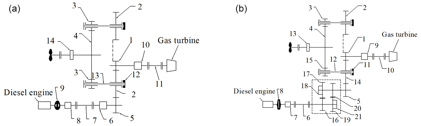
Figure 1Configurations of (a) CODOG (combined diesel or gas turbine) and (b) CODAG (combined diesel and gas turbine). Panel (a): 1 – I stage pinion of gas turbine; 2 – I stage wheel; 3 – II stage pinion; 4 – II stage wheel; 5 – I stage pinion of diesel engine; 6 and 10 – synchro-self-shifting clutch; 7 and 11 – universal joint; 8 – highly flexible coupling; 9 – hydraulic coupler; 12 – diaphragm coupling; 13 – torsion shaft; and 14 – main thrust plate. Panel (b): 1 – I stage pinion of gas turbine; 2 – I stage wheel; 3 – II stage pinion; 4 – II stage wheel; 5 – I stage pinion of diesel engine; 6 and 10 – universal joint; 7 – highly flexible coupling; 8 – hydraulic coupler; 9 – synchro-self-shifting clutch; 11 – diaphragm coupling; 12 – torsion shaft; 13 – main thrust plate; 14 and 15 – first speed ratio gear pair; 16 and 19 – clutch; and 17 and 18 – second speed ratio gear pair.
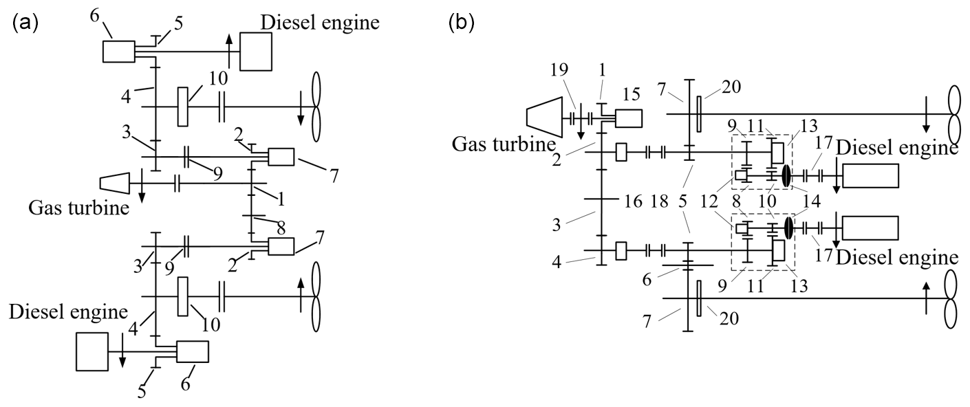
Figure 2Cross-connect gear (CCG) transmission system of three engines with two shafts of (a) CODOG and (b) CODAG. Panel (a): 1 – I stage pinion of gas turbine; 2 – I stage wheel; 3 – II stage pinion; 4 – II stage wheel; 5 – I stage pinion of diesel engine; 6 – controllable clutch; 7 – synchro-self-shifting clutch; 8 – idler gear; 9 – flexible coupling; and 10 – main thrust plate. Panel (b): 1 – I stage pinion of gas turbine; 2 and 4 – I stage wheel; 3 and 6 – idler gear; 5 – II stage pinion; 7 – II stage wheel; 8 – first speed ratio pinion; 9 – first speed ratio wheel; 10 – second speed ratio pinion; 11 – second speed ratio wheel; 12 and 13 – speed ratio clutch; 14 – hydraulic coupler; 15 – synchro-self-shifting clutch; 16 – countershaft clutch; 17 – diesel engine coupling; 18 and 19 – flexible coupling; and 20 – main thrust plate.
Although the gearing has the above advantages, the vibration response of the system will change when the gearboxes are connected by coupling. Wang et al. (1996, 1997) analyzed the vibration characteristics of the two engines with one gearbox system, and the calculated results of the dynamic model are close to the test ones. The research team at Northwestern Polytechnical University, Xi'an, China, studied the coupling vibration of different types of multi-engine multi-gearbox marine gearing (Zhao, 2018; Meng, 2019; Ma, 2020; Li, 2020). Coupling of gear systems mainly includes coupling of degrees of freedom, coupling of multi-stage gear pairs and coupling of supporting systems. Toridon and Gavin (1977) analyzed the coupled bending torsional vibration of a two-stage spur gear system. Kahraman (1994) established a three-dimensional vibration model of two-stage helical gears with full degrees of freedom of bending, torsion, axis and pendulum and studied the influence of idler gear teeth numbers and installation phase angle on the vibration characteristics of the system. For the coupling of multi-stage gear pairs, Raclot (1999) and Walha et al. (2009) established a two-stage gear system dynamic mode and found the phenomenon of a coupled vibration. Sun et al. (2014) studied the influence of excitation frequency on the coupled vibration of multi-stage planetary gears. Wei et al. (2017) summarized several vibration modes of multi-stage planetary gears. For the coupling of a supporting system, Vázquez et al. (2001) proposed a method, using a transfer function, to consider the flexible effect of gearbox support in dynamic analysis. Ren et al. (2017, 2018) established a fully coupled dynamic model of a single-stage gearbox, using the impedance synthesis method. Lu et al. (2020) used the static sub-structure method to couple the housing with the multi-stage gear rotor system.
As shown in the above analysis of the published research, there is some research on the coupling vibration of the multi-engine multi-gearbox gearing, and the introduction of its configuration and working principle is not sufficient. Therefore, it is necessary to summarize the configuration and working principle of multi-engine multi-gearbox gearing and study the coupling vibration characteristics of this kind of system. The rest of this paper is organized as follows: Sect. 2 introduces the configuration and working principle of two types of multi-engine multi-gearbox gearing. Section 3 proposes two coupled dynamic modeling methods based on the overall modeling idea and the layered modeling idea and establishes the dynamic model of the three operating modes in the four engines with two shafts system. Section 4 studies the influence of coupling, rotation speed, configuration and power loss on the dynamic response of the system based on the established model. Section 5 summarizes some conclusions based on the numerical analysis results and prospects for later research.
2.1 Combined power transmission system
There are mainly two types of combined power transmission systems used in cruisers and naval vessels. The first is the combination type of “or” systems such as CODOG (combined diesel or gas turbine) or COGOG (combined gas turbine or gas turbine). The second is the combination type of “and” systems called CODAG (combined diesel and gas turbine) or COGAG (combined gas and gas turbine). In the or propulsion systems, only one of the engines works at the same time, and they will change the working mode alternatively, according to the status of the ships in cruising or fast gears, whereas, in the and systems, the engines can be used individually or together to strengthen the propulsion power (Yu and Wang, 2009).

Figure 1a gives a configuration of CODOG for which a diesel engine and a gas turbine drive the propeller shaft respectively. When the ship is cruising, the diesel engine works, and the diesel engine power is transmitted to the propeller shaft through the gears 5–2–3–4. When the ship is accelerating, the hydraulic coupling 9 and SSS (synchro-self-shifting) clutch 6 are disconnected. Then, diesel engine stops working, and the power of the gas turbine is transmitted to the propeller shaft through the gears 1–2–3–4.
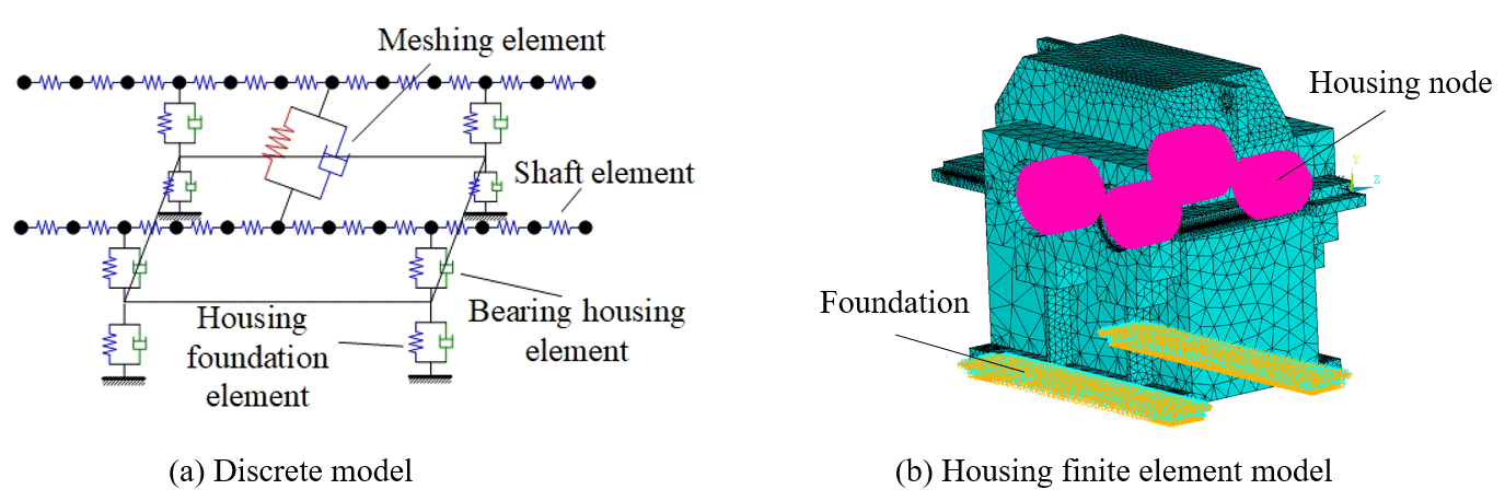


Figure 1b shows a configuration of CODAG, a diesel engine, and a gas turbine that drives the propeller shaft either separately or together. When the ship is cruising, the diesel engine works, and the gas turbine does not work. The diesel engine's output power is transmitted to the propeller shaft through the gears 14–15–2–3–4. When the power is required to be combined and output, the power of the diesel engine is transmitted to the stage I gear 2 through gears 17–18, and the power of the gas turbine is also transmitted to the stage I gear 2 through gear 1. The power of the two engines converges and is transmitted to the propeller shaft through the gears 3–4.
2.2 Combined power cross-connect gear transmission system
A combined power cross-connect gear (CCG) transmission system uses a cross-connect gear to connect port and starboard input power, which not only has the function of combined power transmission system but can also utilize one engine to drive two propeller shafts simultaneously, so that the high-power main runs at the optimal efficiency design point, and further improve fuel economy and reliability compared with a combined power transmission system (Yu and Wang, 2009).
Figure 2 shows a three engines with two shafts CCG transmission system. The shaft refers to the propeller shaft, which is shown in Fig. 2a as a CODOG CCG transmission system and in Fig. 2b as a CODAG CCG transmission system. When the ship is cruising, the two diesel engines transmit power to their respective propeller shafts through gears 5–4. When the ship is accelerating, the gas turbine power is transmitted to the two propeller shafts through the gears 1–2–3–4 and 1–8–2–3–4, respectively. The CODAG CCG transmission system has the following four operating modes: (1) the power of two diesel engines is transmitted to the respective propeller shafts through gears 8–9–5–7 and 8–9–5–6–7 during the cruise; (2) one diesel engine works during the economic cruise and is transmitted to the port and starboard propeller shafts through gears 8–9–5–7 and 8–9–5–2–3–4–5–6–7; (3) when the gas turbine is running alone, the gas turbine power is transmitted to the port and starboard propeller shafts through the gears 1–2–5–7 and 1–2–3–4–5–6–7; and (4) when combined power runs, the two diesel engines carry out the power transmission in the first operating mode, and the gas turbine carries out power transmission in the third mode. At this time, the ship obtains the maximum propulsion power and has the highest speed.
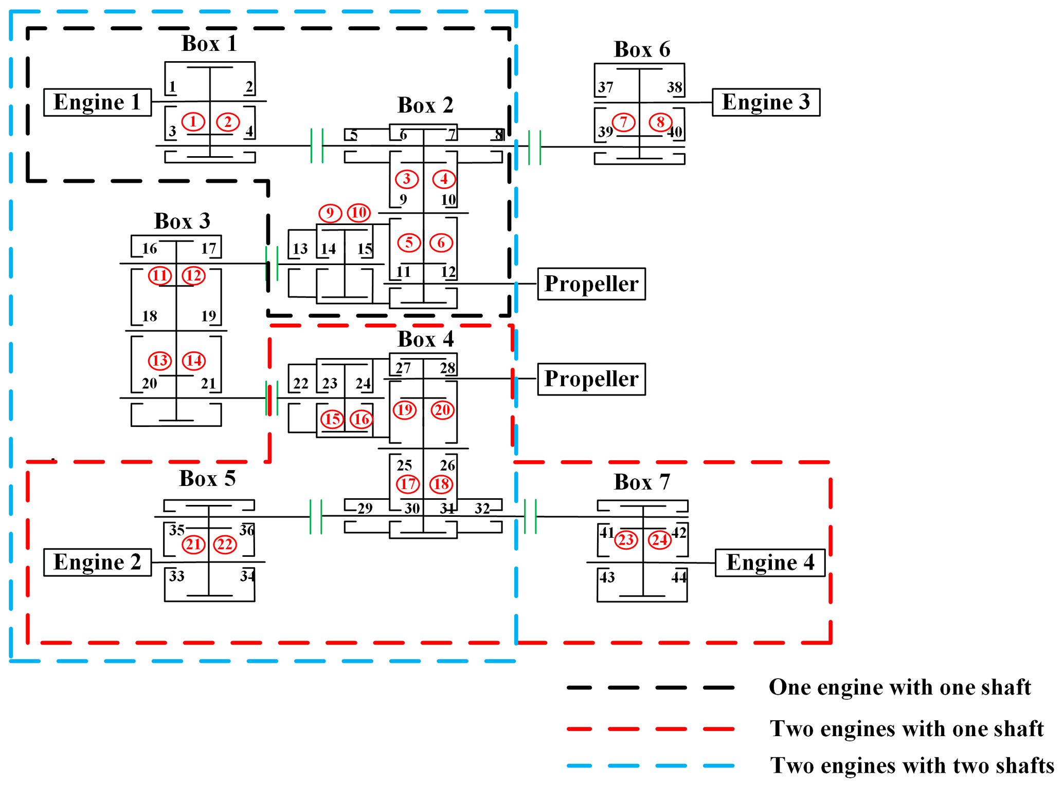
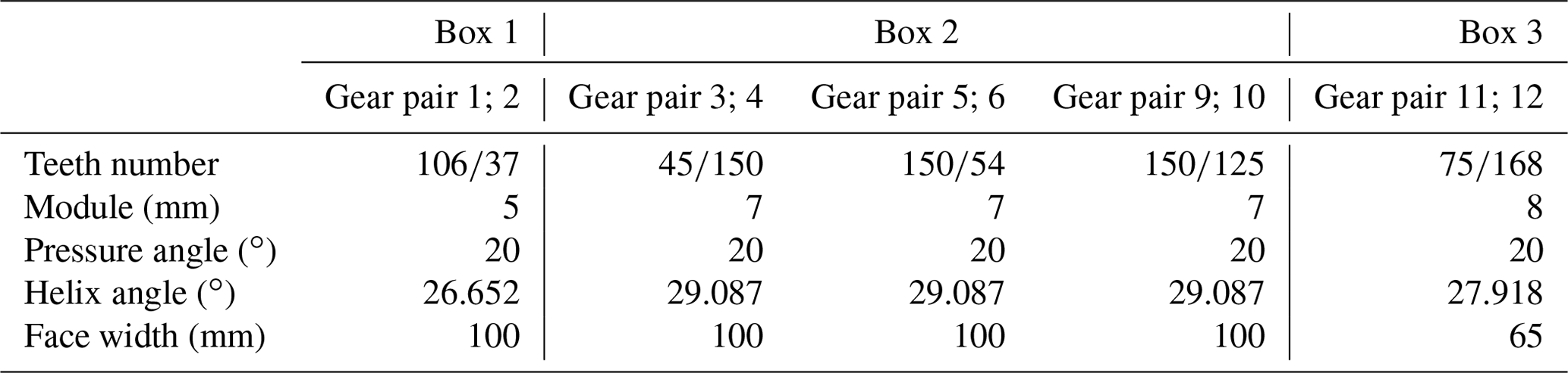
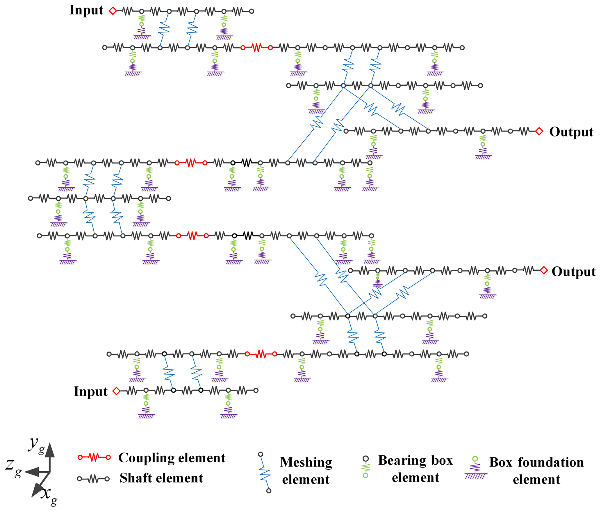
Figure 3 shows a four engines with two shafts system. Each gearbox in the system adopts a herringbone gear pair. The actual operation modes of the system include one engine with one shaft, two engines with one shaft, two engines with two shafts, etc. This section introduces two modeling methods to build this kind of multi-gearbox system and introduces the dynamic models of three operation forms according to these methods. The gear parameters in the system are shown in Table 1. Because of the symmetry of the system, the gear parameters of nos. 4–6 gearboxes are the same as those of their symmetrical gearboxes. The coupling stiffness, bearing stiffness and damping in the system are shown in Table 2.
3.1 Global coupling dynamic model
The generalized finite element method is used to establish the overall coupling dynamic model of the system. Taking a single-stage gearbox as an example, the gearbox is discretized into meshing element, shaft element, bearing housing element and housing foundation element, as shown in Fig. 4a. Each element is composed of gear nodes, shaft nodes, bearing nodes, box nodes, etc. Node division rules are introduced in the literature (Yuan et al., 2017). The mass and stiffness and damping of the housing foundation element are extracted from the finite element software by the static substructure method. As shown in Fig. 4b, the inner hole surface of the bearing seat is coupled to the central node by a rigid beam element. The displacement of the base is fully constrained. Then, the equivalent stiffness and mass matrix of the housing foundation element are extracted by the static substructure method. The mass, stiffness and damping matrix of the other element is obtained by force analysis. They are assembled according to the physical connection relationship to obtain the overall dynamic model of the system.
For the three operation modes of four engines with two shafts, the corresponding dynamic models are established based on the generalized finite element method, as shown in Figs. 5 and 6. The finite element method and analytical contact mechanics method are used to establish a quasi-static contact model of the gear pair, and the calculated time-varying mesh stiffness is used as the internal excitation of the dynamic model (Chang et al., 2015). Equation (1) is the matrix form of the differential equations of motion of these two models, and x is the generalized coordinate vector of the system, M is the system quality matrix, C is the system damping matrix, K(t) is the system time-varying stiffness matrix, and P0 is the external load vector. The matrix equations are parametric differential equations, which are solved by the Fourier series method.
Similar to the first two models, the dynamic model of two engines with two shafts is shown in Fig. 7. In the model, not only the time-varying meshing stiffness excitation but also the meshing friction excitation are considered. The meshing friction excitation includes the time-varying friction force and time-varying friction torque, and the friction excitation is obtained by calculating time-varying contact line length (Ma, 2020). The form of the differential equation of the system motion can be expressed as Eq. (2). Ff(t) is a time-varying friction excitation.

3.2 Layered coupled dynamic model
Aiming at the characteristics of the dynamic model established by the generalized finite element method, there are many nodes and degrees of freedom, and the solution efficiency is low when the model is complex. Therefore, another efficient modeling method is proposed, as shown in Fig. 8. This method adopts the modeling idea of whole first and then partial. First, a rigid–flexible coupling dynamic model of the overall multi-gearbox transmission system was established, and the boundary conditions at the coupling element were obtained. Then, a generalized finite element method was used to establish a dynamic model of the single gearbox, and the boundary conditions at the coupling were included. This method can obtain a dynamic model that considers the coupling effect of the overall system and has fewer degrees of freedom.
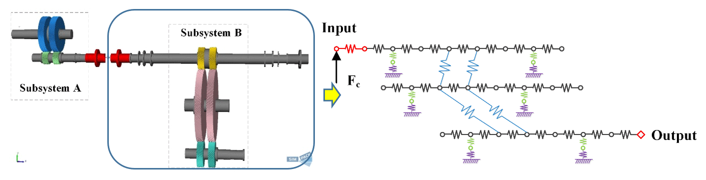
As shown in Fig. 9, there is a rigid–flexible coupling model of a one engine with one shaft transmission system. The half-coupling of the diaphragm coupling was treated, with a Timoshenko beam, as a flexible body, and the diaphragm group was simplified as a spring with stiffness and damping. The mass and moment of inertia of the coupling are ignored in the model. The meshing excitation in the model is calculated based on ISO (International Organization for Standardization) 6336. The bearing support stiffness is considered as being a spring element with a coupling term. The dynamic model of subsystem B is established by the generalized finite element method. The coupling wave force Fc is included in the dynamic model of subsystem B to obtain a dynamic model that considers the overall system coupling effect. The model has fewer nodes, and the solution is faster. The matrix form of the kinematic differential equation can be expressed as Eq. (3). The model considers gear manufacturing, coupling vibration misalignment and time-varying meshing stiffness. Fc(t) is the coupling wave force. e(t) is the gear manufacturing error.
Table 3Correspondence between influencing factors and research objects.
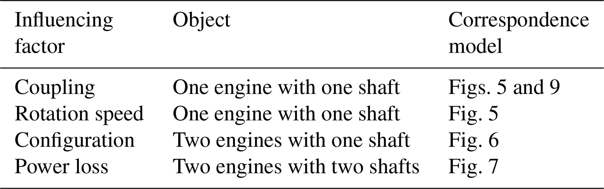

In this section, the model established in Sect. 3 is used to study the influence of coupling, rotation speed, configuration and power loss on the dynamic characteristics of the multi-gearbox system. The specific correspondence is shown in Table 3. The gear pair number and box number mentioned in this section are shown in Fig. 3.


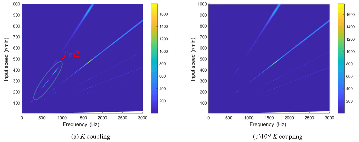
Figure 12Dynamic meshing force spectrum under different coupling stiffness. As an important transmission component in a multi-gearbox system, the coupling is worthy of study on the effect of its stiffness on the vibration response. Figure 12 shows the frequency spectrum of the meshing force of the no. 1 meshing element at the original coupling stiffness (K coupling) and 10−3 times the coupling stiffness (10−3 K coupling). It can be seen that the coupling vibration of the no. 1 meshing element at 230–450 rpm (revolutions per minute) on K coupling is strong, and the amplitude of fm2 is relatively large. At 10−3 K coupling, the corresponding amplitude of fm2 disappears. Therefore, reducing the stiffness of the coupling can weaken the coupling vibration of the system.

4.1 Effect of coupling
The effect of coupling is studied by using the dynamic model of one engine with one shaft established in Fig. 5 in this paper. It can be seen from Fig. 10 that the fluctuation of meshing force before coupling of a gearbox gear pair in the system is 950 N. After connecting another gearbox through a coupling, the fluctuation of the meshing force after coupling is 2736 N, and the fluctuation of meshing force increases 2.88 times. Observing the meshing force spectrum after coupling, it is found that the frequency fm2 corresponding to the maximum amplitude is not its own meshing frequency but the meshing frequency of another gearbox. So, the gearboxes in the transmission system are connected by the coupling to generate the coupled vibration. The coupled vibration between gearboxes has a significant impact on the dynamic response of the system. This is because the vibration of the gearboxes is transmitted to each other through the coupling, which enhances the dynamic response of the system, so the dynamic meshing force fluctuation increases after coupling. As shown in Fig. 11, it can be seen from the frequency spectrum that the increase in the amount of meshing force fluctuation is mainly caused by the vibration transmission of other gearboxes. Because the multi-gearbox system has a coupled vibration effect, the dynamic response should be analyzed from the perspective of the overall system in the research.
For one engine with one shaft, the layered coupling dynamic model shown in Fig. 9 is used for research. As shown in Fig. 13, the shaft frequency component appears in the meshing force spectrum of the no. 3 meshing element. At 240 rpm (revolutions per minute), the corresponding amplitude of the shaft frequency is very small, and at 1040 rpm, the shaft frequency is the main frequency component in the spectrum. This is because the vibration misalignment caused by different the vibration intensity between gearboxes is considered in the layered coupling dynamic model, which leads to misalignment of the coupling and then produces shaft frequency excitation in the system. For a multi-gearbox system, the shaft frequency excitation caused by vibration misalignment has little influence on the vibration response of the system at low speed, which can be ignored but should be considered at high speed.
4.2 Effect of rotation speed
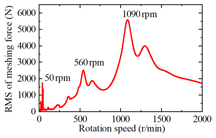
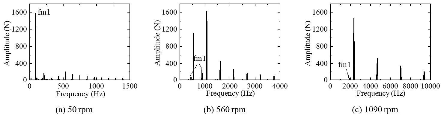
The rotational speed is directly related to the excitation frequency of the system in the gear system. We use the one engine with one shaft dynamic model, shown in Fig. 5, to study the effect of box 1 on the coupled vibration of box 2 with speed changes. Figure 14 shows the root mean square curve of the dynamic meshing force of the no. 1 meshing element in box 1. The meshing element resonates at three speeds of 50, 560 and 1090 rpm, respectively. The vibration response of the no. 3 meshing element in box 2 is studied under these three speeds. Figure 15 shows the meshing force spectrum of the no. 3 meshing element. It is observed that the amplitude of box 1 meshing frequency fm1 gradually decreases as the speed increases, and the coupling effect of the system decreases. This is because the excitation frequency of the system increases with the increase in speed, and the vibration transmission decreases with the increase in the excitation frequency. Even if the main resonance occurs when the no. 1 meshing element is at 1090 rpm, it has little effect on the no. 3 meshing element. For a multi-gearbox system, as the speed increases, the coupled vibration of the system weakens. The coupled vibration of the system mainly occurs at low speeds.
4.3 Effect of configuration
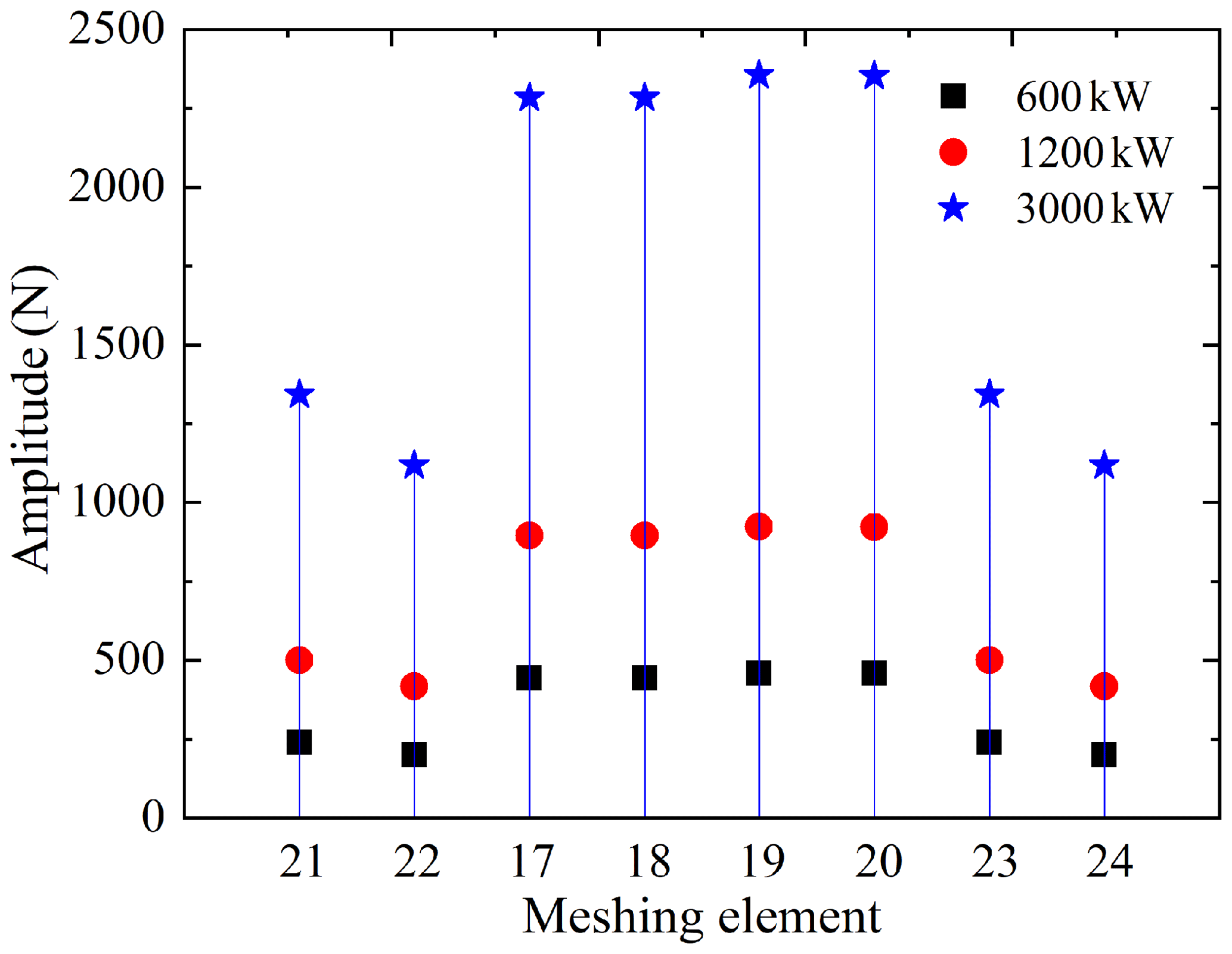
The operating mode of two engines with one shaft is when the ship is sailing at full speed. Box 3 in Fig. 3 is not working, and power is transmitted by two completely symmetrical engines with one shaft. During operation, the input power and speed of the two engines are required to be the same. The two engines with one shaft dynamic model, established in Fig. 6, is used to study the influence of the symmetrical configuration on the system's dynamic response. The input power of the two main engines is set to 600, 1200 and 3000 kW, and the input speed is 1500 rpm. As shown in Fig. 16, the meshing force fluctuations of the nos. 21 and 23 meshing elements at the symmetrical position are the same under the three working conditions, which are 238, 500 and 1343 N, respectively. The meshing force fluctuations of the meshing elements at other symmetrical positions are also the same. Therefore, the dynamic response of the symmetrical structure of the multi-gearbox system is also symmetrical, and the amount of the meshing force fluctuation of the system increases with the increase in input power.
4.4 Effect of power loss
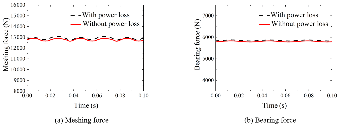
The influence of the power distribution on the power loss of the system is studied by using the two engines with two shafts dynamic model, in Fig. 7, which considers the meshing friction. When the input power of each engine is different, the cross-connect gearbox box 3 will distribute the power. The speed of box 1 and box 5 is 1500 rpm, the input power is 1000 and 800 kW, respectively, the output power of the two propeller shafts is 900 kW and the distributed power of the cross-connect gearbox box 3 is 100 kW. The frictional excitation of each gear pair in the system is calculated by the time-varying contact line method, and the kinematics equation is solved to obtain the dynamic response of the system. As shown in Fig. 17, after considering the power loss, the average value and fluctuation of the gear pair meshing force and bearing force did not change significantly, indicating that the power loss caused by meshing friction has little effect on the dynamic response of the system.
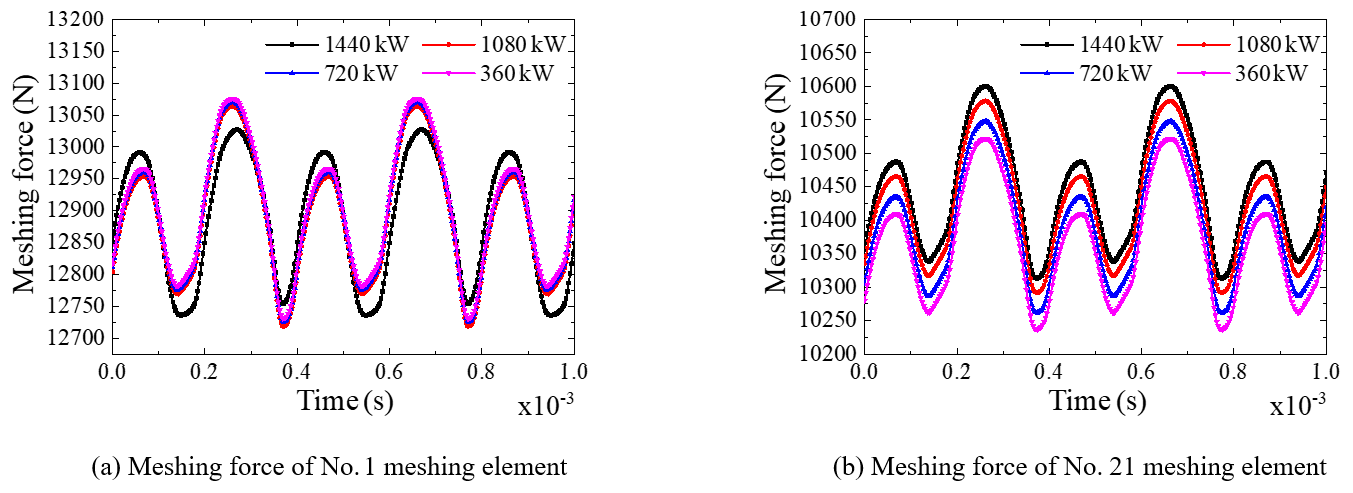
The power loss is related to the power transmission path and power allocation. It is assumed that the total output power of the two engines with two shafts is 1800 kW, and the input speed of two engines is 1500 rpm. Setting the output power ratio of two propeller shafts as 1:9, 2:8, 3:7 and 4:6, the power flowing through the cross-connect gearbox (CCG) is 1440, 1080, 720 and 360 kW. The greater the mean value of the meshing force of the gear pairs of the two input gearboxes, box 1 and box 5, and the greater the input power, the greater the system power loss. Combining Fig. 18 and Table 4, it can be seen that the average meshing force of the no. 1 meshing element in box 1 is unchanged, and the input power is unchanged. The mean meshing force of the no. 21 meshing element in box 5 increases with the increase of the power flowing through the CCG, so the total input power of the system increases. This is because, when the power transmission path is unchanged, the greater the transmitted power, the greater the power loss, and the more input power is required. Therefore, the more power that the multi-gearbox system flows through the CCG, the greater the system power loss. In the design, it is advisable to try to avoid a high power distribution ratio.
This paper reviews the typical configurations of multi-engine multi-gearbox of marine gear transmission systems. The influences of the models and key factors on the coupled vibration characteristics of the systems are introduced and analyzed. The results show that the coupling influences of multiple excitations of the systems on the dynamic responses should draw more attention in the process of low noise design. The main findings are summarized as follows: (1) at low speeds, the coupling vibration of the system is obvious. Reducing the stiffness of the coupling can reduce the vibration transmission between gearboxes. The shaft frequency excitation caused by the vibration dislocation between the boxes plays a major role when the system is high speed. (2) As the speed increases, the coupled vibration of the system gradually weakens. (3) The vibration response of the system with a symmetrical configuration is the same at the symmetrical position. (4) The meshing friction has little effect on the dynamic response of the system. When considering the system power loss of the meshing friction, the greater the power flowing through the CCG, the greater the system power loss.
The prospects of the research on the multi-engine multi-gearbox system are as follows: (1) it is imperative to establish more effective models for the analysis of multi-engine multi-gearbox transmission systems. (2) There are a few kinds of excitations in multi-engine multi-gearbox marine gear systems. It is of great significance to study the coupling vibration characteristics under multiple excitations and to explore the vibration transfer laws along with the longitudinal and axial directions for vibration and noise reduction of the systems. (3) Marine gear transmission is developing towards higher speed, higher power density and longer lifespan and reliability. The robust design methods of the transmission systems under different working conditions and transmission forms are necessary to keep the systems at a relatively low vibration level.
Data are available from the authors upon request.
JG and GL discussed the idea. JG wrote the paper. GL reviewed the paper. LL participated in the establishment of the dynamic model. LY collected and provided the model data. All authors have read and agreed on the published version of the paper.
The authors declare that they have no conflict of interest.
This article is part of the special issue “Robotics and advanced manufacturing”. It is not associated with a conference.
The author thanks the anonymous reviewers for their valuable comments and the editors for their language and typesetting services.
This research has been supported by the National Key R&D Program of China (grant no. 2018YFB2001501) and the Key Program of National Natural Science Foundation of China (grant no. 51535009).
This paper was edited by Peng Li and reviewed by four anonymous referees.
Chang, L. H., Liu, G., and Wu, L. Y.: A robust model for determining the mesh stiffness of cylindrical gears, Mech. Mach. Theory, 87, 93–114, https://doi.org/10.1016/j.mechmachtheory.2014.11.019, 2015.
Kahraman, A.: Dynamic analysis of a Multi-Mesh helical gear train, J. Mech. Des., 116, 706–712, https://doi.org/10.1115/1.2919440, 1994.
Li, X. F.: Researches on Multi-gearbox Dynamics Analysis method and dynamic characteristic, Master thesis, Northwestern Polytechnical University, Xi'an, 9–19, 2020.
Lu, W. J., Zhang, Y. M., and Zhou, Y.: Research on dynamic behavior of multistage gears-bearings and box coupling system, Measurement, 150, 107096, https://doi.org/10.1016/j.measurement.2019.107096, 2020.
Ma, D.: Research on Dynamic Characteristics of Multi-Input Multi-Output Gear Transmission System, Master thesis, Northwestern Polytechnical University, Xi'an, 6–26, 2020.
Meng, C. L.: Research on Dynamic Characteristics of Marine Combined Power Transmission, Master thesis, Northwestern Polytechnical University, Xi'an, 9–25, 2019.
Raclot, J. P.: Simulation of the Dynamic Behaviour of Single and Multi-Stage Geared Systems with Shape Deviations and Mounting Errors by Using a Spectral Method, J. Sound Vibr., 220, 861–903, https://doi.org/10.1016/10.1006/jsvi.1998.1988, 1999.
Ren, Y. F., Chang, S., and Liu, G.: Impedance Synthesis Based Vibration Analysis of Geared Transmission System, Shock Vib., 2017, 1–14, https://doi.org/10.1155/2017/4846532, 2017.
Ren, Y. F., Chang, S., and Liu, G.: Vibratory Power Flow Analysis of a Gear-Housing-Foundation Coupled System, Shock Vib., 2018, 1–13, https://doi.org/10.1155/2018/5974759, 2018.
Schlappi, H. C.: An Innovative Energy Saving Propulsion System for Naval Ships, Nav. Eng. J., 94, 200–213, https://doi.org/10.1111/j.1559-3584.1982.tb02438.x, 1982.
Sun, W., Ding, X., Wei, J., Hu, X., and Wang, Q.: An analyzing method of coupled modes in multi-stage planetary gear system, Int. J. Precis. Eng. Manuf., 15, 2357–2366, https://doi.org/10.1007/s12541-014-0601-9, 2014.
Toridon, G. V. and Gauvin, R.: Dynamic stability of a two-stage gear train under the influence of variable meshing stiffness, Trans. ASME Ser. B., 99, 785–791, https://doi.org/10.1115/1.3439314, 1977.
Vázquez, J. A., Barrett, L. E., and Flack, R. D.: A Flexible Rotor on Flexible Bearing Supports: Stability and Unbalance Response, J. Vib. Acoust.-Trans. ASME, 123, 137–144, https://doi.org/10.1115/1.1355244, 2001.
Walha, L., Fakhfakh, T., and Haddar, M.: Nonlinear dynamics of a two-stage gear system with mesh stiffness fluctuation, bearing flexibility and backlash, Mech. Mach. Theory., 44, 1058–1069, https://doi.org/10.1016/j.mechmachtheory.2008.05.008, 2009.
Wang, G. X.: Dynamic Simulation of a Gearbox of Testing Combined Diesel and Gas Turbine Naval Power Plant, J. Harbin Eng. Univ., 17, 31–37, 1996.
Wang, G. X. and Li, S. Y.: Dynamic Simulation and Experimental Study of a Gearbox of Testing Conbined Diesel or Gas Turbine Power Plant, Shipbuilding of China, 000, 96–105, https://doi.org/10.1007/BF02029074, 1997.
Wei, J., Zhang, A., Qin, D., and Hou, S.: Analytical coupling characterization of multi-stage planetary gear free vibration considering flexible structure, J. Vibroeng., 19, 3994–4008, https://doi.org/10.21595/jve.2017.17767, 2017.
Willis, J. A.: Mechanical Cross-connect Gear Transmission for U.S. Navy Destroyrers, Nav. Eng. J., 95, 214–226, https://doi.org/10.1111/j.1559-3584.1983.tb01639.x, 1983.
Yu, F. and Wang, M. W.: Machining and Design of Marine gear reduction device, National Defense Industry Press, BeiJing, 66–71, 2009.
Yuan, B., Chang, S., and Liu, G.: Optimization of bias modification and dynamic behavior analysis of helical gear system, Adv. Mech. Eng., 9, 168781401773325, https://doi.org/10.1177/1687814017733252, 2017.
Zhao, Y.: Research on Vibration Characteristics of Marine Combined Power Transmission, Master thesis, Northwestern Polytechnical University, Xi'an, 7–27, 2018.
Zhao, Y. and Tong, R. T.: Research of the Coupled Vibration Characteristic of Double Gearbox Transmission System, J. Mechan. Trans., 42, 1–6, https://doi.org/10.16578/j.issn.1004.2539.2018.09.001, 2018.
- Abstract
- Introduction
- Main configurations of multi-engine multi-gearbox marine gearing
- Dynamic models of multi-engine multi-gearbox transmission systems
- Coupled vibration characteristics of multi-engine multi-gearbox transmission systems
- Conclusions and prospect
- Data availability
- Author contributions
- Competing interests
- Special issue statement
- Acknowledgements
- Financial support
- Review statement
- References