the Creative Commons Attribution 4.0 License.
the Creative Commons Attribution 4.0 License.
 | 01 Apr 2021
Rattle dynamics of noncircular face gear under multifrequency parametric excitation
Zhenzhen Lv
Guohao Zhao
A noncircular face gear (NFG) conjugated with a pinion is a new type of face gear which can transmit variable velocity ratio and in which two time-varying excitations exist, namely the meshing stiffness excitation and instantaneous center excitation. Considering the tooth backlash, static transmission error and multifrequency parametric excitation, a nonlinear dynamic model of the NFG pair is presented. Based on the harmonic balance method and discrete Fourier transformation, a semi-analytic approach for the nonlinear dynamic model is given to analyze the dynamic behaviors of the NFG. Results demonstrate that, with increase in the eccentric ratio, input velocity and error amplitude, the NFG will undergo a non-rattle, unilateral rattle and bilateral rattle state in succession, and a jump phenomenon will appear in the dynamic responses when the rattle state of the gears is transformed from unilateral rattle to bilateral rattle.
- Article
(14593 KB) - Full-text XML
- BibTeX
- EndNote


Noncircular face gear (NFG) drive is a new type of variable transmission ratio mechanism with the advantages of light weight, high interchangeability and convenient installation (Liu et al., 2017). It is widely applicable in agricultural machinery, robots, automobiles, automatic machines and so on. Generally, irregular rattle vibration often appears in a gear system in light load or no load conditions, which not only has negative effects on the dynamic characteristics of the gears but also causes an unpleasant rattling noise. Due to the variable transmission ratio, the rattle vibration occurs in the noncircular gear transmission system more easily, which is a key problem to be solved urgently for noncircular face gears.
The rattle vibration of gears is a strongly nonlinear dynamic behavior caused by the tooth backlash. The vibration shock model, based on the lumped parameter method, is generally applied in theoretical research. The gear pair is a basic element in gear systems. Correspondingly, the torsional vibration model is the fundamental form of the dynamic model of gears. Comparin et al. presented a single degree of freedom nonlinear model for the purely torsional vibration and found three rattle states of gears (Comparin and Singh, 1989). By considering the stiffness of the bearings and shafts, a coupled translation–rotation vibration model is proposed by Kahraman and Singh (1991) to investigate the amplitude frequency features and chaotic vibration. On the basis of the coupled dynamic model of a single stage gear, Zhang et al. (2003a, b) introduced an impact equation to describe the sudden change in the dynamic behaviors of the gear when tooth impact occurs and indicated the influences of the speed fluctuation and unbalanced mass on the rattle vibration. For helical gears, a lateral–torsional–axial coupled nonlinear dynamic model was proposed to discuss the effects of system parameters on the vibration and the bifurcation behaviors by Wei et al. (2013).
Based on the dynamics of a single-stage gear drive, the dynamic characteristics of planetary gear systems were deeply studied. In the works of Al-shyyab and Kahraman (2007), a semi-analytical approach, based on the harmonic balance method, discrete Fourier transformation and Newton's method, is developed to solve the nonlinear torsional vibration model of the planetary gears. Nikolic-Stanojevic et al. (2013) presented a new fractional order model to describe the planetary gears, with the fractional order mode analyzed. The nonlinear dynamic behaviors and the effects of parameters on the dynamic responses of planetary gears were studied by Bahk and Parker (2011), who found that teeth separation still occurs even if the planetary gears are under heavy load. Wu et al. (2011) applied a harmonic balance method to obtain the steady-state solution of nonlinear dynamic model of the compound planetary gear train and analyzed the influences of the stiffness, clearance and errors on the dynamic features. In addition, since the gear rattle severely influences the NVH (noise, vibration and harshness) quality, the dynamics of an automotive transmission gearbox attracted broad attention all the time. Dong et al. (2004) proposed a rattle vibration model of gears comprising both the teeth clearance and the clutch clearance. Shangguan et al. (2018) studied the influences of the clutch on the rattle vibration of the transmission system and presented a method for reducing the gear rattle by controlling the stiffness and damping of the clutch. The works of Bozca (2018) on the dynamics of the gearbox indicated that the transmission errors can be reduced by the optimization of the module, number of teeth and backlash to decrease the rattle noise.
To date, plenty of studies have reported on the backlash nonlinear dynamics of different kinds of gear systems, which state that many complex nonlinear dynamic phenomena in gear systems exist, such as the multifrequency response, jump phenomenon, multivalue response, bifurcation and chaos. These results not only establish a theoretical basis for the dynamic design of high quality gears but also provide a useful reference for the dynamic research of noncircular gears. A comparison of internal excitations between circular and noncircular gears was made in the literature (Liu et al., 2016), in which a torsional vibration model was presented to investigate the parametric vibration characteristics of planar noncircular gears. Through an experimental method, Liu et al. (2012a, b) tested the vibrational performance of elliptical gears under different rotational velocities and torques. Then they proposed a multi-degree-of-freedom torsional vibration model of the experimental prototype of elliptical gears, with a consideration of the tooth clearance, and calculated the dynamic responses by the numerical method (Liu et al., 2013). The curve face gear is a new kind of spatial gear mechanism with a variable transmission ratio. Lin et al. (2015) constructed the nonlinear torsional vibration model of the gears and pointed out that multi-periodic, quasi-periodic and chaotic vibration phenomena appear under different mesh frequencies. Furthermore, they used the bond graph theory to establish a coupled dynamic model of the spatial noncircular gear system, with dynamic efficiency (Lin et al., 2016) and nonlinear dynamic features (Cai and Lin, 2017) being analyzed. The dynamics of the noncircular planetary gear train was studied in the literature (Yuan et al., 2018), including the torsional vibration model and dynamic behaviors under different loads and speeds.
It can be seen from the above studies on the dynamics of noncircular gears that the time-varying instantaneous center excitation is a particular internal excitation for noncircular gears, which leads to more complex vibration behaviors. Compared with the existing noncircular gears, the noncircular face gear drive has different time-varying instantaneous center excitation and dynamic characteristics. To reveal its dynamic behaviors, the nonlinear dynamic model of the noncircular face gear is presented, with the consideration of the tooth backlash, the time-varying meshing stiffness and the instantaneous center in this article. A semi-analytical approach, based on the harmonic balance method, discrete Fourier transformation and Newton's method, is utilized to obtain the periodic steady-state responses of the gear. The effects of the input speed, static transmission error, eccentric ratio, meshing stiffness and load torque of the gears on their rattle vibration are analyzed in detailed. The experimental results verify the correctness of the theoretical analysis on the dynamic behaviors of NFG.
2.1 Transmission ratio of NFG
Combining the transmission features of noncircular gears and face gears, a new gear mechanism, comprising a pinion and a noncircular face gear with orthogonal axes, is presented as shown in Fig. 1.

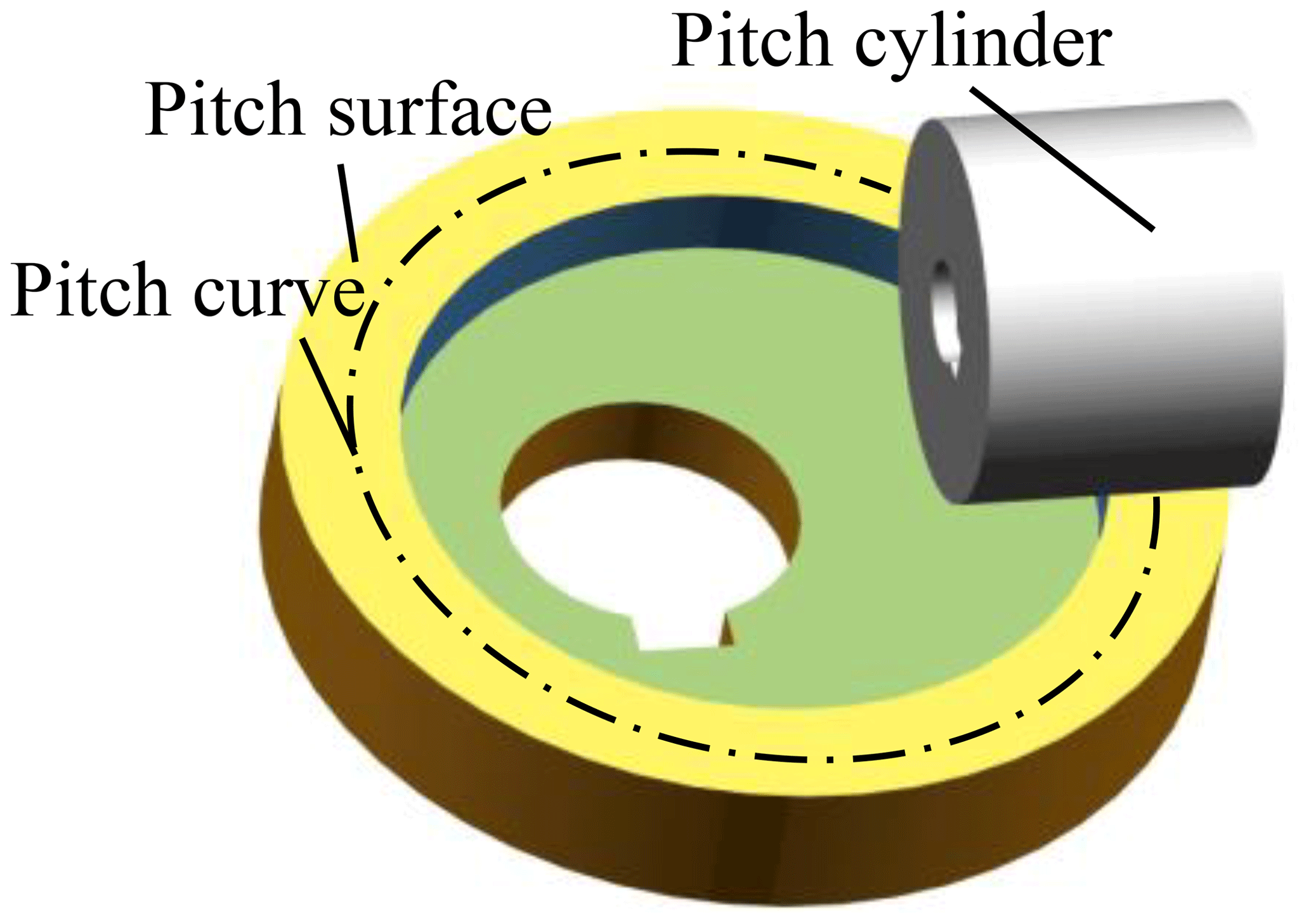
In the engagement of the NFG pair, the pitch cylinder of the pinion is tangent to the pitch surface of the NFG, as illustrated in Fig. 2. On the pitch surface of NFG, there is a noncircular closed curve called a pitch curve, which keeps pure rolling on the surface of the pitch cylinder of pinion; thus, the transmission ratio of the gear pair can be written as follows:
where ω1 and ω2 represent rotational velocity of the pinion and the NFG respectively, r1 is referred to as the pitch circle radius of the pinion, and r2 and ϕ2 are specified as the vector radius and the polar angle of the noncircular pitch curve of the NFG.
In conventional machines, a serial mechanism composed of a pair of cylinder gears and a pair of noncircular gears is usually used to both reduce the rotational velocity of the motor and achieve a variable output speed, as shown in Fig. 3. The NFG pair in Fig. 1 can implement the function of the gear train set in Fig. 3. Using the NFG pair to replace the serial gear mechanism in mechanical equipment could reduce half of the weight and space and improve the efficiency of the transmission system (Liu et al., 2017).

The mathematical models of the pitch curve and the tooth surface of the NFG were given in the literature (Liu et al., 2019) and are not repeated here. The main topic of this paper is the nonlinear dynamic behavior of the NFG under multifrequency periodic excitation.
2.2 Multifrequency parametric excitation
The NFG is a special kind of noncircular gear. However, it still transmits power by tooth meshing like circular gears. So, there are three typical kinds of internal excitations in the NFG, namely the meshing stiffness, the static transmission error and the meshing shock excitation. In addition, the position of the relative instantaneous center varies with the rotation of the gears; hence, a special internal excitation appears in gears with the changeable transmission ratio, which is named the instantaneous center activation (Liu et al., 2019).
The NFG pair is simplified to the model shown in Fig. 4. The pinion is modeled as a cylindrical rigid body, with constant rotational radius rb1, which represents the base circle radius of the pinion. The NFG is represented by a rigid body with variable vector radius r2, as shown in Fig. 4a. The contacting teeth between the gears are represented by a linear spring and damping element. For the convenience of analysis, the damping is temporarily omitted in Fig. 4. At any point in time, the direction of the meshing force between the teeth is the same as that of the acting force of the spring. In Fig. 4a, one end of the spring is tangent to the cylinder at point B. The other end of the spring is attached to the equivalent rigid body of the NFG at the relative instantaneous center M, which is on the pitch curve of the NFG. Since the profile of the pinion is straight involute, the direction of the contact force between the teeth or the acting force of the spring is the same as that of the common normal line between the teeth, which is perpendicular to the axis of rotation of the pinion, i.e., axis z1. The three-dimensional model in Fig. 4a can be simplified to the two-dimensional in Fig. 4b, where the angle α between the spring and the pitch surface is the pressure angle of the pinion.
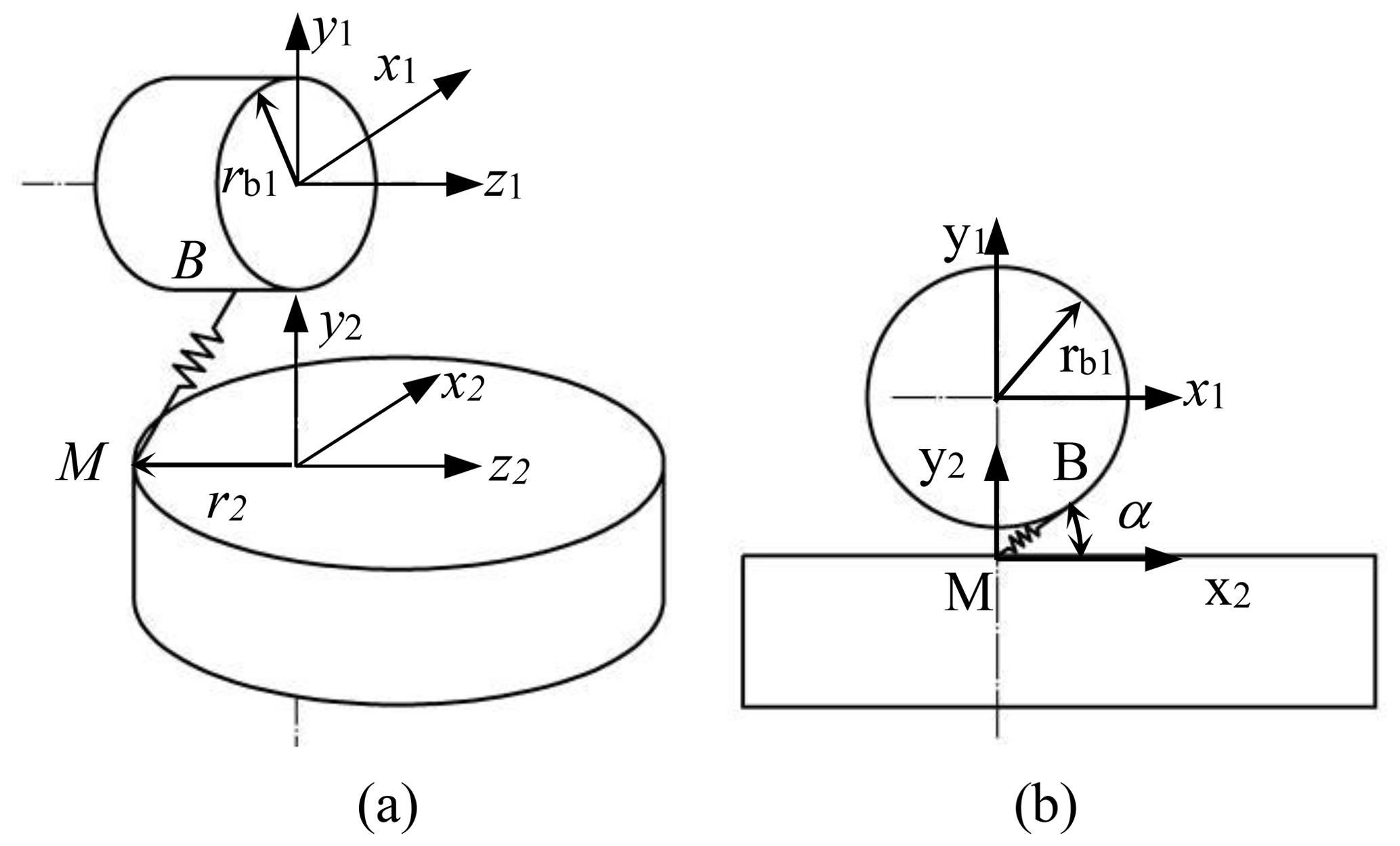
We define the rotational angle of the NFG pair yielding to the theoretical transmission ratio as the rigid angle. The rotational angle caused by the elastic formation of teeth is specified as the elastic angle. In the engagement, the real rotational angle of the gears is the sum of the rigid and the elastic angle. When the NFG pair rotates in the theoretical transmission ratio i12, the equivalent spring in Fig. 4a will move along the direction parallel to axis z1 with invariant length. The rigid angles do not change the deformation of the spring, which only depends on the elastic angles.
Then, the relative displacement of the spring in Fig. 4 can be written as follows:
where q1 and q2 represent the elastic angles of the pinion and the NFG. The elastic meshing force F between the teeth of the gears is represented as follows:
where km is the meshing stiffness of the gears. It can be seen from Eq. (3) that time-varying r2 will lead to the change in the meshing force, even if km is constant. That is the so-called instantaneous center excitation, which is a parametric one like the time-varying meshing stiffness. The frequency of the instantaneous center activation is , while the frequency of the meshing stiffness is , where ij=Z2/Z1, Z1 and Z2 are the number of teeth of the pinion and the NFG. For a common NFG pair, the frequency of the meshing stiffness is 40–100 times than that of the instantaneous center. Thereby, a special compound parametric excitation with multiple frequencies arises in the NFG pair.
2.3 Nonlinear dynamic model of NFG
Consider a lumped parameter model consisting of the meshing stiffness, the meshing damping, the static transmission error and the tooth backlash of the NFG pair in Fig. 5. rb2 is the radius of the equivalent base circle of the NFG, which is expressed by rb2=r2cos α. km and cm represent the meshing stiffness and damping, e(t) represents the static transmission error, T1 and T2 are the torques acting on the pinion and the NFG, and b is the half of the backlash between teeth.
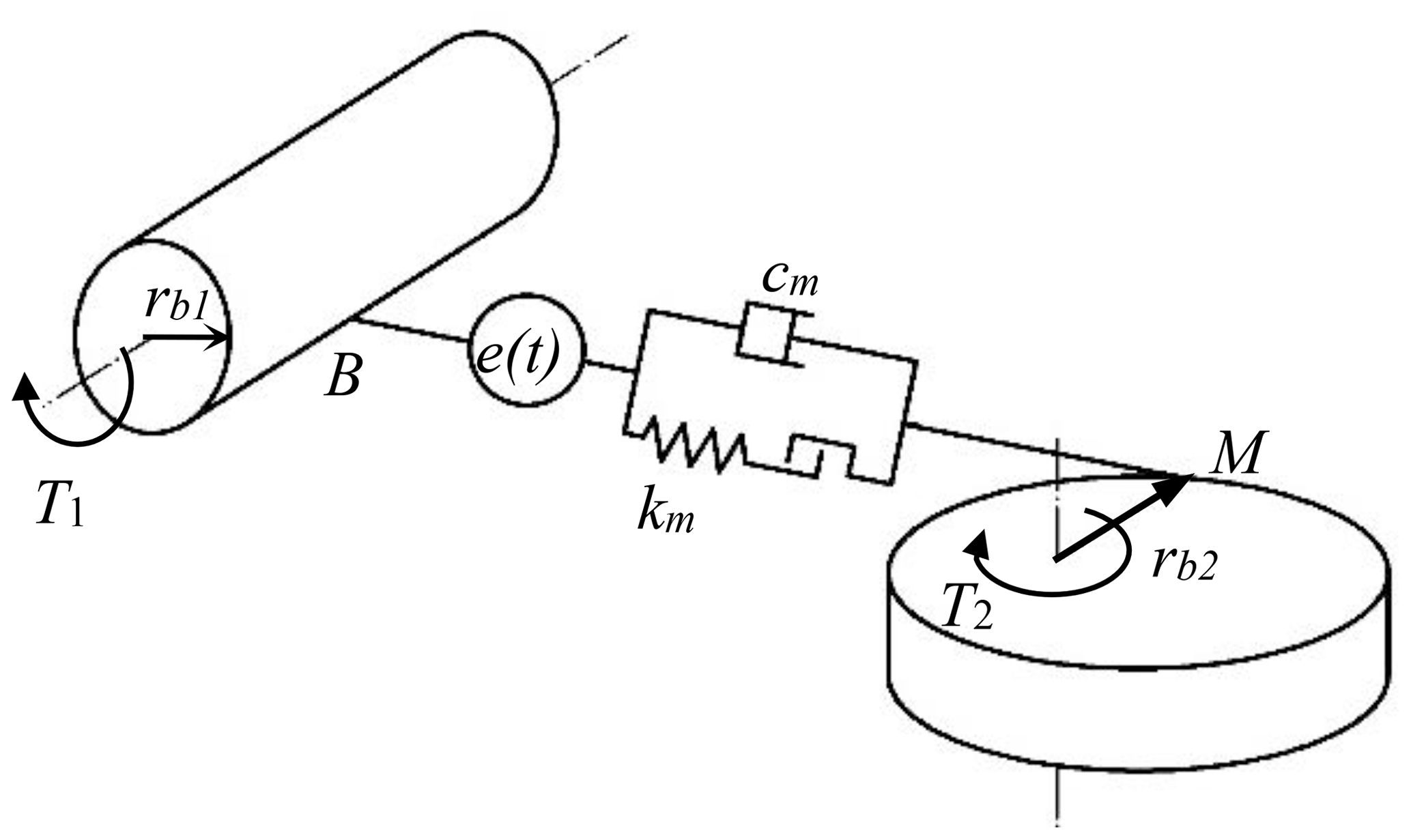
Using Newton's second law of motion, the differential equations of motion of the NFG pair are deduced as follows:
where I1 and I2 are the moments of inertia of the pinion and the NFG, and θ1 and θ2 represent the rigid angles of the pinion and NFG.
Let the pinion rotate at a given speed. The deformations of the contacting teeth of the two gears only generate the elastic rotational angle of the NFG. Substituting q1=0 into Eq. (4) results in a differential equation of torsional vibration of the NFG with a single-degree-of-freedom as follows:
The meshing stiffness of the gears, km, can be represented in Fourier series form as the following equation:
where k0 represents the constant of the meshing stiffness, k2n−1 and k2n are the amplitudes of the variables of the meshing stiffness, and ωe is called the angular frequency of the meshing stiffness excitation. The static transmission error is given by the following:
where e0 represents the constant of the error, e2p−1 and e2p are the amplitudes of the variables of the error. The radius of the equivalent base circle of the NFG can be simplified as follows:
where L and β are specified as the mean and the change rate of the base circle radius of the NFG, and ωc is the angular frequency of the instantaneous center excitation. Set and τ=ωnt and assume that the meshing damping cm is time invariant. Then the dimensionless expression of Eq. (5) can be written as the following equation:
where ζ represents the meshing damping ratio, ωn represents the natural frequency of the single-degree-of-freedom model, is the dimensionless static transmission error, F(τ) is a dimensionless function with respect to τ, and f(q) is the dimensionless describing function of the relative displacement between the contacting teeth.
ωn, and f(q) have the following expressions:
where is the dimensionless tooth backlash, which is given by .
2.4 Solution of nonlinear differential equation
Assume that Eq. (9) has a periodic solution q, which contains the harmonics with the frequencies of the internal and external excitations. It can easily be seen from Eq. (9) that the angular frequency of the static transmission error is , the angular frequency of the second derivative of rigid angle is , and the function F(τ) contains the following angular frequencies: , , , and , where and . Then, take the solution of Eq. (9) in the following form:
where z0 and z1…z10r+4 represent the constant coefficients of the harmonics in the periodic response q. Since , where Z2 is a positive integer, the period of dynamic response q can be expressed by ; hence, the deformation of the equivalent spring between the gears satisfies the equation . The periodic function f(q) could be expressed by a Fourier series. Considering that the left and right side of Eq. (9) should keep harmonic balance, we give the description of f(q) with the same frequency components as q in the following:
where f0, f1…f10r+4 represent the constant coefficients of the harmonics in the periodic function f(q).
Substituting Eqs. (11)–(12) into Eq. (9), we can obtain a algebraic equation set, si=0 (where ), based on the harmonic balance method.
2.5 Discrete Fourier transformation
In the algebraic equation set si, the coefficient of the expression of the steady-state response q, zi, is the unknown. In addition, the coefficient of the harmonics of f(q), fi, is the function of the unknown zi, which should be described before solving the equations si.
First, discretize the Eq. (13) by taking the following:
where m and M are both positive integers, with . Substituting Eq. (15) and into Eq. (13) leads to qm; that is the discrete time series of the steady-state response of the gear system. Substituting qm into Eq. (12) results in the discrete time series of the backlash nonlinearity function f(q) as follows:
Then, gm is processed by a discrete Fourier transformation to obtain the expression of fi as follows:
Finally, substituting Eq. (17) into the equation set si=0 could lead to a nonlinear algebraic equation set with respect to the unknown zi. Using a quasi-Newton method to solve the nonlinear equations has the advantage that the inversion calculation of their Jacobian matrix can be canceled in each iteration, which will improve the computational efficiency greatly. Based on Broyden's method, the nonlinear equation set si=0 is solved to obtain the periodic response q of the NFG pair under a set of given initial value of zi.
3.1 Parameters of NFG pair
Set the transmission ratio of the NFG pair as follows:
where ε represents the eccentric ratio for determining the variation range of the transmission ratio.
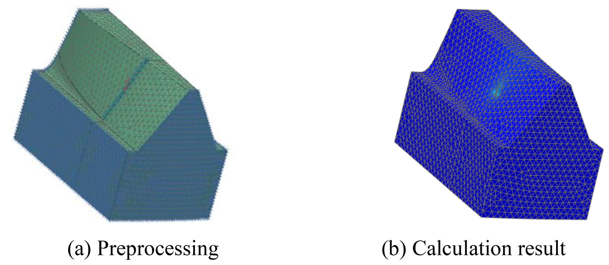
Since the tooth shapes of the NFG are complicated and different from each other, the finite element method is applied to compute the mesh stiffness of the gears. Figure 6a shows a single-tooth model of the NFG in a finite element software, which is constructed based on the meshing theory in the literature (Liu et al., 2019). The teeth of the NFG and the pinion contact at a point. A unit normal force is added at the meshing point of the two tooth surfaces. Correspondingly, the tooth deformation is calculated by the finite element software, as shown in Fig. 6b. We extract the deformation data, s, at the meshing point. The stiffness of the gear tooth at this position can be computed by . Then, the stiffness curve of a single tooth of the NFG can be fitted by stiffness values at different meshing points. In a similar way, the stiffness curve of a single tooth of the pinion can be obtained.
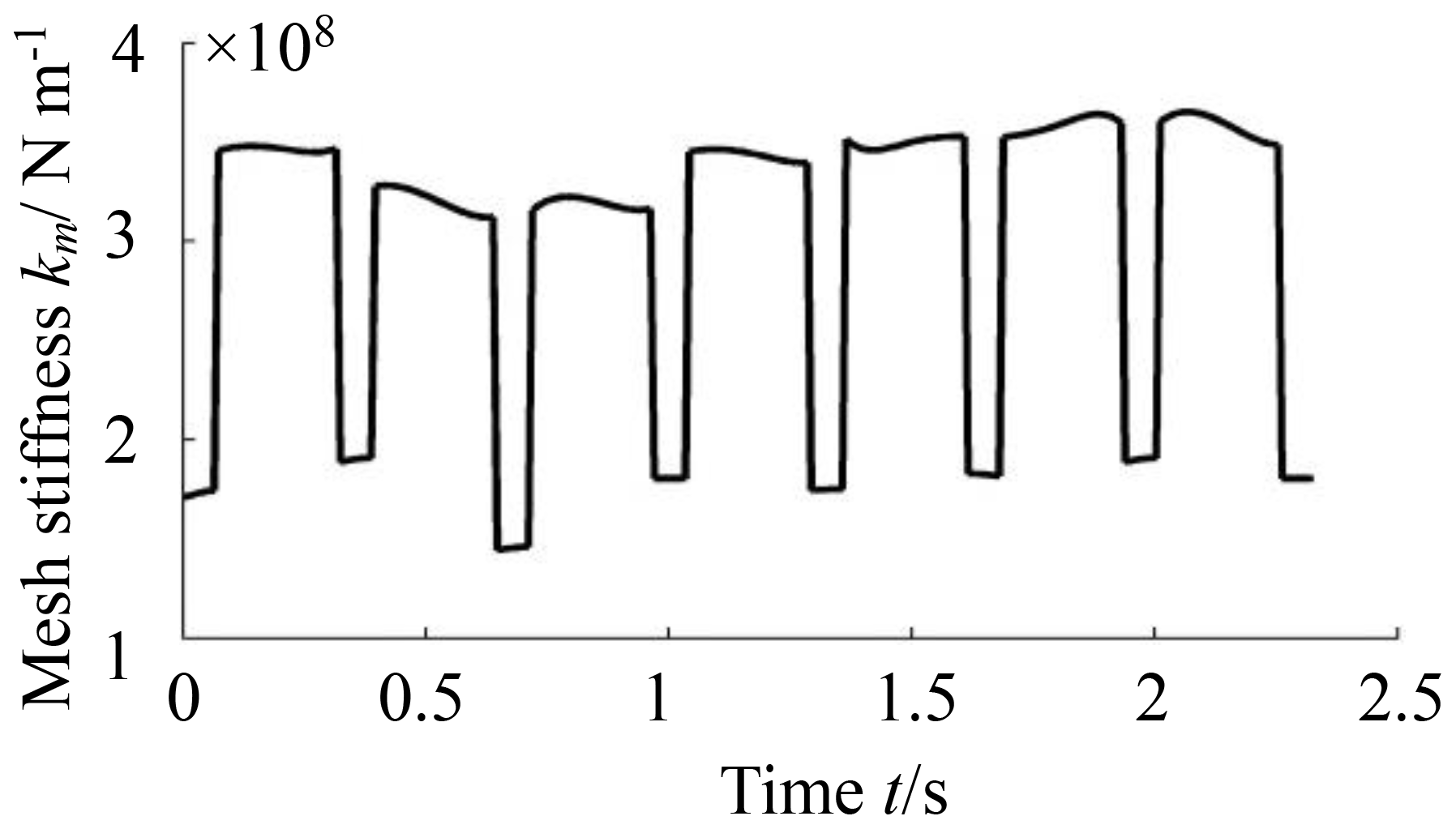
Dealing with the contacting teeth of the NFG and the pinion as serial springs, we can obtain the meshing stiffness curves of a pair of teeth of the gears. In an engagement, two pairs of the meshing teeth can be represented by two parallel springs. According to the alternation rule of one and two pairs of teeth, the synthesizing meshing stiffness curves of the gears are obtained, as shown in Fig. 7, where the rotational speed of the pinion is 1 rad per second. Due to the asymmetry of the teeth of the NFG, the stiffness curve in every meshing period is various.
In most cases, the harmonic of the fundamental frequency of excitations plays a leading role in the steady-state response of the dynamic system, which is also given special attention in practice. With the consideration of the convenience of the calculation and actual requirement in engineering, the expressions of the meshing stiffness and static transmission error are rewritten on the basis of Eqs. (6)–(7) as follows:
where kr and er are specified as the amplitudes of the fundamental frequency component of the meshing stiffness and transmission error, and φm and φe are the phase angles of the meshing stiffness and error. k0 and kr can be calculated by a discrete Fourier transformation of the synthesizing meshing stiffness in Fig. 7. Without a consideration of the effect of the two-phase angles on the vibration of the NFG, we take them as being and φe=0; then, the second derivatives on the right-hand side of Eq. (9) can be deduced as follows:
Let the load torque acting on the NFG be constant. Expand Eq. (20) with a Fourier series, and substitute its first two terms into the right-hand side of the Eq. (9) to derive the following expression:
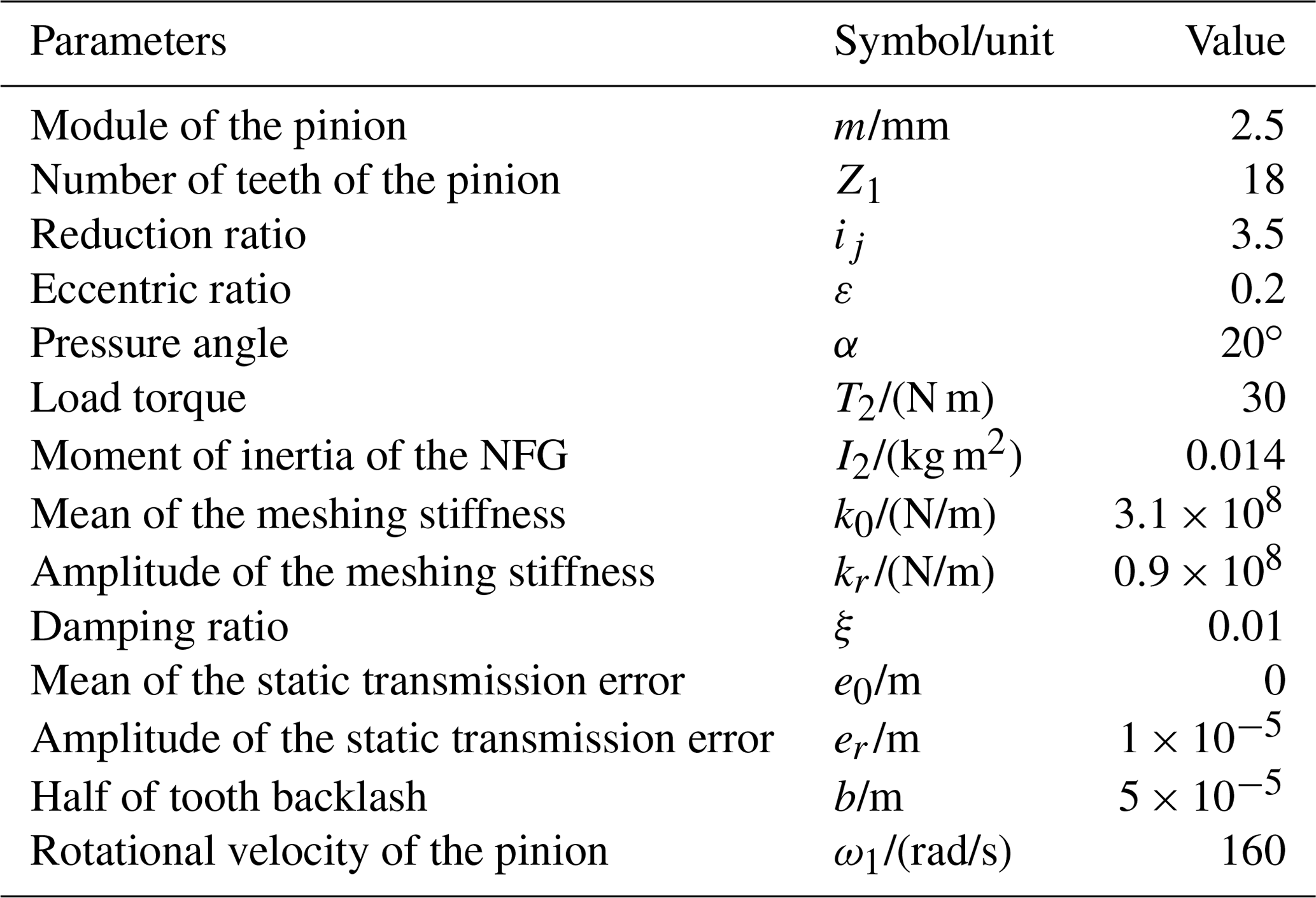
where , , and B1 and B2 represent the amplitudes of the first two terms in the Fourier series of Eq. (20). The parameters of the NFG pair are given in Table 1.
3.2 Rattle phenomenon
The dynamic equation in Sect. 3 is utilized for the analysis of the nonlinear rattle behavior of the NFG. Since the expressions of the meshing stiffness and the transmission error take the first-order harmonic alone, the variable R in Eqs. (13)–(14) is equal to 1, resulting in 15 unknown variables in the equation set si=0. According to the solution method in Sect. 4.2, the dynamic responses of a NFG pair, with the parameters given in Table 1, are obtained.
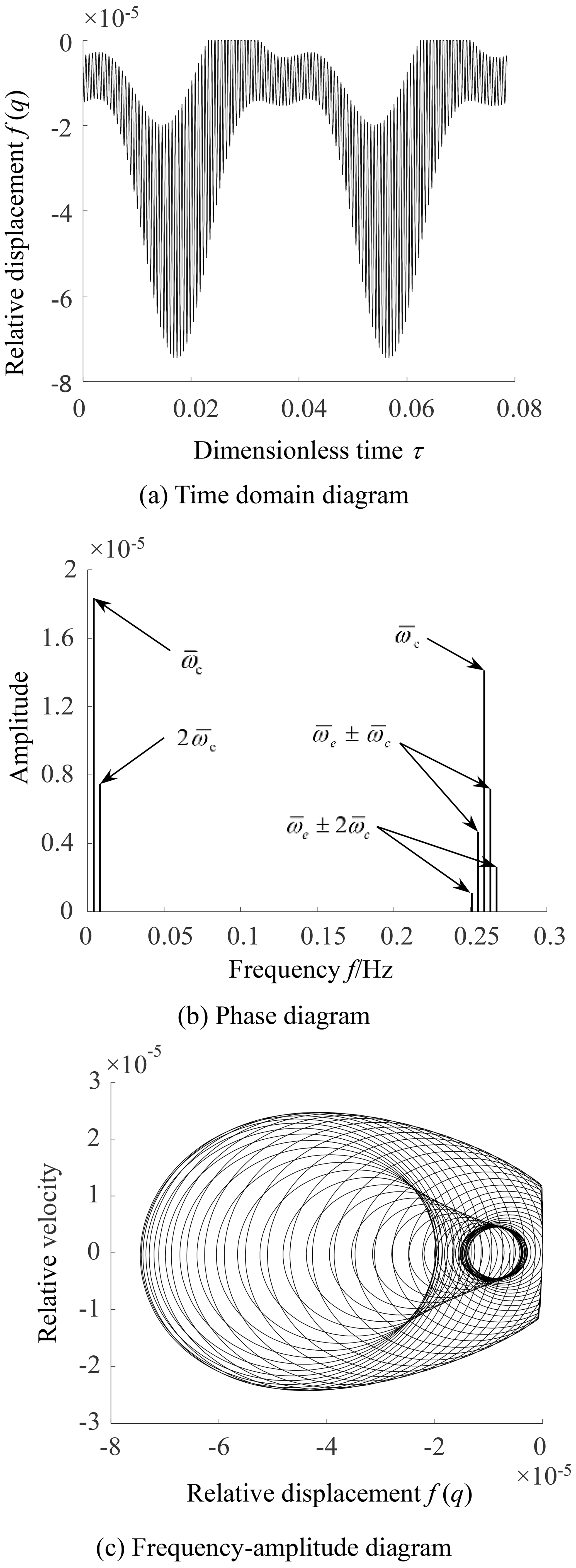
Figure 8 illustrates the time domain diagram, phase diagram and the frequency–amplitude diagram of the relative displacement between gears. It can be seen from Fig. 8a that the values of the relative displacement are negative or zero. At the same time, there exits a sudden change in relative velocity at f(q)=0 in the phase diagram of Fig. 8b, which means that the rattle behavior occurs between teeth. Since the relative displacement does not exceed zero, the rattle phenomenon only occurs on the driving side of the tooth surface, which is called a unilateral rattle. Figure 8c shows the amplitudes of each excitation frequency in which the amplitudes corresponding to the instantaneous center excitation and the meshing stiffness excitation are relatively large. It indicates that they play a major role in the rattle vibration of the NFG. As the frequency of the instantaneous center excitation is far less than the frequency of the meshing stiffness, the time domain response curve in Fig. 8a presents the characteristics of the superposition of low-frequency vibration and high-frequency vibration.
Reduce the input velocity ω1 to 140 rad per second and keep the other parameter unchanged in Table 1. The dynamic responses are obtained, as shown in Fig. 9. From Fig. 9a and b, it can be seen that the values of the relative replacements are all less than zero, which means the gear system vibrates periodically without rattling. At the same time, the amplitudes corresponding to each frequency all reduce slightly in Fig. 9c, which leads to the vibration of the NFG weakening, as shown in Fig. 9a.

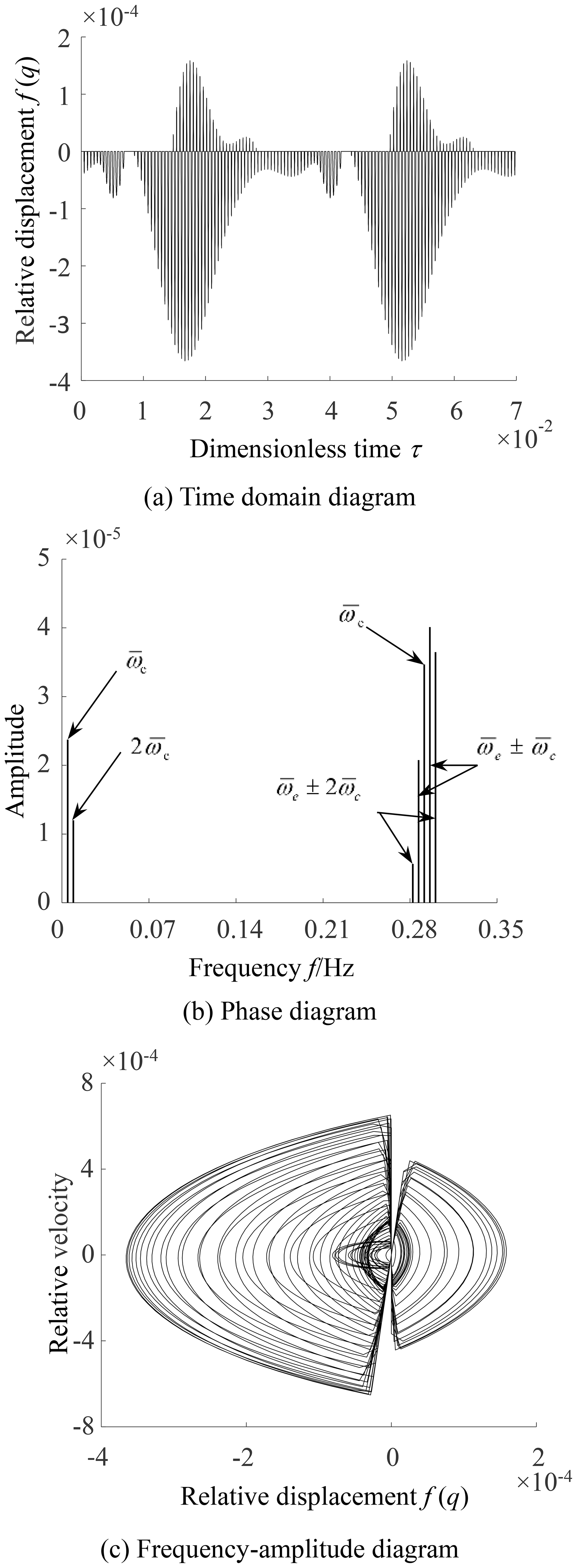
When the input speed ω1 increases to 180 rad per second, there are positive and negative values in the relative displacements, as shown in Fig. 10a, and sudden changes occur at f(q)=0 in Fig. 10b. It indicates that the gears will contact on the non-driving side of the tooth surfaces after separation from the driving side. The bilateral rattle appears in the engagement of the NFG pair. The amplitude corresponding to each excitation frequency increases greatly, as seen in Fig. 10c, which shows that the bilateral rattle would result in a serious deterioration of the dynamical performance of the NFG.
From the above analysis, it can be seen that, under the combined excitation of the time-varying instantaneous center and meshing stiffness, the vibration behavior of a non-circular face gear is more complex than that of a circular gear. The change in velocity will lead to different rattle vibration behaviors. In order to further reveal the evolution law of the rattle vibration behavior of non-circular face gear, the influences of parameters such as the input speed, eccentricity, static transmission error, meshing stiffness and load on the rattle behavior are studied by the control variable method below. The parameter rsv is introduced to describe the rattle state. When rsv is 0, 1 or 2, it represents the no-rattle, unilateral rattle and bilateral rattle of gears respectively. In addition, ppv is referred to as the peak-to-peak value of the steady-state response that is used to reflect the degree of gear vibration. By calculating the rsv and ppv of NFG drive under different system parameters, the evolution characteristics of the rattle vibration behavior of the gear were analyzed.
3.3 Effect of input speed on rattle
Let the rotational velocity of the pinion increase from 100 to 250 rad per second, and let the values of the other parameters in Table 1 be invariable. Figure 11a shows the change in the rattle state along with ω1. It can be observed that the NFG runs without rattle at the low-input velocity, where rsv is equal to 0. As ω1 increases to 150 rad per second, the unilateral rattle behavior appears, which continues until ω1=170 rad per second. Then the NFG will change to a bilateral rattle state with a higher input velocity. The results indicate that the NFG undergoes the non-rattle, unilateral rattle and bilateral rattle state in succession as the input speed ω1 increases.
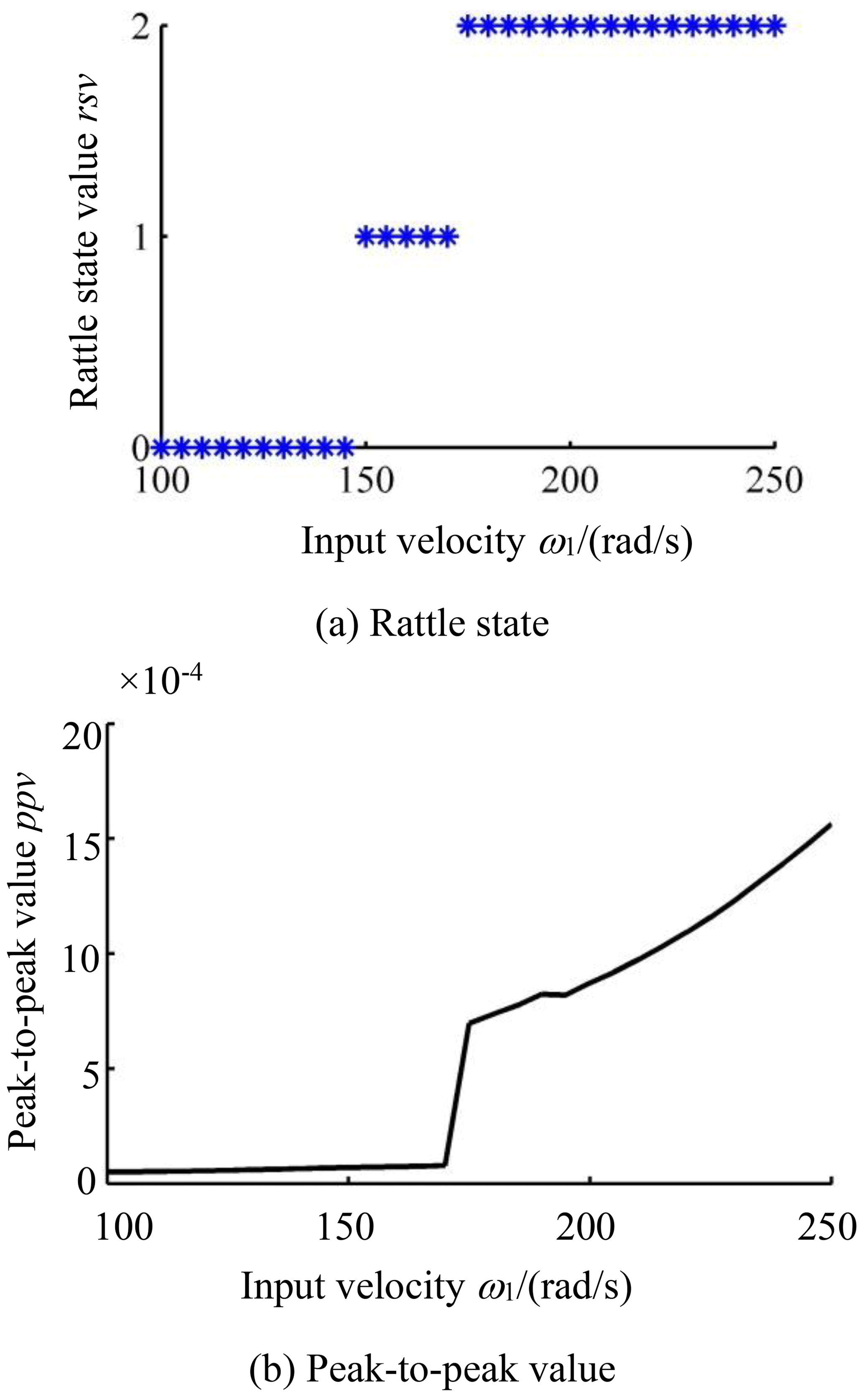
The peak-to-peak value of the vibration of the NFG varying with ω1 is illustrated in Fig. 11b. In the non-rattle and unilateral rattle vibration, ppv grows gradually with the increase of the input speed. However, at the start of the bilateral rattle, a sudden increase occurs in the curve of ppv. Then it continues to grow along with the input velocity. The results show that, at the outset of the bilateral rattle, the vibrational amplitude of the NFG jumps suddenly, and in the bilateral rattle state, the vibrational amplitude increases more quickly.
3.4 Effect of static transmission error on rattle
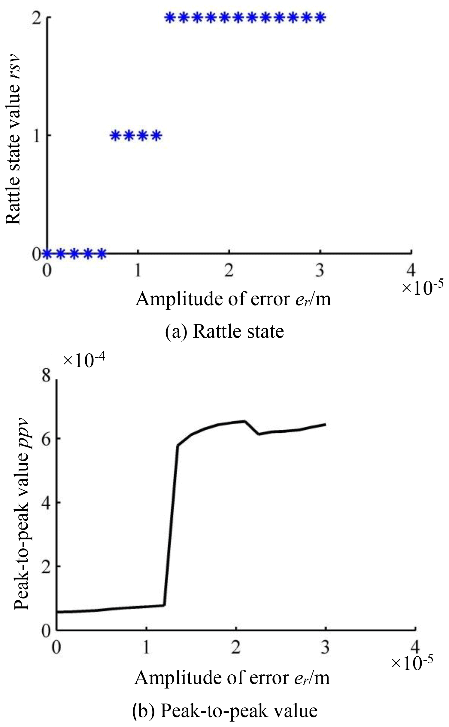
Figure 12a depicts the change in the rattle state, along with the amplitude of the transmission error. As er increases, the NFG undergoes non-rattle, unilateral rattle and bilateral rattle vibration in succession and maintains the bilateral vibration state in the end. These results indicate that low machining accuracy will cause rattle vibration easily for the NFG. Figure 12b gives the curve of ppv, varying it with er. First, in the process of non-rattle and unilateral rattle vibration, the ppv of the NFG grows slightly with the increase in er. As the bilateral rattle arises, ppv increases suddenly, which means that an amplitude jump occurs in the dynamic response of the NFG. Then, as the amplitude of transmission error continues to increase, the ppv slowly rises. It can be concluded from the above results that improving the processing accuracy is an effective way of eliminating the rattle and reducing the vibration of the NFG.
3.5 Effect of eccentric ratio on rattle
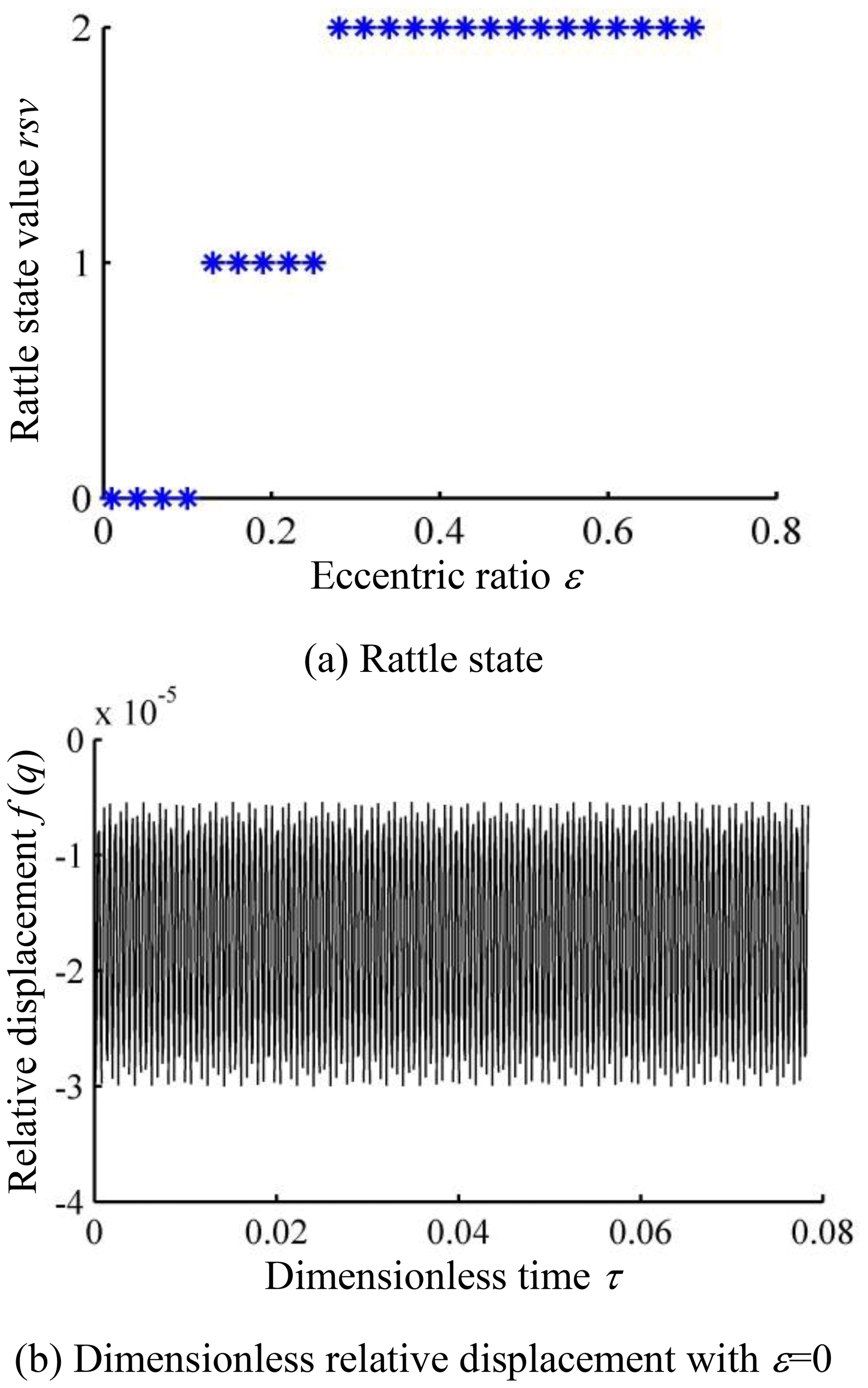
The variation in the rattle state with the eccentricity of the NFG is investigated. Figure 13a shows that the NFG also undergoes the three rattle states with the increase in eccentric ratio. The eccentric ratio is the essential difference between noncircular and circular face gear. When ε=0, the noncircular face gear becomes circular. The dynamic response is illustrated in Fig. 13b. Comparing it to Fig. 8a, we can see that the vibration amplitude of the circular face gear is much less than that of the NFG. Correspondingly, the rattle vibration appears more easily in the noncircular face gear than in the circular gear, and the greater the eccentricity is, the easier the NFG is to rattle.
The peak-to-peak value of the NFG grows with the increase in ε when it undergoes non-rattle and unilateral rattle vibration, as shown in Fig. 13c and suddenly increases when the bilateral rattle appears. Then, as the eccentric ratio increases, the ppv of the NFG drops significantly. However, it is still in the bilateral rattle state. For a NFG with a large eccentric ratio, we could decrease the input speed or increase the machining accuracy to prevent the tooth rattle.
3.6 Effect of time-varying meshing stiffness on rattle
We define the ratio of kr to k0 in Eq. (19) as the amplitude coefficient of the mesh stiffness, ak. Figure 14a shows that the NFG maintains a unilateral rattle state with the increase in ak from 0.1 to 0.8. We take the rotational velocity of the pinion as ω1=140 rad per second. The NFG keeps a non-rattle state all the time as ak increases, as shown in Fig. 14a. Through further calculation, we find that, under some critical conditions such as ω1=145 rad per second, the variation in the ak could lead to a change in the rattle state of the NFG. This demonstrates that the fluctuation of the meshing stiffness has less of an effect on the transformation of the rattle state of the NFG than the three preceding parameters do. However, ppv curves in Fig. 14b show that the vibrational amplitudes of the NFG will rise, obviously, as the amplitude coefficient of the mesh stiffness increases at different input velocities.
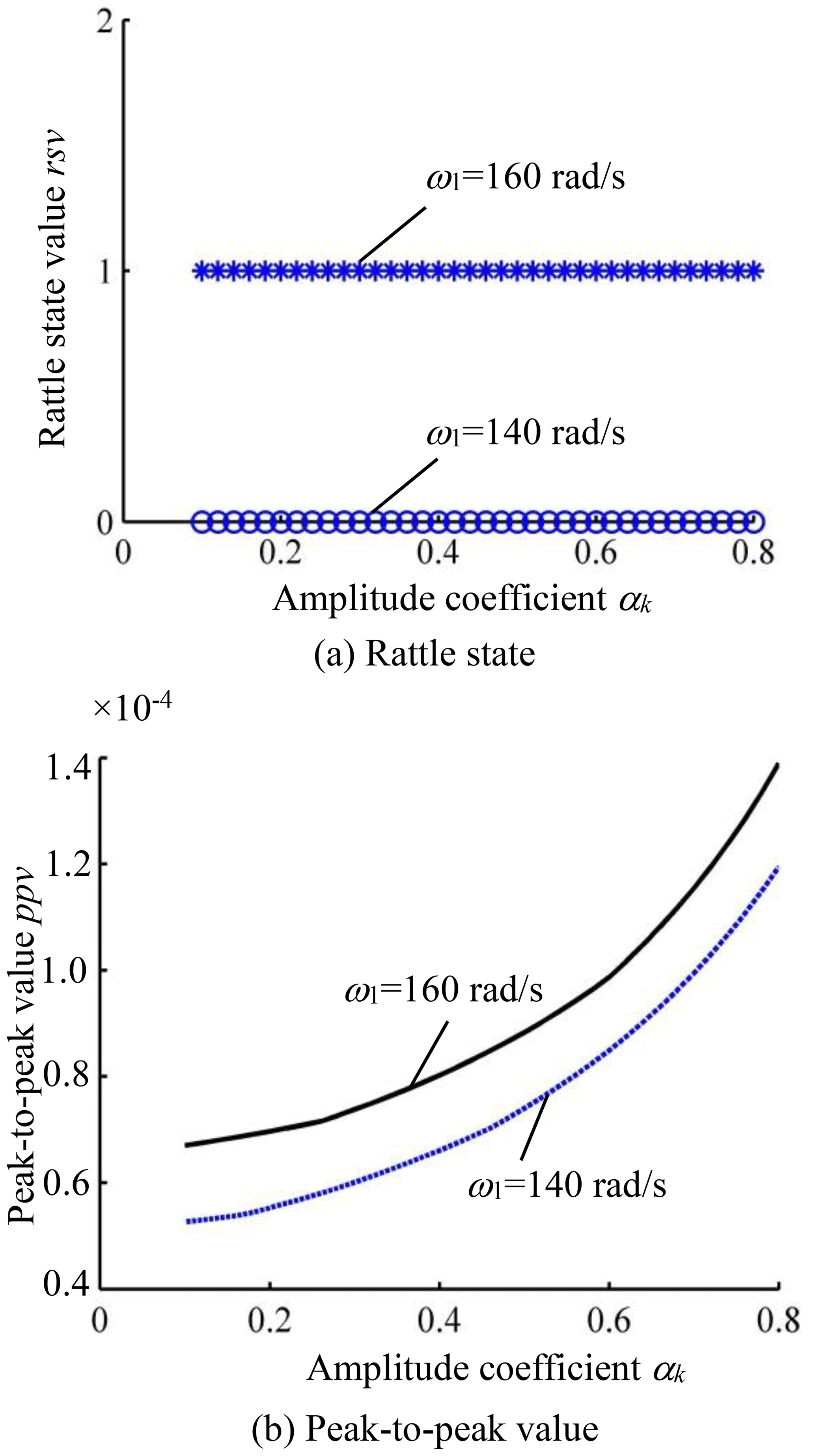
Figure 14Change in vibration with the amplitude coefficient of meshing stiffness at different input velocities.
3.7 Effect of load torque on rattle
Let the load torque, T2, increase from 0 to 40 N per meter and keep the other parameters invariant, as in Table 1. The rattle state of the NFG with the increase in the load torque is shown in Fig. 15a. When T2 is less than 12 N per meter, there is a bilateral rattle in the engagement of the NFG. As T2 rises from 12 to 20 N per meter, the gear is in a unilateral rattle state. When T2 increases to 20 N per meter, there is no rattle. In the case of light or no load, the rattle vibration appears in the transmission of the NFG, which is the same as that of ordinary circular gears. However, due to the instantaneous center excitation, the rattle vibration happens more easily in the NFG than in the circular gears.
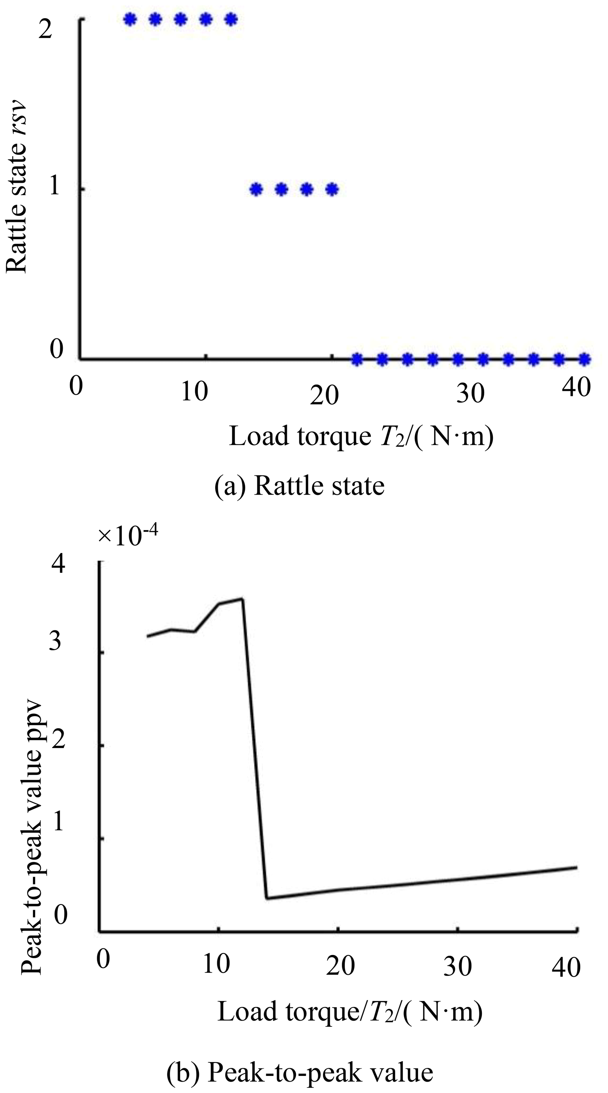
Figure 15b shows the ppv curve of the dynamic response of the NFG as the load torque increases. In the bilateral rattle state, the ppv grows slowly with the increase in T2. When the vibration state changes from the bilateral to the unilateral rattle, the amplitude of ppv drops sharply. Then, ppv gradually raises with the increase in T2. The results indicate that a small load torque is prone to generating a bilateral rattle in the drive of the NFG, which will lead to excessive vibration. We could increase the load torque appropriately to prevent the rattle phenomenon.
3.8 Experimental validation
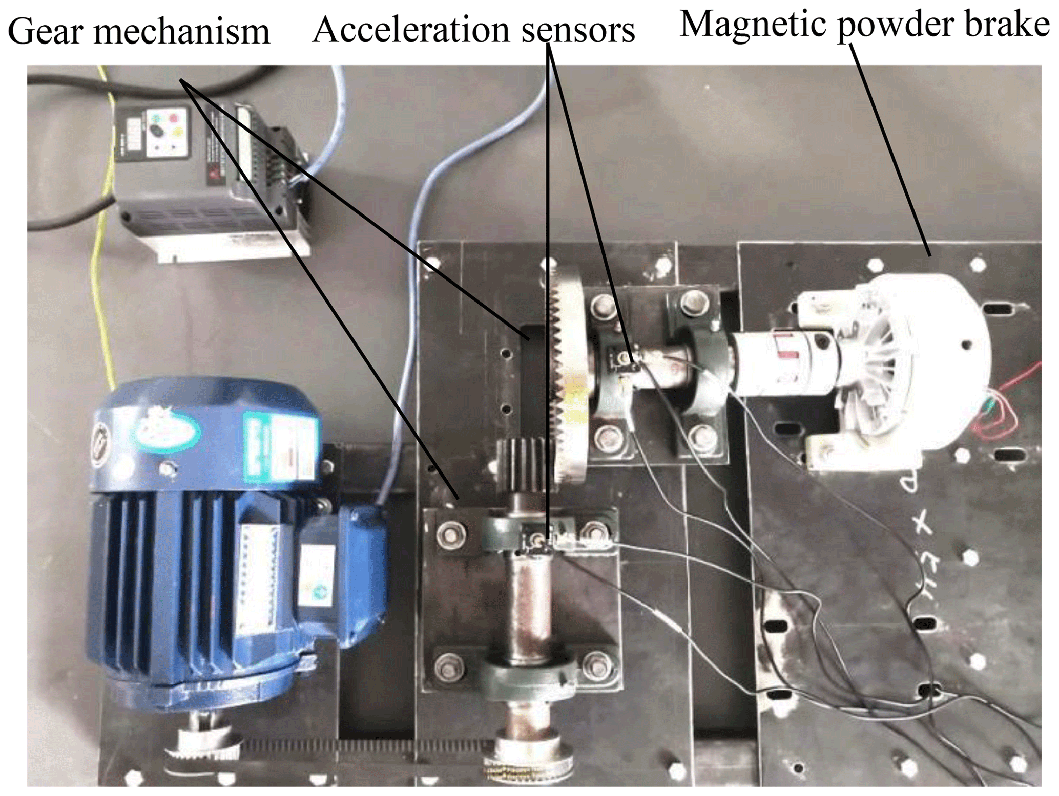
A NFG is manufactured by a three axis CNC milling machine, according to the design parameters in Table 1, whose vibration test platform is shown in Fig. 16. A variable frequency motor connects to the pinion with a pair of synchronous pulleys. The NFG is connected to a magnetic powder brake by a couple. Considering that the torsional vibration of the gears would propagate along the supporting bearings, we apply the rectilinear vibration of the bearings to reflect the torsional vibration of the NFG. There are two three-axis acceleration sensors fixed on the bearings of the pinion and the NFG. The one measures the radial vibration of the pinion, while the other measures the radial and axial vibration of the NFG. The vibration signals of the NFG under different working conditions can be tested by adjusting the motor velocity and brake torque.
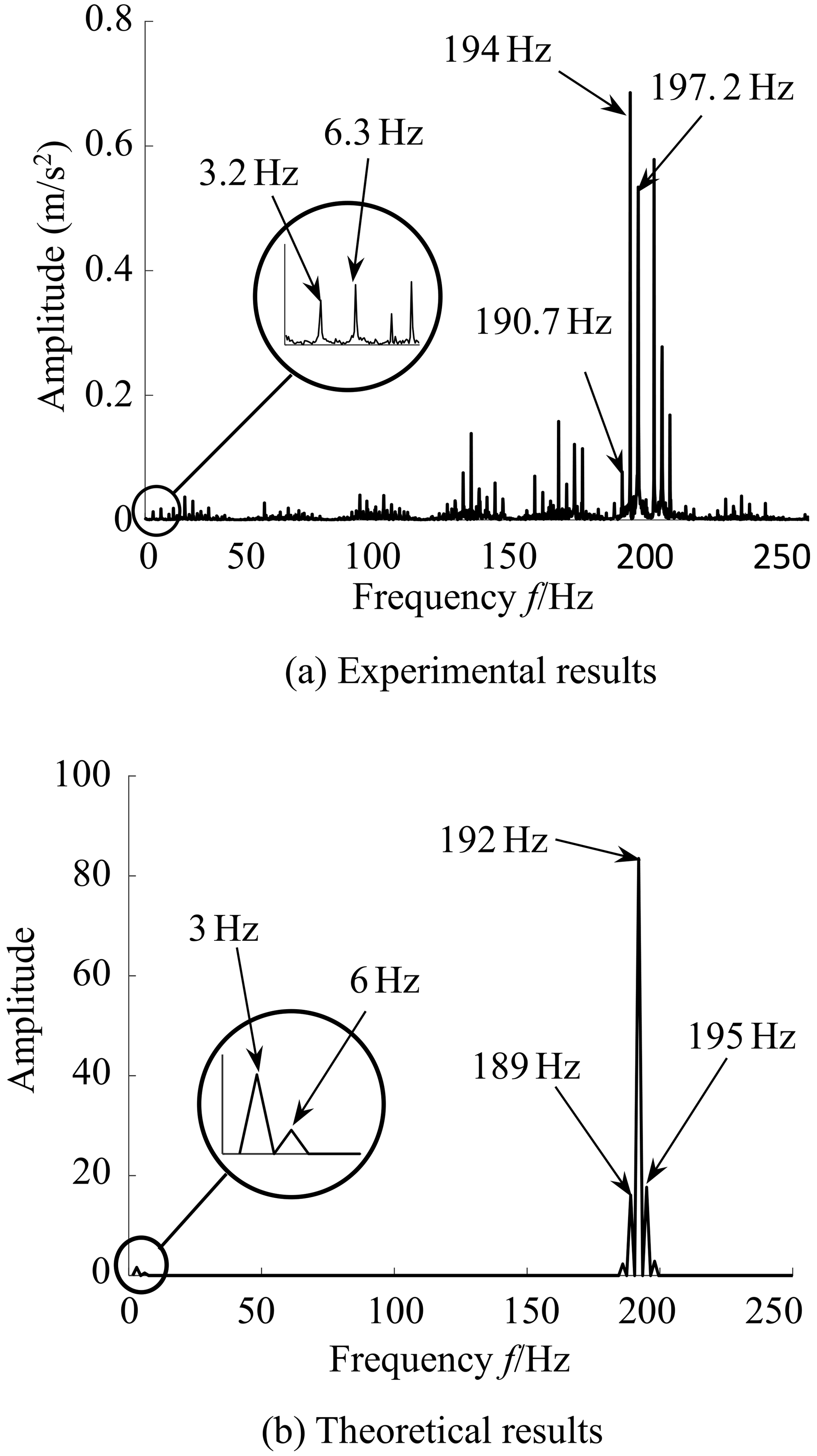
Since the experimental results are the linear vibration data on the bearing seat in Fig. 16, and the theoretical results are the dimensionless torsional vibration data of the NFG, they cannot be compared with each other in the time domain. Figure 17 gives a comparison between the experiment and simulation results in frequency domain in which the rotational velocity of the motor is 864 rpm (revolutions per minute), the reduction ratio of the synchronous belt drive is 1.3, and the load torque is 3 N per meter. It can be seen from Fig. 17 that the theoretical frequency values of instantaneous center excitation and mesh stiffness excitation are 3 and 192 Hz, respectively, while the measured values are 3.2 and 194 Hz, respectively. In addition, the double frequency of the time-varying instantaneous center, the sum and difference frequency of time-varying instantaneous center and the meshing stiffness in Fig. 17a are close to those in Fig. 17b. The frequency components of the theoretical results are in good agreement with those of the experimental results.
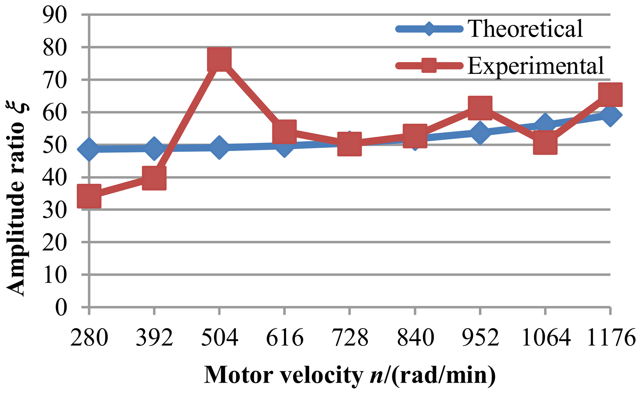
To compare the amplitude of the spectrum of the theoretical and experimental vibration responses, a dimensionless parameter, called the ratio of amplitude, is introduced. Considering that the fundamental frequency plays an important role in the vibration of the system, the ratio of amplitude is expressed by the following:
where Ae and Ac represent the amplitude of meshing frequency fe and that of instantaneous center frequency fc in the frequency–amplitude diagram. Increasing the motor speed from 280 to 1176 rpm, the theoretical and experimental vibration data of NFG under different excitation frequencies are shown in Table 2. It can be seen that the theoretical values of the instantaneous center and meshing frequency agree with their experimental values.
Furthermore, the theoretical and experimental amplitude ratio data are illustrated in Fig. 18. With the increase in the motor speed, the two curves gradually match. The main reason for the larger error at low speed is that the excitation at low speed is relative small. The meshing vibration of the gear attenuates after it is transmitted along the bearing, which results in a larger error of the measurement data on the bearing seat. When the motor velocity exceeds 616 rpm, the experimental results are found to be in agreement with the calculated ones, which could verify the correctness and validity of the presented theoretical model and solution.

The internal excitations of a new gear pair comprised of a pinion and a noncircular face gear are investigated. Considering the multifrequency parametric excitation and backlash nonlinearity, the dynamic model of the NFG pair is established, which is solved by harmonic balance method and discrete Fourier transformation. The effects of the main system parameters on the vibrational state of the gears are analyzed in detail. The results show the following:
-
The instantaneous center excitation in the NFG pair is low frequency and time varying, which belongs to a parametric type of excitation. It compounds with the time-varying meshing stiffness of the gears to form a complex multifrequency parametric activation.
-
The eccentric ratio, input speed and error amplitude have a great influence on the rattle state of the NFG pair. As the three parameters increase, the NFG undergoes non-rattle, unilateral rattle and bilateral rattle vibration in succession. The effect of the fluctuation of the meshing stiffness on the rattle state is smaller. Under some critical condition, the rattle state of the gear will change with the increase in the amplitude coefficient of the mesh stiffness.
-
In the state of non-rattle and unilateral rattle, the peak-to-peak values of the dynamic response of the NFG grow gradually with the increase in the eccentric ratio, input speed and error amplitude. At the start of bilateral rattle vibration, a jump phenomenon occurs on the ppv curve, which means that the vibration of the gears is suddenly enhanced at this instant. In addition, ppv rises greatly with the increase in the amplitude coefficient of the mesh stiffness, which has a big influence on the vibration amplitude of the gears.
All data included in this study are available upon request from the corresponding author.
DL conceived the idea, developed the theory and acted as corresponding author. GZ performed experiments and simulations and analyzed the results. ZL wrote the paper.
The authors declare that they have no conflict of interest.
This article is part of the special issue “Robotics and advanced manufacturing”. It is not associated with a conference.
The authors would like to thank the National Natural Science Foundation of China (grant no. 51705444) and the University Science and Technology Research Project of Hebei Province (grant no. QN2020266) for financially supporting this work.
This research has been supported by the National Natural Science Foundation of China (grant no. 51705444) and the University Science and Technology Research Project of Hebei Province (grant no. QN2020266).
This paper was edited by Haiyang Li and reviewed by Chao Lin and two anonymous referees.
Al-shyyab, A. and Kahraman, A.: A non-linear dynamic model for planetary gear sets, Proc. Inst. Mech. Eng., 22, 567–576, https://doi.org/10.1243/14644193JMBD92, 2007.
Bahk, C. J. and Parker, R. G.: Analytical solution for the nonlinear dynamics of planetary gears, J. Comput. Nonlin. Dyn., 6, 1–15, https://doi.org/10.1115/1.4002392, 2011.
Bozca, M.: Transmission error model-based optimisation of the geometric design parameters of an automotive transmission gearbox to reduce gear-rattle noise, Appl. Acoust., 130, 247–259, https://doi.org/10.1016/j.apacoust.2017.10.005, 2018.
Cai, Z. Q. and Lin, C.: Dynamic model and analysis of nonlinear vibration characteristic of a curve-face gear drive, Stroj. Vest., 63, 161–170, https://doi.org/10.5545/sv-jme.2016.3859, 2017.
Comparin, R. J. and Singh, R.: Non-linear frequency response characteristics of an impact pair, J. Sound Vib., 134, 259–290, https://doi.org/10.1016/0022-460X(89)90652-4, 1989.
Dong, H. J., Shen, Y. W., Liu, M. J., and Zhang, S. H.: Study on the dynamic behavior of rattle in gear system with clutch, Xibei Gongye Daxue Xuebao, 22, 225–230, https://doi.org/10.3969/j.issn.1000-2758.2004.02.024, 2004.
Kahraman, A. and Singh, R.: Non-linear dynamics of a geared rotor-bearing system with multiple clearances, J. Sound Vib., 144, 469–506, https://doi.org/10.1016/0022-460X(91)90564-Z, 1991.
Lin, C. and Cai, Z. Q.: Modeling of dynamic efficiency of curve-face gear pairs, Proc. Inst. Mech. Eng., 230, 1209–1221, https://doi.org/10.1177/0954406215623308, 2016.
Lin, C., Liu, Y., and Gu, S. J.: Analysis of nonlinear twisting vibration characteristics of orthogonal curveface gear drive, J. Braz. Soc. Mech. Sci. Eng., 37, 1499–1505, https://doi.org/10.1007/s40430-014-0296-y, 2015.
Liu, D. W., Ren, T. Z., Ba, Y. B., Gu, D. D., and Yang, E. X.: Torsional vibration model and its dynamic characteristics for a noncircular gear based on separation of elastic rotating angle, J. Vib. Shock, 35, 228–233, https://doi.org/10.13465/j.cnki.jvs.2016.23.036, 2016.
Liu, D. W., Wang, G. H., and Ren, T. Z.: Transmission principle and Geometrical model of Eccentric Face Gear, Mech. Mach. Theory, 109, 51–64, https://doi.org/10.1016/j.mechmachtheory.2016.10.024, 2017.
Liu, D. W., Gu, D. D., and Liu, Z. J.: Coupled Vibration Modeling and Dynamic Characteristics of Noncircular Face Gear Drive System with Time-varying Instantaneous Center Excitation, Proc. Inst. Mech. Eng., 233, 4947–4959, https://doi.org/10.1177/0954406219841085, 2019.
Liu, X., Nagamura, K., and Ikejo, K.: Analysis of the dynamic characteristics of elliptical gears, J. Adv. Mech. Des., Syst., 6, 484–497, https://doi.org/10.1299/jamdsm.6.484, 2012a.
Liu, X., Nagamura, K., and Ikejo, K.: Vibration and noise characteristics of elliptical gears due to non-uniform rotation, J. Adv. Mech. Des. Syst., 6, 484–511, https://doi.org/10.1299/jamdsm.6.498, 2012b.
Liu, X., Nagamura, K., and Ikejo, K.: Simulation on the vibration characteristics of elliptical gears, Proc. Inst. Mech. Eng., 227, 819–830, https://doi.org/10.1177/0954406212454372, 2013.
Nikolic-Stanojevic, V., Veljovic, L., and Dolicanin, C.: A new model of the fractional order dynamics of the planetary gears, Math. Probl. Eng., 2013, 932120, https://doi.org/10.1155/2013/932150, 2013.
Shangguan, W. B., Liu, X. L., Yin, Y. M., and Rakheja, S.: Modeling of automotive driveline system for reducing gear rattle, J. Sound Vib., 416, 136–153, https://doi.org/10.1016/j.jsv.2017.07.052, 2018.
Wei, J., Sun, W., Chu, Y. S., and Zeng, J.: Bifurcation and chaotic characteristics of helical gear system and parameter influences, Harbin Gongcheng Daxue Xuebao, 34, 1301–1309, https://doi.org/10.3969/j.issn.1006-7043.201211073, 2013.
Wu, S. J., Liu, Z. H., Wang, X. S., and Zhu, E. Y.: Nonlinear dynamic characteristics of compound planetary gear train sets based on harmonic balance method, Jixie Gongcheng Xuebao, 47, 55–61, https://doi.org/10.3901/JME.2011.01.055, 2011.
Yuan, Y. L., Song, X. G., Sun, W., and Wang, X. B.: Modeling and dynamic analysis of the non-circular gear system of a bucket wheel stacker/reclaimer, AIP Adv., 8, 065318, https://doi.org/10.1063/1.5040124, 2018.
Zhang, S. H., She, Y. W., Dong, H. J., and Liu, M. J.: Research on rattle dynamics of one-stage gear system, Jixie Gongcheng Xuebao, 39, 28–31, https://doi.org/10.3901/JME.2003.03.028, 2003a.
Zhang, S. H., She, Y. W., Dong, H. J., and Liu, M. J.: The influence of speed and mass unbalance on dynamic characteristics of a gear-rattle system, Hangkong Dongli Xuebao, 18, 151–157, https://doi.org/10.13224/j.cnki.jasp.2003.01.027, 2003b.