the Creative Commons Attribution 4.0 License.
the Creative Commons Attribution 4.0 License.
 | 19 Mar 2021
A new magnetorheological elastomer torsional vibration absorber: structural design and performance test
Pu Gao
Hui Liu
Changle Xiang
Pengfei Yan
Taha Mahmoud
The semi-active torsional vibration absorber can effectively reduce the torsional vibration of the power-train system. In this paper, a new type of variable stiffness torsional vibration absorber with a magnetorheological elastomer (MRE) as an intelligent controlling element is designed, and the modal analysis, frequency-tracking scheme, and damping effects have been studied. A transient dynamic simulation is utilized to validate the rationality of the mechanical structure, the magnetic field parameters of the absorber are matched, and the magnetic circuit simulation analysis and the magnetic field supply analysis are carried out to verify the closed magnetic circuit. The principle prototype of the innovative vibration absorber is manufactured, the magnetic field strength of the absorber is tested by a Gauss meter, and the results show the efficacy of magnetizing the vibration absorber with a conductive slip ring by solving the magnetizing problem of the rotating parts of the vibration absorber. A special-purpose test rig with a torsional vibration exciter as a power source has been implemented. A comparative experiment has been carried out to test the frequency shift characteristics and authenticate the vibration-reduction effect of the new MRE torsional vibration absorber.
- Article
(3508 KB) - Full-text XML
- BibTeX
- EndNote


The vibration of the power-train system is one of the essential sources of vehicle vibration. It usually consists of an engine, clutch, gearbox, drive shaft, differential, wheel, and many other components, which is a wide-band vibration system and has multiple natural vibration frequencies (Couderc et al., 1998; Liu, 2003). External excitations result in a much more complex signal with various frequencies and amplitudes (Zhang et al., 2003; Crowther, 2004). The aforementioned factors may cause the system to traverse different resonance zones in a wide frequency range, thus leading to vibration deterioration, seriously affecting the performance and reliability of the vehicle significantly along with distressing the passengers. Consequently, it is vital to study the torsional vibration reduction of the vehicle power train.
The torsional vibration problem of the power-train system can be settled by the following three methods.
-
New materials, new structures, and new technology can be utilized to enhance the overall dynamic characteristics of the system (Shangguan et al., 2016; Londhe and Yadav, 2008; Nagar et al., 2013).
-
Advanced analysis methods can be applied to optimize the power-train system component structures: for instance, the dynamic modification of gears is used to improve the gear-meshing state of the gearbox, differential, and main reducer (Parag and Ahmet, 2002; Li et al., 2007; Liu et al., 2016).
-
The clutch disk torsional damper (Chen, 2005), Geislinger coupling (Xiang and Geng, 2004), dual-mass flywheel torsional damper (Song et al., 2012; Shi et al., 2009), and positive–negative stiffness parallel torsional damper can be mounted on the power transmission path to reduce the fluctuation torque of the system (Liu et al., 2018).
Based on the comprehensive analysis of the above-mentioned vibration-reduction methods, the torsional vibration damper approach is considered the most efficient method. The passive torsional vibration damper has a simpler structure and lower cost than the active torsional vibration damper. However, the passive-type vibration reduction is limited. The existing semi-active and active vibration dampers can overcome this disadvantage. Nevertheless, active and semi-active vibration dampers are complex and very expensive, and hence their popularization and application are hindered. Therefore, it is crucial to design a new semi-active torsional damper with a simple structure and excellent damping performance. In this research, an adaptive tuned torsional vibration absorber is designed with the magnetorheological elastomer as an intelligent control element to reduce the torsional vibration of the power-train system.
The vibration absorber consists of a dynamic mass (inertia term), an elastic element (spring term), and a damping element (damping term), which can produce vibration-absorption forces to neutralize the vibration of the main system. When the natural frequency of the vibration absorber is equivalent to the excitation frequency, it can effectively reduce the system vibration. In recent years, researchers have sought to study magnetorheological elastomer (MRE) absorbers, and great achievements have been contributed in such fields. Nguyen et al. (2020) proposed a novel MRE-based absorber, and an adaptive neural network controller was designed. The Dong et al. (2020) MRE variable stiffness torsional vibration absorber was designed to alleviate the vibration of a power-train system. Ginder et al. (2001) studied the variable stiffness characteristics of the MRE and then designed a new type of MRE dynamic vibration absorber; moreover, the frequency shift range reached 100 Hz. In Albanese and Cunefare (2003a, b), a compression-mode MRE vibration absorber based on the controllable compression stiffness characteristics of the MRE was devised, the frequency shift characteristics were tested, and the control method by the experiments was investigated. Ni et al. (2009) and Deng and Gong (2007) designed a shear-mode MRE dynamic vibration absorber; after that its frequency shift characteristics were tested by experiments. His research team also proposed a shear-compression hybrid-mode MRE vibration absorber, and the numerical simulation is carried out to authenticate the consistency of the designed structure. Lerner and Cunefare (2008) studied the frequency shift performance of the MRE vibration absorber in various shear and compression working modes. The Yu et al. (2007) and Shi et al. (2016) magnetorheological elastomer was prepared independently, the properties of the material were assessed, variable stiffness mechanisms were investigated, and, furthermore, a semi-active vibration absorber with virtuous vibration-reduction performance was proposed. Hoang (2011) and Hoang et al. (2009) designed a semi-active MRE torsional vibration absorber for the vehicle power train, and the frequency shift characteristics using the hammer test were evaluated. Xin et al. (2017) and Qian et al. (2017) designed a vertical direction MRE vibration absorber for the vehicle mounting system, yet he studied its vibration-absorption performance; moreover, its control strategy was perfected. Rao et al. (2014) designed a shear-mode MRE dynamic vibration absorber to reduce the longitudinal vibration of the power-train system. Based on the in-depth study of the torsional vibration characteristics of the vehicle power-train system, Gao et al. (2019a, b) proposed the concept of a new MRE torsional vibration absorber to reduce the torsional vibration of the power-train system.
So many achievements have been made in the adaptive tuned vibration absorber field. Nonetheless, technical issues still exist, such as the following.
-
Due to the rotation of the MRE torsional vibration absorber, in the structural design of the new type vibration absorbers, the magnetic supply of the electromagnetic coil which controls the MRE variable stiffness is a technical challenge.
-
The frequency shift characteristics of the MRE torsional vibration absorbers are vibration-reduction cornerstones for the main vibration system. Almost all of the preceding test rigs of the frequency shift characteristics are for vertical direction vibration absorbers. As a result, it is necessary to build a special-purpose test rig for the frequency shift characteristics of the torsional direction vibration absorbers.
The main objective of this work is to tackle these above issues; a summary of this research is as follows. In Sect. 2, the principle of torsional vibration absorption is briefly introduced. In Sect. 3, the basic structure of a new type of MRE torsional vibration absorber is designed, the transient dynamic simulation is carried out to validate its rationality, the magnetic field parameter is matched and then the magnetic circuit simulation analysis is carried out, the prototype of the vibration absorber is manufactured, and the magnetic field supply test is carried out. In Sect. 4, a special vibration test rig is built to estimate the frequency shift characteristics of the innovative torsional vibration absorber, and the comparative experiments corroborate the effect of the new vibration absorber; Sect. 5 is the conclusions and highlights of this paper.
2.1 Dynamic model of the torsional vibration absorber
The dynamic model of the torsional vibration absorber has been derived, as shown in Fig. 1; the dynamic model is composed of the main system and torsional vibration absorber.
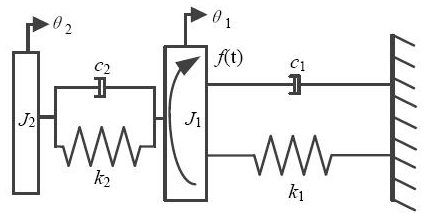
According to Fig. 1, the dynamic equations of the torsional vibration system can be obtained:
where J1 and J2 are the inertia of the main system and the dynamic inertia of the torsional vibration absorber, respectively; θ1 and θ2 are the torsional angular displacements of the main system and the torsional vibration absorber, respectively; k1 and k2 are the torsional stiffness of the main system and the torsional vibration absorber, respectively; c1 and c2 are the torsional damping of the main system and the torsional vibration absorber, respectively; f(t) is the external excitation torque, and ω is the frequency of the external excitation.
2.2 Modal analysis
Assume that the torsional stiffness of the torsional vibration absorber k2 is fixed, 15 000 N m rad−1; the torsional vibration absorber is passive, while the torsional stiffness of the main system k2 is 18 000 N m rad−1; J1 and J2 are 3.0 and 0.3 kg m2, respectively; c1 and c2 are 2.0 and 10.0 N m s rad−1, respectively; The natural frequencies and corresponding damping ratios of the system can be obtained, as shown in Table 1.
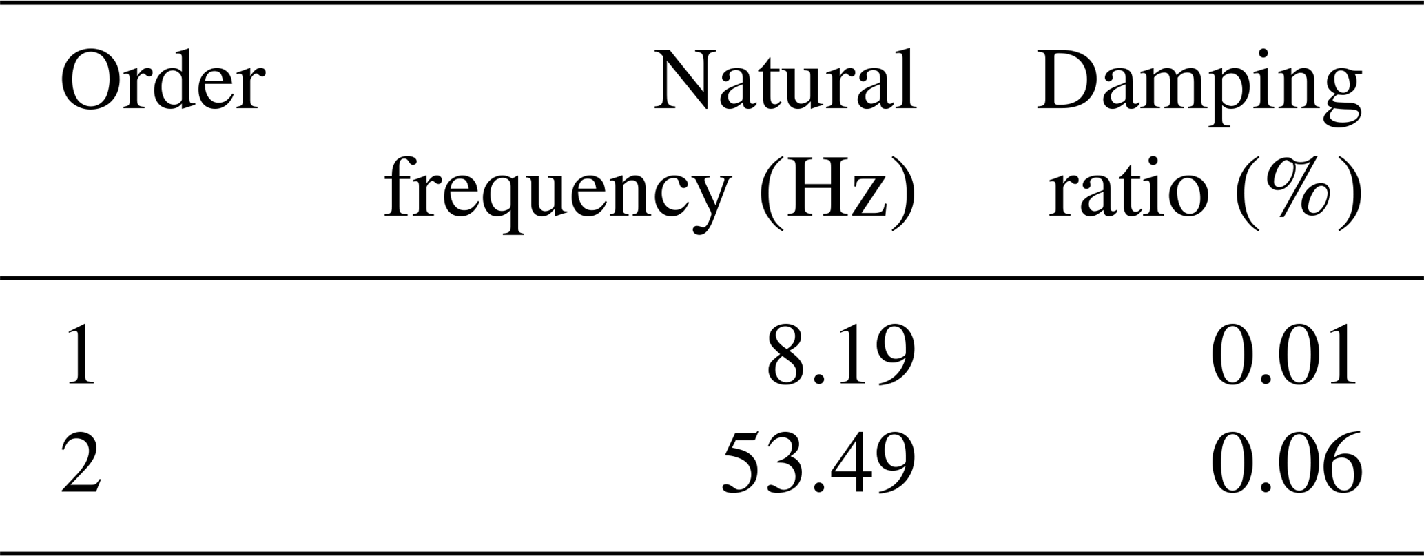
The modal shapes of each natural frequency of the system are shown in Fig. 2.
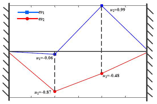
Table 1 and Fig. 2 show that the torsional vibration absorber has a considerable influence on the natural vibration characteristics of the main system, and the modal analysis of the torsional vibration absorber lays a worthy foundation for the new MRE torsional vibration absorber.
2.3 Frequency-tracking scheme of the variable stiffness torsional vibration absorber
Presume that the torsional stiffness of the torsional vibration absorber k2 is variable: then the torsional vibration absorber is a semi-active absorber, and hence the frequency-tracking scheme of the semi-active absorber can be obtained from the following equations.
The Fourier transform is applied to Eqs. (1) and (2):
where F(ω), Θ1(ω), and Θ2(ω) are the Fourier transform expressions of f(t), θ1(t), and θ2(t), respectively.
Solving the above equations, the torsional angular displacements of the main system and the torsional vibration absorber are acquired:
Based on Eq. (4), with the aim of reducing the vibration displacement of the main system to null, the following equation must be satisfied:
assuming that the damping of the torsional vibration absorber is neglected, that is, c2=0. As demonstrated in Eq. (5), if the vibration displacement of the main system needed to be null, the natural frequency of the torsional vibration absorber ought to be equal to the frequency of external excitation torque, . Therefore, k2=J2ω2 is usually used as the frequency-tracking scheme of the semi-active absorber, which is also considered to be the basis of the control strategy of the semi-active torsional vibration absorber in engineering applications.
2.4 Damping effect of semi-active absorber
Assuming the static angular displacement of the main system is , the ratio of the dynamic inertia of the vibration absorber to the inertia of the main system is . The natural frequency ratio of the vibration absorber to the main system is derived as . The ratio of the external excitation frequency to the natural frequency of the main system can be written as ; the damping ratio of the vibration absorber is represented as . The dynamic amplification factor of the main system is
The dynamic amplification factor can represent the vibration-reduction effect of the vibration absorber. The parameters of the semi-active absorber can be set as μ=0.25, b=1, and r=1. The dynamic amplification factors with different absorber damping factors are shown in Fig. 3.
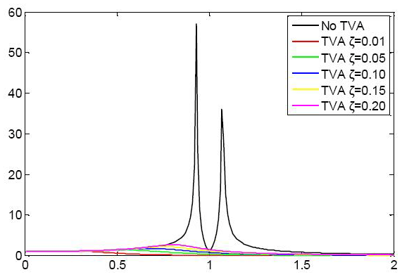
From Fig. 3, it can be observed that when the absorber damping factor increases from 0.01 to 0.20, the damping factors have an insignificant effect on the vibration-reduction performance of the frequency adaptive tuned vibration absorber.
3.1 Mechanical structure design
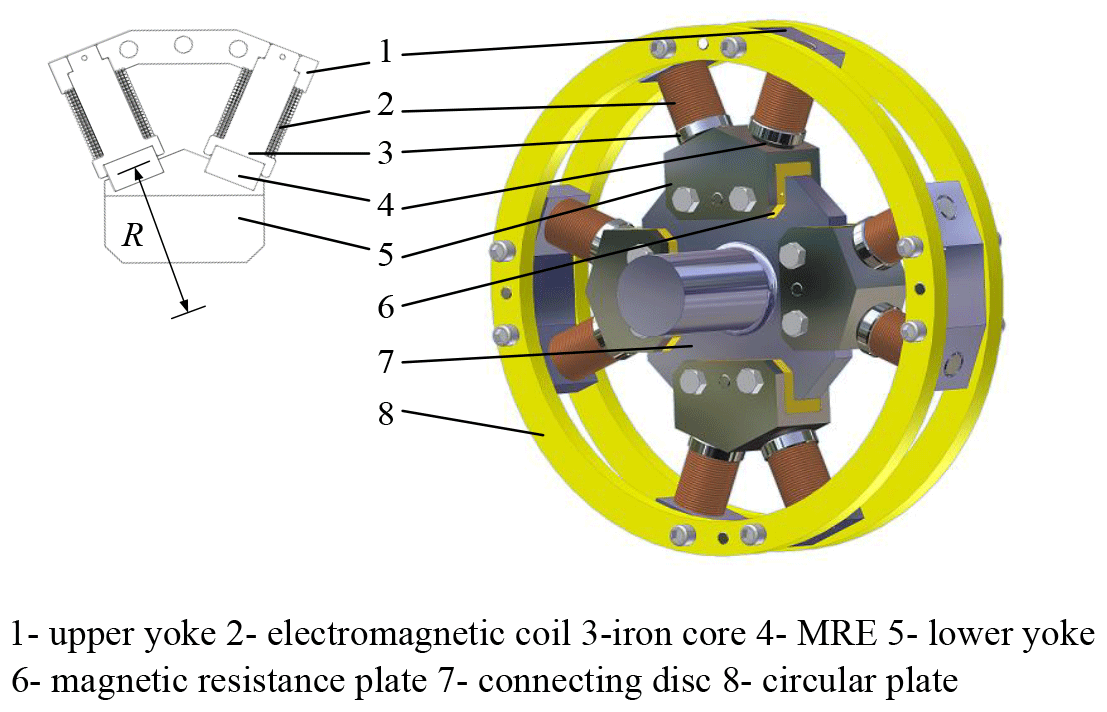
An innovative MRE variable stiffness torsional vibration absorber is designed, as shown in Fig. 4. The new torsional vibration absorber is installed in a proper position of the power transmission path in the form of a coupling. It rotates with the transmission shaft, and the outer contour of the vibration absorber is a rotationally symmetric ring. The absorber is mainly composed of four fan-shaped magnetorheological vibration-absorbing structures. The fan-shaped vibration-absorbing structure consists of an upper yoke (1), two electromagnetic coils (2), two iron cores (3), two MREs (4), and a lower yoke (5), forming a closed magnetic circuit. The electromagnetic coil (2) is installed on the upper yoke and connected with the external controller through the conductive slip ring. The circular plate (6) is used to connect the four fan-shaped structures into a ring to make them equivalent to the dynamic inertia from the perspective of the dynamics. A magnetic resistance plate (6) is equipped between the lower yoke (5) and the connecting disc (5), so that the fan-shaped structure is an independent closed magnetic field from the perspective of the magnetics.
The fan-shaped MRE structure has three advantages.
-
Four fan-shaped MRE structures are evenly installed in the main vibration system, which is connected by the circular plate, forming equivalent dynamic inertia with rotary symmetry. This design can efficiently eliminate the centrifugal force and is more efficacious in reducing torsional vibrations.
-
The fan-shaped MRE structure includes double electromagnetic coils, and the MREs are installed on the main magnetic flux path, which can acquire a larger magnetic field with less power consumption.
-
The variable shear stiffness of the MRE can be transformed into the equivalent variable torsional stiffness of the absorber by this fan-shaped structure.
The variable stiffness element of the vibration absorber is MREs (4) and works in the shear mode, as shown in Fig. 5.
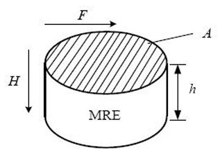
As shown in Fig. 5, F is the shear direction external load; H is the vertical direction external magnetic field; A is the cross-sectional area of the MRE; and h is the thickness of the MRE. In shear working mode, the direction of the external load F is perpendicular to the direction of the external magnetic field H, and the direction of the external magnetic field H is parallel to the forming chain's direction of the MRE ferromagnetic particles (Tesfahunegn et al., 2011).
The MRE is a viscoelastic solid material that has a shear complex modulus, which consists of a storage modulus and a loss modulus:
where G is the complex modulus reflecting the comprehensive shear performance, whereas G′ is the storage modulus reflecting the elastic property of the viscoelastic solid which encounters perceptible alterations in the magnetic field. The alterations of the complex shear modulus with the external magnetic field are close to the storage modulus. G′′ shows that the loss modulus with an insignificant value results in a slight change in the magnetic field that reflects the capacity of dissipating energy. As a result, the storage modulus can characterize the magnetic-induced shear performance of the MRE (Xiang et al., 2018).
The magnetic-induced shear storage modulus of the MRE can be expressed as
where μ0 is the permeability of the vacuum, H0 is the external magnetic field strength, χeff is the effective magnetic susceptibility, and γ is the shear strain.
The relationship between shear modulus and shear stiffness can be obtained from
where kτ is the shear stiffness of the MRE, GH is the magnetic-induced shear modulus, A is the cross-sectional area, and h represents the effective working height.
The U-CAN dynamic test apparatus is mainly used to examine the shear stiffness in the different magnetic field, as shown in Fig. 6. The diameter of the sample is 30 mm, the height is 6 mm, and the whole test speed is set to 10 mm min−1, at room temperature. The shear stiffness of the MREs with different external magnetic fields can be acquired, as indicated in Table 2.
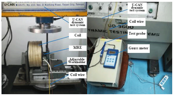
Table 2Shear stiffness with different external magnetic fields.

Referring to the shear working mode, the equivalent torsional stiffness of the new vibration absorber can be achieved:
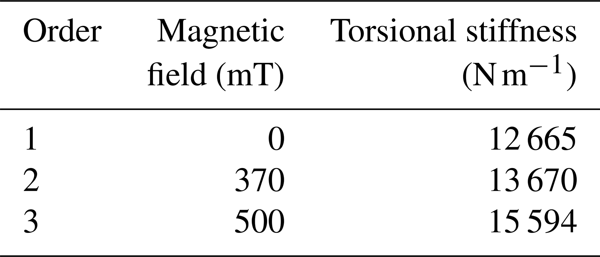
where kA is the equivalent torsional stiffness of the vibration absorber, n is the number of the MREs in the shear mode, n=8, and R is the center distance between the shear working position of the MRE and the torsion center of the vibration absorber, as shown in Fig. 4. The equivalent torsional stiffness of the vibration absorber can be obtained, as shown in Table 3.
Table 3Equivalent torsional stiffness with different external magnetic fields.
In addition to the components in Fig. 4, other components of the vibration absorber also include the speed and torque sensor, controller, a programmable power, and a conductive slip ring. First, the sensors are used to acquire the speed and torque signals. Then, the controller is used to identify the dominant frequency of the external excitation and compute the optimal control current. Next, the current enters the vibration absorber through the conductive slip ring from the programmable power for the purpose of controlling the magnetic field of the electromagnetic coil. Finally, the real-time control of the variable stiffness of the vibration absorber makes its natural frequency effectively follow the dominant frequency of external excitation; the detailed process is shown in Fig. 7.

When the vibration absorber starts working, the electromagnetic coil will produce a changing magnetic field to control the shear stiffness of the MRE in real time, which changes the natural frequency of the vibration absorber; let it track the external excitation dominant frequency. Leading to the resonance of the equivalent dynamic inertia of the vibration absorber results in absorbing the vibration energy of the power transmission path. Aiming for every key vibration frequency band of the power-train system, the variable stiffness torsional vibration absorber can be installed in various positions to suppress the wide frequency band vibration of the system.
3.2 Transient dynamic simulation of the MRE torsional vibration absorber
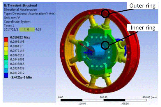
In order to be able to authenticate the consistency of the presented structural design, transient dynamic simulation is utilized to the torsional vibration absorber. The input is loaded with an external torque excitation or a swept frequency (20–60 Hz). The simulation results without a magnetic field are presented in Fig. 8.
The vibration accelerations of the outer ring and inner ring are accumulated, the fluctuating torques can be calculated, and then the signals in the time domain are transformed into the frequency domain, as shown in Fig. 9.
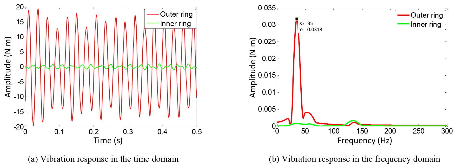
From Fig. 9, it can be noticed that the natural frequency of the MRE torsional vibration absorber without a magnetic field is 35.00 Hz. The above transient dynamic simulation provides an effective reference for the following performance test.
3.3 Magnetic circuit simulation and magnetic field supply analysis
3.3.1 Magnetic field parameters matching for vibration absorbers
The proposed torsional vibration absorber consists of four fan-shaped MRE vibration-absorbing structures. The three-dimensional model and sectional drawing of the fan-shaped MRE vibration absorbing structure are shown in Fig. 10.

The total magnetoresistance of the fan-shaped structure can be calculated by the following formula:
where Rm1, Rm2, Rm3, Rm4, Rm5, and Rm6 are the magnetoresistances of the upper yoke (1), iron core (2), MRE (4), lower yoke (5), MRE (4), and iron core (2), respectively.
The magnetoresistance can be expressed as
where L is the length, μ is the magnetic permeability, and S is the section area of the magnetic field.
Since the magnetic permeability of the MRE is much lower than the iron, the magnetic resistance of the magnetic circuit is mainly caused by MRE (Zhu et al., 2007), and Eq. (11) can be simplified as
In the series magnetic circuit, the magnetic flux across every component is equal in magnitude, and the magnetic potential of the magnetic circuit can be expressed as
where F is the magnetic potential, Φ is the magnetic flux, N is the coil turns, and I is the current of the electromagnetic coil.
Substituting the maximum flux density, magnetic permeability, and physical size of the MRE into the above equations, the coil turns can be obtained, N=400, and the current I is 3 A. Based on the above-mentioned parameters, the MRE can reach its maximum magnetic flux density.
3.3.2 Magnetic circuit simulation analysis
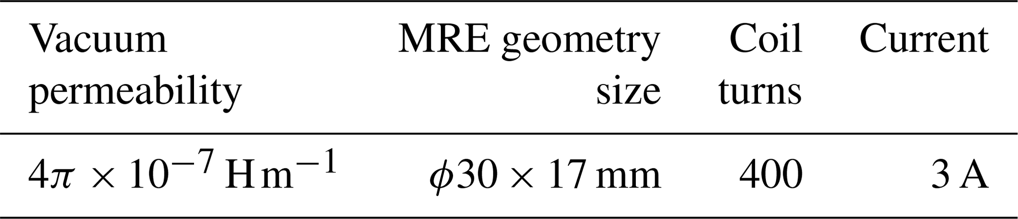
Maxwell software is used to simulate the magnetic circuit of the fan-shaped vibration-absorption structure. Such an approach is utilized to guarantee the closed magnetic circuit and to cover the required magnetic field range of the MRE variable stiffness. The corresponding magnetic circuit simulation parameters are exhibited in Table 4.
The magnetic circuit simulation results of the fan-shaped MRE vibration-absorption structure are shown in Fig. 11.
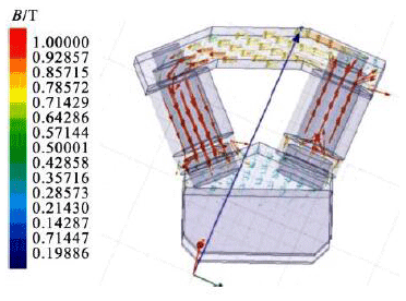

From the simulation results in Fig. 11, it can be concluded that the fan-shaped structure can form a closed magnetic circuit, while if the current of the electromagnetic coil is 3 A, the magnetic flux density passing through the MRE can exceed 500 mT, meeting the required magnetic field range.
By taking into consideration the structural arrangement, magnetic circuit leakage, uncertainty factors, and other ambiguities, the parameters of the fan-shaped MRE vibration-absorption structure can be decisively achieved, as indicated in Table 5.

3.3.3 Principle prototype and magnetic field power supply analysis
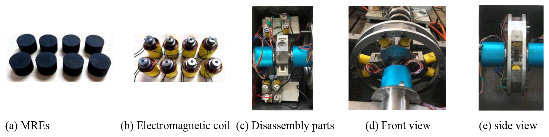
Based on the mechanical structure design in Sect. 3.1, the principle prototype of the vibration absorber is assembled. Figure 12 shows the genuine purpose of the innovative MRE vibration absorber, Fig. 12a shows the MREs, Fig. 12b shows the electromagnetic coil, and Fig. 12c is the overall disassembly parts, Fig. 12d the overall front view, and Fig. 12e the overall side view.
The external programmable power is used to supply power to the fan-shaped structure of the vibration absorber through the conductive slip ring; the actual magnetic field test rig is shown in Fig. 13. The magnetic field near the MRE is 250–300 mT, while in the middle zone close to the magnetic circuit, the magnetic field can reach the required value of 500 mT.
The experimental data establish the rationality of the machine-designed structure of the MRE torsional vibration absorber. Nevertheless, the magnetic supply problem of the rotating electromagnetic coils is effectively solved by using the conductive slip ring.
The torsional vibration absorber utilizes the frequency shift characteristics to preclude the natural vibration frequency from the sensitive vibration frequency band which is generated from external excitations. By such a technique, the reduction of the torsional vibrations of the power-train system can be achieved. It is necessary in addition to assess the dynamic characteristics and confirm the impact of vibration reduction.
4.1 Torsional vibration exciter test rig
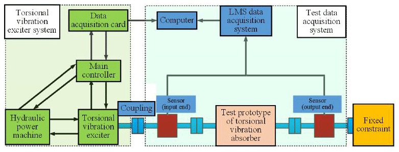
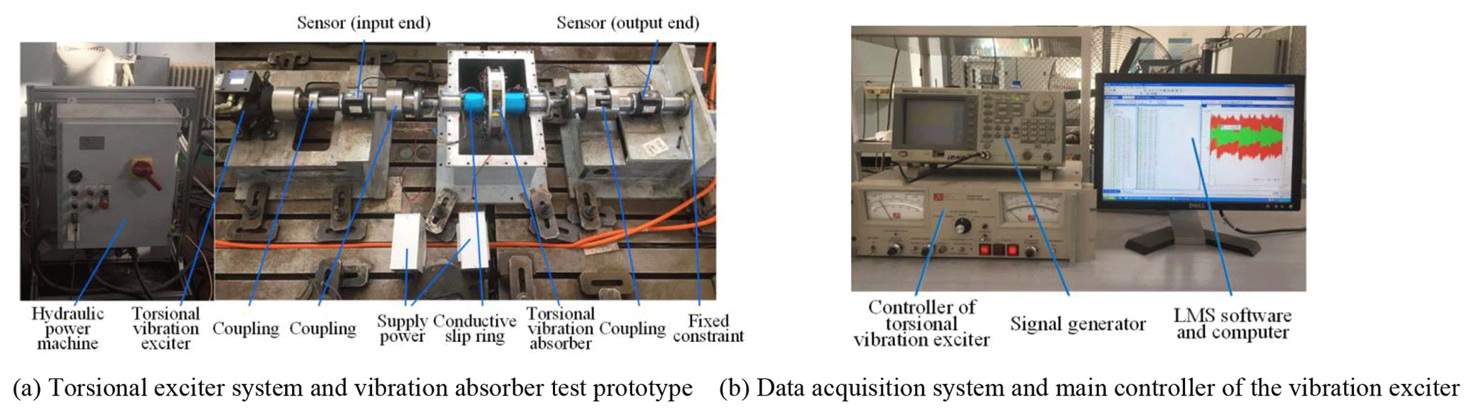
With the intention of evaluating the frequency shift characteristics of the new torsional vibration absorber, a torsional vibration test rig with a torsional vibration exciter operating as the power source is built, as elucidated in Fig. 14. Figure 15 is a realistic photo of the device being used.
The torsional vibration exciter is manufactured by the XCITE company. The signal acquisition system is produced by the LMS company, and the LMS.test.lab software is employed with the purpose of compiling and post-processing the vibration response signal.
In the beginning, the hydraulic pressure pump starts to make sure that the pressure of the torsional exciter reaches 3000 Psi. Then, the LMS.test.lab software is programmed as follows: the sampling frequency is 12 800 Hz and the data acquisition time under sweep frequency excitation is 250 s. After that, the sweep frequency range of the torsional exciter is set to 5–80 Hz, and the vibration amplitude is 36 N m.
4.2 Comparative experiment of vibration-reduction performance
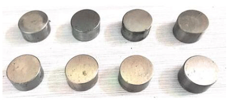
The steel cylinders of the same geometric size as the MRE cylinder are manufactured, as shown in Fig. 16, to be embedded in the fan-shaped structure, replacing the MRE cylinders. Then the outer ring dynamic inertia of the vibration absorber is rigidly connected to the connecting disc.
The sweep frequency excitation experiment is conducted on the test rig. At the outset, the steel and MRE cylinders are installed on the fan-shaped structure individually. Then, the vibration response signals of the input and output ends of the two structures are collected as shown in Fig. 17a and b. Later, these two signals are compared with the vibration response signals of the torsional vibration absorber with the magnetic field 500 mT, as shown in Fig. 17c.
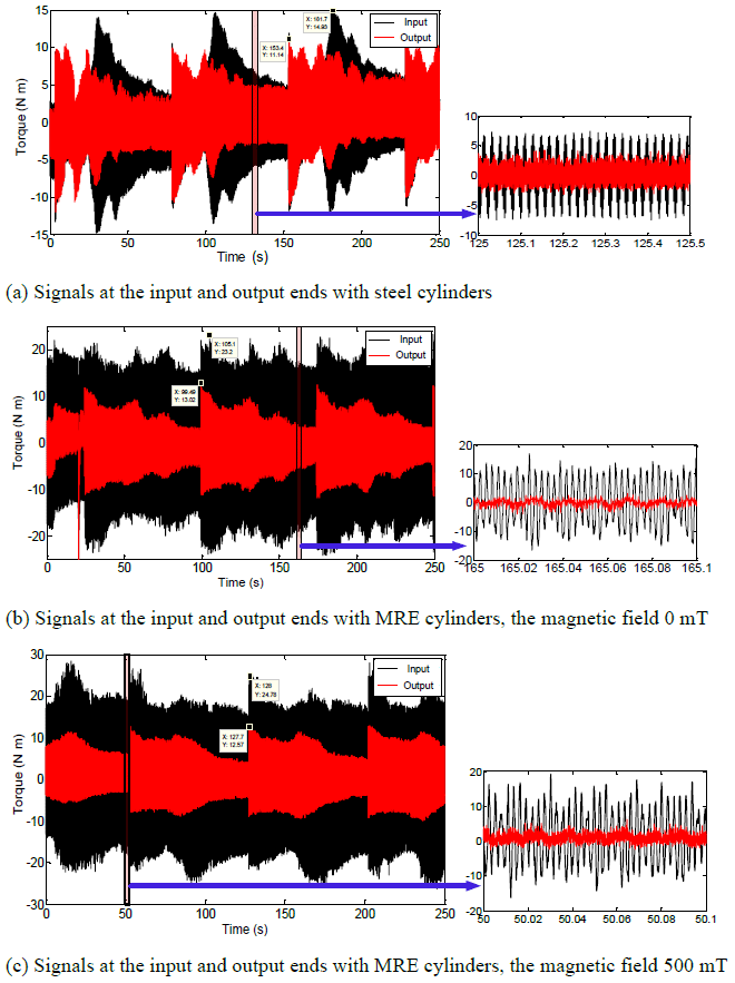
It can be observed from Fig. 17a that the vibration response signals at the input and output terminals of the steel rigid structure are different. The vibration response amplitude decreases from the initial value of 14.93 to 11.14 N m after passing through the steel rigid structure, where the vibration amplitude decreases by 25.39 %. In some frequency bands, the system tends to vibrate in a deterioration manner, which is due to additional inertia added to the test system. It can be noticed from Fig. 17b and c that after the vibration passes through the vibration absorber with MRE cylinders, the magnetic field is null. The vibration response amplitude decreases from 23.20 to 13.02 N m, attaining a 43.88 % reduction.
Once the magnetic field is 500 mT, the vibration response amplitude decreases from 24.78 to 12.57 N m, achieving 49.27 % vibration amplitude reduction. Hence, it can be concluded that the vibration-reduction effect of the torsional vibration absorber with MRE cylinders can acquire a preferable vibration-reduction level than the steel rigid structure in the entire frequency range. The aforementioned outcomes authenticate the excellence of the vibration-reduction effect of the proposed MRE cylinder vibration absorber.
In order to precisely investigate the frequency shift characteristics of the proposed MRE vibration absorber, the vibration response signals at the output in the time domain of Fig. 17 are converted into the frequency domain; subsequently, the natural frequencies of the three structures can be obtained, as shown in Fig. 18.
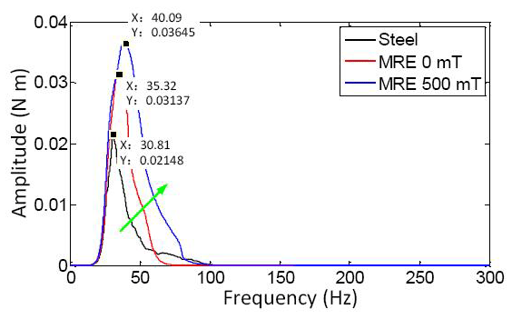
It can be ascertained from Fig. 18 that the natural frequency of the steel rigid structure with steel cylinders is 30.81 Hz when the external magnetic field is null, while the natural frequency of the structure with MRE cylinders is 35.32 Hz, which is consistent with the simulation result in Fig. 9. On the other hand, when the external magnetic field is 500 mT, the natural frequency of the structure with MRE cylinders is 40.09 Hz.
Compared to the steel rigid structure, the natural frequency of the MRE structure moves backward by 14.64 %; in addition, compared with the external magnetic field being null, the natural frequency of the MRE structure with a magnetic field of 500 mT moves backward by 13.51 %. These comparative results demonstrate that the frequency shift phenomenon of the proposed vibration absorber is palpable and tangible, particularly when the absorber works under a 500 mT magnetic field.
Above and beyond, it became apparent that the amplitude of the natural frequencies increases with different structures and by the magnetic field increasing, for the reason that the input excitations are dissimilar. In addition, the input excitation of the MRE structure with a magnetic field of 500 mT exceeds the other two conditions; hence, the comparison of the amplitudes is worthless. The vibration-reduction amplitudes are crucial, the three conditions are 25.39 %, 43.88 %, and 49.27 %, and the MRE structure with a magnetic field of 500 mT has a better vibration-reduction performance.
The comparison of the vibration response signals in the time domain validates the quality of the vibration-reduction performance of the proposed vibration absorber. The comparison between the vibration response signals in the frequency domain attests to the superiority of the new MRE torsional vibration absorber in the field of the frequency shift characteristics.
-
A new type of MRE torsional vibration absorber is devised. The modal analysis, the frequency-tracking scheme, and the damping effect are intensely studied.
-
A transient dynamic simulation is carried out to validate the rationality of the machine structure. The magnetic field parameters have been reasonably designed. Moreover, the magnetic circuit simulation analysis and the magnetic field supply analysis have been performed to substantiate the intellectual of the basic mechanical structure design of the innovative vibration absorber.
-
A special vibration test rig with a torsional vibration exciter has been built so as to assess the frequency shift characteristics of the torsional direction vibration absorber. Additionally, a comparison of the vibration-reduction amplitudes demonstrates its outstanding vibration-reduction performance.
All the data and code are shown in the paper.
PG and HL designed the new torsional vibration absorber; PG and PY proposed the research methods; PG and HL carried out the experiments; PG, HL and CX analysed experimental results. PG, PY and TM wrote the manuscript.
The authors declare that they have no conflict of interest.
This article is part of the special issue “Robotics and advanced manufacturing”. It is not associated with a conference.
This work was supported by the China Postdoctoral Science Foundation (grant no. 2020M680368), the Natural Science Foundation of Chongqing, China (grant no. cstc2020jcyj-msxmX1081), VTDP, and the National Natural Science Foundation of China (grant no. 51775040).
This paper was edited by Haiyang Li and reviewed by three anonymous referees.
Albanese, A. M. and Cunefare, K. A.: The temporal and spatial effects of a magnetorheological elastomer in squeeze mode, J. Acoust. Soc. Am., 114, 2419–2419, 2003a.
Albanese, A. M. and Cunefare, K. A.: Properties of a magnetorheological semi-active vibration absorber. Smart Structures and Materials 2003: Damping and Isolation, Int. Soc. Opt. Photon., 5052, 36–44, 2003b.
Chen, J. R.: Automobile Structure, China Machine Press, Beijing, 2005.
Couderc, P., Callenaere, J., Hagopian, J. D., Ferraris, G., Kassai, A., Borjesson, Y., Verdillon, L., and Gaimard, S.: Vehicle driveline dynamic behaviour: experimentation and simulation, J. Sound Vib., 218, 133–157, 1998.
Crowther, A. R.: Transient vibration in powertrain systems with automatic transmissions, PhD thesis, University of Technology Sydney, Sydney, 2004.
Deng, H. X. and Gong, X. L.: Adaptive tuned vibration absorber based on magnetorheological elastomer, J. Intell. Mater. Syst. Struct., 18, 1205–1210, 2007.
Dong, X., Li, W., Yu, J., Pan, C., and Wang, X.: Magneto–Rheological Variable Stiffness and Damping Torsional Vibration Control of Powertrain System, Front. Mater., 7, 121, https://doi.org/10.3389/fmats.2020.00121, 2020.
Gao, P., Walker, P. D., Liu, H., Zhou, S., and Xiang, C.: Application of an adaptive tuned vibration absorber on a dual lay-shaft dual clutch transmission powertrain for vibration reduction, Mech. Syst. Signal Process., 121, 725–744, 2019a.
Gao, P., Xiang, C., Liu, H., Walker, P., and Zhang, N.: Design of the frequency tuning scheme for a semi-active vibration absorber, Mech. Mach. Theory, 140, 641–653, 2019b.
Ginder, J. M., Schlotter, W. F., and Nichols, M. E.: Magnetorheological elastomers in tunable vibration absorbers. Smart structures and materials 2001: damping and isolation, Int. Soc. Opt. Photon., 4331, 103–111, 2001.
Hoang, N.: An adaptive tunable vibration absorber using magnetorheological elastomers for vibration control of vehicle powertrains, PhD thesis, University of Technology Sydney, Sydney, 2011.
Hoang, N., Zhang, N., and Du, H.: A dynamic absorber with a soft magnetorheological elastomer for powertrain vibration suppression, Smart Mater. Struct., 18, 074009, https://doi.org/10.1088/0964-1726/18/7/074009, 2009.
Lerner, A. A. and Cunefare, K. A.: Performance of MRE-based vibration absorbers, J. Intell. Mater. Syst. Struct., 19, 551–563, 2008.
Li, S. T.: Effects of machining errors, assembly errors and tooth modifications on loading capacity, load-sharing ratio and transmission error of a pair of spur gears, Mech. Mach. Theory, 42, 698–726, 2007.
Liu, H.: Torsional vibration dynamic simulation and analysis of vehicle powertrain, PhD thesis, Beijing Institute of Technology, Beijing, 2003.
Liu, H., Zhang, C., Xiang, C. L., and Wang, C.: Tooth profile modification based on lateral-torsional-rocking coupled nonlinear dynamic model of gear system, Mech. Mach. Theory, 105, 606–619, 2016.
Liu, H., Wang, X., and Liu, F.: Stiffness and vibration isolation characteristics of a torsional isolator with negative stiffness structure, J. Vibroengineering, 20, 401–416, 2018.
Londhe, A. and Yadav, V. H.: Design and optimization of crankshaft torsional vibration damper for a 4-cylinder 4-stroke engine, SAE Technical Paper, https://doi.org/10.4271/2008-01-1213, 2008.
Nagar, A., Chokkalingam, V., Umashankar, N., and Shankar, S. R.: Improvement in crank train torsional vibration (TV) performance of multi-cylinder diesel engine, SAE Technical Paper, https://doi.org/10.4271/2013-01-2777, 2013.
Nguyen, X. B., Komatsuzaki, T., and Truong, H. T.: Novel semiactive suspension using a magnetorheological elastomer (MRE)-based absorber and adaptive neural network controller for systems with input constraints, Mech. Sci., 11, 465–479, https://doi.org/10.5194/ms-11-465-2020, 2020.
Ni, Z. C., Gong, X. L., Li, J. F., and Chen, L.: Study on a dynamic stiffness-tuning absorber with squeeze-strain enhanced magnetorheological elastomer, J. Intell. Mater. Syst. Struct., 20, 1195–1202, 2009.
Parag, W. and Ahmet, K.: Influence of Tooth Profile Modification on Helical Gear Durability, J. Mech. Des., 124, 501–510, 2002.
Qian, L. J., Xin, F. L., Bai, X. X., and Wereley, N. M.: State observation based control algorithm for magnetorheological elastomer dynamic vibration absorbing systems: principle and analysis, J. Intell. Mater. Syst. Struct., 28, 2539–2556, 2017.
Rao, Z., Gong, X., Na, T., Qin, C., and Yang, Z.: Design and analyses of axial semi-active dynamic vibration absorbers based on magnetorheological elastomers, J. Intell. Mater. Syst. Struct., 25, 2199–2207, 2014.
Shangguan, W. B., Guo, Y., Wei, Y., Rakheja, S., and Zhu, W.: Experimental Characterizations and Estimation of the Natural Frequency of Nonlinear Rubber-Damped Torsional Vibration Absorbers, J. Vib. Acoust., 138, 051006, https://doi.org/10.1115/1.4033579, 2016.
Shi, H. F., Yu, M., Zhu, M., Fu, J., Choi, S. B., and Xing, Z. W.: An investigation of the dynamic behaviors of an MRE isolator subjected to constant and alternating currents, Smart Mater. Struct., 25, 077002, https://doi.org/10.1088/0964-1726/25/7/077002, 2016.
Shi, W. K., Long, Y., and Lu, Y.: Study on multistage non-linear dual mass flywheel damper, J. Vib. Shock, 28, 92–96, 2009.
Song, L., Li, L., Yin, Y., Luo, S., and Fan, Z.: Study on design theory of dual mass flywheel based on shape constraint, J. Mech. Eng., 4801, 111–118, 2012.
Tesfahunegn, Y. A., Rosa, F., and Gorla, C.: The effects of the shape of tooth profile modifications on the transmission error, bending, and contact stress of spur gears, J. Mech. Eng. Sci., 224, 1749–1758, 2011.
Xiang, C. and Geng, C.: Analysis and calculation on dynamic characteristics of Geislinger coupling, J. Mach. Des., 21, 24–26, 2004.
Xiang, C., Gao, P., Liu, H., and Zhou, H.: Experimental and theoretical study of temperature-dependent variable stiffness of magnetorheological elastomers, Int. J. Mater. Res., 109, 113–128, 2018.
Xin, F. L., Bai, X. X., and Qian, L. J.: Principle, modeling, and control of a magnetorheological elastomer dynamic vibration absorber for powertrain mount systems of automobiles, J. Intell. Mater. Syst. Struct., 28, 2239–2254, 2017.
Yu, M., Yan, X., and Mao, L.: A new smart material with controllable stiffness and damping magnetorheological elastomer, Mater. Rev., 7, 030, https://doi.org/10.2514/1.26230, 2007.
Zhang, N., Crowther, A., Liu, D. K., and Jeyakumaran, J.: A finite element method for the dynamic analysis of automatic transmission gear shifting with a four-degree-of-freedom planetary gearset element, Proc. Inst. Mech. Eng. D, 217, 461–473, 2003.
Zhu, Y., Gong, X., and Zhang, P.: Simulation on physical parameters of magneto-rheological elastomers, Chin. J. Comput. Mech., 5, 565–570, 2007.
- Abstract
- Introduction
- Torsional vibration-absorption principle
- Structural design of torsional vibration absorber
- Frequency shift characteristics and vibration-reduction performance assessment
- Conclusions
- Code and data availability
- Author contributions
- Competing interests
- Special issue statement
- Financial support
- Review statement
- References