the Creative Commons Attribution 4.0 License.
the Creative Commons Attribution 4.0 License.
 | 27 Jan 2021
Analysis of influence factors of rail corrugation in small radius curve track
Zhiqiang Wang
Zhenyu Lei
In order to effectively prevent and control the generation and development of rail corrugation, according to the actual line condition of the small radius curve section, the vehicle (with flexible wheel sets)–track space coupled model was established by using the multi-body dynamic software UM (Universal Mechanism), which could consider the coupled relationship in three directions of space, and the dynamic analysis for the corrugation section was carried out by using the model. Then, based on the theory of friction self-excited vibration, the three-dimensional model of a wheel–rail system was established by using the finite-element software ABAQUS, and the complex eigenvalue analysis of influence factors of rail corrugation was conducted based on wheel–rail contact parameters obtained by dynamic calculation. Through the stability analysis of the wheel–rail system with different fastener vertical and lateral stiffnesses, friction coefficients, and superelevation states, we find that properly increasing the fastener vertical and lateral stiffnesses, controlling the wheel–rail friction coefficient below 0.4, and keeping the balanced superelevation state of the track structure can effectively reduce the occurrence possibility of unstable vibration of the wheel–rail system, thus inhibiting the generation and development of rail corrugation. The excess superelevation state of the track structure results in the unstable friction self-excited vibration of the wheel–rail system at the inner wheel–inner rail, while the deficient superelevation state results in the unstable friction self-excited vibration of the wheel–rail system at the outer wheel–outer rail, which shows that the superelevation state of the track structure directly affects the formation of rail corrugation and determines the development order of corrugation of inner and outer rails. This conclusion can well explain the cause of corrugation appearing on only one side rail.
- Article
(2006 KB) - Full-text XML
- BibTeX
- EndNote


Rail corrugation is a common damage of track structures that is characterized by periodic irregularities on the surface of the rail head. Due to the use of wear-type wheel tread and a large radius curve track, rail corrugation is rarely found on the main-line railway, but for metro lines, rail corrugation is more universal, especially in the small radius curve section: rail corrugation not only appears early, but also develops rapidly. The wavelength range of rail corrugation is generally 20–300 mm, and the wave depth is not more than 1 mm (Li, 2015). The existence of corrugation will aggravate the vibration of vehicle and track components and produce wheel–rail high-frequency noise, which not only affects the safety and stability of train operation, but also has a certain negative effect on the surrounding living environment.
In order to control the generation and development of rail corrugation effectively, a large number of experts and scholars have studied the formation mechanism and development characteristics of rail corrugation combined with experimental tests and theoretical analysis. Oostermeijer (2008) summarized occurrence causes, research progress, and corresponding treatment measures of rail corrugation in railway systems around the world and pointed out that rail materials, rail support types, rail surface initial irregularities, and track slab stiffness have an impact on rail corrugation. Saulot et al. (2006) studied the influence of the wheel–rail friction on rail corrugation from the perspective of rail metallurgic properties and found that the continuous accumulation of rail deformation eventually led to corrugation. Kurzeck (2011) found that the vibration frequency of P2 force was close to the first-order bending frequency of the wheel set through the numerical investigation and considered that lateral creep and a high wheel–rail friction coefficient would lead to friction self-excited vibration of the wheel–rail system in small radius curve lines and result in rail corrugation. By establishing the numerical model of rail corrugation, Meehan et al. (2016) found that increasing the discreteness of train running speed can effectively reduce the growth rate of corrugation. When the discreteness of train running speed was small, the growth of rail corrugation was obviously accelerated. Using the Kalker variational method, assuming that the wear amount was proportional to the friction power, Xie and Iwnicki (2008) established a three-dimensional non-Hertz, non-stationary wheel–rail rolling contact model. Based on this model, it was found that there was a fixed phase shift between wear and normal force when wheel–rail non-Hertz contact was used, which indicated that the initial irregularity of any wavelength might continue to develop. Jin's team (Jin et al., 2004, 2006; Jin and Wen, 2007; Wen et al., 2008; Li et al., 2016) established a complete wheel–rail coupled calculation model including wheel–rail coupling, wheel–rail contact, and rail wear and proposed a plastic-flow rail corrugation calculation model, which supplemented the generation mechanism of rail corrugation caused by initial irregularities. Zhang et al. (2013, 2015) carried out many field investigations, experimental tests, and theoretical studies on the phenomenon of abnormal rail corrugation in the Beijing subway and found that the installation of shear-type damper fasteners would lead to the low damping of the track structure, which made the rail prone to unstable vibration and formation of corrugation eventually. Meanwhile, a set of corrugation detection and evaluation methods was proposed accordingly. Chen's team (Cui et al., 2017, 2018; Zhao et al., 2018; Yan et al., 2018) proposed the theory of rail corrugation caused by the friction self-excited vibration of the wheel–rail system under saturated creep force. Moreover, the influence of different parameters on the friction self-excited vibration of the wheel–rail system was analyzed, and some relevant suggestions were put forward.
To sum up, the causes of rail corrugation are complex and numerous, and there is no complete theoretical system that can explain all the rail corrugation phenomena well. Therefore, when studying the forming mechanism and influence factors of rail corrugation in small radius curve sections, it is necessary to take line conditions of rail corrugation sections into comprehensive consideration and apply numerical simulation methods to analyze the phenomenon of rail corrugation.
This paper carries out a parametric study to investigate possible practical solutions to reduce the occurrence of rail corrugation instead of identifying root causes or describing development characteristics of corrugation. With that in mind, a successful deliverable of this study will be some practical activities or products that can increase the railway maintenance intervals, especially rail-grinding intervals. First, the vehicle (with flexible wheel sets)–track space coupled model, which can consider the coupled relationship in three directions of space, is established by using the multi-body dynamic software UM (Universal Mechanism) according to the actual line situation in the small radius curve section, and the dynamic analysis of the corrugation section is carried out by using this model. Then, based on the friction self-excited vibration theory, the three-dimensional model of the wheel–rail system is established by using the finite-element software ABAQUS, and the complex eigenvalue analysis of influence factors of rail corrugation is conducted by using the wheel–rail contact parameters obtained by dynamic calculation so as to provide guidance for the prevention and control of rail corrugation.
2.1 Vehicle model
The multi-body dynamic software UM is used to establish a single-section vehicle model, including three types of mass bodies, vehicle body, bogies, and wheel sets, in which the vehicle body and bogies are rigid bodies and wheel sets are flexible bodies, with masses and moments of inertia taken into account. The vehicle body and bogies, bogies and wheel sets are all connected by spring-damper elements to simulate primary and secondary suspension components, with stiffness and damping in three directions. Refer to the literatures (Lei et al., 2019; Lei and Wang, 2020) for the parameter values of the vehicle model.
2.2 Track model
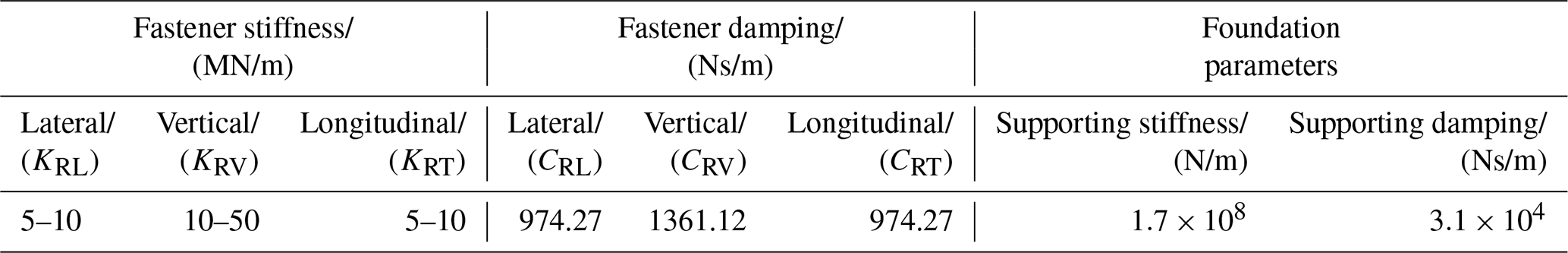
The track model adopts the flexible track model, and the rail is simulated as a Timoshenko beam considering the shear deformation, which can better reflect the effect of high-frequency vibration and is suitable for the research of rail corrugation (Sun et al., 2018). The Bushing force elements are used to simulate fasteners (Lei and Wang, 2020). The three-dimensional solid-element model of the slab is established by the finite-element software ABAQUS and imported into the UM program as a subsystem of the dynamic model. The cross-section size of the slab is 2700 mm × 300 mm, and the length is 60 m. The connection between slab and foundation and the connection between slab and rails are all simulated by Bushing force elements, which can consider the stiffness and damping in three directions. See Table 1 for fastener parameters and grounding parameters of the slab (Li, 2012).
2.3 Wheel–rail contact model
The Kik–Piotrowski contact model (Piotrowski and Kik, 2008) is used to simulate the wheel–rail contact relationship. The model assumes that the normal contact stress along the wheel rolling direction is a semi-elliptical distribution, and the contact area is obtained by the virtual penetration principle between wheel and rail. The normal contact stress can be obtained by geometric points in the contact area satisfying contact conditions, and the tangential contact problem can be solved by the improved FASTSIM algorithm. The model has the characteristics of fast calculation speed and high reliability.
Based on the above vehicle model, track model, and wheel–rail contact model, the vehicle–track space coupled dynamic model is established, and the model schematic diagram is shown in Fig. 1. Refer to the literatures (Lei et al., 2019; Lei and Wang, 2020) for the model validation.

3.1 Wheel–rail system model
In the urban rail transit, especially metro lines, the concrete monolithic track slab is widely used at present. On the premise of not affecting the model to reflect the actual structure, the wheel–rail system is simplified appropriately in this paper. The finite-element model of the wheel–rail system established in the paper is shown in Fig. 2a, which is composed of a wheel set, two rails, and a slab. The fasteners were simulated by means of spring-damper elements to realize the connection between rails and slab. The wheel–rail contact geometry relationships are shown in Fig. 2b–d, where W is the wheel weight, NL is the normal force between outer wheel and outer rail, NR is the normal force between inner wheel and inner rail, δL is the contact angle between outer wheel and outer rail, δR is the contact angle between inner wheel and inner rail, FL is the lateral creep force of the outside wheel–rail contact patch, and FR is the lateral creep force of the inside wheel–rail contact patch; CRL, CRV, and CRT are lateral, vertical, and longitudinal dampings of fasteners, respectively; KRL, KRV, and KRT are lateral, vertical, and longitudinal stiffnesses of fasteners, respectively; KS and CS are the foundation-supporting stiffness and foundation-supporting damping, respectively.
The multi-body dynamic software UM is used to simulate a vehicle passing through the small radius curve section. It can be known that when the vehicle passes through the small radius curve track with the curve radius less than 350 m, the creep forces generated on inner and outer rails are all saturated; that is, the creep forces are equal to the friction forces in these cases (Cui et al., 2019). The motion equation of the wheel–rail system established in this paper can be written as follows (Li, 2017):
where M, C, and K represent the mass matrix, damping matrix, and stiffness matrix of the wheel–rail system, respectively; , , and u represent the acceleration, velocity, and displacement of the wheel–rail system in the inertial coordinate system caused by friction self-excited vibration; F is the external force acting on the wheel–rail system. When the rail has no initial irregularity on the rail surface and no harmonic external force F acting, the coefficient matrices M, C, and K of Eq. (1) are symmetric matrices, so the characteristic equation of Eq. (1) can not have eigenvalues with real parts greater than 0; that is, the motion of the system is stable and will not produce self-excited vibration. When the wheel–rail creep force reaches saturation, there is the following relationship for the friction force:
where f is the friction force; N is the normal force; μf is the dynamic friction coefficient; k is the equivalent spring stiffness of the wheel–rail contact; uwn represents the normal displacement of the wheel at the wheel–rail contact point; urn represents the normal displacement of the rail at the wheel–rail contact point. The friction forces at all nodes of the wheel–rail contact point can be expressed by the matrix form of Eq. (3):
Putting Eq. (3) into Eq. (1), we can find that
where ΔF is the sum of external forces acting on the wheel–rail system. The characteristic equation of Eq. (4) can be written as follows:
where the stiffness matrix (K−Kf) is an asymmetric matrix, and its eigenvalues may have positive real parts. The general form of the solution of Eq. (4) is shown in Eq. (6):
where {ϕi} is the eigenvector; t is the motion time. It can be seen from Eq. (6) that if one or more eigenvalues with positive real parts exist in the motion equation, the wheel–rail system will produce successive self-excited vibration under an impact load even if there is no external harmonic load acting or continuous rail surface irregularity.
Rail corrugation is the result of the joint action of a wavelength-fixed mechanism and a material damage mechanism. Researchers have verified that the passing frequencies of corrugation are the same as characteristic frequencies of wheel–rail friction work (Grassie and Kalousek, 1993; Sato et al., 2002; Oostermeijer, 2008). The literature (Chen et al., 2010) has explained the cause of rail corrugation caused by wheel–rail friction self-excited vibration. Therefore, subsequent research and analysis are mainly based on the theory of friction self-excited vibration of the wheel–rail system, and it is believed that the passing frequency of corrugation is the same as that of friction self-excited vibration of the wheel–rail system.
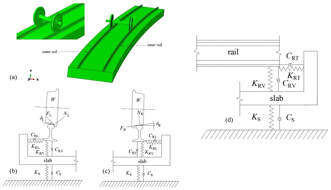
Figure 2Friction self-excited vibration model of the wheel–rail system. (a) Wheel–rail system model. (b) Lateral contact geometry relationship between the outer wheel and outer rail (including the slab). (c) Lateral contact geometry relationship between the inner wheel and inner rail (including the slab). (d) Longitudinal contact geometry relationship between rail and slab.
3.2 Model parameters
The curve radius of the model is 350 m, and the wheel tread is a LM wear-type profile (Chen et al., 2020). The rail and wheel set are made of high-carbon low-alloy steel, and the slab is made of C40 concrete. See Table 2 for material properties of each component. The rail type is 60 kg/m (Chen et al., 2020), rail length is 36 m, and rail cant is 1∕40. The cross-section size of the slab is 2700 mm × 300 mm, and the length is consistent with the rail length. The fastener interval is 0.6 m. The parameter values of connection parts of the track structure are listed in Table 1.

According to the field investigation and considering the feasibility of engineering measures, this section will select different fastener vertical stiffness and lateral stiffness combinations, different friction coefficients, and different superelevation and speed matching relations to analyze influence factors of rail corrugation in the small radius curve section.
4.1 Influence of fastener stiffnesses on wheel–rail system instability
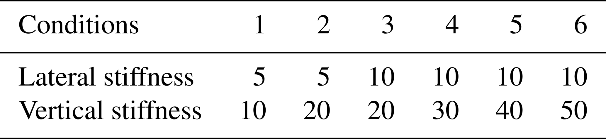
In this section, the complex eigenvalue analysis method is used to analyze the influence of fastener stiffnesses on the friction self-excited vibration of the wheel–rail system, so as to further understand the influence of fastener vertical and lateral stiffnesses on rail corrugation. Based on the field investigation, six working conditions of different vertical stiffness and lateral stiffness combinations of fasteners are set as shown in Table 3 (Li, 2015; Li et al., 2016). Generally, the longitudinal stiffness and lateral stiffness of fasteners are equal, so the longitudinal stiffness and lateral stiffness of fasteners are consistent in the analysis of influence factors (Chen et al., 2010; Li, 2015). The wheel–rail friction coefficient is taken as 0.4 and the superelevation value of the track structure is set as 120 mm.
Table 3Calculation conditions of fastener stiffnesses (unit: MN/m).
According to the theory of friction self-excited vibration, the larger the absolute value of the negative effective damping ratio is, the more likely the wheel–rail system is to produce friction self-excited vibration, which will lead to the further development of rail corrugation; that is, the frequency corresponding to the unstable friction self-excited vibration of the wheel–rail system is the frequency of corrugation occurrence. It is generally considered that the unstable vibration mode corresponding to the frequency at the minimum effective damping ratio is the dominant mode of the wheel–rail system, which has the greatest influence on the wheel–rail system and is most likely to cause rail corrugation. The effective damping ratio ξ is calculated according to Eq. (7) (Chen et al., 2010):
where Re(λ) and Im(λ) are real and imaginary parts of complex eigenvalues of characteristic equations. In the finite-element software ABAQUS, the effective damping ratio of the wheel–rail system can be extracted directly through complex eigenvalue calculations of linear perturbation analysis, and the stability of the wheel–rail system can be predicted. The specific calculation process of the effective damping ratio is shown in Fig. 3.

By using the finite-element model of the wheel–rail system with a curve radius of 350 m, the negative effective damping ratio distributions and corresponding dominant vibration modes under six working conditions shown in Table 3 can be obtained through complex eigenvalue calculations, as shown in Figs. 4–5.
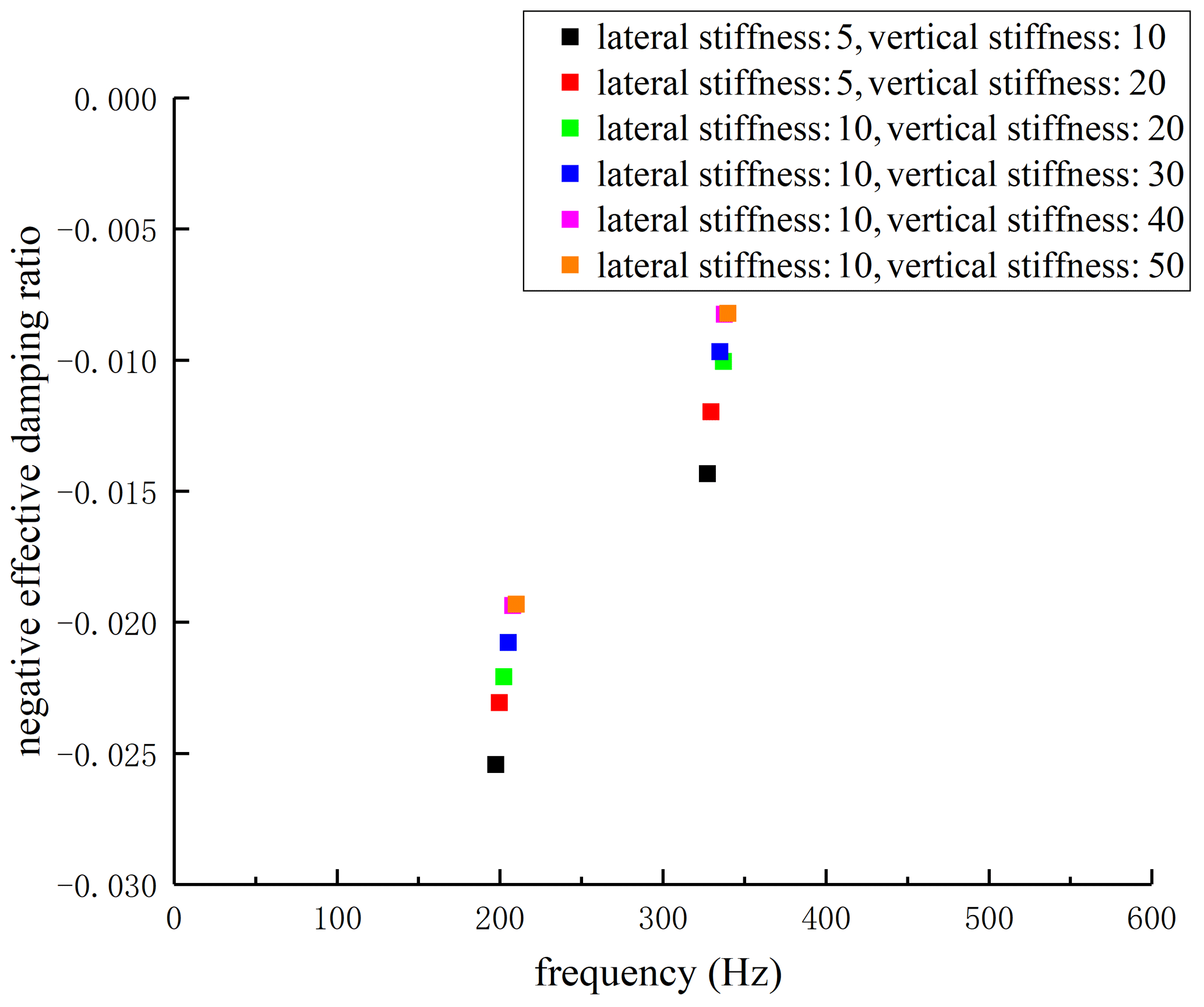
It can be seen from Fig. 4 that the minimum negative effective damping ratios corresponding to six working conditions appear at 197.4, 199.6, 202.3, 205.1, 207.8, and 210.0 Hz, respectively. The average wavelength of rail corrugation measured on-site is about 80 mm, the vehicle speed is 60 km/h, and the corresponding vibration frequency is 208.3 Hz, so the calculated results are in good agreement with the field situation. At the same time, the minimum negative effective damping ratios under six working conditions are −0.02543, −0.02307, −0.02209, −0.02078, −0.01936, and −0.01932, respectively. It can be established that the absolute values of negative effective damping ratios of the whole wheel–rail system will decrease with the increase in vertical and lateral stiffnesses of fasteners, which shows that increasing vertical and lateral stiffnesses of fasteners to a certain extent can significantly inhibit the wheel–rail friction self-excited vibration, thus controlling the generation and development of rail corrugation.

Figure 5Dominant mode diagrams. (a) Lateral stiffness: 5, vertical stiffness: 10. (b) Lateral stiffness: 5, vertical stiffness: 20. (c) Lateral stiffness: 10, vertical stiffness: 20. (d) Lateral stiffness: 10, vertical stiffness: 30. (e) Lateral stiffness: 10, vertical stiffness: 40. (f) Lateral stiffness: 10, vertical stiffness: 50.
In addition, by comparing dominant vibration modes in Fig. 5, it can be found that the unstable vibration corresponding to the minimum negative effective damping ratio of each working condition occurs on the inner wheel–inner rail of the wheel–rail system, which is consistent with the phenomenon that inner-rail corrugation is serious and outer-rail corrugation is slight in the small radius curve track of metro lines.
4.2 Influence of friction coefficients on wheel–rail system instability
The friction coefficient is one of the most important parameters in the wheel–rail contact friction pair. In the actual railway line, the wheel–rail friction coefficient will change with maintenance conditions, dry and wet conditions, and other factors. This section mainly studies the stability of the wheel–rail system under different friction coefficients. Based on the finite-element analysis model of the wheel–rail system, adjust the wheel–rail friction coefficients to 0.2, 0.4, 0.6, and 0.8 by referencing the literatures (Xiao, 2012; Zhang, 2015), take the vertical stiffness of fasteners as 20 MN/m, the lateral stiffness as 10 MN/m, and the superelevation value of the track structure as 120 mm, and conduct the complex eigenvalue analysis of the wheel–rail system. The minimum negative effective damping ratios of the wheel–rail system with different friction coefficients are shown in Fig. 6. It can be concluded that the minimum effective damping ratios under four working conditions are −0.02034, −0.02209, −0.04873, and −0.09085, and the corresponding frequencies are 198.5, 202.3, 208.1, and 211.8 Hz.
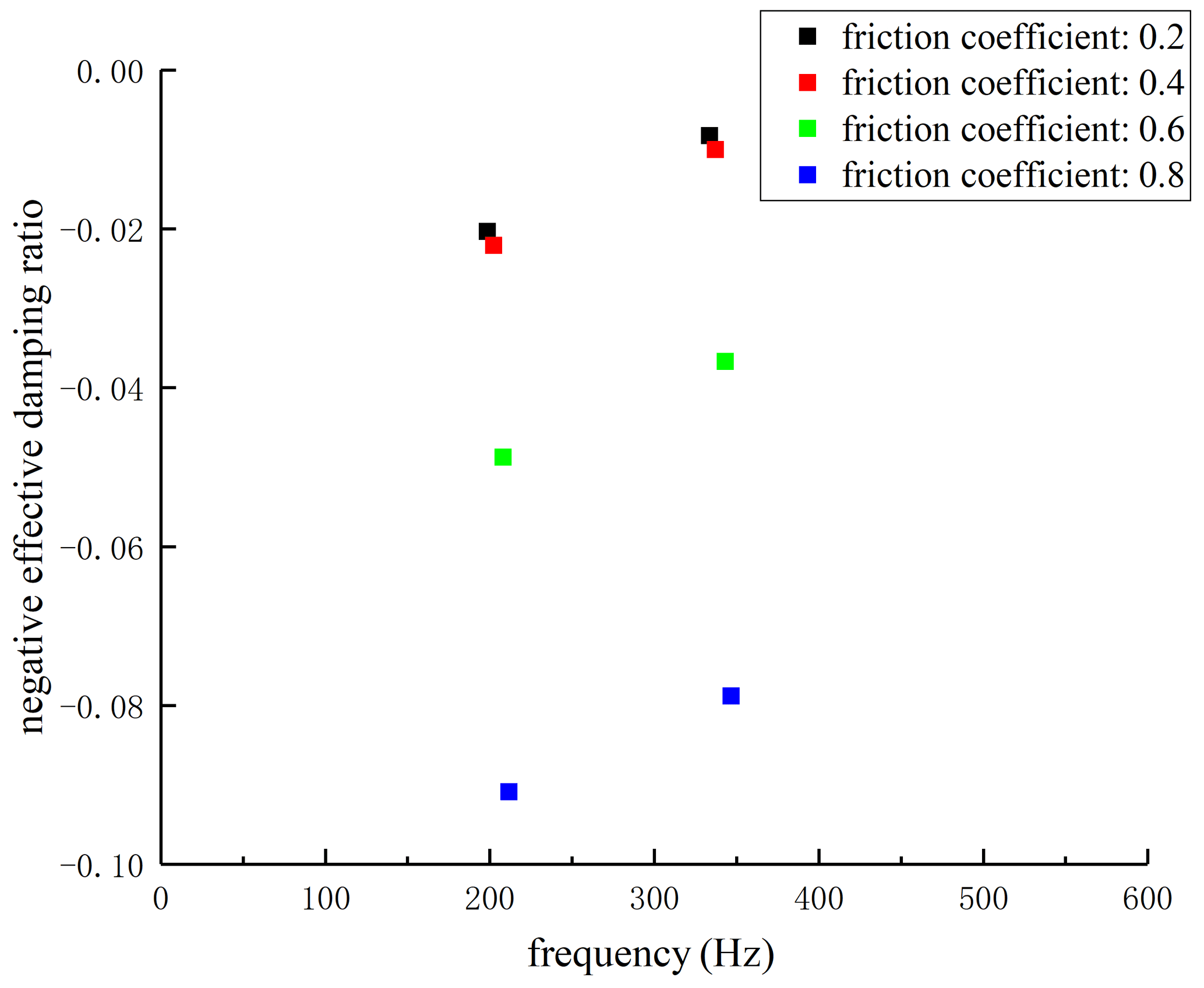
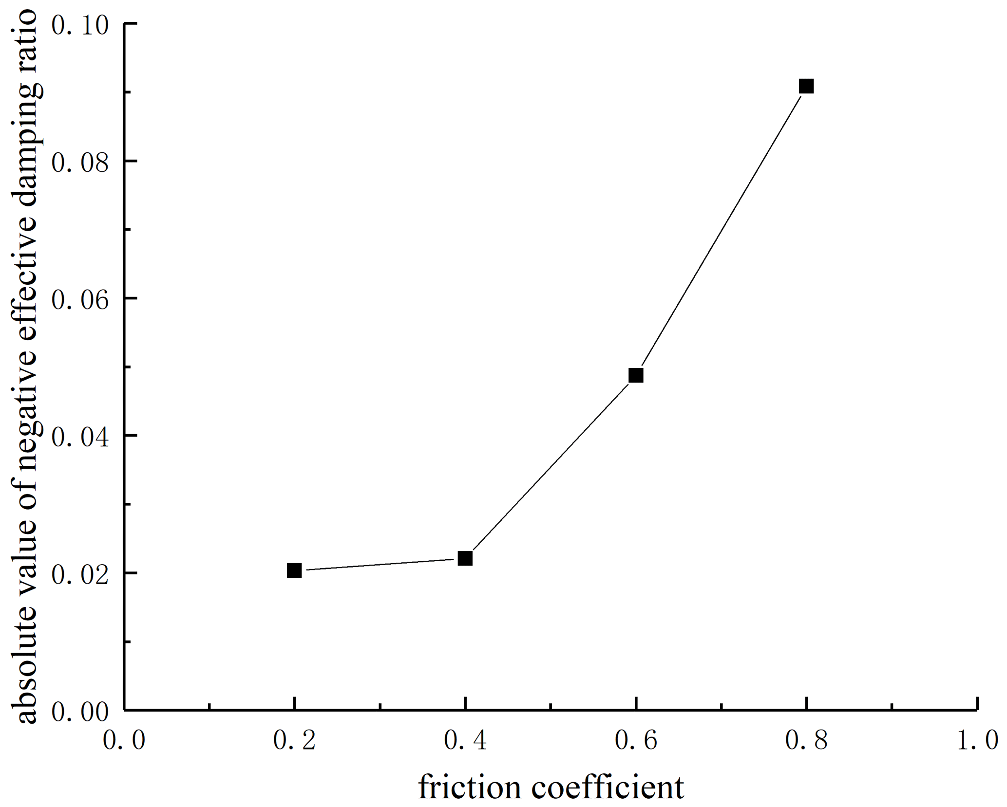
Figure 7Influence of friction coefficients on the vibration stability of the wheel–rail system.
Figure 7 shows the trend of the absolute values of the minimum negative effective damping ratios changing with friction coefficients. It can be seen that the absolute values of the minimum negative effective damping ratios increase with the increase in friction coefficients; that is, the occurrence possibility of unstable vibration of the wheel–rail system increases gradually, indicating that the occurrence possibility of rail corrugation will increase with the increase in friction coefficients. Furthermore, it can be observed that the absolute values of the minimum negative effective damping ratios show a parabola-like growth with the increase in friction coefficients, which illustrates that the friction coefficient has great influence on the stability of the wheel–rail system. When the wheel–rail friction coefficient reaches 0.4, the absolute values of the minimum negative effective damping ratios show a sharp growth trend. Therefore, on the premise of ensuring the normal wheel–rail contact and traction/braking demand, the friction coefficient of the wheel–rail contact surface should be controlled below 0.4 by oiling and other ways so as to better control the development rate of rail corrugation.
4.3 Influence of superelevation and speed matching on wheel–rail system instability
In the curve section, the centrifugal force will push the vehicle to the outer rail, resulting in uneven stress on two rails. Therefore, it is necessary to set a proper height difference between the inner rail and outer rail in the curve line, i.e., superelevation, so that the gravity of the vehicle will generate a centripetal horizontal component force to offset the centrifugal force, so as to achieve the purpose of uniform stress on inner and outer rails.
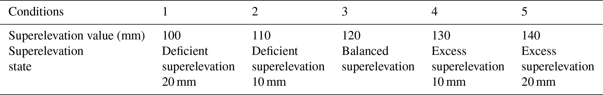
According to Eq. (8) of superelevation calculation, when the vehicle running speed is v=60 km/h and the curve radius is Rr=350 m, the calculated superelevation value is 120 mm (a multiple of 5 mm). Based on that, this section calculates five working conditions of h=100, 110, 120, 130, and 140 mm, respectively, as shown in Table 4. At the same time, the vertical stiffness of fasteners is 20 MN/m, the lateral stiffness is 10 MN/m, and the wheel–rail friction coefficient is 0.4.
where h is the superelevation of the outer rail in millimeters; v is the vehicle speed in km/h; and Rr is the curve radius in meters.
Table 4Calculation conditions of different superelevation states.
By using the finite-element model of the wheel–rail system, the lateral inclination of the slab is adjusted to meet the corresponding requirement of the superelevation setting. Meanwhile, the matching of different superelevation and speeds will lead to the redistribution of vertical and lateral suspension forces of the wheel–rail system; therefore, before the complex eigenvalue calculation of each working condition, it is necessary to use the vehicle–track space coupled dynamic model established by the UM to calculate and extract the inside and outside wheel–rail contact angles, the vertical and lateral suspension forces at both ends, and other parameters and adjust them to the finite-element analysis model for complex eigenvalue calculations.
Figures 8–9 show the distribution diagram of negative effective damping ratios and the corresponding dominant mode diagrams under different working conditions. It can be seen that when the track structure is at superelevation states of 100, 110, 120, 130, and 140 mm, the corresponding minimum negative effective damping ratios are −0.04832, −0.03356, −0.02209, −0.03473, and −0.04089, and frequencies are 202.8, 206.3, 202.3, 207.9, and 205.1 Hz.
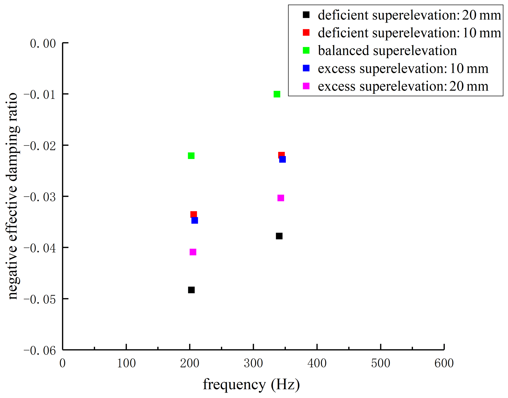
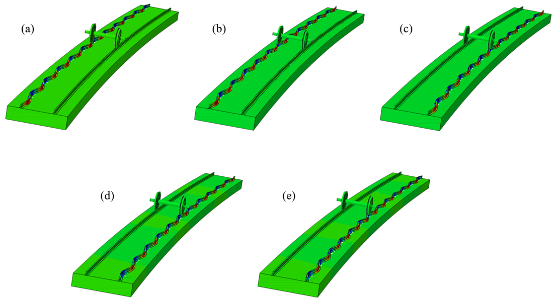
Figure 9Dominant mode diagrams. (a) Deficient superelevation: 20 mm. (b) Deficient superelevation: 10 mm. (c) Balanced superelevation. (d) Excess superelevation: 10 mm. (e) Excess superelevation: 20 mm.
According to Figs. 8–9, it can be established that under conditions of deficient superelevation, balanced superelevation, and excess superelevation of the track structure, the wheel–rail systems all have unstable vibration modes. When the track structure is at deficient superelevation states, the unstable vibration modes corresponding to the minimum effective damping ratios mainly appear at the outer wheel–outer rail. When the track structure is at balanced superelevation and excess superelevation states, the unstable vibration modes corresponding to the minimum effective damping ratios appear at the inner wheel–inner rail, and the absolute value of the negative effective damping ratio corresponding to the balanced superelevation state is relatively small, which shows that the occurrence probability of unstable vibration of the wheel–rail system in this state is relatively low; that is, the occurrence probability of rail corrugation in this state is relatively low. Therefore, the variation of superelevation states of the track structure plays an important role in the stability of the wheel–rail system. The superelevation state directly affects the formation of rail corrugation and determines the development order of corrugation of the inner and outer rails. This conclusion can well explain the phenomenon of corrugation appearing on only one side rail.
Based on the calculation results, it is found that increasing vertical and lateral stiffnesses of fasteners can remarkably decrease the occurrence possibility of corrugation, which is consistent with the literature (Cui et al., 2016). In the literature (Cui et al., 2016), it can be seen that rail corrugation did not occur when the Cologne-egg fasteners were replaced with the DTVI2 fasteners whose vertical support stiffness was about 4 times as high as that of the Cologne-egg fasteners. Moreover, it is established that the wheel–rail friction coefficient should be controlled below 0.4 to inhibit the development of rail corrugation, which is similar to the conclusion of the literature (Chen et al., 2010). In the literature (Chen et al., 2010), it can be known that the propensity for corrugation occurrence increased when increasing the wheel–rail friction coefficient. The above results have a certain guiding significance for the maintenance of metro lines.
This study carries out the complex eigenvalue analysis of influence factors of rail corrugation by using the three-dimensional finite-element model of a wheel–rail system based on the theory of friction self-excited vibration. Through the stability analysis of a wheel–rail system with different vertical and lateral stiffnesses of fasteners, different friction coefficients, and different track structure superelevation, it can be seen that properly improving the vertical and lateral stiffnesses of fasteners, controlling the wheel–rail friction coefficient below 0.4, and maintaining the balanced superelevation of the track structure can effectively reduce the occurrence possibility of unstable vibration of the wheel–rail system and thus inhibit the generation and development of rail corrugation.
The excess superelevation states of the track structure result in the unstable friction self-excited vibration of the wheel–rail system at the inner wheel–inner rail, while the deficient superelevation states result in the unstable friction self-excited vibration of the wheel–rail system at the outer wheel–outer rail, which indicates that the setting of superelevation states of the track structure directly affects the formation of rail corrugation and determines the development order of corrugation of the inner and outer rails. This conclusion can well explain the phenomenon of corrugation appearing only on one side rail.
This study conducts parametric research on the influencing factors of rail corrugation by using the index of effective damping ratio, but the index can not directly reflect the occurrence and development process of rail corrugation. In order to further understand the phenomenon of rail corrugation, future research will focus on the quantitative evaluation index of rail corrugation.
All the data used in this paper can be obtained from the corresponding author upon request.
ZW carried out the modeling, simulations, and writing of the paper; ZL provided guidance on the theoretical methods and reviewed the paper.
The authors declare that they have no conflict of interest.
This research has been supported by the National Natural Science Foundation of China (grant no. 11772230).
This paper was edited by Daniel Condurache and reviewed by Guilin Wen and one anonymous referee.
Chen, G. X., Zhou, Z. R., Ouyang, H., Jin, X. S., Zhu, M. H., and Liu, Q. Y.: A finite element study on rail corrugation based on saturated creep force-induced self-excited vibration of a wheelset–track system, J. Sound Vib., 329, 4643–4655, https://doi.org/10.1016/j.jsv.2010.05.011, 2010.
Chen, G. X., Zhang, S., Wu, B. W., Zhao, X. N., Wen, Z. F., Ouyang, H., and Zhu, M. H.: Field measurement and model prediction of rail corrugation, P. I. Mech. Eng. F-J. Rai., 234, 381–392, https://doi.org/10.1177/0954409719877318, 2020.
Cui, X. L., Chen, G. X., Yang, H. G., Zhang, Q., Ouyang, H., and Zhu, M. H.: Study on rail corrugation of a metro tangential track with Cologne-egg type fasteners, Vehicle Syst. Dyn., 54, 353–369, https://doi.org/10.1080/00423114.2015.1137955, 2016.
Cui, X. L., Chen, G. X., and Yang, H. G.: Influence of wheelset structure and fastener stiffness on rail corrugation, Journal of Southwest Jiaotong University, 52, 112–117, https://doi.org/10.3969/j.issn.0258-2724.2017.01.016, 2017.
Cui, X. L., Yan, S., and Chen, G. X.: Field measurement and numerical simulation for rail corrugation in sector of fixed dual short sleeper, Journal of Vibration and Shock, 37, 171–176, https://doi.org/10.13465/j.cnki.jvs.2018.13.027, 2018.
Cui, X. L., Chen, G. X., and Ouyang, H.: Study on the effect of track curve radius on friction-induced oscillation of a wheelset–track system, Tribol. T., 62, 1–30, https://doi.org/10.1080/10402004.2019.1601317, 2019.
Grassie, S. L. and Kalousek, J.: Rail corrugation: characteristics, causes and treatments, P. I. Mech. Eng. F-J. Rai., 207, 57–68, https://doi.org/10.1243/PIME_PROC_1993_207_227_02, 1993.
Jin, X. S. and Wen, Z. F.: Rail corrugation formation studied with a full-scale test facility and numerical analysis, P. I. Mech. Eng., J-J. Eng., 221, 675–698, https://doi.org/10.1243/13506501JET269, 2007.
Jin, X. S., Wen, Z. F., Wang, K. Y., and Zhang, W. H.: Effect of a scratch on curved rail on initiation and evolution of rail corrugation, Tribol. Int., 37, 385–394, https://doi.org/10.1016/j.triboint.2003.07.002, 2004.
Jin, X. S., Wen, Z. F., Wang, K. Y., and Xiao, X. B.: Effect of passenger car curving on rail corrugation at a curved track, Wear, 260, 619–633, https://doi.org/10.1016/j.wear.2005.03.016, 2006.
Kurzeck, B.: Combined friction induced oscillations of wheelset and track during the curving of metros and their influence on corrugation, Wear, 271, 299–310, https://doi.org/10.1016/j.wear.2010.10.049, 2011.
Lei, Z. Y. and Wang, Z, Q.: Generation mechanism and development characteristics of rail corrugation of Cologne egg fastener track in metro, KSCE J. Ci. Eng., 24, 1763–1774, https://doi.org/10.1007/s12205-020-1614-9, 2020.
Lei, Z. Y., Wang, Z. Q., Li, L., and Geng, C. Z.: Rail corrugation characteristics of the common fastener track in metro, Journal of Tongji University (Natural Science), 47, 1334–1340, https://doi.org/10.11908/j.issn.0253-374x.2019.09.014, 2019.
Li, W.: Study on root cause of metro rail corrugation and its influence on behavior of vehicle/track system, PhD thesis, State Key Laboratory of Traction Power, Southwest Jiaotong University, China, 251 pp., 2015.
Li, W., Wang, H. Y., Wen, Z. F., and Du, X.: An investigation into the mechanism of metro rail corrugation using experimental and theoretical methods, P. I. Mech. Eng. F-J. Rai., 230, 1025–1039, https://doi.org/10.1177/0954409715596182, 2016.
Li, X.: Study on the mechanism of rail corrugation on subway track, PhD thesis, State Key Laboratory of Traction Power, Southwest Jiaotong University, China, 196 pp., 2012.
Li, X., Li, W., Shen, Y. Y., Wen, Z. F., and Jin, X. S.: Study on the rail corrugation of the ladder-type sleepers track based on the track vibration theory, J. Mech. Eng., 52, 121–128, https://doi.org/10.3901/JME.2016.22.121, 2016.
Li, Y.: Causes of low rail corrugation and little high rail corrugation in minor radius curve route, Surf. Technol., 46, 134–139, https://doi.org/10.16490/j.cnki.issn.1001-3660.2017.08.022, 2017.
Meehan, P. A., Batten, R. D., and Bellette, P. A.: The effect of non-uniform train speed distribution on rail corrugation growth in curves/corners, Wear, 366–367, 27–37, https://doi.org/10.1016/j.wear.2016.05.009, 2016.
Oostermeijer, K. H.: Review on short pitch rail corrugation studies, Wear, 265, 1231–1237, https://doi.org/10.1016/j.wear.2008.01.037, 2008.
Piotrowski, J. and Kik, W.: A simplified model of wheel/rail contact mechanics for non-Hertzian problems and its application in rail vehicle dynamic simulations, Vehicle Syst. Dynam., 46, 27–48, https://doi.org/10.1080/00423110701586444, 2008.
Sato, Y., Matsumoto, A., and Knothe, K.: Review on rail corrugation studies, Wear, 253, 130–139, https://doi.org/10.1016/S0043-1648(02)00092-3, 2002.
Saulot, A., Descartes, S., Desmyter, D., Levy, D., and Berthier, Y.: A tribological characterization of the “damage mechanism” of low rail corrugation on sharp curved track, Wear, 260, 984–995, https://doi.org/10.1016/j.wear.2005.06.004, 2006.
Sun, J. L., Li, H. M., Hou, M. R., and Sun, L. X.: Discussion on the coupling dynamic simulation calculation method for vehicle-track-bridge large system of railway, Railway Eng., 58, 104–107, https://doi.org/10.3969/j.issn.1003-1995.2018.02.26, 2018.
Wen, Z. F., Jin, X. S., Xiao, X. B., and Zhou, Z. R.: Effect of a scratch on curved rail on initiation and evolution of plastic deformation induced rail corrugation, Int. J. Solids Struct., 45, 2077–2096, https://doi.org/10.1016/j.ijsolstr.2007.11.013, 2008.
Xiao, X. L.: Study of rail corrugation on tangential tracks based on self-excited vibration of a wheelset-track-sleeper system, Master thesis, Tribology Research Institute, Southwest Jiaotong University, China, 57 pp., 2012.
Xie, G. and Iwnicki, S. D.: Calculation of wear on a corrugated rail using a three-dimensional contact model, Wear, 265, 1238–1248, https://doi.org/10.1016/j.wear.2008.01.026, 2008.
Yan, S., Zhao, X. N., Cui, X. L., and Chen, G. X.: Influence of wheel/rail contact parameters on rail corrugation, Lubr. Eng., 43, 42–46, https://doi.org/10.3969/j.issn.0254-0150. 2018.11.008, 2018.
Zhang, H. G.: Mechanisms and treatment solutions for rail corrugation on Beijing Metro, PhD thesis, School of Civil Engineering and Architecture, Beijing Jiaotong University, China, 215 pp., 2015.
Zhang, H. G., Liu, W. N., Wang, J., and Sun, J. J.: Measurement specifications and assessment criteria for rail corrugation, Urban Rapid Rail Transit, 26, 27–32, https://doi.org/10.3969/j.issn.1672-6073.2013.06.008, 2013.
Zhao, J. W., Zhao, X. N., Chen, G. X., Ouyang, H., and Cui, X. L.: Effect of fastener parameters on rail corrugation of metro tight curve track, Railway Standard Design, 62, 6–10, https://doi.org/10.13238/j.issn.1004-2954.201801040008, 2018.
- Abstract
- Introduction
- Vehicle–track space coupled dynamic model
- Friction self-excited vibration model of the wheel–rail system
- Analysis of influence factors of rail corrugation
- Discussion
- Conclusions
- Data availability
- Author contributions
- Competing interests
- Financial support
- Review statement
- References