the Creative Commons Attribution 4.0 License.
the Creative Commons Attribution 4.0 License.
 | 17 Feb 2021
Crack identification in cyclic symmetric structures based on relative indicators of frequency separation
Shuai Wang
Menghui Liang
Cyclic symmetric structures are an important class of structures in the fields of civil and mechanical engineering. In order to avoid accidents due to cracks in such structures, an effective method for crack identification is presented in this paper. First, the dynamic model of cyclic symmetric structures with gapless cracks is developed using a structure's sector model and rotation transformation. Then, the effects of cracks on the free vibration characteristics of a cracked cyclic symmetric structure are addressed, with particular interests in the distortion of mode shapes and the shift and split of natural frequencies. On the basis of crack-induced phenomena, an effective method based on relative indicators of frequency separation is developed for quantitative crack identification. Numerical results illustrate that the relative indicators are sensitive to small cracks and insensitive to the predicting model used during analysis. Finally, the method is validated by experiments conducted on an impeller-shaft assembly. The results show the effectiveness of the frequency separation indicators in crack identification in cyclically symmetric structures.
- Article
(4442 KB) - Full-text XML
- BibTeX
- EndNote


Cyclic symmetric structures, also referred to as rotational symmetric structures, are an important class of structures in the fields of mechanical and civil engineering, such as gears, fans, bladed disks of aero-engines, or impellers of centrifugal compressors. Due to their importance and extensive application, dynamic modelling and vibration analysis of cyclic symmetric structures have attracted the attention of many researchers in the past few decades and formed a special category in structural dynamics (Thomas, 1979). These structures often operate under harsh conditions, including high temperature, high pressure, high rotating speed and high cyclic stress. Crack damages may occur at the weak points due to high cycle fatigue after several years of operation. In order to avoid severe accidents caused by cracks, effective techniques should be developed to identify the crack damages, at best in the early stage or at least before breakage.
Crack identification is also a crucial issue in the field of structural health monitoring and has attracted a lot of attention from researchers in the civil and mechanical engineering communities. In the past few decades, a large number of investigations have been conducted on identifying crack damages in beams (Janeliukstis et al., 2017; Xiang and Liang, 2012; Yang et al., 2017), plates (Katunin, 2011; Yang and Oyadiji, 2017; Yang et al., 2013), rotors (Guo et al., 2017; Kumar and Rastogi, 2009; Lu and Chu, 2011; Papadopoulos, 2008; Sawicki et al., 2011; Zhang et al., 2013), impellers (Wang et al., 2014, 2015), bridges (Dilena et al., 2015; Kim et al., 2018; Lee et al., 2005) and some other structures (Elshafey et al., 2010; Katunin et al., 2015; Viglietti et al., 2018). More extensive literature summaries on damage identification can be found in several review papers (Carden and Fanning, 2004; Doebling et al., 1998, 1996; dos Santos et al., 2008; Fan and Qiao, 2011; Salawu, 1997; Yao et al., 2014). As is mentioned in some papers (Carden and Fanning, 2004; Doebling et al., 1998, 1996; dos Santos et al., 2008; Fan and Qiao, 2011; Salawu, 1997; Yao et al., 2014), the available literature can be classified, according to the features extracted for damage identification, as natural frequency-based methods, mode shape-based methods, mode shape curvature/strain mode shape-based methods and other methods based on modal parameters. These large numbers of investigations provide effective methods and techniques for crack identification and greatly promote the progress of structural healthy monitoring in both the academic and engineering fields. Despite the achievements, methods for identifying crack damage in cyclic symmetric structures are rarely reported. Different from beams, plates and other types of structures, cyclic symmetric structures have some unique characteristics, which may provide valuable indicators for crack identification.
Regarding the studies on cyclic symmetric structures, most investigations are concentrated on the dynamic modelling (Lalanne, 2005; Laxalde and Pierre, 2011; Petrov, 2003), vibration and stability analysis (Grolet and Thouverez, 2012; Jacquet-Richardet et al., 1996; Sarrouy et al., 2011; Tai and Shen, 2013) and model order reduction methods (Tran, 2009, 2014). Among these studies, a considerable portion is conducted on bladed disks, which are important parts of aero-engines and axial flow turbine machines. With respect to the relatively few studies on cracks in cyclic symmetric structures, Ramesh et al. (1997) presented a numerical method for evaluating the stress intensity factor of radial cracks in thick cyclic symmetric annular rings. Saito et al. (2009) studied the effects of cracks on the nonlinear forced response of a bladed disk using the finite-element model and component-mode synthesis method. Marinescu et al. (2011) developed an efficient reduced order model for vibration analysis of mistuned cracked bladed disks. D'Souza et al. (2012) presented a model order reduction method for nonlinear analysis of cracked multistage bladed-disk systems. Wang et al. (2014) addressed the influences of cracks and mistuning on the forced response and resonant frequencies of impellers. Jung et al. (2012) studied the effects of cracks on a mistuned bladed disk and discussed the possibility of detecting crack damage by employing vibration data. Despite the abundant investigations, relatively few papers were published to deal with crack identification in cyclic symmetric structures.
In this paper, an effective method for identifying crack damages in cyclic symmetric structures is presented. First, the dynamic model of a cyclic symmetric structure with a gapless crack is developed. Then, the influences of crack damage on the variation characteristics of mode shapes and natural frequencies of cyclic symmetric structures are discussed. On this basis, relative indicators, which are based on the separations of the natural frequency pairs with the same nodal diameter, are developed for crack identification. Finally, an experiment is conducted on a cracked impeller-rotor assembly to validate the proposed method.
This paper is organized as follows. Section 2 addresses the dynamic modelling of a cracked cyclic symmetric structure. In Sect. 3, the characteristics of mode shapes and natural frequencies of cracked cyclic symmetric structures are presented. Section 4 presents the frequency separation indicators for crack identification. Section 5 contains the experiment results. Conclusions are given in Sect. 6.
In vibration analysis of cyclic symmetric structures, the sector models are often employed, instead of the entire model, to significantly reduce the computational requirement. This advantage is still valuable nowadays in spite of the advances in computer hardware, as practical cyclic symmetric structures are often very complicated where large finite-element models are usually needed to obtain accurate vibration characteristics. A critical issue in modelling cracked cyclic symmetric structures is the accurate modelling of cracks, which is often gapless and possesses a complex shape. The methods based on the theory of fracture mechanics mainly deal with relatively simple and non-erratic structures by describing cracks as the reduction of stiffness. Besides, the property of cyclic symmetry is broken when there exists a crack in the structure. With respect to this issue, an efficient approach for modelling cracked cyclic symmetric structures is developed by utilizing the sector model. As a sector model is generally much more regular than the entire one, this approach can reduce the difficulties in the preprocessing steps. Figure 1 shows the finite-element model of a cracked disk, which is used herein as an example.
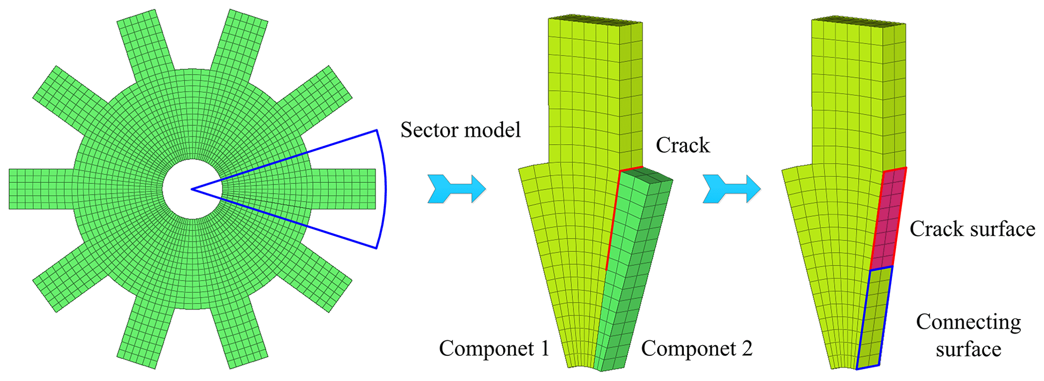
First, the sector model is utilized and split into two components according to the position of the crack. As is shown in Fig. 1, the common section between the two components is divided into the connecting and crack surfaces, respectively, where the shape and size of the crack surface depend on the problem of interest. As the name implies, the connecting surface is used to connect the two components. The governing equations of motion of the two components are obtained independently, so that the degrees of freedom (DOFs) of nodes on the connecting and crack surfaces exist in both of the two equations, which can be expressed as
where superscript “c” is a label representing different components; M(c) and are the mass and stiffness matrices; u(c) denotes the vector of nodal displacement; , and represent the force vectors with respect to the DOFs of nodes on the connecting surface, the crack surface and the external excitation, respectively.
Then, the two independent governing equations are synthesized to form that of the whole cracked sector model. The vectors u(c) are firstly reorganized as
where the subscript “oth” denotes the nodal displacement regarding the other nodes except those on the crack and connecting surfaces. The two components can be connected by applying the displacement compatibility condition , where and are the displacement vectors of the two connecting surfaces. This compatibility condition leads to a coordinate transformation, by which the governing equations of the sector model with a gapless crack can be obtained as
where the superscript “s” denotes the objects of the sector model. As the reaction forces on the connecting surfaces between the two parts are equal but opposite in sign, does not exist.
Finally, the whole cracked model can be obtained by conducting rotation transformation on the sector model shown as
where the superscript “h” denotes the objects regarding the whole model; IS is an identity matrix of dimension S, where S is the number of sectors; R(h) is a pseudo-block diagonal matrix as
where denotes the rotation transformation matrix from the first sector to the sth sector.
After the rotation transformation, the redundant DOFs on the overlapped boundaries, as well as the crack DOFs in other sectors, should be removed. Finally, the governing equations of the structure with a gapless crack can be expressed as
As the free vibration is of interest in this paper, the force vectors on the right-hand side of Eq. (6) are neglected in further analysis. Although a relatively simple example is illustrated in this section, the presented method can be easily used for other practical complex cyclic symmetric structures.
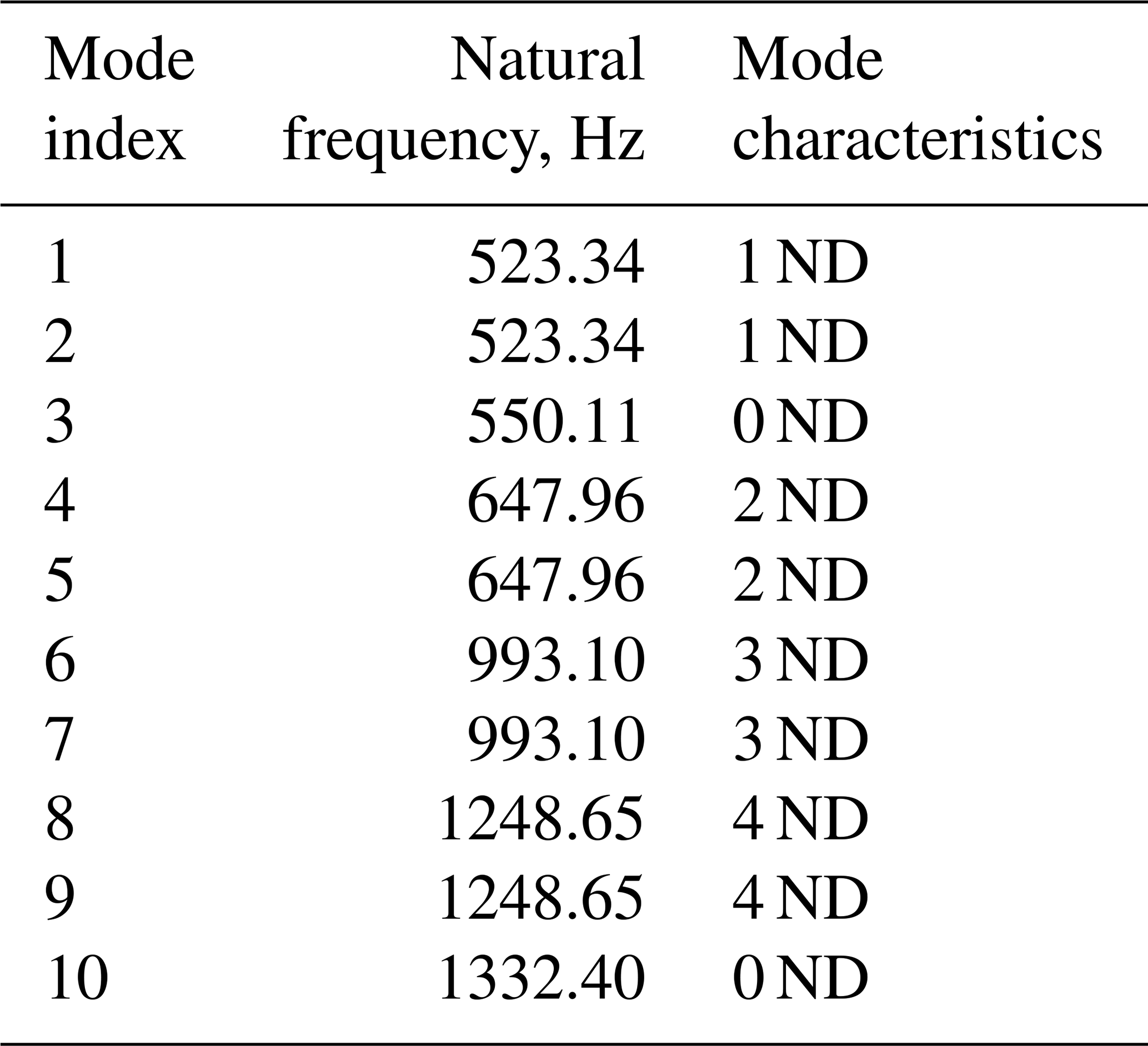
In this section, the effects of cracks on the free vibration of cyclic symmetric structures are presented by employing the disk model shown in Fig. 1 as a representative. During the analysis, the inner circular surface is set to be fixed. As free vibration is of interest, the crack surfaces are set to be free without any constraints during the analysis. The values of the dimension and material parameters of the disk are listed in Table 1. Table 2 shows the first 10 natural frequencies of the healthy disk. An important term in describing the characteristics of mode shapes of cyclic symmetric structures is nodal diameter (ND), which represents the line in the mode shapes with zero amplitude. As is referred to in Thomas (1979), for a mode with 0 ND, each sector has the same mode shape as adjacent sectors. For an mode, if S is even, each sector has the same mode shape but with antiphase as adjacent sectors. For the mode with other ND, each sector has some differences in phase between adjacent sectors, as is shown in Figs. 2 and 3. Moreover, the natural frequencies corresponding to the 1 ND, 2 ND, … modes, which are of interest in this paper, always exist in pairs with identical values, as is shown in Table 2. These characteristics are unique for cyclic symmetric structures.
Table 1Values of the dimension and material parameters of the disk.

Table 2The first 10 natural frequencies of the disk without cracks.
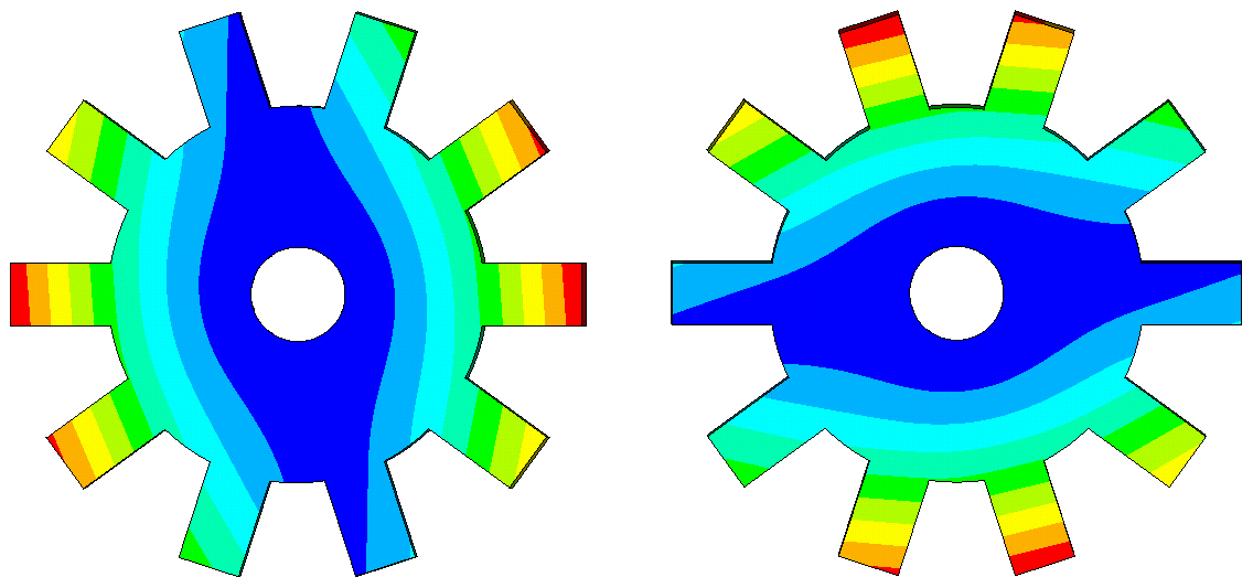
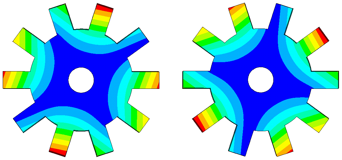
For the sake of comparison, Figs. 4 and 5 show the 1 ND and 2 ND mode shapes of the disk with a 56 mm crack. Due to the influence of cracks, the mode shapes are distorted compared with those of the ones without cracks. The circumferential positions of the nodal lines in the mode shapes of healthy disks are arbitrary, which can be represented by complex counter-rotating waves. The existence of a crack breaks the cyclic symmetry and makes the circumferential positions of nodal lines fixed with respect to the position of the crack. As is shown in Fig. 4, the mode shape pairs of 1 ND have a mode with its nodal line far from the crack and the other one with its nodal line across the crack. Regarding the mode shape pairs of 2 ND shown in Fig. 5, a similar phenomenon can be seen. This is an interesting phenomenon that the mode shapes of the cracked disk seem to become two extreme cases. When the crack is located at the nodal line, the reduction in stiffness is minimum as these positions do not suffer from large bending deformations. For the other ones, the decrease in bending stiffness is significant because of the high strain energy density at the crack location. These characteristics will of course be reflected in the variation of natural frequencies.
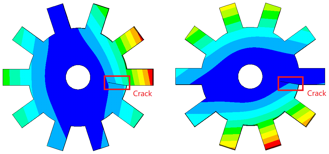
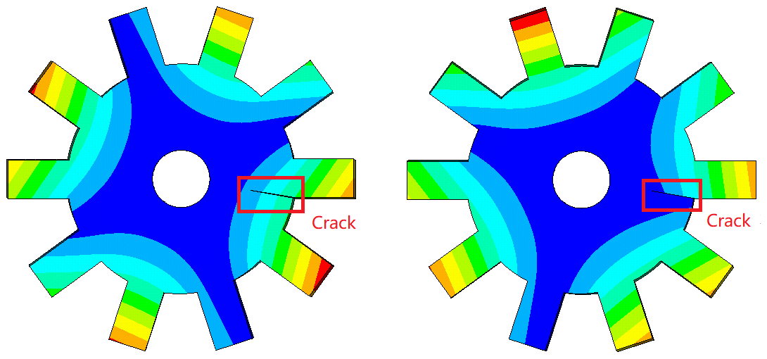
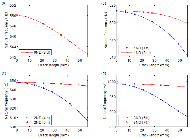
Figure 6Variation of natural frequencies versus crack length: (a) 0 ND, (b) 1 ND, (c) 2 ND and (d) 3 ND. The numbers in brackets denote the order of natural frequencies.
Figure 6 shows the variation of natural frequencies versus crack length, where the natural frequency pairs of 0 ND, 1 ND, 2 ND and 3 ND are included. It can be seen that the crack leads to the obvious decrease in natural frequencies. Another significant phenomenon is that the natural frequency pairs of 1–3 ND get separated due to the crack, and the larger crack causes larger separation. A similar phenomenon of resonant peak split has also been found in the nonlinear forced responses of cracked bladed disks and impellers (D'Souza et al., 2012; Saito et al., 2009; Wang et al., 2014). Resulting from the characteristics of the 1–3 ND mode shapes, the larger ones of the natural frequency pairs decrease much more slowly than the other ones. These characteristics provide effective indicators for crack identification.
Among the numerous studies on crack identification, natural frequency-based methods constitute an important branch, which have been validated by a number of engineering applications. Natural frequency-based methods tend to have the advantages of ease of measurement and being less sensitive to measuring noise. Nevertheless, such methods also possess some limitations, as summarized in some review papers (Carden and Fanning, 2004; Doebling et al., 1998, 1996; dos Santos et al., 2008; Fan and Qiao, 2011; Salawu, 1997; Yao et al., 2014). One of the most significant limitations is the low sensitivity to crack damages. Another important issue is the distinctions between the predicted results and those measured ones. In order to realize quantitative crack identification, dynamic models, either analytical models or finite-element models, are often required to predict the relations between frequency indicators and crack length. Some differences tend to occur between the measured and predicted results, even when a quite refined finite-element model is used. Although model-updating methods can be used to reduce such differences, it is often very cumbersome and inefficient in practical applications.
With regard to these limitations, the phenomenon of frequency separation is utilized in this paper, and relative indicators of frequency separation are employed, instead of the shifts of natural frequencies, for crack identification in cyclic symmetric structures. For a sND natural frequency pair, the frequency separation indicator FsND is defined as
where and are the natural frequencies of the sND mode pair; Sk represents the maximum number of ND, which is determined as
Figure 7 illustrates the separations of the 1 ND, 2 ND, 3 ND and 4 ND natural frequency pairs versus crack length, where the crack surfaces are also set to be free during the analysis. As is shown in the figures, the frequency separation indicators change monotonically with the increase in crack length, and the ones of higher ND tend to vary more remarkably. These characteristics provide valuable information for quantitatively identifying the crack damage. Due to the property of cyclic symmetry, cracks in the same positions of different sectors result in the same variation in natural frequencies. Therefore, the position of the crack can hardly be determined by using only frequency separations, and the mode shapes should also be employed. As is shown in Figs. 4 and 5, the mode shapes of a certain ND always have a mode shape with its nodal line going across the crack. Therefore, the position of the crack can be identified by the modal shapes. In cyclic symmetric structures, cracks usually occur in some fixed positions. For example, the cracks in gears are often located at the tooth root with an inclination angle of 45∘, and the cracks in centrifugal impellers more often occur in the middle positions of blades at the inflow point or the weld toes. This information makes it easier to localize the cracks in cyclic symmetry structures than in beams and plates, as the locations of cracks are usually fixed. Nevertheless, it should be noticed that different types of structures have different characteristics in crack initiation.
An advantage of employing frequency separation indicators is their higher sensitivity to small cracks than the shifts of natural frequencies. This is because the frequency separation is obtained by the relative differences between the natural frequencies in one test, so even a small separation can be seen during tests. The potential distinctions between different tests conducted in different environments can be avoided. By contrast, the methods based on shift of natural frequency generally require reference results of counterparts without cracks. As the reference results may change with environmental and other conditions, a small shift of natural frequency is often not reliable for identifying crack damage.
Another advantage of employing frequency separation indicators is their low sensitivity to the predicting model used during analysis. As is mentioned above, the accuracy of a dynamic model is a critical issue in model-based methods. However, the different models of an identical structure may give different results. Taking the finite-element models as examples, the predicted natural frequencies may differ between models with different numbers of nodes and elements.

Figure 7Separations of the 1 ND, 2 ND, 3 ND and 4 ND natural frequency pairs versus crack length.
Figure 8 illustrates three finite-element models of the disk shown in Fig. 1. The variations of natural frequencies and the frequency separation indicators versus crack length are shown in Figs. 9 and 10, respectively. It can be seen in Fig. 9 that different models give different results in frequency shifts, and the differences sometimes exceed the influences of cracks. Nevertheless, the variation curves of the frequency separation indicators of the models are very close. Then, a relatively rough model can be employed to acquire the variation of frequency separation versus crack length. It can also be inferred that the relative indicators can more reliably resist the variation of the external environment. This is because the natural frequency pairs may have similar levels of variation due to environment change, so the separation indicators may not change much.
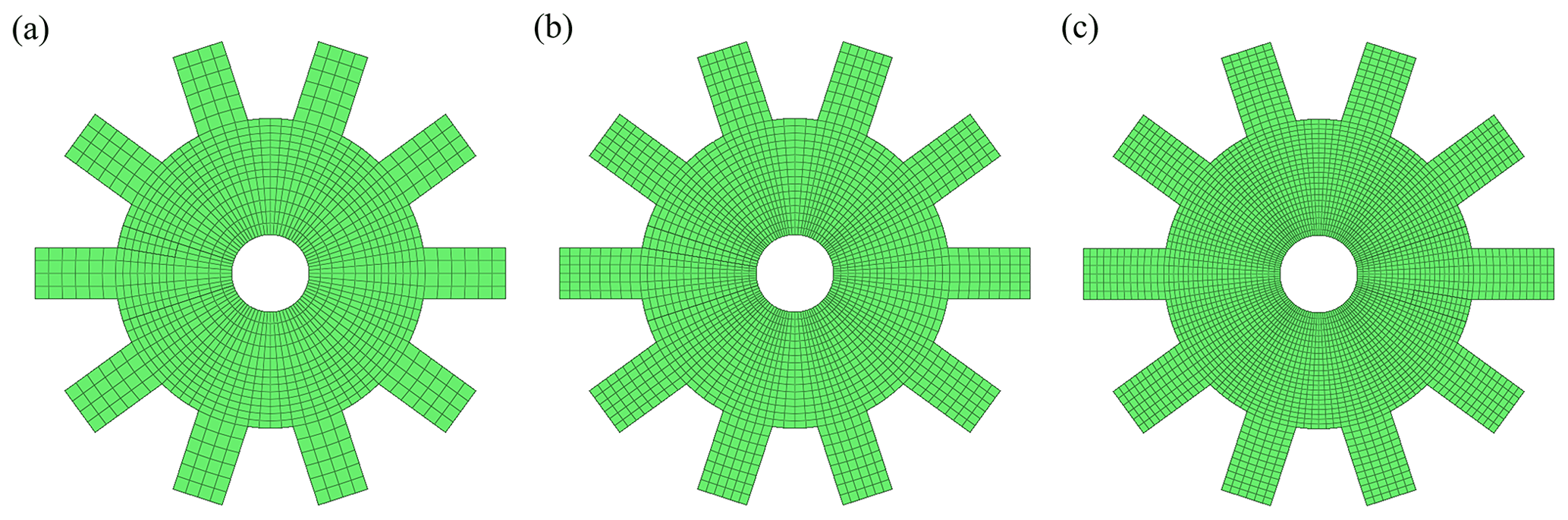
Figure 8Finite-element models of the disk with a gapless crack: (a) model 1 with 4260 nodes, (b) model 2 with 6780 nodes and (c) model 3 with 14 400 nodes.
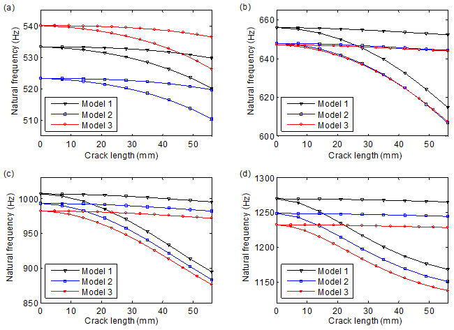
Figure 9Variation of natural frequencies versus crack length: (a) 1 ND, (b) 2 ND, (c) 3 ND and (d) 4 ND. Models 1, 2 and 3 possess 4260, 6780 and 14 400 nodes, respectively.
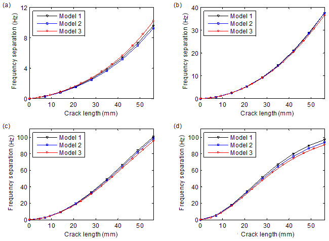
Figure 10Variation of frequency separations versus crack length: (a) 1 ND, (b) 2 ND, (c) 3 ND and (d) 4 ND. Models 1, 2 and 3 possess 4260, 6780 and 14 400 nodes, respectively.
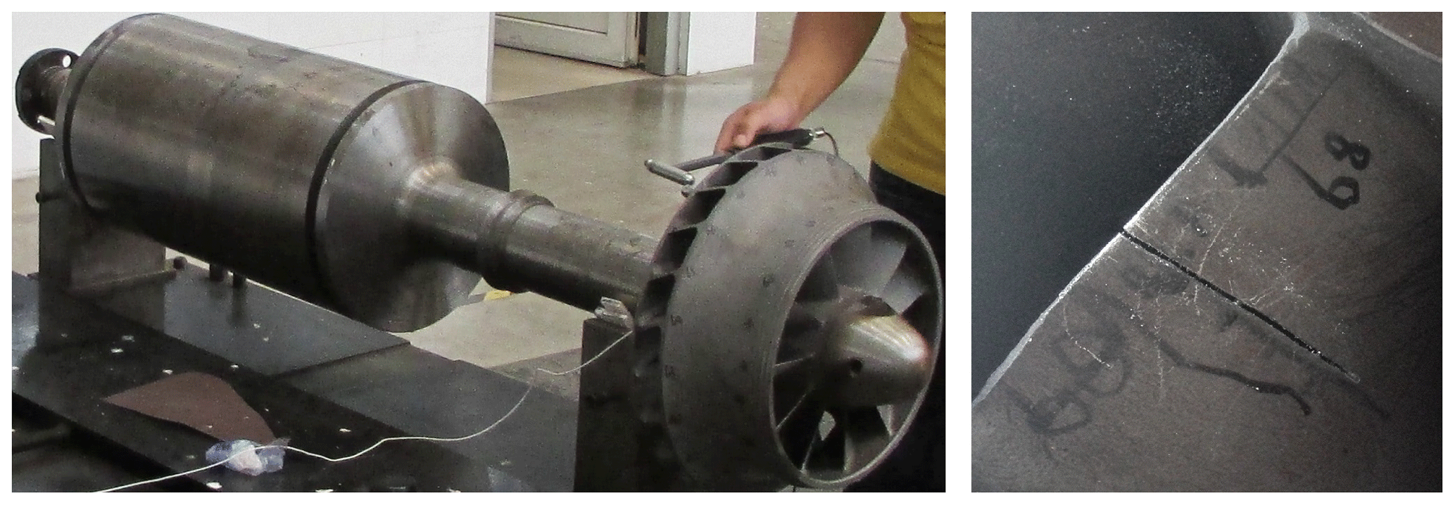
In order to validate the proposed method and illustrate its effectiveness in practical cyclic symmetric structures, modal tests are conducted on an impeller-shaft assembly with a crack located in the middle position of the blade, as is shown in Fig. 11. The assembly is the rotor of a centrifugal compressor and contains a shaft, an impeller and a fastening device. As the practical gapless crack is relatively difficult to fabricate, the steel saw is used in the experiment to saw the crack with a small gap. During the test, the impulse excitation method with an aluminium hammer is employed, and the assembly is laid on a V-shaped support. As the localized crack mainly affects the vibration of the impeller, the exciting and measuring points are all placed on the impeller. During the tests, the crack is fabricated on the impeller by five stages with a 10 mm interval in crack length per stage. After the machining of the crack in each stage, a modal test is conducted subsequently.
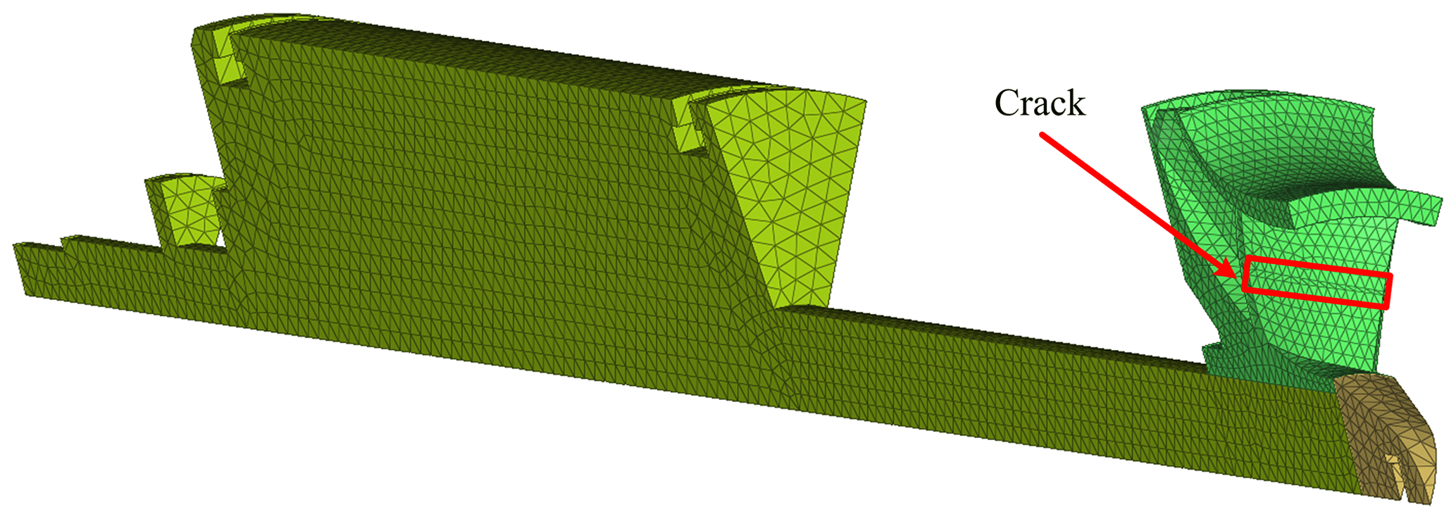
By contrast, Fig. 12 shows the finite-element model of the assembly, which is used in this section to compute the natural frequencies of the cracked assembly. Table 3 lists the 13 natural frequencies of the healthy assembly obtained by the test and finite-element model. As can be seen in Table 3, although a relatively refined finite-element model has been employed, most of the predicted natural frequencies have non-negligible differences compared with the tested ones.
As the exciting and measuring points are placed on the impeller, the measured natural frequencies contain only those with significant impeller-involved mode shapes. Figure 13 shows the tested frequency response functions of six cases of cracks in the impeller. As can be seen in the figure, the two natural frequencies of the 2 ND mode pair, which are boxed with a red dashed frame, present obvious separation, and the value of separation increases monotonously with the crack length. The frequency separation is very sensitive to small cracks, as is already very obvious for a small crack. Thus, the test results conform to the variation characteristics of natural frequencies obtained by numerical analysis in the previous section. Nevertheless, the 1 ND coupling modes are not that sensitive to cracks. This is because these modes involve the coupled deformations of impellers and shafts, where the local crack does not result in a significant reduction in the equivalent bending stiffness. The 3 and 4 ND local modes of the assembly possess larger natural frequencies, which exceed the reliable range of the test and are not illustrated in the figure. For other structures, these modes may be within the measured frequency ranges. The tests show that the local modes are more sensitive to cracks than the coupling modes; thus, these modes should be considered during tests. It is easy to understand because the crack-induced reductions in the overall strain energies are more significant in local modes.
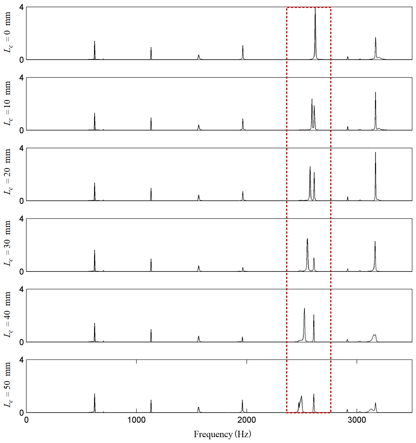
Figure 13Comparisons of the frequency response functions with different lengths of a crack in the impeller. Lc denotes the length of the crack.
Table 3Comparison of the natural frequencies of the impeller-shaft assembly.
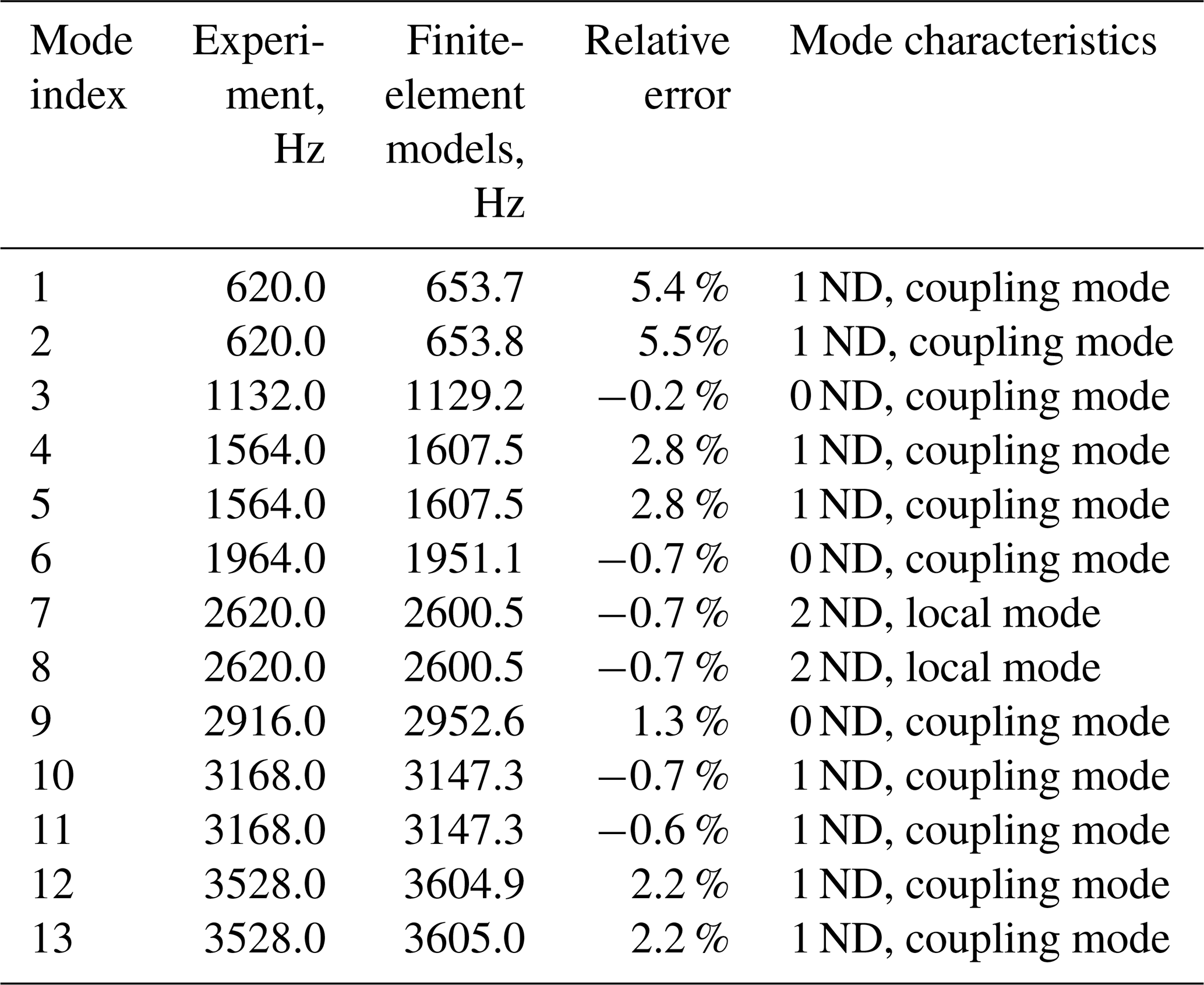
Figure 14a and b show the shifts and separations of the natural frequency pair of 2 ND modes versus crack length, respectively. It can be seen in the figures that the frequency separation predicted by the finite-element model agrees well with that obtained by tests, though there exist some small differences, whereas the shifts of natural frequencies differ much more obviously. This also illustrates the advantage of employing frequency separation indicators in crack identification in cyclic symmetric structures.

Figure 14Evolutions of the (a) shift and (b) separation of the 2 ND natural frequencies versus crack length.
In practical applications, the separation value of a certain natural frequency pair can be computed first. Then, a modal test is conducted to obtain the realistic separation value. Finally, the length of the crack can be identified by comparing the measured separation value to the predicted relationship of frequency separation versus crack length. If the position of the crack is of interest, the mode shapes should be measured, and then the crack can be localized by the nodal lines in the mode shapes. If the length and position of the crack are not important and when just wondering whether there is existing crack damage, it will be much easier if only one test is needed. The structure's condition can be determined by checking whether there exists a frequency separation phenomenon. Such kinds of qualitative crack identification can meet the requirements of many engineering applications, as the components should be replaced or maintained immediately after finding cracks, in spite of the length of a crack.
The experiment in this section illustrates the effectiveness of the relative indicators of frequency separations in quantitatively identifying crack damage in cyclic symmetric structures. The proposed method also possesses the advantages of being easy to measure and less sensitive to noise, as it is based on a natural frequency test. Although this method is developed with respect to cyclic symmetric structures, the ideas of relative indicators may help to relieve the limitations of insensitivity to small cracks and sensitivity to environment variation of frequency-based methods and may help to develop more reliable techniques for crack identification in beams, plates and other kinds of structures.
In this paper, an effective method is proposed for crack identification in cyclic symmetric structures by using relative indicators of frequency separation. First, the dynamic model of cyclic symmetric structures with gapless cracks is developed using a structure's sector model and rotation transformation. Then, the effects of cracks on the mode shapes and the natural frequencies of a cyclic symmetric structure are addressed. By employing the influence characteristics of cracks, frequency separation indicators are developed for quantitative crack identification. An experiment is also conducted to validate the indicators. According to the results in this paper, it can be concluded that the existence of cracks leads to the distortion of mode shapes and the shift and separation of natural frequencies. The two natural frequencies of a mode pair get gradually decreased and separated as the crack length increases. The mode shape pair also presents different characteristics, where one has a nodal line across the crack and the nodal lines of the other one are far from the crack. These characteristics can be used to identify the position of a crack and quantify the length of the crack. Numerical and experimental results show the effectiveness of the method for crack identification in cyclic symmetric structures. It is also illustrated that the frequency separation indicators have the advantages of being sensitive to small cracks and insensitive to the predicting model used during analysis. Although the method is proposed with respect to cyclic symmetric structures, it may provide some valuable inspirations for developing effective methods for other kinds of structures.
The code/data used to support the findings of this study are available from the corresponding author upon request.
SW conceived the presented idea and wrote the manuscript. SW and ML performed the simulation and experiment. Both the authors approved the final manuscript for publication.
The authors declare that they have no conflict of interest.
This article is part of the special issue “Robotics and advanced manufacturing”. It is not associated with a conference.
This research has been supported by the National Natural Science Foundation of China (grant no. 51805130), the China Postdoctoral Science Foundation (grant no. 2018M632521), the Natural Science Foundation of Anhui Province (grant no. 1808085QE138), and the Fundamental Research Funds for the Central Universities (grant no. JZ2020HGTB0046).
This paper was edited by Bo Li and reviewed by three anonymous referees.
Carden, E. P. and Fanning, P.: Vibration based condition monitoring: a review, Struct. Health Monit., 3, 355–377, https://doi.org/10.1177/1475921704047500,2004.
D'Souza, K., Saito, A., and Epureanu, B. I.: Reduced-order modeling for nonlinear analysis of cracked mistuned multistage bladed-disk systems, AIAA J., 50, 304–312, https://doi.org/10.2514/1.J051021,2012.
Dilena, M., Limongelli, M., and Morassi, A.: Damage localization in bridges via the FRF interpolation method, Mech. Syst. Signal Pr., 52, 162–180, https://doi.org/10.1016/j.ymssp.2014.08.014, 2015.
Doebling, S. W., Farrar, C. R., and Prime, M. B.: A summary review of vibration-based damage identification methods, Shock Vib., 30, 91–105, https://doi.org/10.1177/058310249803000201, 1998.
Doebling, S. W., Farrar, C. R., Prime, M. B., and Shevitz, D. W.: Damage identification and health monitoring of structural and mechanical systems from changes in their vibration characteristics: a literature review, Foreign Language Teaching Res. Press, Los Alamos National Lab., NM, USA, LA-13070-MS, ON: DE96012168, https://doi.org/10.2172/249299, 1996.
dos Santos, J. A., Maia, N., Soares, C. M., and Soares, C. M.: Structural damage identification: a survey, Trends In Computational Structures Technology, 1, 1–24, https://doi.org/10.4203/csets.19.1, 2008.
Elshafey, A. A., Haddara, M. R., and Marzouk, H.: Damage detection in offshore structures using neural networks, Mar. Struct., 23, 131–145, https://doi.org/10.1016/j.marstruc.2010.01.005, 2010.
Fan, W. and Qiao, P.: Vibration-based damage identification methods: a review and comparative study, Struct. Health Monit., 10, 83–111, https://doi.org/10.1177/1475921710365419, 2011.
Grolet, A. and Thouverez, F.: Free and forced vibration analysis of a nonlinear system with cyclic symmetry: Application to a simplified model, J. Sound Vib., 331, 2911–2928, https://doi.org/10.1016/j.jsv.2012.02.008, 2012.
Guo, C., Yan, J., and Yang, W.: Crack detection for a Jeffcott rotor with a transverse crack: An experimental investigation, Mech. Syst. Signal Pr., 83, 260–271, https://doi.org/10.1016/j.ymssp.2016.06.011, 2017.
Jacquet-Richardet, G., Ferraris, G., and Rieutord, P.: Frequencies and modes of rotating flexible bladed disc-shaft assemblies: a global cyclic symmetry approach, J. Sound Vib., 191, 901–915, https://doi.org/10.1006/jsvi.1996.0162, 1996.
Janeliukstis, R., Rucevskis, S., Wesolowski, M., and Chate, A.: Experimental structural damage localization in beam structure using spatial continuous wavelet transform and mode shape curvature methods, Measurement, 102, 253–270, https://doi.org/10.1016/j.measurement.2017.02.005, 2017.
Jung, C., Saito, A., and Epureanu, B. I.: Detection of cracks in mistuned bladed disks using reduced-order models and vibration data, J. Vib. Acoust., 134, 061010, https://doi.org/10.1115/1.4007244, 2012.
Katunin, A.: Damage identification in composite plates using two-dimensional B-spline wavelets, Mech. Syst. Signal Pr., 25, 3153–3167, https://doi.org/10.1016/j.ymssp.2011.05.015, 2011.
Katunin, A., Dragan, K., and Dziendzikowski, M.: Damage identification in aircraft composite structures: A case study using various non-destructive testing techniques, Composite structures, 127, 1–9, https://doi.org/10.1016/j.compstruct.2015.02.080, 2015.
Kim, I.-H., Jeon, H., Baek, S.-C., Hong, W.-H., and Jung, H.-J.: Application of Crack Identification Techniques for an Aging Concrete Bridge Inspection Using an Unmanned Aerial Vehicle, Sensors, 18, 1881, https://doi.org/10.3390/s18061881, 2018.
Kumar, C. and Rastogi, V.: A Brief Review on Dynamics of a Cracked Rotor, Int. J. Rotating Machinery, 2009, 6, https://doi.org/10.1155/2009/758108, 2009.
Lalanne, B.: Perturbations methods in structural dynamics and applications to cyclic symmetric domains, J. Eng. Gas. Turb. Power., 127, 654–662, https://doi.org/10.1115/1.1924430, 2005.
Laxalde, D. and Pierre, C.: Modelling and analysis of multi-stage systems of mistuned bladed disks, Comput. Struct., 89, 316–324, https://doi.org/10.1016/j.compstruc.2010.10.020, 2011.
Lee, J. J., Lee, J. W., Yi, J. H., Yun, C. B., and Jung, H. Y.: Neural networks-based damage detection for bridges considering errors in baseline finite element models, J. Sound Vib., 280, 555–578, https://doi.org/10.1016/j.jsv.2004.01.003, 2005.
Lu, W. and Chu, F.: Shaft crack identification based on vibration and AE signals, Shock Vib., 18, 115–126, https://doi.org/10.3233/SAV-2010-0580, 2011.
Marinescu, O., Epureanu, B. I., and Banu, M.: Reduced Order Models of Mistuned Cracked Bladed Disks, J. Vib. Acoust., 133, 051014, https://doi.org/10.1115/1.4003940, 2011.
Papadopoulos, C. A.: The strain energy release approach for modeling cracks in rotors: A state of the art review, Mech. Syst. Signal Pr., 22, 763–789, https://doi.org/10.1016/j.ymssp.2007.11.009, 2008.
Petrov, E. P.: A Method for Use of Cyclic Symmetry Properties in Analysis of Nonlinear Multiharmonic Vibrations of Bladed Discs, Proceedings of the ASME Turbo Expo 2003, 16–19 June 2003, Atlanta, Georgia, USA, 235–245, https://doi.org/10.1115/GT2003-38480, 2003.
Ramesh, K., Shukla, S., Dixit, P. M., and Karuppaiah, N.: Numerical evaluation of sif for radial cracks in thick annular ring using cyclic symmetry, Eng. Fract. Mech., 56, 141–153, https://doi.org/10.1016/S0013-7944(96)00097-5, 1997.
Saito, A., Castanier, M. P., and Pierre, C.: Effects of a Cracked Blade on Mistuned Turbine Engine Rotor Vibration, J. Vib. Acoust., 131, 061006, https://doi.org/10.1115/1.4000458, 2009.
Salawu, O.: Detection of structural damage through changes in frequency: a review, Eng. Struct., 19, 718–723, https://doi.org/10.1016/S0141-0296(96)00149-6, 1997.
Sarrouy, E., Grolet, A., and Thouverez, F.: Global and bifurcation analysis of a structure with cyclic symmetry, Int. J. Non-Linear Mech., 46, 727–737, https://doi.org/10.1016/j.ijnonlinmec.2011.02.005, 2011.
Sawicki, J. T., Friswell, M. I., Kulesza, Z., Wroblewski, A., and Lekki, J. D.: Detecting cracked rotors using auxiliary harmonic excitation, J. Sound Vib., 330, 1365–1381, https://doi.org/10.1016/j.jsv.2010.10.006, 2011.
Tai, W. C. and Shen, I. Y.: Parametric Resonances of a Spinning Cyclic Symmetric Rotor Assembled to a Flexible Stationary Housing Via Multiple Bearings, J. Vib. Acoust., 135, 051030, https://doi.org/10.1115/1.4024760, 2013.
Thomas, D. L.: Dynamics of rotationally periodic structures, International J. Num. Meth. Eng., 14, 81–102, https://doi.org/10.1002/nme.1620140107, 1979.
Tran, D.-M.: Component mode synthesis methods using partial interface modes: Application to tuned and mistuned structures with cyclic symmetry, Comput. Struct., 87, 1141–1153, https://doi.org/10.1016/j.compstruc.2009.04.009, 2009.
Tran, D.-M.: Reduced models of multi-stage cyclic structures using cyclic symmetry reduction and component mode synthesis, J. Sound Vib., 333, 5443–5463, https://doi.org/10.1016/j.jsv.2014.06.004, 2014.
Viglietti, A., Zappino, E., and Carrera, E.: Free vibration analysis of locally damaged aerospace tapered composite structures using component-wise models, Compos. Struct., 192, 38–51, https://doi.org/10.1016/j.compstruct.2018.02.054, 2018.
Wang, S., Zi, Y., Li, B., Zhang, C., and He, Z.: Reduced-order modeling for mistuned centrifugal impellers with crack damages, J. Sound Vib., 333, 6979–6995, https://doi.org/10.1016/j.jsv.2014.07.009, 2014.
Wang, S., Zi, Y., Wan, Z., Li, B., and He, Z.: Effects of multiple cracks on the forced response of centrifugal impellers, Mech. Syst. Signal Pr., 60–61, 326–343, https://doi.org/10.1016/j.ymssp.2014.12.013, 2015.
Xiang, J. and Liang, M.: Wavelet-based detection of beam cracks using modal shape and frequency measurements, Comput.-Aided Civ. Inf., 27, 439–454, https://doi.org/10.1111/j.1467-8667.2012.00760.x, 2012.
Yang, C. and Oyadiji, S. O.: Delamination detection in composite laminate plates using 2D wavelet analysis of modal frequency surface, Comput. Struct., 179, 109–126, https://doi.org/10.1016/j.compstruc.2016.10.019, 2017.
Yang, Z., Chen, X., Yu, J., Liu, R., Liu, Z., and He, Z.: A damage identification approach for plate structures based on frequency measurements, Nondestruct. Test. Eva., 28, 321–341, https://doi.org/10.1080/10589759.2013.801472, 2013.
Yang, Z., Chen, X., Radzienski, M., Kudela, P., and Ostachowicz, W.: A Fourier spectrum-based strain energy damage detection method for beam-like structures in noisy conditions, Sci. China Technol. Sci., 60, 1188–1196, https://doi.org/10.1007/s11431-016-0786-7, 2017.
Yao, Y., Tung, S. T. E., and Glisic, B.: Crack detection and characterization techniques – An overview, Struct. Control Hlth., 21, 1387–1413, https://doi.org/10.1002/stc.1655, 2014.
Zhang, C., Li, B., Yang, Z., Xiao, W., and He, Z.: Crack location identification of rotating rotor systems using operating deflection shape data, Sci. China Technol. Sci., 56, 1723–1732, https://doi.org/10.1007/s11431-013-5243-0, 2013.
- Abstract
- Introduction
- Dynamic modelling of cyclic symmetric structures with gapless cracks
- Free vibration characteristics of cracked cyclic symmetric structures
- Frequency separation indicators for crack identification in cyclic symmetric structures
- Experiment validation
- Conclusions
- Code and data availability
- Author contributions
- Competing interests
- Special issue statement
- Financial support
- Review statement
- References