the Creative Commons Attribution 4.0 License.
the Creative Commons Attribution 4.0 License.
 | 16 Feb 2021
The method for synthesis of the contact ratio of noncircular bevel gears
Shuai Lin
Yan'an Yao
As a type of spatial transmission mechanism, noncircular bevel gears can be used to transfer the power and motion with a variable transmission ratio between intersecting axes. In this paper, utilizing the spherical triangle theorem and meshing principle, the parametric equations of the contact ratio are established in the space polar coordinate system. Two innovative methods are proposed to analyze the contact ratio by using the rotation angle of the driving (driven) gears and the arc length of pitch curve as pure rolling. In the case of modified gear and X-zero gear, whether the noncircular bevel gear is continuously driven is deduced. The simulation transmission ratio curve and theoretical transmission ratio curve are compared to verify the rationality of the design.
- Article
(16252 KB) - Full-text XML
- Companion paper
-
Supplement
(29089 KB) - BibTeX
- EndNote


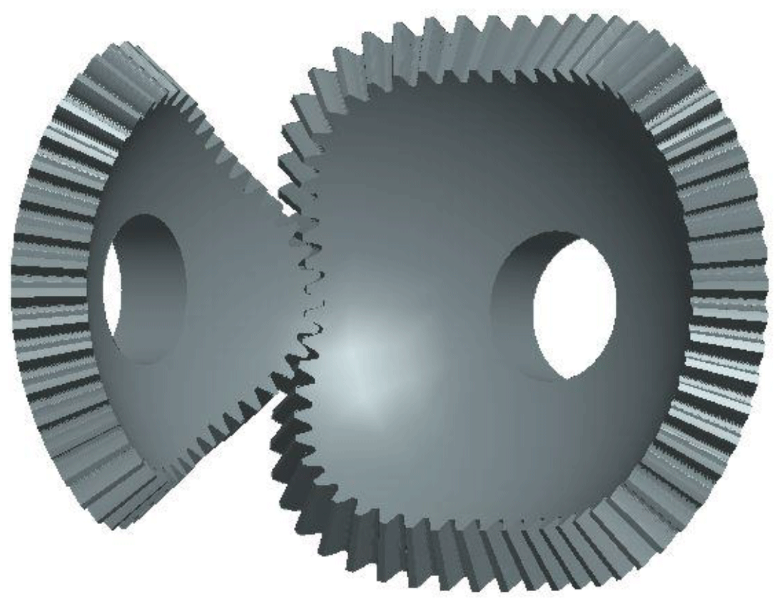
With noncircular bevel gears, power and motion can be transferred between two intersecting axes with a variable transmission executed by a suitable program of motion, as shown in Fig 1. Noncircular bevel gears combine the functions of both bevel and noncircular circular gears; in the aerospace and military fields, there will be less space for assembly and lower equipment quality. At present, noncircular bevel gears have been used in limited slip differential and gear pumps, but the application of noncircular bevel gear still needs further study. Noncircular bevel gears can be regarded as a general form of bevel gear. The research method of bevel gear is to expand the spherical pitch curves on the plane through the principle of the back cone (Huston et al., 1981, 1982, 1983). Figliolini et al. (2011) studied pitch cones for elliptical bevel gears. A general mathematical model of noncircular bevel gear is established by Lin (2012). Shi et al. (2012) present a method for designing pitch curves in a space coordinate system and machining noncircular bevel gears by using a bevel gear cutter, pitch curves and base curves, and the addendum and dedendum curves of parametric equations are established (Shi et al., 2020a, b). Jia et al. (2008a, b) reflected the spherical pitch curve to the plane, introduced the concepts of equivalent tooth shape and equivalent pitch curve, and simplified the space problem to the plane. A kind of varying-coefficient profile-shift modification method for a high-order involute of the noncircular bevel gear drive is presented, and the mathematic model for the tooth profile is established (Xia et al., 2008, 2014). A new method is presented for pitch-surface shaping (Lv et al., 2015) to shape the concave cusp or the convex cusp of the pitch surface of a multi-lobed noncircular bevel gear. Zheng et al. (2016a) proposed a universal method that is applicable to free-form the tooth profile and curvilinear tooth lengthwise. Zheng et al. (2016b) presented a face-milling method for generation of noncircular spiral bevel gears. Based on vector coordinate transmission, a new design method is proposed to simplify the calculation process of the tooth profile; as well as this, a new hot forging process is proposed to manufacture the noncircular bevel gears (Zhuang et al., 2017). In order to drive the gears continuously, it is necessary to ensure that when the former pair of gear comes out of engagement, the latter one comes into engagement, so the condition of continuous transmission of gear should meet the contact ratio ε≥1. Xu et al. (2018) studied the tooth profile design principle and method of a new type of internal gearing transmission with a large contact ratio. Gui et al. (2018) adopted a more accurate Hertz contact stiffness calculation method of tooth surface to construct its deformation coordination equation. Based on AutoCAD redevelopment by the VB program, Zhang (2018) discuss profile modification gear and the calculation method of its transverse contact ratio. At present, noncircular bevel gears are mainly processed by linear cutting and six-axis CNC machine tools, but there are still difficulties in machining.
At present, the research on noncircular bevel gears is mainly from space projection to plane, and the plane analysis is done. The innovation of our research lies in that we directly study in space, which eliminates the error caused by projection. By using the spherical cosine theorem and Napier rules, the relation of each side and angle can be derived in the space polar coordinate system, and the contact ratio can be obtained through mathematical derivation.
2.1 The contact ratio is calculated by the rotation angle
Figure 2 shows the meshing process of a pair of noncircular bevel gear pairs. In the meshing process of a pair of noncircular bevel gears, the instantaneous center P moves back and forth on the large spherical arc between two rotating axes.
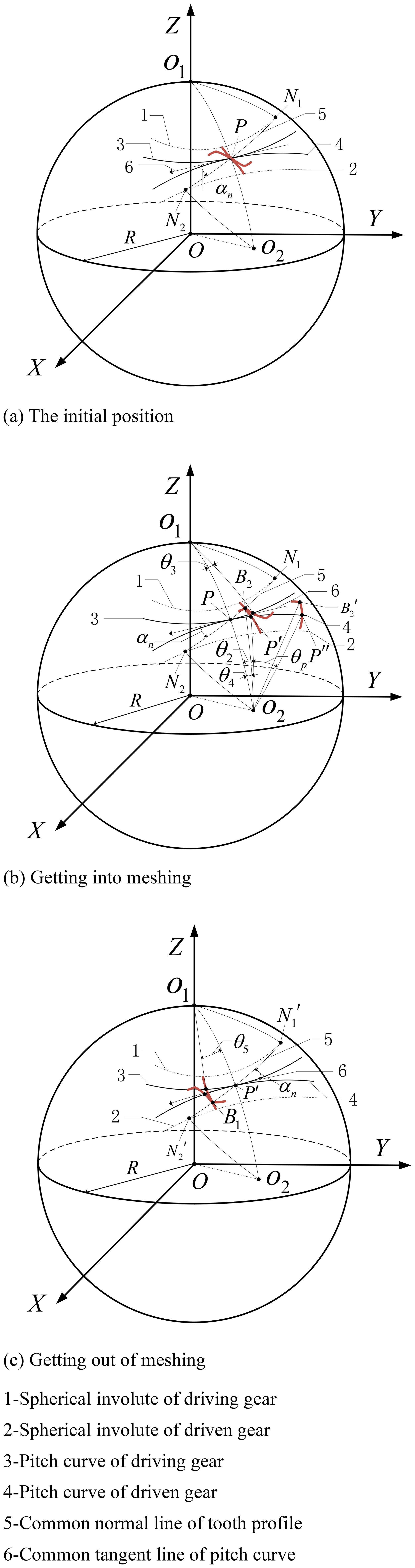
As shown in Fig. 2b the driven gear rotates clockwise from its initial position to perigon θ2, and therefore
Because the pitch curve length that both gears have rolled is S2, the angle θ3 of the driving gear rotation can be obtained:
As shown in Fig. 2c the driving gear rotates clockwise from its initial position to perigon θ5, the arc length of the pitch curve rolling is S1, and
According to the Eqs. (1)–(3), in the whole meshing process, the driving gear rotation angle is
If , it indicates that the next pair of gears has entered engagement while the previous pair of gears has not yet left engagement, and the gear pairs can continuously drive. Therefore, the contact ratio can be expressed as follows:
where θp′ is the rotation angle of the driving gear when the next tooth of the driving gear enters engagement, and . θp is the central angle of the driving gear pitch
where the angle φ1 and φ2 is the polar angle of the driving gear and the driven gear respectively. The angle φ0 is the rotation angle between the two axes of rotation, so . The angles γa1 and γa2 are the addendum curve polar angle of driving and driven gear respectively. The angle δ1 and δ2 is the tangent azimuth angle of the pitch curve of the driving and driven gear respectively. The angle αn is the tool tooth profile angle. The perigons of the pitch curve at the initial position are θp1 and θp2 respectively.
2.2 The contact ratio is calculated by the arc length
Assume that the initial position of the gear is the same, according to Eq. (1); when γa2 of driven gears is known, θ2 is calculated using the spherical arc length formula . Because the two gears do pure rolling, the arc length of pitch curve driving gear rolling is S2 too. According to Eq. (3), arc length S1 can be obtained, and the contact ratio can be expressed as follows:
where , is the arc length of the pitch curve when the next gear tooth of the driving gear enters the engagement, , Sp is the tooth space of the driving gear, , Sing(en) is the length of driving (driven) gear pitch curve, and Zing(en) is the number of teeth of driving (driven) gear.
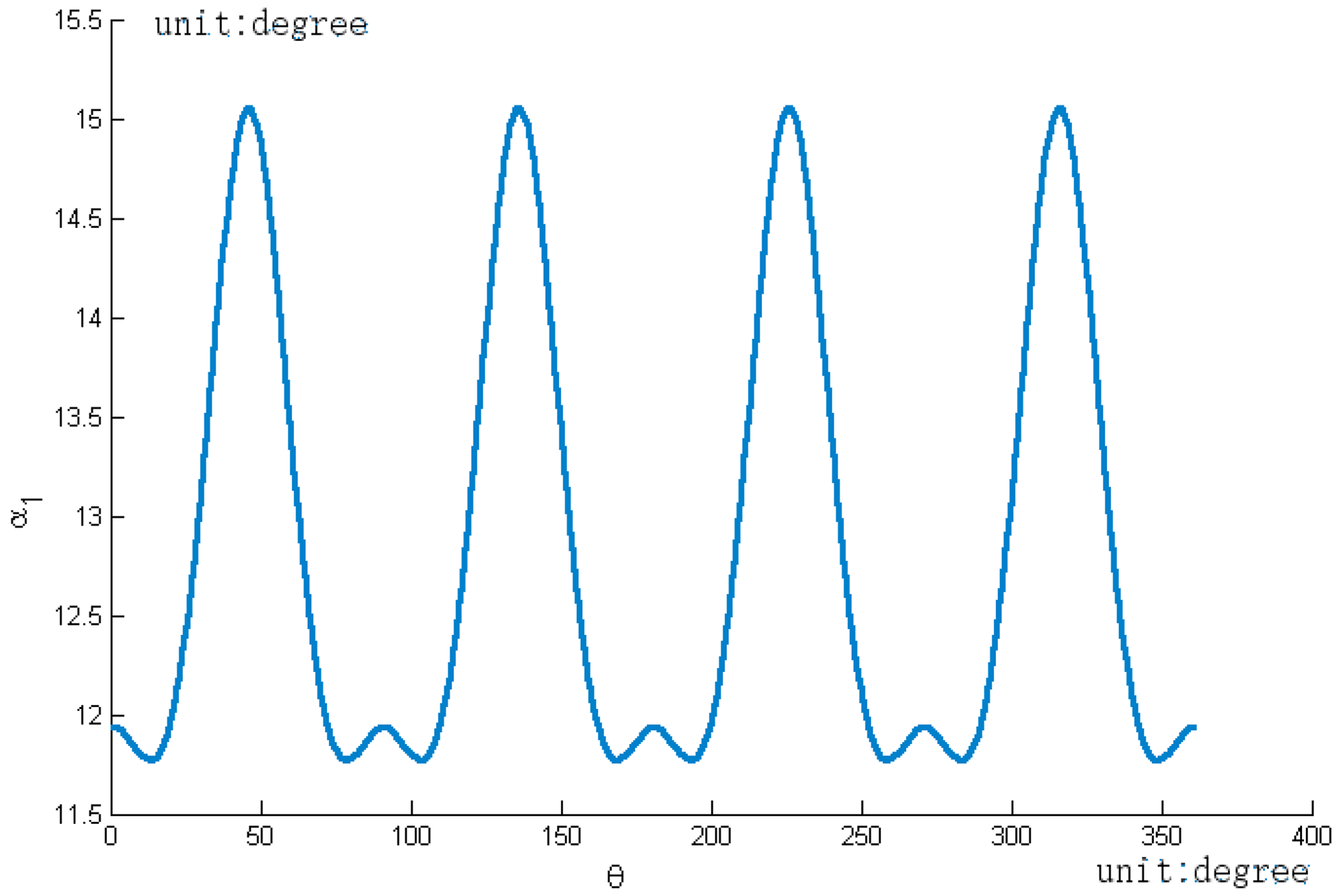
The value range of α1 can be obtained from Eqs. (1)–(3), the rotation angle α1 of the tooth profile meshing changes periodically between its top and waist, and its change range is shown in Fig. 5.
3.1 The maximum and minimum positions of the contact ratio
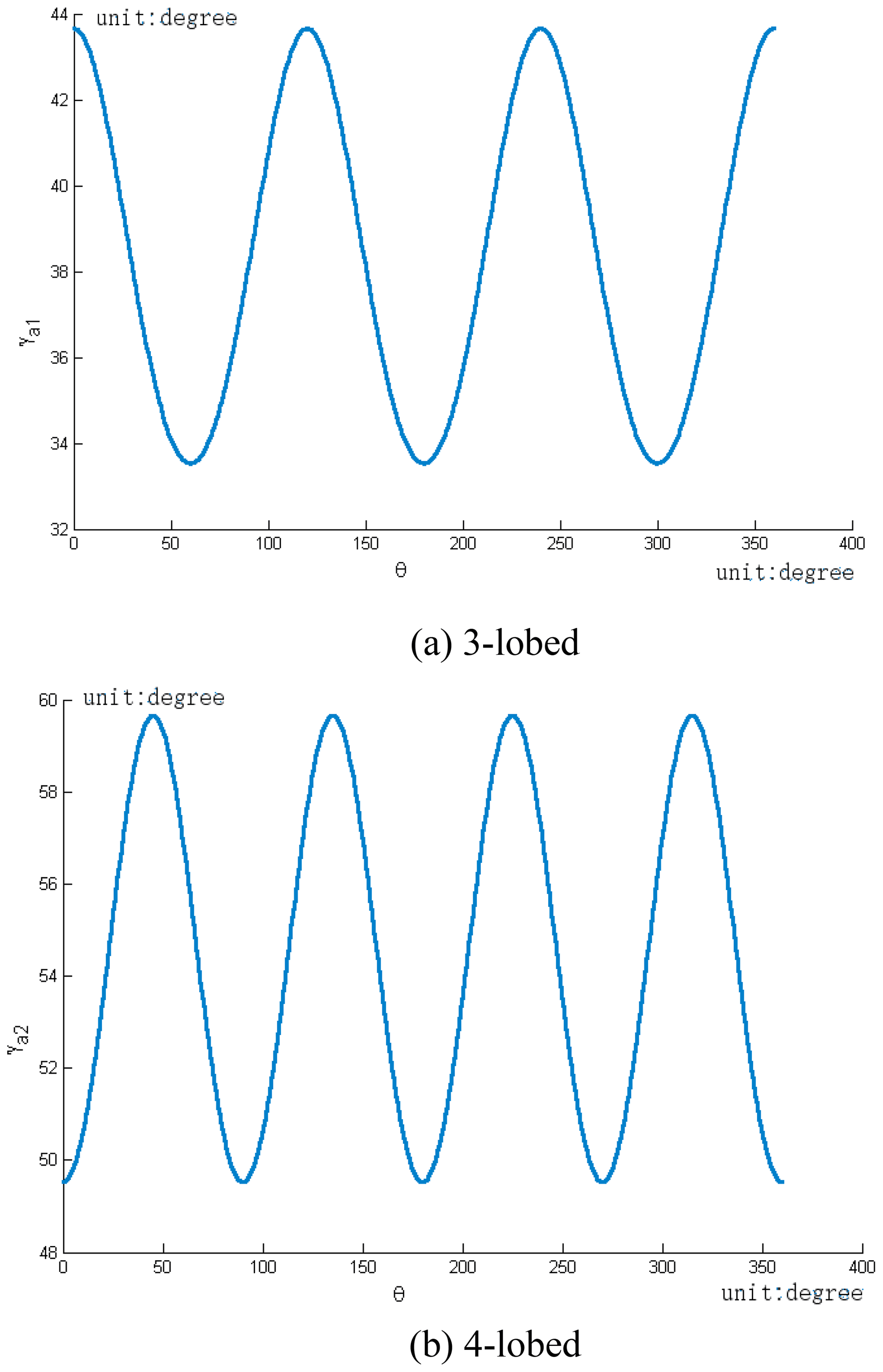
Assume that the length λ of the long axis of the noncircular bevel gear is equal to 74∘, and the intersection angle φ0 between the two rotating axes is equal to 90∘. When the tooth number Z1 and Z2 of the third-order (driving gear) and the fourth-order (driven gear) noncircular bevel gears are equal to 45 and 60 respectively, the calculation methods of the contact ratio are as follows.
Because the addendum curve is the normal equidistant curve of pitch curve, as shown in Fig. 3, the polar angle γa1 of the addendum curve changes rule with the perigon θ.
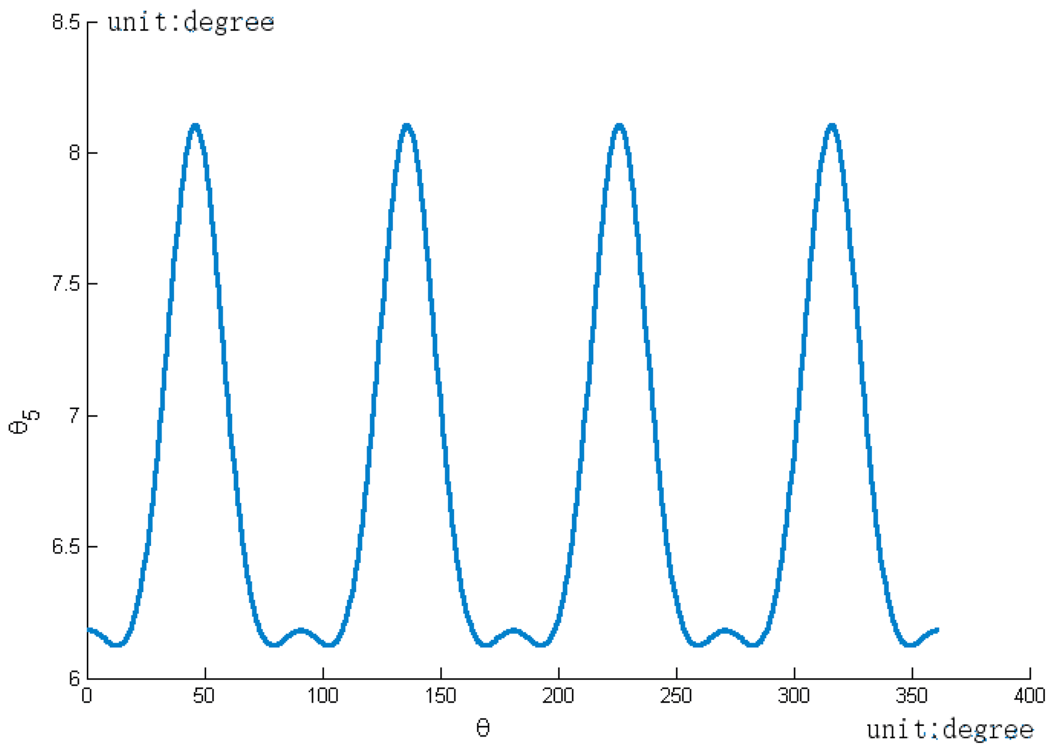
The value range of θ5 can be obtained from Eq. (3). The change rule of θ5 with the perigon θ of pitch curve of the driven gear is shown in Fig. 4.
3.2 Value range of the contact ratio
Tooth space . For the sake of illustration, θp=8. Using Figs. 3–5, the maximum of rotation angle α1 occurs when the waist of the driving gear engages with the top of the driven gear. The driving gear maximum and minimum of the rotation angle are and . In this time, the position of the driving gear is located at the perigon is equal to , the position of the driving gear located at the perigon is equal to . Therefore, the range of the contact ratio ε is 1.47–1.88.
It indicates that when one pair of teeth of this pair of noncircular bevel gears is out of engagement, the next pair of adjacent teeth has entered into engagement, and this pair of noncircular bevel gears can be continuously driven. The profile distribution of noncircular bevel gears affects their contact ratio; at the same time, the contact ratio is related to the polar angle of pitch curve. When a pair of noncircular bevel gears meshed, in order to get a better contact ratio, the tooth groove should be designed where the polar angle of the pitch curve of the gear pair is large, and the gear tooth is designed where the polar angle is small.
Noncircular bevel gear pairs with the third-order 9-tooth driving gear and the fourth-order 12-tooth driven gear is analyzed whether the pair of gears can continuously drive, and the contact ratio of each pair of teeth in meshing process is calculated respectively.
4.1 Continuous transmission
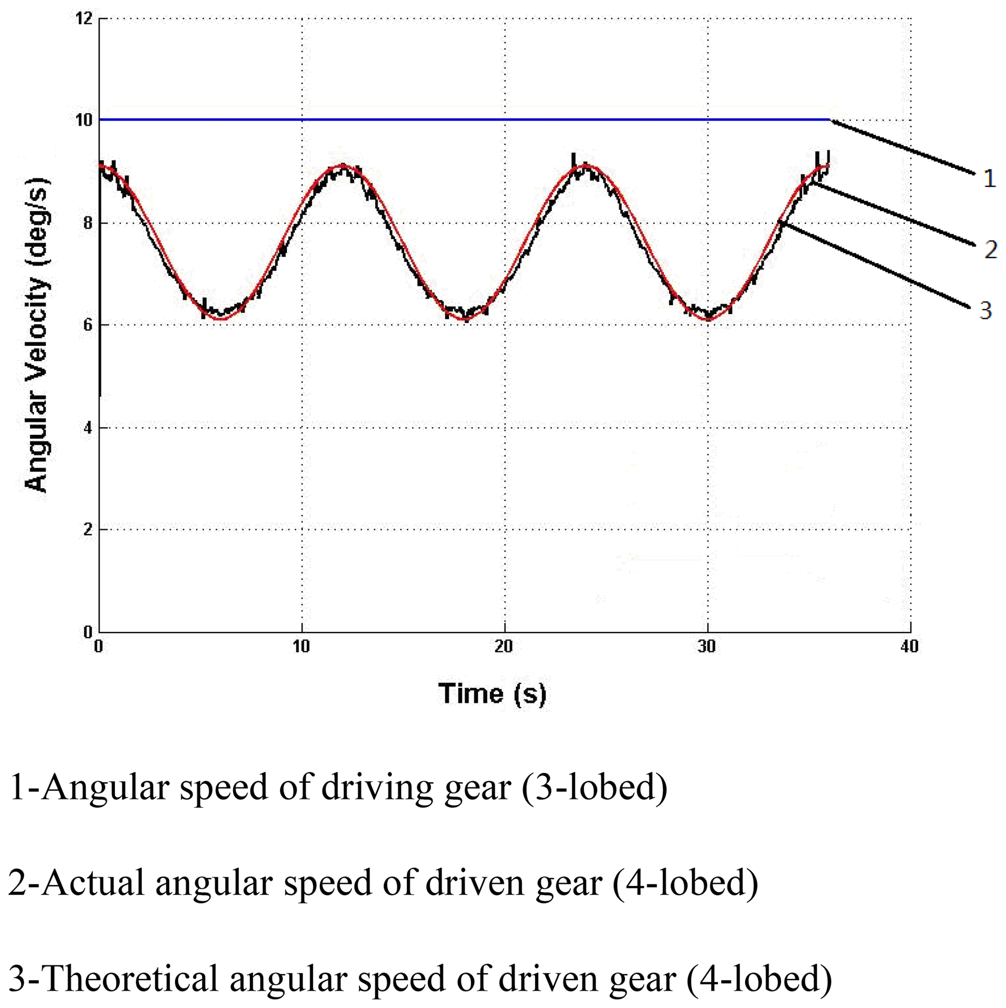
In a pair of noncircular bevel gear pairs in meshing transmission, the angular velocity of the driving gear is a fixed value, so the angular velocity of the driven gear can reflect the transmission ratio. In the ADAMS simulation, the material is set as steel, and a motor is applied to the axis of the third-order driving gear. The transmission ratio curve obtained by the ADAMS simulation and the comparison between simulation value and theoretical value are shown in Fig. 6.
On the whole, the transmission ratio curve obtained by simulation is consistent with the transmission ratio curve to be realized, and the transmission ratio curve is continuous. The driving gear rotates for one cycle, the transmission ratio changes for three periods, which proves that this gear pair can continuously drive.
4.2 Analysis of the contact ratio
4.2.1 Calculation of perigon at the intersection of pitch curve and tooth profile
Using the arc length formula of the spherical curve, the perigon at the intersection of a group of pitch curves and tooth profile curves is calculated, as shown in Fig. 7.
4.2.2 Curve model generated by tooth profile equation
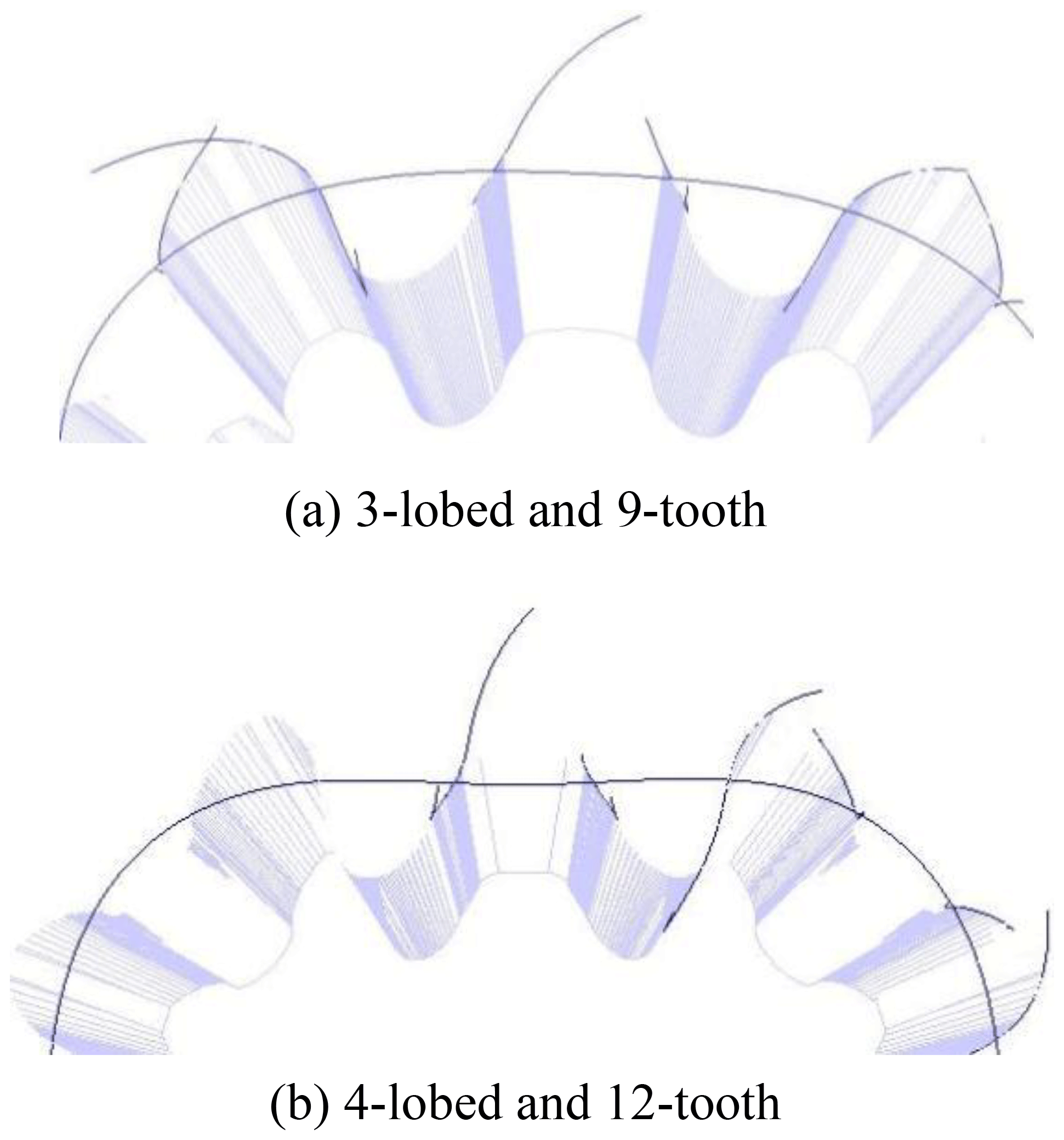
The tooth profile curve model generated by the tooth profile equation is shown in Fig. 8 (Shi et al., 2020a, b). The turning point of tooth profile curve below pitch curve is the limit position point of undercutting.
4.2.3 The polar angle at the intersection of addendum curve and tooth profile
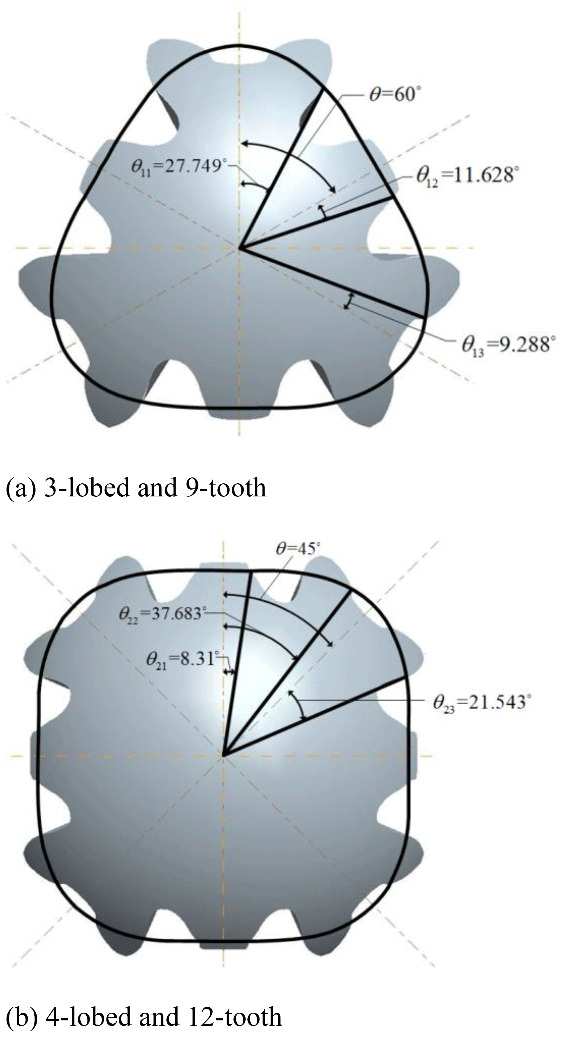
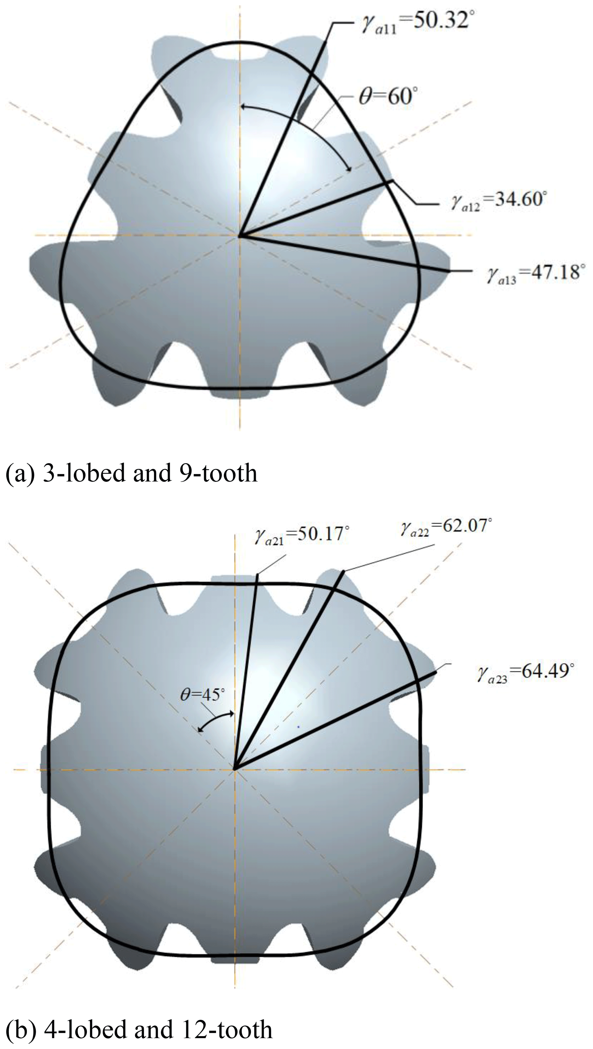
The polar angle at the intersection of the addendum curve and the tooth profile curve of the three adjacent teeth of 3-lobed and 9-tooth (4-lobed and 12-tooth) noncircular bevel gear is shown in Fig. 9.
4.2.4 Calculation of the contact ratio
The contact ratio was calculated as follows:
-
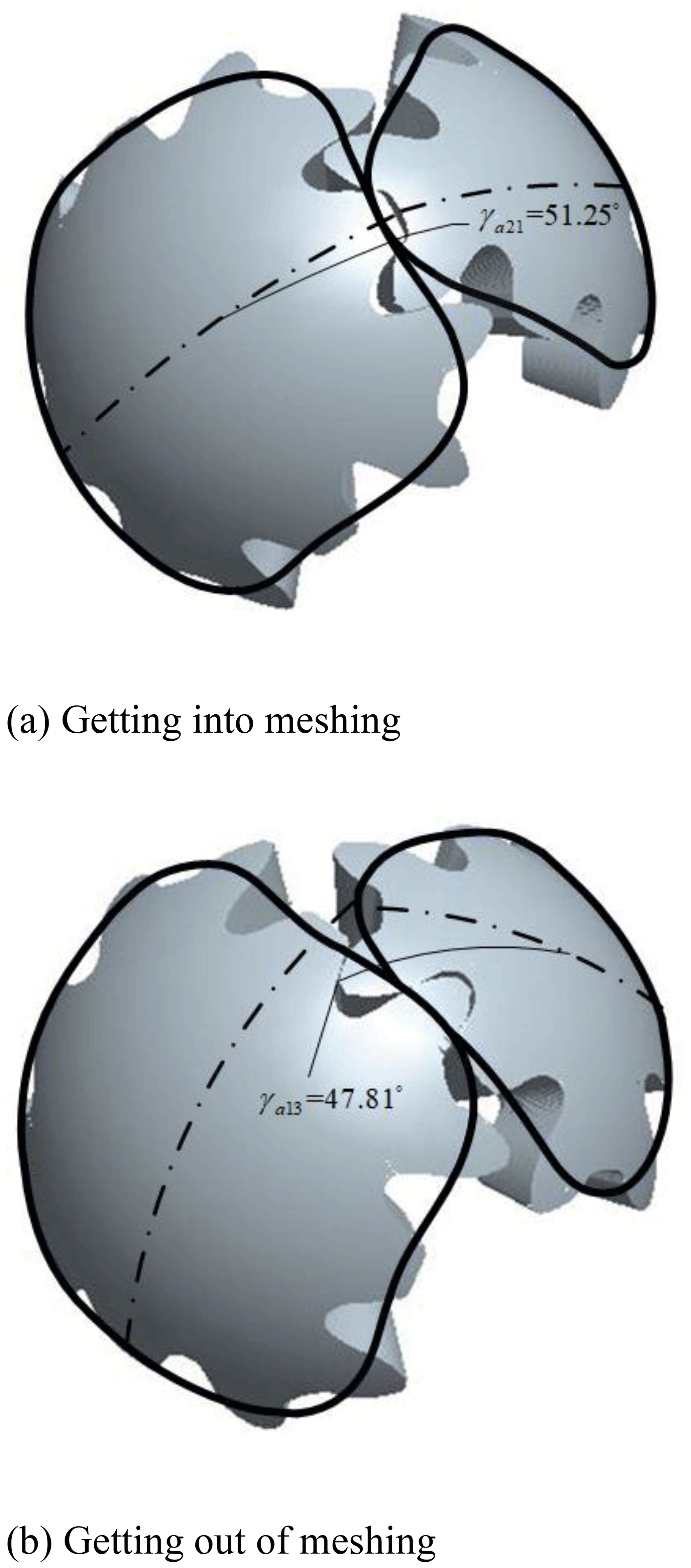
The upper-right long-tooth profile and the lower-right short-tooth profile of the driving gear meshes with the upper-right short-tooth profile + the lower-right long-tooth profile of the driven gear. The meshing process is shown in Fig. 10.
As shown in Fig. 2, the initial position remains unchanged, and the polar angle γa21 at the intersection of the tooth top line and the tooth profile is equal to 50.17∘ when the tooth profile of the driven gear begins to enter meshing. According to Eq. (1), the rotation angle θγ21 of the tooth profile of the driven gear from the initial position to the position when the tooth top enters engagement is equal to 8.28∘. At this time, the polar angle γa13 at the intersection of tooth-profile and tooth-top curves with the driving gear meshing is equal to 47.18∘. Similarly, according to Eqs. (2)–(3), the rotation angle θγa13 of the tooth profile of the driving gear from the initial position to the position when the tooth top is out of the engagement is equal to 24.84∘; at this time, the rotation angle is equal to 19.8∘ when the driven gear turns the same arc length. According to Eq. (4), the rotation angle of the driven gear in this process is . At this point, the rotation angle of the next tooth of the driven gear into mesh is equal to 21.453∘, and it satisfies the condition of continuous transmission. According to Eq. (5), the contact ratio ε is equal to 1.31.
-
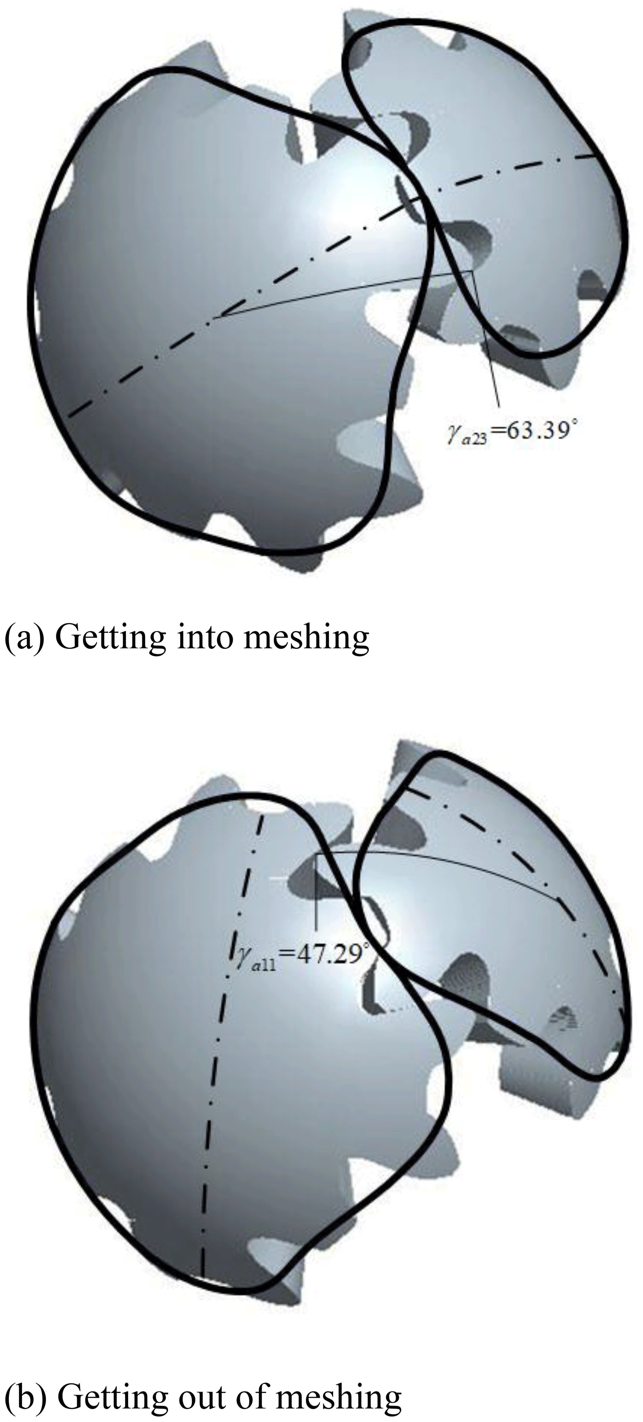
The upper-right short-tooth profile and the lower-right long-tooth profile of the driving gear engages with the upper-right long-tooth profile and the lower-right short-tooth profile of the driven gear. This engagement process is shown in Fig. 11.
As shown in Fig. 2, the initial position remains unchanged, according to Eqs. (1)–(5), and the contact ratio ε is equal to 1.01.
-
The upper-right long-tooth profile and the lower-right long-tooth profile of the driving gear engages with the upper-right long-tooth profile and the lower-right long-tooth profile of the driven gear. The meshing process is shown in Fig. 12.

As shown in Fig. 2, the initial position remains unchanged, according to Eqs. (1)–(5), and the contact ratio ε is equal to 1.01.
To sum up, for the third-order 9-tooth and the fourth-order 12-tooth noncircular bevel gear pairs, the noncircular bevel gear with fewer teeth after addendum modification avoids undercutting, and the contact ratio is greater than 1, satisfying the condition of continuous transmission. When the tooth with a short-tooth profile meshes, the rotation angle in the meshing process is smaller, while when the tooth with a long-tooth profile meshes, the rotation angle in the meshing process is larger.
In this paper, which investigates the fact that the meshing line of noncircular bevel gears is not a fixed straight line, a calculation method for the contact ratio of a pair of noncircular bevel gears in the meshing process is proposed, and the contact ratio of noncircular bevel gears in the transmission process is calculated. The conclusions are as follows:
-
The parametric equations of the contact ratio are established in the space polar coordinate system. Two innovative methods are proposed to analyze the contact ratio by using the rotation angle of the driving (driven) gears and the arc length of pitch curve as pure rolling.
-
In the case of modified gear and X-zero gear, whether the noncircular bevel gear is continuously driven is deduced. The simulation transmission ratio curve and theoretical transmission ratio curve are compared to verify the rationality of the design.
No data sets were used in this article.
The supplement related to this article is available online at: https://doi.org/10.5194/ms-12-165-2021-supplement.
SL and KS wrote the whole paper. KS and YY designed the experiment and dealt with data.
The authors declare that they have no conflict of interest.
This paper was edited by Francisco Romero and reviewed by two anonymous referees.
Figliolini, G. and Angeles, J.: Synthesis of the Pitch Cones of N-Lobed Elliptical Bevel Gears, ASME J. Mech. Des., 133, 031002, https://doi.org/10.1115/1.4003412, 2011.
Gui, X. C., Li, L. S., Li, H. X., Zhan, J. Q., and Xue, X. D.: Time-varying Mesh Stiffness Calculation and Load Distribution among Teeth of Cycloid Internal Gear Pair with High Contact Ratio, J. Mech. Eng., 54, 101–112, https://doi.org/10.3901/JME.2018.21.101, 2018.
Huston, R. L. and Coy, J. J.: Ideal Spiral Bevel Gears-A New Approach to Surface Geometry, ASME J. Mech. Des., 101, 127–133, https://doi.org/10.1115/1.3254845, 1981.
Huston, R. L. and Coy, J. J.: Surface Geometry of Circular Cut Spiral Bevel Gears, ASME J. Mech. Des., 104, 743–748, https://doi.org/10.1115/1.3256421, 1982.
Huston, R. L. and Coy, J. J.: Tooth Profile Analysis of Circular-Cut, Spiral-Bevel Gears, ASME J. Mech. Des., 105, 132–137, https://doi.org/10.1115/1.3267333, 1983.
Jia, J. M., Go, B., and Zhao, D. L.: Analysis method for noncircular bevel gearing base on geodesic curvature preserving mapping, Chin. J. Mech. Eng., 44, 53–57, https://doi.org/10.3901/JME.2008.04.053, 2008a.
Jia, J. M., Go, B., and Zhao, D. L.: Principle and method of noncircular bevel gear wire cutting, Chinese University Technology Transfer, S3, 208–210, https://doi.org/10.16209/j.cnki.cust.2006.s3.096, 2008b.
Lin, J.: Tooth Surface Generation and Geometric Properties of Straight Noncircular Bevel Gears, J. Mech. Des., 134, 084503-1, https://doi.org/10.1115/1.4006998, 2012.
Lv, G., Fan, S. W., and Zhang, X.: Study on the design and the shaping of the pitch surface of a multi-lobed non-circular bevel gear, J. Automob. Eng., 230, 542–553, https://doi.org/10.1177/0954407015589885, 2015.
Shi, K., Xia, J. Q., and Wang, C. J.: Design of noncircular bevel gear with concave pitch curve, P. I. Mech. Eng. C-J. Mec., 227, 542–553, https://doi.org/10.1177/0954406212464851, 2012.
Shi, K., Yao, Y. A., and Lin, S.: Design Method for N-Lobed Noncircular Bevel Gears, Adv. Mech. Eng., 12, 1–6, https://doi.org/10.1177/1687814019897498, 2020a.
Shi, K., Yao, Y., and Lin, S.: Synthesis of the base curves for n-lobed noncircular bevel gears, Mech. Sci., 11, 251–256, https://doi.org/10.5194/ms-11-251-2020, 2020b.
Xia, J. Q., Liu, Y. Y., Geng, C. M., and Song, J. B.: Noncircular bevel gear transmission with intersecting axes, J. Mech. Des., 130, 1–7, https://doi.org/10.1115/1.2885510, 2008.
Xia, J. Q., Shi, K., and Wang, C. J.: High–order involute modified noncircular bevel gears, J. Adv. Mech. Des. Syst. Manuf., 8, 14-00048, https://doi.org/10.1299/jamdsm.2014jamdsm0019, 2014.
Xu, A. F., Jia, J. M., Gao, B., and Tian, G. C.: Study on Design and Experiment for Internal Gear Transmission with High Contact Ratio, Mech. Trans., 42, 176-180, https://doi.org/10.16578/j.issn.1004.2539.2018.06.036, 2018.
Zhang, J.: Transverse Contact Ratio Calculation of Profile Modification Gear, Mach. Des. Res., 34, 91–93, https://doi.org/10.13952/j.cnki.jofmdr.2018.0021, 2018.
Zhang, W. H., Hua, L., Han, X. H., and Zheng, F. Y.: Design and hot forging manufacturing of non-circular spur bevel gear, Int. J. Mech. Sci., 133, 129–146, https://doi.org/10.1016/j.ijmecsci.2017.08.025, 2017.
Zheng, F. Y., Hua, L., Han, X. H., and Chen, D. F.: Generation of Noncircular Bevel Gears With Free-Form Tooth Profile and Curvilinear Tooth Lengthwise, J. Mech. Des., 138, 064501-1, https://doi.org/10.1115/1.4033396, 2016a.
Zheng, F. Y., Hua, L., Chen, D. F., and Han, X. H.: Generation of Noncircular Spiral Bevel Gears by Face-Milling Method, J. Manuf. Sci. E., 138, 081013-1, https://doi.org/10.1115/1.4033045, 2016b.
- Abstract
- Introduction
- Analysis of the contact ratio of noncircular bevel gear pairs
- Calculation of the X-zero noncircular bevel gear contact ratio
- Calculation of the contact ratio of the modified noncircular bevel gear
- Conclusions
- Data availability
- Author contributions
- Competing interests
- Review statement
- References
- Supplement