the Creative Commons Attribution 4.0 License.
the Creative Commons Attribution 4.0 License.
 | 11 Feb 2021
Formation mechanism analysis and experimental investigation of single-step printing customized circuits by liquid-metal direct writing
Yan Pu Chao
Hui Cen
Yao Hui Li
Liquid-metal direct writing is a cost-effective and green technology, which is very promising for the customized fabrication of flexible circuits and functional devices. However, owing to the high surface tension of metal ink, the printed circuits are prone to intermittent outflow, large forming size error, and unstable forming. The smooth flowing and conveying of liquid-metal ink are still huge challenges that need significant attention. Herein, the force mechanism of liquid-metal ink transported by ball rotation and translation of the printing head was analysed, and the wetting characteristics of liquid metal on the surface of different substrates and its influence on forming morphology were investigated. The stable output printing of gallium indium alloy (GaIn24.5) liquid metal was realized. The changing characteristics of the shape and size of the liquid-metal circuits formed under different printing speeds and writing pressures were experimentally studied. The effective process window for obtaining the best circuit quality was established. Based on this, a flexible printed circuit board and functional electronic pattern were successfully printed under the writing pressure W=1 N and printing speed F800 mm min−1. The printed lines of GaIn24.5 exhibited a smooth surface, uniform width, small size error, and ability to connect electronic components and conduct electricity. This research proposes a new technical approach for customized printing of personalized electronic circuits and has important application prospects in the future.
- Article
(7500 KB) - Full-text XML
- BibTeX
- EndNote


Flexible electronics is a new green electronic technology (Sahooa et al., 2020), wherein the organic or inorganic material electronic devices are connected with the printed circuit on a flexible, stretched, and thin plastic or metal substrate (Haining et al., 2020). Compared to the traditional rigid electronics, flexible alternatives offer excellent features including bending, stretching, and folding, and its process characteristics include lightweight design and inexpensive components with no risk of pollution (Mingyu et al., 2018; Jeongwoo et al., 2017). The fabricated flexible sensor, circuit board, antenna, display, and battery have a broad range of application prospects in the field of information, energy, medicine, and defence (Kenry and Lim, 2016; Guo et al., 2019; Lou et al., 2017). Especially with the future needs of flexible robots and wearable devices, it is particularly important to explore future directions for the manufacturing technology of flexible devices (Wang et al., 2018; Wehner et al., 2016). At present, the research on the manufacturing technology of flexible electronics mainly focuses on the two aspects including preparation of conductive functional materials and the manufacture process of flexible circuit, at the global scale. In the preparation of flexible electronic conductive functional materials, the current research mainly focuses on the water-soluble conductive ink (Qin et al., 2017a), nano conductive silver pulp (Qin et al., 2017b), and liquid metal (Chang et al., 2018). The water-soluble conductive ink offers the advantages of simple manufacturing process and cost effectiveness. However, its conductivity at room temperature is much lower compared to that of the metal material. The service life of a dried connection circuit is limited after bending, which thus easily disconnects and loses its electrical conductivity. Moreover, the fabricated circuits do not have the tensile properties. In contrast, nano conductive silver pulp significantly improves the conductivity compared to the water-soluble conductive ink; thus, the flexible circuit can be successfully printed using nano conductive silver pulp. Nonetheless, the preparation process of nano conductive silver pulp is complex, the ink is expensive, and the printed circuits are required for the subsequent processing of high sintering processes (Wei et al., 2014). Most flexible material substrates require a post-treatment temperature of below 150 ∘C; therefore, the structures of flexible material are easily destroyed under the excessive temperature. As a result, the applicability of nano conductive silver pulp is inhibited, rendering it unsuitable as a type of universal flexible electronic conductive material. Liquid metal is an alloy based on gallium or bismuth, which is liquid at room temperature and has strong conductivity and high thermal conductivity. It mainly includes gallium indium alloy (EGaIn) and gallium indium tin alloy (Galinstan). The preparation process of liquid metal is simple, friendly, and non-toxic to the environment. A circuit can be directly printed at room temperature without subsequent treatment (Yang and Liu, 2014). The printed circuit can maintain stable performance for a long time. Many technical bottlenecks, such as low conductivity of ink in traditional printing electronic technology, complex synthesis and preparation technology, and requirement of sintering, have been overcome by using liquid-metal ink. Thus, the fabrication process of a flexible circuit becomes simpler.
In terms of flexible circuit manufacturing technology, the main methods include the micro-channel injection method, spraying printing method, and direct-writing printing method. In the process of preparing a flexible circuit by micro-channel injection, the inner part of the micro-channel is first fabricated by lithography, and then the liquid metal is filled into the micro-channel to form a conduction circuit (Flowers et al., 2017). The liquid metal maintains a good fluidity in the micro-channel; therefore, the material can be bent or stretched without changing its electrical properties. However, the process of making micro-channels in the interior part is relatively complicated, and the air easily enters during the liquid-metal filling process, resulting in breaking of local circuit. Therefore, it is unsuitable for fabricating large-sized electronic devices.
The high-pressure spraying and mask technique is used in the spraying printing process (Zhang et al., 2014). Liquid metal is dispersed into smaller droplets under the shear action of high velocity airflow and the sheet of metal, paper, or other materials is fabricated into mask. Under the cover of the mask, discrete liquid-metal micro-droplets are hit, which get adhered to the substrate to form the required circuit structure. The same mask template can be used several times, thus making the process suitable for mass production. However, design of each new circuit requires the preparation of the corresponding new mask template, which makes the process expensive and time consuming.
The direct-writing printing technology can directly print the liquid-metal circuit on the surface of various flexible matrix materials, and the function of electronic components connection and electricity conduction can be acquired. This method involves the characteristics of a simple process, cost effectiveness, and high efficiency, which are suitable for the rapid printing of personalized electronic circuits. In recent years, it has become a research hot spot for researchers at home and abroad.
Gao et al. (2012) used a simple brush as tool to directly print the liquid-metal (GaIn10) circuit on the surface of epoxy resin, glass, plastic, silicone, paper, cloth, and so on at room temperature for the first time. The printed liquid metal could adhere well to the surface of the substrate. However, the line width of the printed circuit was 2 mm, and the accuracy of the printed liquid-metal line was relatively low. Zheng et al. (2013) proposed a novel method of printing liquid-metal circuits and functional devices on coated paper using a desktop printer. The liquid metal (GaIn10) was stored in syringe, and it was extruded from a brush under the action of nitrogen pressure. The electronic circuit and radio frequency identification antenna were successfully printed on coated paper by controlling the printing height and speed. The line width of the printed circuit was 1.5 mm, and the conductive stability of the liquid gallium indium alloy was thus confirmed. However, the edge of the printed circuit was not smooth enough and the resolution was low. William et al. (2014) made use of the high-adhesion behaviour between a gallium indium alloy and silicon-based material, and the gallium indium alloy was successfully printed on polydimethylsiloxane (PDMS) and glass. Zheng et al. (2014) proposed liquid-metal automatic composite printing technology based on the writing principle of a ball. The basic mechanism of reliable printing, transfer, and adhesion of liquid metal on substrate was theoretically analysed. A series of representative electronic patterns spanning from single wires to desired complex configurations such as an integrated circuit, electronic paintings, and functional electronic pattern was printed.
Based on the adhesion mechanism of liquid metal on different substrates, Guo et al. (2018) proposed an efficient flexible electronic preparation technology for liquid-metal paper-based transfer printing. Its feasibility was explored in flexible electronics, paper-based robots, and other fields. In short, the above-mentioned printing methods realized the printing of the liquid-metal circuit on the flexible substrate. However, owing to the low viscosity and high surface tension characteristics of liquid-metal ink, technical problems including intermittent outflow, larger forming size error, and forming instability are easily encountered in the printing process of the liquid metal. Therefore, it is necessary to systematically explore the influence of technological parameters (such as substrate wetting ability, printing speed, printing pressure, and so on) on forming accuracy and quality.
In this study, the force mechanism of liquid-metal ink transported by ball rotation and translation of a printing head was analysed. The changing characteristics of shape and size of the liquid-metal circuit formed under surfaces of different substrates, printing speeds, and pressures were studied through experiments. Based on this, the flexible complex circuit and functional electronic pattern were printed. This research proposes a new technical approach for customized printing of personalized electronic circuits and has important application prospects in the future.
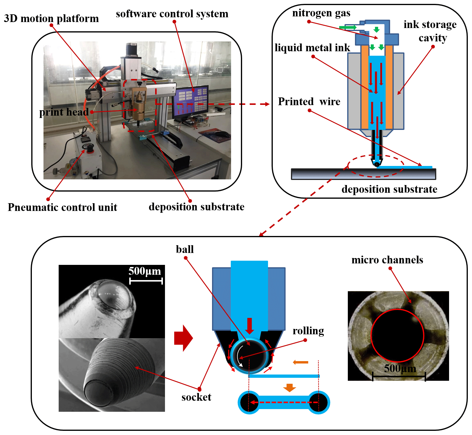
Figure 1 shows a schematic illustration of the process principle and experimental set-up of liquid-metal ink direct printing. The forming principle of liquid-metal ink direct printing is as follows: the ball of the print head is driven to roll in the ball socket under the action of horizontal thrust and comprehensive friction force when the ball contacts the printing substrate surface (polyvinyl chloride (PVC), polyethylene (PE), etc.) to the print circuit. Furthermore, the liquid-metal ink in micro-channels is carried out by the rolling ball, which then adheres to the surface of the printed material to form a circuit. The comprehensive friction force is the sum of the sliding friction between the ball in the printing head and the inner surface of the ball socket and the rolling friction between the ball in the printing head and the printing surface. In order to ensure the normal working of the printing head, the following three critical conditions need to be met: (1) the friction between the ball and the printed surface should be greater than that between the ball and the inner surface of the ball socket; (2) the wetting property of liquid-metal ink on the printing surface should be higher than that on ball, and the wetting property of the ball-to-ball socket should be higher than that of the liquid-metal-ink-to-ball socket; and (3) the flow rate of liquid-metal feeding system should be larger than that of the outflow system.
Based on the above-mentioned principles, an experimental system was developed herein. The experimental system mainly included a printing head, a three-dimensional (3D) motion platform, a pneumatic control unit, a deposition substrate, and a software control system. The printing head was used to deliver and adhere the liquid-metal ink to the printing surface, which consisted of an ink storage cavity, a solenoid valve, a ball, a ball socket, a micro-channel, and a nitrogen gas resource. The liquid-metal ink was stored in the ink storage cavity. When the solenoid valve was opened, the compressed gas got filled into the ink storage cavity to maintain a constant pressure. The pressure value was set in the range of 0.01–1.00 MPa. The ball was embedded into the ball socket, and the inner surface of the ball socket consisted of several micro-channels. The 3D motion platform was used to create a circuit by controlling the movement track of the 3D platform according to data information. It consists of a multi-axis motion controller, deposition substrate, and three-axis (x, y, z) servo motors. The maximum stroke of the three-axis motion platform was 300 mm in the x direction, 300 mm in the y direction, and 200 mm in the z direction. The pneumatic control unit was composed of the air pump, pressure regulating valve, gas-pressure meter, and pipeline, which was used to provide a constant pressure in the ink storage cavity. A software control system was used as the key module of the liquid-metal ink direct printing system, which was mainly used for real-time output of various instructions and signals in order to control the action of all moving parts in the system. Further, the real-time testing data of various sensors were received, and the coordinate spacing, screw pitch, motor speed, and acceleration were set and displayed. In short, the several parts mentioned above were co-ordinately controlled to complete the printing of the circuit.
The principle of tribology indicates that there must be friction, lubrication, and wear as long as there is an interface contact. Analysis of the principle of liquid-metal ink direct printing circuits indicated the occurrence of two typical friction phenomena in the direct printing process. One is the sliding friction between the ball in the printing head and the inner surface of the ball socket due to the printing pressure, the value of which is large and accompanied by the wear generation. The second is the rolling friction between the ball in the printing head and the printing surface under the normal load of the ball on the printing surface and the horizontal thrust. The rolling friction consists of a combination of rolling, sliding, and rotating friction. Therefore, the operating procedure of a liquid-metal ink direct printing circuit is a complex process, involving the interaction and influence of sliding friction, rolling friction, and lubrication.
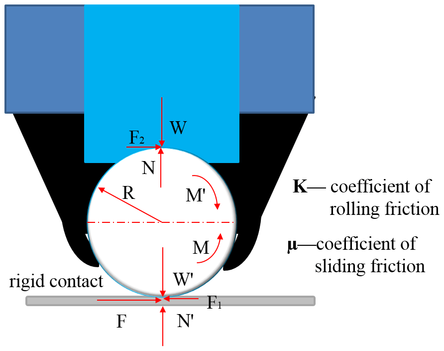
Figure 2 shows force analysis of the ball in the printing process, exhibiting that the normal load acting on the ball through the base of the ball socket of the printing head is defined as the printing pressure W. The reaction force of the ball against the ball socket is N. The normal load of the ball acting on the printing surface is W′. The reaction force of the printing surface against the ball is N′. The horizontal force F is used to make the ball move relative to the printing surface. M is the driving torque, which is applied to make the ball rotate. M′ is the resistance torque, which is used to stop the rotation of the ball. F1 is the rolling friction between the ball and the printing surface, and F2 is the sliding friction between the ball and the base of the ball socket. R is the radius of ball, K is the coefficient of the rolling friction, and μ denotes the coefficient of the sliding friction.
Therefore, the relationship of shape parameters can be expressed in terms of Eqs. (1)–(5). In the printing circuit process, the printing pressure W is transferred onto the printing surface by the ball, and the reaction force N′ of the printing surface is transferred to the ball. Furthermore, N′ is also transferred to the ball socket through the ball. Therefore, two pairs of pressure and reaction forces are generated between the ball and the base of the ball socket and between the ball and the printing surface, respectively. Owing to the horizontal force F applied at the tangential direction of the contact point between the ball and the printing surface, the radius of the ball R is used as a moment arm, and the driving torque M is formed and applied to make the ball rotate. Therefore, the relationship between them can be expressed in terms of Eq. (1).
When , the ball can be rotated, and the circuit is printed normally. The rolling friction torque M2 is generated between the sliding friction F2 and the centre of mass of the ball. The relationship between them can be expressed in terms of Eq. (2).
The printing surface is not rigid; therefore, the ball presses a pit on the printing surface under the printing pressure. The ball with a larger diameter presses into a smaller depth, while the ball with a smaller diameter presses into a larger depth. When the reaction force N′ is not in line with the normal load force W′ on the printing surface, a rolling friction torque M1 is formed to prevent rolling. The relationship between them can be expressed in terms of Eq. (3).
According to the classical tribology,
Assuming that
we can conclude that
When the material of the printing head and the lubricant remain unchanged, the rolling friction coefficient k and the sliding friction coefficient μ remain basically unchanged. The horizontal force F is only related to the radius of sphere, R, and the printing pressure W. A printing head with larger ball diameter shows a better hand feel than one with smaller ball diameter. When the printing pressure W is greater, the comprehensive friction resistance is greater and the horizontal force F is also larger.
In the process of a liquid-metal direct-writing printing flexible circuit, the ball of the printing head is driven to roll in the ball socket under the action of horizontal thrust and comprehensive friction force when the ball contacts the printed surface to print the circuit. The liquid-metal ink in micro-channels is carried out by the rolling ball, and then it gets adhered to the surface of the printed material to form a circuit.
It was observed that the wetting characteristics of liquid metal on surfaces of different printing substrates, the printing speeds, and the writing pressures are the main factors affecting the forming quality of the printing line. The changing characteristics of shape and size of liquid-metal circuits formed under different writing substrate surfaces, printing speeds, and writing pressures were experimentally studied herein. The effective process window for obtaining the best circuit quality was established. This is a necessary guarantee to realize the flexible complex circuit and functional electronic pattern.
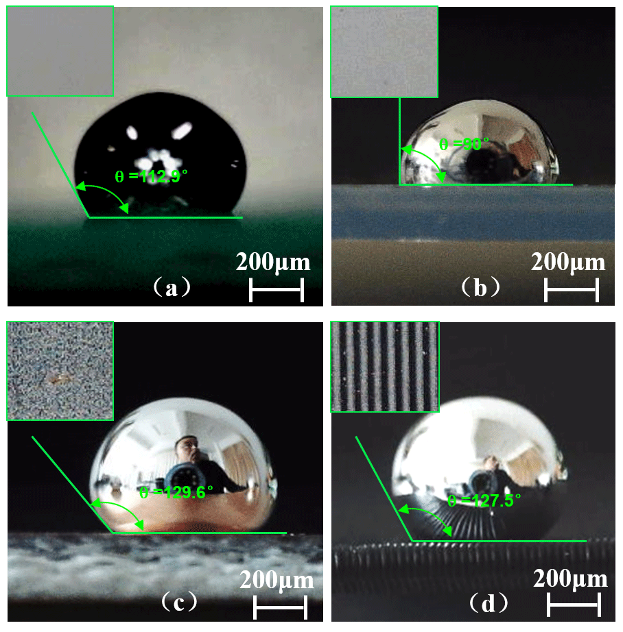
Figure 3The morphologies of liquid metal on the surface of different substrate materials: (a) glass; (b) PVC; (c) copper-clad plate; (d) ABS.
Figure 3 shows the morphological characteristics of liquid metal on the surface of different substrate materials. The gallium indium alloy (GaIn24.5) was selected as the printing material, its melting point is 15.7 ∘C, density is 6.3 g cm−3, viscosity is 0.27 Cst, surface tension is 0.60 N m−1, and the electrical conductivity is 0.348×10⁷ s m−1. The base materials are glass, PVC, copper-clad plate, and acrylonitrile butadiene styrene (ABS), respectively. According to the measurement, the wetting angles between liquid metal and four substrates were found to be 112.9, 90, 129.6, and 127.5∘, respectively. The wetting ability of PVC to liquid metal was relatively good, which exhibited greater adhesive force to PVC. It is thus advantageous to print the liquid-metal line on the surface of PVC. In contrast, the other three substrates showed little adhesion behaviour.
Figure 4 shows the 24 direct-writing printing lines under different process parameters, which are listed in Table 1, and all the samples were fabricated under writing pressure of W=1 N. The GaIn24.5 alloy was selected as printing material, the printing head was composed of a 0.5 mm diameter tungsten carbide ball and stainless steel ball seat, and the PVC films with thickness of 0.5 mm were used as a printing substrate. Different printing speeds VF were set, and the values are listed in Table 1.
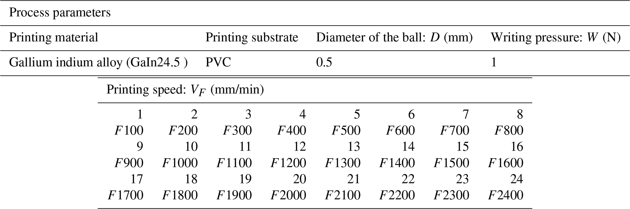
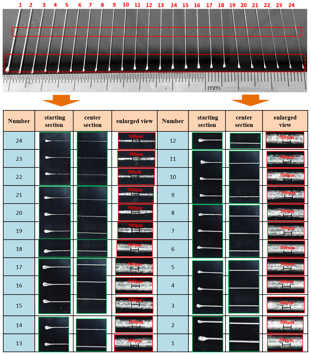
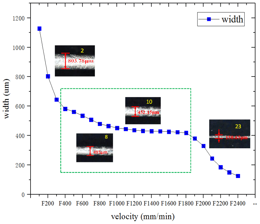
The morphology of the printing lines at each printing speed was captured using a macro lens. The starting section, centre section, and enlarged view of printing lines are shown in Fig. 4. The Image Pro software was used to measure the width of printing lines in different positions. Based on the values of the four measurements, an average value was calculated, as shown in Fig. 5. Figure 5 demonstrates that the width of the printed lines decreases with the increase in the printing speed. When the printing speed VF is set as F100, F200, F300, F400, F500, and F600, the average measured width of the forming line is 1128, 804, 645, 582, 562, and 535 µm, respectively. The line width is obviously larger than the diameter (0.5 mm) of the writing ball. When the printing speed VF is set as F700 and F800, the average measured width of the printing line is 508 and 495 µm, respectively. In this case, the line width is basically equal to the diameter (0.5 mm) of the writing ball. When the printing speed VF is set as F900, F1000, F1100, F1200, F1300, F1400, F1500, F1600, F1700, and F1800, the average measured width of the printing line is 475, 462, 445, 439, 437, 432, 429, 426, 424, and 420 µm, respectively. The line width is obviously less than the diameter (0.5 mm) of the writing ball.
Further, the width of printing line decreases rapidly. When the printing speed VF is set as F1900, F2000, F2100, F2200, F2300, and F2400, the average measured width of the printing line is 405, 324, 215, 185, 150, and 126 µm, respectively. The line width is obviously less than the diameter (0.5 mm) of the writing ball.
Figure 4 shows the local enlarged morphology of each printing line. Clearly, when the printing speed is too fast (F2300 and F2400), the width of printing line is very small, the printed line is not smooth enough, and the intermittent phenomenon of the line appears, which is unable to ensure the circuit conduction. This is mainly attributed to the fact that the speed and flow of liquid metal by the ball rotating transport cannot meet the requirement of fast liquid-metal direct-writing printing. When the printing speed is too slow (F100, F200, and F300), the width of the printing line is very large and the printing efficiency is low. The stacking and spreading phenomenon of liquid metal occurs obviously, resulting in waste of printing materials. The above-mentioned experimental analysis results indicate that the appropriate printing speed VF is between F700 and F1800. In particular, when the printing speed VF is set as F700 and F800, the width of the printing lines becomes basically equal to the diameter of the writing ball. The surface is smooth, continuous, and changes a little, which is very suitable for printing a conductive line.

In the process of liquid-metal direct-writing printing, the writing pressure W is a key factor to produce a comprehensive friction force. It is worth noting that only the writing pressure is appropriate to ensure that the ball of printing head is driven to roll in the ball socket, the liquid-metal ink in micro-channels is carried out by the rolling ball, and the liquid-metal ink is adhered to the surface of the printed material to form a circuit. The comprehensive friction force is the sum of the sliding friction between the ball in the printing head and the inner surface of the ball socket and the rolling friction between the ball in the printing head and the printing surface.
When the writing pressure is too high, the comprehensive friction resistance and the required horizontal writing force increase. As a result, the local deformation of the writing surface becomes obvious, which affects the flow and adhesion of liquid metal on the writing surface, leading to the occurrence of the phenomenon of bifurcation in the printing line. When the writing pressure is too small, the comprehensive friction resistance and the required horizontal writing force decrease. The horizontal writing force does not ensure the rolling of the ball in the ball socket. As a result, significant sliding friction is observed between the ball and the writing surface, and liquid metal cannot continuously adhere to the writing surface. The intermittent phenomenon of the line does not appear to ensure the circuit conduction.
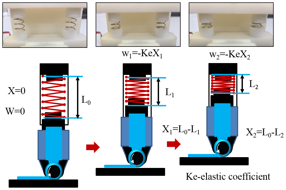
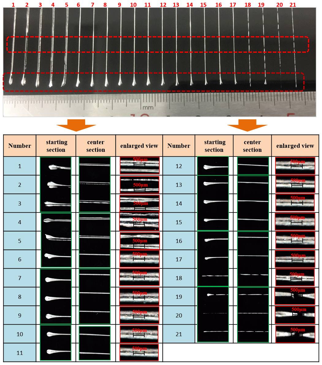
In this study, a tiny spring was used to effectively control the writing pressure, and its principle is shown in Fig. 6. The entire printing head was fixed on the connecting device with slide guide and spring. The writing pressure could be effectively controlled by controlling the compression deformation of the spring. The experimental process parameters of the 21 samples are presented in Table 2. All the samples were fabricated under VF = F800 printing speed. The GaIn24.5 alloy was selected as printing material, the printing head was composed of a 0.5 mm diameter tungsten carbide ball and stainless steel ball seat, and the PVC film with thickness of 0.5 mm was used as a printing substrate. The writing pressure W was set and the corresponding values are listed in Table 2. The morphology of the printing lines at each writing pressure was captured using a macro lens. The starting section, centre section, and enlarged view of printing lines are shown in Fig. 7. The measuring software was used to measure the width of printing lines in different positions. Based on the values of the four measurements, the average value was calculated, as shown in Fig. 8.
Figure 8 demonstrates that the width of the printed lines decreases with the decrease in the writing pressure. When the writing pressure W is set as 1.7, 1.6, 1.5, 1.4, and 1.3 N, the average measured width of the forming line is 865, 855, 835, 805, and 785 µm, respectively. The line width is obviously larger than the diameter (0.5 mm) of the writing ball. The change of line width is quite significant. When the writing pressure W is set as 1.2, 1.1, 1, 0.9, 0.8, 0.7, 0.6, 0.5, 0.4, 0.35, 0.3, 0.25, 0.2, 0.15, 0.1, and 0.05 N, the average measured width of the printing line is 480, 475.35, 462.5, 435.58, 418.5, 410.8, 380.5, 352.65, 335.5, 318.5, 295.65, 245.5, 198.6, 165.5, 155.5, and 135.2 µm, respectively. The decrease in forming size is approximately a linear change.
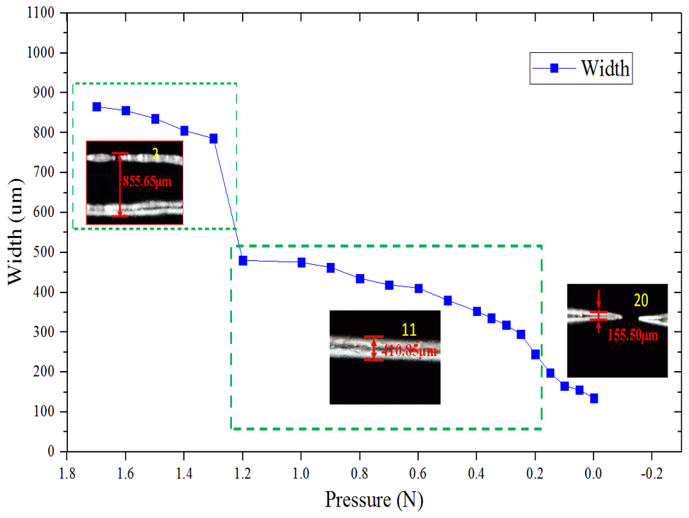
Figure 7 shows the local enlarged morphology of each printing line. When the writing pressures are too high (1.7, 1.6, 1.5, 1.4, and 1.3 N), the interior of the printing lines does not contain the liquid metal, which is adhered only at the edges of printing lines, leading to the occurrence of the phenomenon of bifurcation in the printing lines. This is mainly attributed to the extremely high writing pressure, and obvious local sag deformation of the writing surface, which affects the flow and adhesion of liquid metal on the writing surface. The liquid metal cannot be filled into the deformed region in time; thus, there is no adhesive liquid metal inside the forming line. When the writing pressures are too small (0.15, 0.1, and 0.05 N), the intermittent phenomenon of printing lines is unable to ensure the circuit conduction. This is mainly because when the writing pressure is too small, the comprehensive friction resistance and the required horizontal writing force are lower. On the one hand, the comprehensive friction resistance does not ensure the ball rolling in the ball socket, and the output flow of liquid metal is reduced. On the other hand, a significant sliding friction phenomenon occurs between the ball and the writing surface, and the liquid metal cannot continuously adhere to the writing surface, resulting in intermittent printing lines.
The above-mentioned experimental analysis results indicate that the appropriate writing pressure W is between 1.2 and 0.2 N. It can ensure that the printed conductive line is not accompanied with the appearance of internal gaps and discontinuous defects. In particular, when the writing pressure W is set as 1.2, 1, and 0.9 N, the width of the printing lines is basically equal to the diameter (0.5 mm) of the writing ball. The surface is smooth, continuous, and changes slightly, which is extremely suitable for printing conductive lines.
According to the above-mentioned research results under different writing pressures and printing speeds, the process windows for effectively providing the optimal circuit quality are obtained, as shown in Fig. 9. When the writing pressure W = 0.2–1.2 N and the printing speeds VF = F700–F1900, the printed lines do not show obvious defects. In particular, when the writing pressure W = 0.9–1.2 N and the printing speed VF is set as F700 and F800, the width of the printing lines is basically equal to the diameter of the writing ball. The surface is smooth, continuous, and changes a little, which is suitable for printing conductive lines.
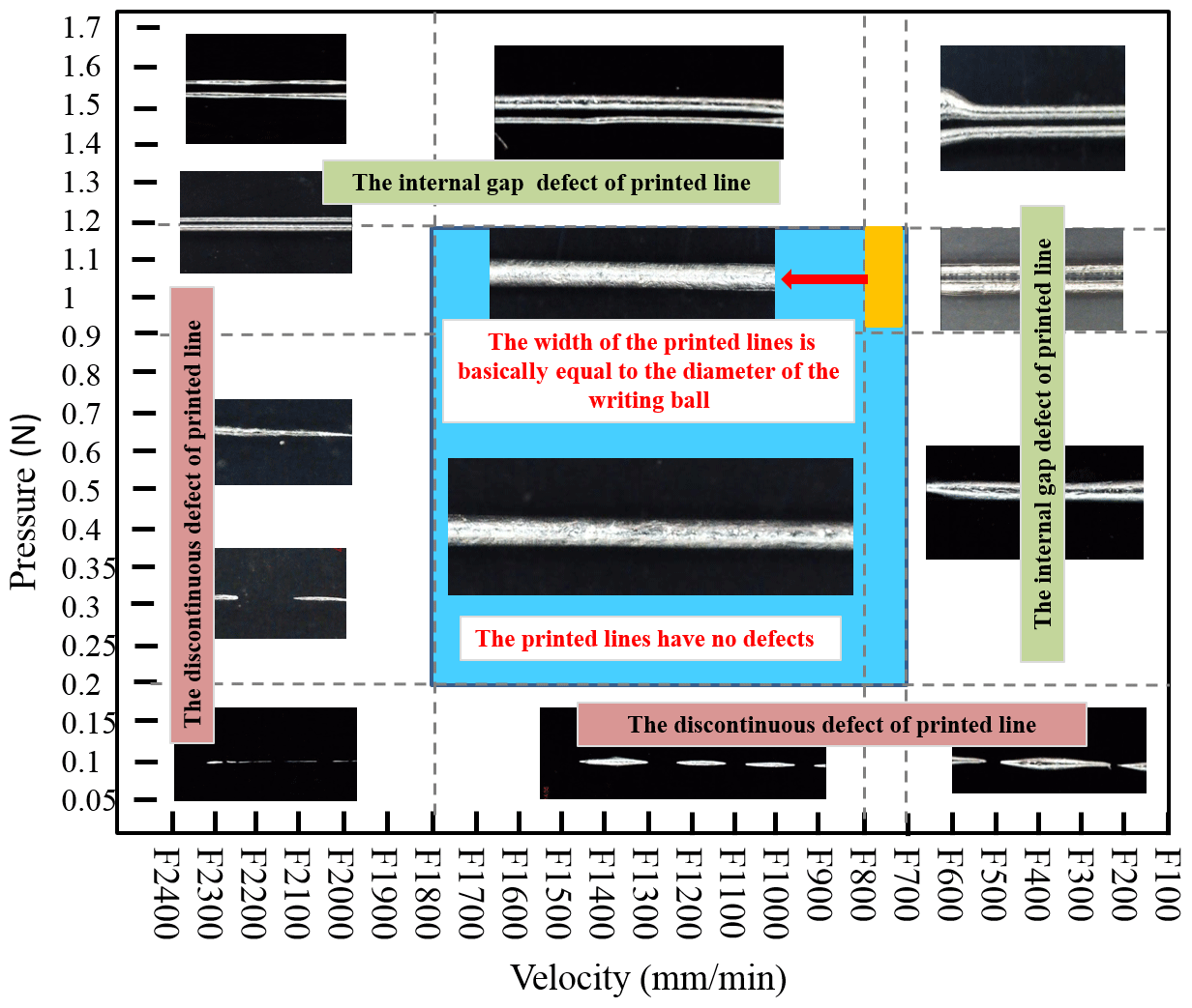
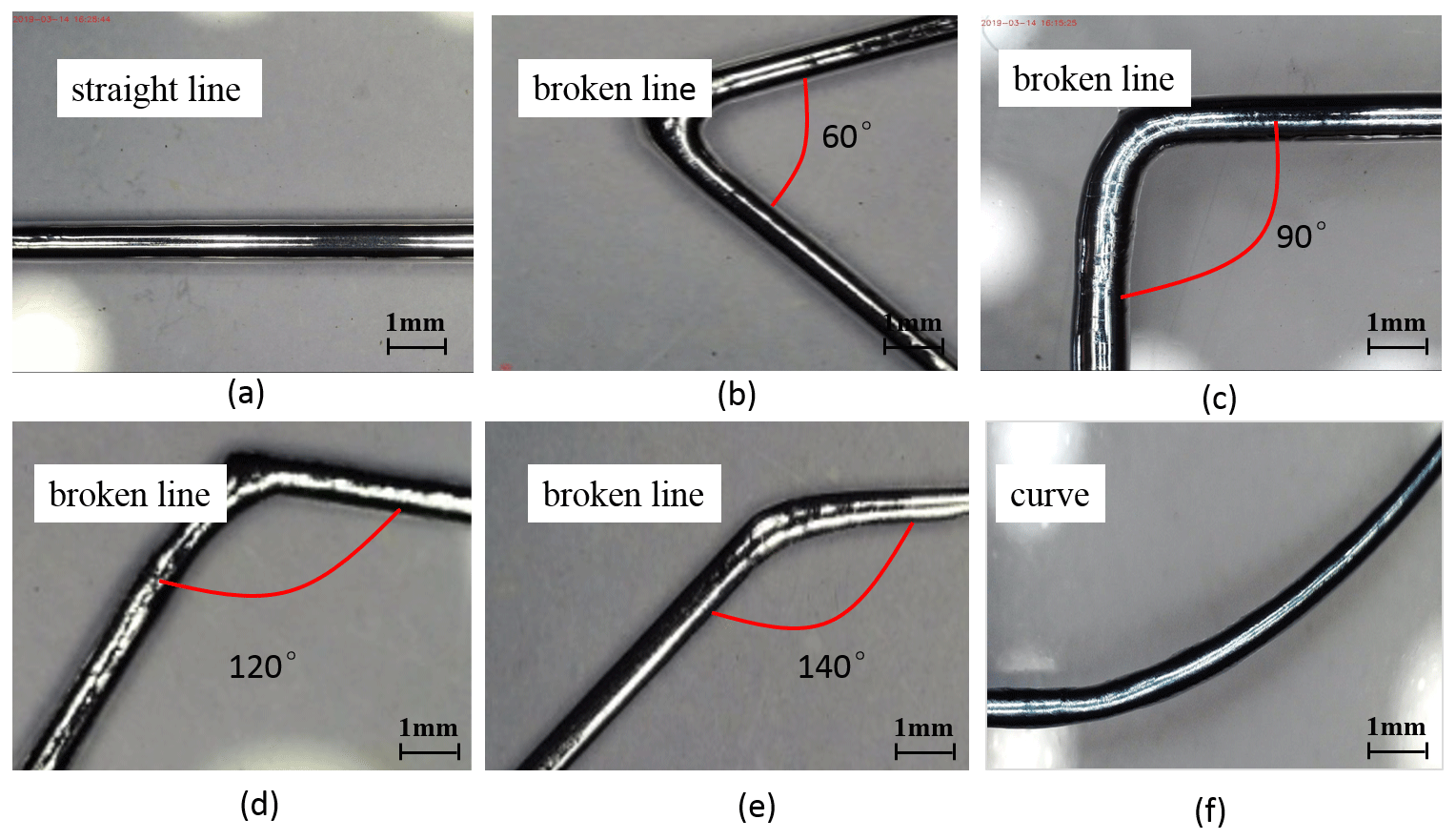
Figure 10Different printed line elements: (a) linear segment; (b–e) corners with different angles; (f) curve.

Figure 11The printed graphic patterns on PVC film substrates: (a) inductance coil; (b) miniature antenna.
Based on the above-described experiments, Fig. 10 shows the elements such as straight lines, angle lines, and curves, which were successfully printed under the writing pressure W=1 N and printing speed VF = F800 mm min−1. The printed lines of the GaIn24.5 alloy exhibited a smooth surface, uniform width, and small size error, under a 40-fold magnification optical microscope. Figure 11 shows an inductance coil and a miniature antenna printed on a PVC film substrate, which have the ability to connect electronic components and conduct electricity.
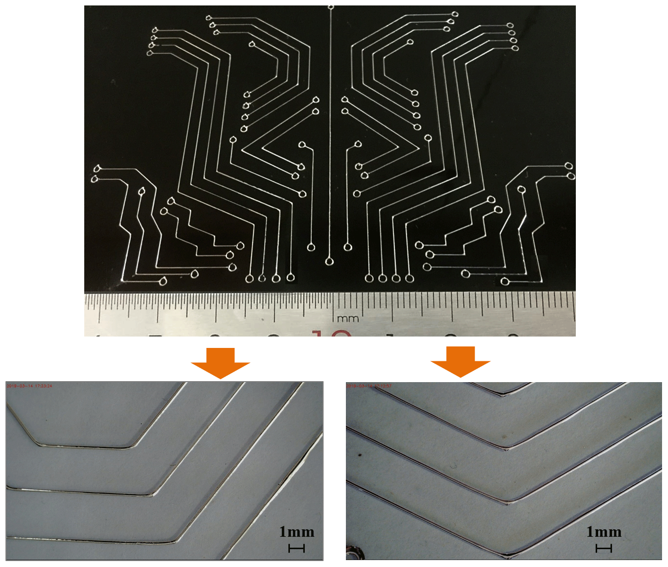
Figure 12 shows the printed flexible PCB on the PVC film substrate, and its wiring and connection can be clearly printed, indicating that use of liquid-metal direct writing is very attractive as a printing technology for future flexible PCB. By changing the printing path code, the wiring direction and the interface location of the electronic components can be adjusted at any time. The printed liquid-metal lines were observed under an optical microscope. Under the 0.5 mm writing diameter of the ball head, the printed line widths were basically distributed between 450 and 500 µm. The edges of the liquid-metal lines were smooth, and the width of the printed lines changed evenly.
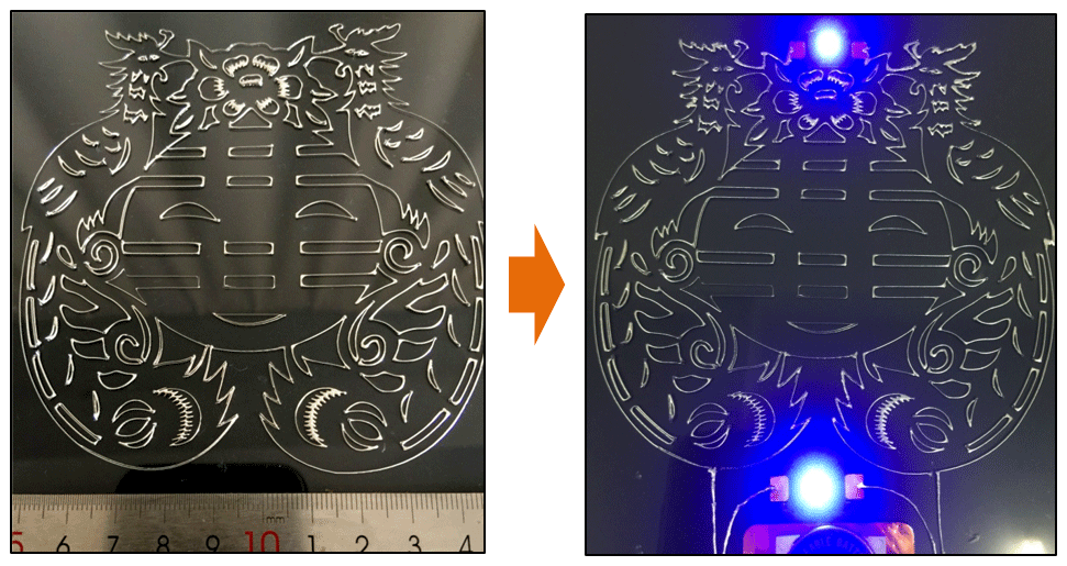
In order to further verify the conductivity of printed liquid-metal wires and the performance of connected electronic components, a functional electronic pattern was successfully printed. Figure 13 illustrates that two light-emitting diodes (LEDs) were embedded in the printed circuit and fixed with silicone encapsulation to ensure contact with the gallium indium alloy circuit. A 3 V button battery was connected to the circuit as a power supply to observe the on–off operation effect of the circuit. After the power supply was connected, two LEDs were successfully lit, proving that the circuit connected by liquid-metal lines is effective and reliable. When the PVC film substrate was properly bent, the circuit could still remain connected, which proves that the circuit is flexible and verifies the correctness and feasibility of the process method proposed in this study.
The conclusions of this paper are as follows:
-
Liquid-metal direct-writing printing technology was proposed to fabricate flexible circuit. The force mechanism of liquid-metal ink transported by ball rotation and translation of the printing head was analysed, and an experimental system was developed. The experimental system mainly included a print head, a 3D motion platform, a pneumatic control unit, a deposition substrate, and a software control system.
-
The wetting characteristics of liquid metal on surfaces of different substrates and its influence on forming morphology were investigated. The wetting effect of the liquid-metal droplets on surfaces of different substrates (PVC plastic film, stainless steel, ABS plastic film, textile cloth, office paper) indicates that the GaIn24.5 droplet shows excellent wetting ability on the thin PVC film.
-
The printing speed and writing pressure are the main factors affecting the forming quality of the printing line. The changing characteristics of shape and size of liquid-metal circuit formed under different writing substrate surface, printing speeds, and writing pressures were experimentally studied. The effective process window for obtaining the best circuit quality was established. For the writing pressures in the range of W = 0.2–1.2 N and the printing speeds of VF = F700–F800 mm min−1, the printed lines have no obvious defects. The surface is smooth, continuous, and changes a little, which is suitable for printing conductive lines.
-
A flexible PCB board circuit and functional electronic pattern were successfully printed under the writing pressure W=1 N and printing speed VF = F800 mm min−1. The printed lines showed a smooth surface, uniform width, small size error, and ability to connect electronic components and conduct electricity. The correctness and feasibility of the liquid-metal direct-writing printing flexible circuit are thus verified.
All data included in this study are available upon request from the corresponding author.
YPC and HY conceived the idea, developed the theory, performed experiments and parameter optimization, and analysed the results. YPC wrote the paper, and HY corrected the paper. HC helped to evaluate the idea and engaged in discussions regarding the outcome. YHL assisted with the editing of the paper.
The authors declare that they have no conflict of interest.
This work was financially supported by the National Natural Science Foundation of China (grant nos. 51305128 and 52005059), the China Postdoctoral Science Foundation (grant no. 2020M673127), the Natural Science Foundation of Chongqing (grant no. cstc2020jcyj-bshX0008), the Fundamental Research Funds for the Central Universities of China (grant no. 2020CDJQY-A035), the “Construction of double city economic circle in Chengdu Chongqing area” scientific and technological innovation project (grant no. KJCXZD2020011), the key scientific and technological project of Henan province (grant no. 192102210055), the key scientific research projects of the colleges and universities of Henan province (grant no. 18A4600050), and Outstanding Young Backbone Teachers projects of Xuchang University.
This paper was edited by Jeong Hoon Ko and reviewed by two anonymous referees.
Chang, H., Guo, R., Sun, Z., Chang, H., Guo, R., Sun, Z. Q., Wang, H. Z., Hou, Y., Wang, Q., Rao, W., and Liu, J.: Direct writing and repairable paper flexible electronics using nickel-liquid metal ink, Adv. Mater. Interfaces, 5, 1800571, https://doi.org/10.1002/admi.201800571, 2018.
Flowers, P. F., Reyes, C., Ye, S., Kim, M. J., and Wiley, B. J.: 3D Printing Electronic Components and Circuits with Conductive Thermoplastic Filament, Addit. Manuf., 18, 156–163, https://doi.org/10.1016/j.addma.2017.10.002, 2017.
Gao, Y. X., Li, H. Y., and Liu, J.: Direct writing of flexible electronics through room temperature Liquid metal ink, PLOS One, 7, 1–10, https://doi.org/10.1007/s00339-013-8191-4, 2012.
Guo, R., Tang, J. B., Don, S. J., Lin, J., Wang, H. Z., Liu, J., and Rao, W.: One-Step Liquid Metal Transfer Printing: Toward Fabrication of Flexible Electronics on Wide Range of Substrates, Adv. Mater. Technol.-US, 3, 1800265, https://doi.org/10.1002/admt.201800265, 2018.
Guo, R., Yao, S. Y., Su, X. Y., and Liu, J.: Semi-liquid metal and adhesion-selection enabled rolling and transfer (SMART) printing: A general method towards fast fabrication of flexible electronics, Sci. China, 62, 982–994, https://doi.org/10.1007/s40843-018-9400-2, 2019.
Haining, Z., Seung, K. M., and Teck, H. N.: 3D Printed Electronics of Non-contact Ink Writing Techniques: Status and Promise, Int. J. Pr. Eng. Man.-G. T., 7, 511–524, https://doi.org/10.1007/s40684-019-00139-9, 2020.
Jeongwoo, L., Ho-Chan, K., Jae-Won, C., and In-Hwan, L.: A Review on 3D Printed Smart Devices for 4D Printing, Int. J. Pr. Eng. Man.-G. T., 4, 373–383, https://doi.org/10.1007/s40684-017-0042-x, 2017.
Kenry, J. C. Y. and Lim, C. T.: Emerging flexible and wearable physical sensing platforms for healthcare and biomedical applications, Microsyst. Nanoeng., 2, 16043, https://doi.org/10.1038/micronano.2016.43, 2016.
Lou, Z., Chen, S., Wang, L., Shi, R. L., Li, L., Jiang, K., Chen, D., and Shen, G. Z.: Ultrasensitive and ultraflexible e-skins with dual functionalities for wearable electronics, Nano. Energy, 38, 28–35, https://doi.org/10.1016/j.nanoen.2017.05.024, 2017.
Mingyu, K., Kang, M., and Kang, K. T.: Flexible 2-Layer Paper Printed Circuit Board Fabricated by Inkjet Printing for 3-D Origami Electronics, Int. J. Pr. Eng. Man.-G. T., 5, 421–426, https://doi.org/10.1007/s40684-018-0045-2, 2018.
Qin, H. T., Cai, Y., Dong, J., and Lee, Y. S.: Direct printing of capacitive touch sensors on flexible substrates by additive E-jet printing with silver nanoinks, J. Manuf. Sci. E.-T. ASME, 139, 031011, https://doi.org/10.1115/1.4034663, 2017a.
Qin, H. T., Dong, J. Y., and Lee, Y. S.: Fabrication and electrical characterization of multi-layer capacitive touch sensors on flexible substrates by additive e-jet printing, J. Manuf. Process., 28, 479–485, https://doi.org/10.1016/j.jmapro.2017.04.015, 2017b.
Sahooa, M., Wang, J. C., Nishina, Y., Liu, Z., Bow, J. S., and Lai, C. S.: Robust sandwiched fluorinated graphene for highly reliable flexible electronics, Appl. Surf. Sci., 499, 1–11, https://doi.org/10.1016/j.apsusc.2019.143839, 2020.
Wang, X., Zhang, Y., and Guo, R.: Conformable liquid metal printed epidermal electronics for smart physiological monitoring and simulation treatment, J. Micromech. Microeng., 28, 034003, https://doi.org/10.1088/1361-6439/aaa80f, 2018.
Wehner, M., Truby, R., Fitzgerald, D., Mosadegh, B., Whitesides, G., Lewis, J., and Wood, R.: An integrated design and fabrication strategy for entirely soft autonomous robots, Nature, 25, 451–455, https://doi.org/10.1038/nature19100, 2016.
Wei, C., Qin, H., Ramírez-Iglesias, N. A., Chiu, C. P., Lee, Y. S., and Dong, J.: High-resolutionac-pulse modulated electrohydrodynamic jet printing on highly insulating substrates, J. Micromech. Microeng., 4, 045010, https://doi.org/10.1088/0960-1317/24/4/045010, 2014.
William, B. J., White, E. L., Chiu, G. C., and Kramer, R. K.: Direct Writing of Gallium-Indium Alloy for Stretchable Electronics, Adv. Funct. Mater., 24, 3474–3474, https://doi.org/10.1002/adfm.201303220, 2014.
Yang, J. and Liu, J.: Direct printing and assembly of FM radio at the user end via liquid metal printer, Circuit World, 40, 134–140, https://doi.org/10.1108/CW-07-2014-0029, 2014.
Zhang, Q., Gao, Y., and Liu, J.: Atomized spraying of liquid metal droplets on desired substrate surfaces as a generalized way for ubiquitous printed electronics, Appl. Phys. A-Mater., 116, 1091–1097, 2014.
Zheng, Y., He, Z. Z., Gao, Y. X., and Liu, J.: Direct Desktop Printed-Circuits-on-Paper Flexible Electronics, Sci. Rep.-UK, 3, 1786, https://doi.org/10.1038/srep01786, 2013.
Zheng, Y. H., Jun, Z. Z., and Liu, J.: Personal electronics printing via tapping mode composite liquid metal ink delivery and adhesion mechanism, Sci. Rep.-UK, 4, 4588, https://doi.org/10.1038/srep04588, 2014.