the Creative Commons Attribution 4.0 License.
the Creative Commons Attribution 4.0 License.
 | 23 Dec 2021
Design and analysis of a six-wheeled companion robot with mechanical obstacle-overcoming adaptivity
Zhen Song
Zirong Luo
Guowu Wei
Jianzhong Shang
A six-wheeled companion exploration robot with an adaptive climbing mechanism is proposed and released for the complicated terrain environment of planetary exploration. Benefiting from its three-rocker-arm structure, the robot can adapt to complex terrain with its six wheels in contact with the ground during locomotion, which improves the stability of the robot. When the robot moves on the flat ground, it moves forward through the rotation of the wheels. When it encounters obstacles in the process of moving forward, the front obstacle-crossing wheels hold the obstacle, and the rocker arms on both sides rotate themselves with mechanical adaptivity to drive the robot to climb and cross the obstacle like crab legs. Furthermore, a parameterized geometric model is established to analyze the motion stability and the obstacle-crossing performance of the robot. To investigate the feasibility and correctness of design theory and robot scheme, a group of design parameters of the robot are determined. A prototype of the robot is developed, and the experiment results show that the robot can maintain stability in rugged terrain environments and has a certain ability to surmount obstacles.
- Article
(20025 KB) - Full-text XML
-
Supplement
(6291 KB) - BibTeX
- EndNote


In the 21st century, planetary exploration has received more and more attention (Ouyang et al., 2003). The United States clearly put forward the plan of returning to the moon in 2019 (He, 2018), and the United States, China, and the United Arab Emirates successively launched Mars probes in July 2020 (Amiri et al., 2021). The cost of sending astronauts to explore planets with harsh surface environments is relatively high, and it is difficult to guarantee the safety of astronauts' lives. Planetary rovers are not only important tools to replace astronauts in the field exploration of planet surfaces, but they are also mobile platforms for scientific instruments (Deng et al., 2008).
Planetary exploration requires the rovers to carry multiple mission equipment and execute different tasks on complicated unknown terrain. Using only one planetary rover to perform all tasks may face a high risk of robot failure and reduce the working efficiency. A group of companion robots can replace the mother planetary rover to perform the exploration task in areas with complex terrain and high exploration value, which will greatly improve the exploration efficiency and reduce the failure risk of the mother planetary rover. Therefore, it is of great value and significance to develop a companion mobile robot, which has good mobility and a certain ability to overcome obstacles and adapt to complicated terrain, to replace the mother planetary rover to perform exploration tasks.
The current mobile robots can roughly be divided into legged, tracked, and wheeled robots (Bruzzone and Quaglia, 2012). As companion robots, legged robots are too complex for the mother planetary rover to control because of their relatively complicated mechanical structures and control systems. Tracked robots always have large weight and high energy consumption, which make them inconvenient for the mother planetary rover to carry, and they cannot perform long-time exploration tasks. By contrast, wheeled robots are best suited as companion robots due to their high energy efficiency and simple control system. But wheeled robots require some structural improvements to enhance their terrain adaptability and capability to climb obstacles.
The six-wheeled planetary exploration robot with rocker-bogie suspension is currently the most widely configured and researched type due to its good obstacle-crossing ability and terrain adaptability. The rocker-bogie suspension was first developed by JPL and was used on Sojourner (Weisbin et al., 1997), MER Mars Exploration Vehicle (Lindemann and Voorhees, 2006), the Perseverance Mars exploration robot (Amiri et al., 2021), Jade Rabbit 2 (Zhang et al., 2021), and Rocky (Volpe et al., 1997) series ground test prototypes. Rocker-bogie suspension has a simple structure, few components, and no elastic elements. It can balance the loads between the six wheels of the robot and has the feature of automatically adapting to topographic fluctuations, especially in soft terrain or terrain with small obstacles. However, suspension structure generally has the disadvantage of coupling and complex structure, and it increases the mass and volume of the robot, which greatly increases the launch cost of the planetary rover.
The four-wheeled planetary exploration robot has good balance stability and mature theory, and its research and application are also common. The four-wheeled planetary robots generally cooperate with deformable chassis to improve the terrain adaptability of the robots and to adjust the size of the robots, for example, the Nomad (Zakrajsek et al., 2005), the Scarab (Wettergreen et al., 2010), the SSR2K (Kozma et al., 2007), the planetary wheel lunar rover developed by Harbin Institute of Technology (Gao, 2005), and the metamorphic center four-wheel lunar rover (Yu, 2009). The four-wheeled robot has a simpler structure and lower quality and energy consumption than a six-wheeled suspension robot; yet its ability to overcome obstacles is too weak to be used as a companion robot.
Five-wheeled robots combine the advantages of the simplicity and lightness of four-wheeled robots and the flexibility of six-wheeled robots in obstacle crossing, for example, Micro5 developed by JAXA (Kubota et al., 2003) and the five-wheel articulated lunar rover developed by Shanghai Jiao Tong University (Liu, 2001a, b). The five-wheel robot has a simpler structure than a suspension robot, which reduces the quality and energy consumption of the mechanical system.
The wheel-legged robot combines the strong terrain adaptability of the leg mobile mechanism with the high-speed and high-efficiency performance of the wheel mobile mechanism and has a strong ability to overcome obstacles. Some wheeled robots are equipped with additional legs connected to the robot body, such as the Wheeleg robot (Lacagnina et al., 2003), the Mantis (Bruzzone and Fanghella, 2014), and the HyTro robot (Lu et al., 2013). According to the terrain conditions, the legs and wheels of these robot can be used alternatively, which makes the design concept of the robot simple. The Sherpa (Cordes et al., 2011), Octopus (Lauria et al., 2002), Chariot (Harrison et al., 2008), ATHLETE (Sunspiral et al., 2012), and the six-wheel-legged lunar robot (Yue et al., 2019; Li et al., 2019) are robots that place wheels on the leg links (usually at the ends of the legs). These robots have multiple joints and wheels to ensure great adaptability to uneven terrain. But the main drawback of these two types of robots is that the degrees of freedom that the robot need to be actuated independently are increased, which makes it complex for the mother planetary rover to dispatch several companion robots.
Locomotion with rotating legs or arms is a suitable solution for small-sized robots to reduce the complexity of the control system while preserving good obstacle-climbing ability, such as the Loper (Herbert et al., 2008), RHex (Altendorfer et al., 2001), and ASGUARD (Waldron et al., 2009). But robots with rotating legs are constantly subjected to shocks and vibrations in the process of movement, which is not conducive to them carrying mission equipment such as cameras.
The EPI.Q robots (Quaglia and Nisi, 2015; Quaglia et al., 2011; Oderio and Quaglia, 2009) and a passive underactuation technique suggested by Carl A. Nelson (Nelson, 2012) proposed a planetary gear train for obstacle overcoming in wheeled robots. Using planetary gear trains with 1 input degree of freedom and 2 output degrees of freedom, the robots can switch from a wheel locomotion to a leg locomotion depending on the dynamic conditions. The legs can rotate independently to climb obstacles, while on flat ground only the wheels are active, which simplifies the control and sensing system of the robots.
Inspired by the above research, especially the six-wheeled rocker-bogie-type rovers and the robots with rotating legs, and combined with China's future exploration requirements, a small three-rocker-arm six-wheeled robot with adaptive obstacle-crossing capability, independent of complex perception and control, was proposed to perform exploration tasks instead of the mother planetary rover. Compared to other mobile robots, it has the advantages of high working efficiency, stable motion, and simple control system. Relying on its three-rocker-arm structure, the robot has strong adaptability to complex terrain and can climb over irregular obstacles by flipping the adaptive climbing rocker arms, which has broad application prospects in short-term small-range planetary exploration.
The rest of the paper is arranged as follows. Section 2 introduces the composition and structure of the proposed mobile robot. Then, Sect. 3 performed the analysis of the robot's terrain adaptability and obstacle-crossing ability. And in Sect. 4, a prototype of the proposed robot is developed and presented, leading to field tests verifying the feasibility, maneuverability, and obstacle-crossing performance of the proposed mobile robot.
2.1 Design requirement of the micro companion robot
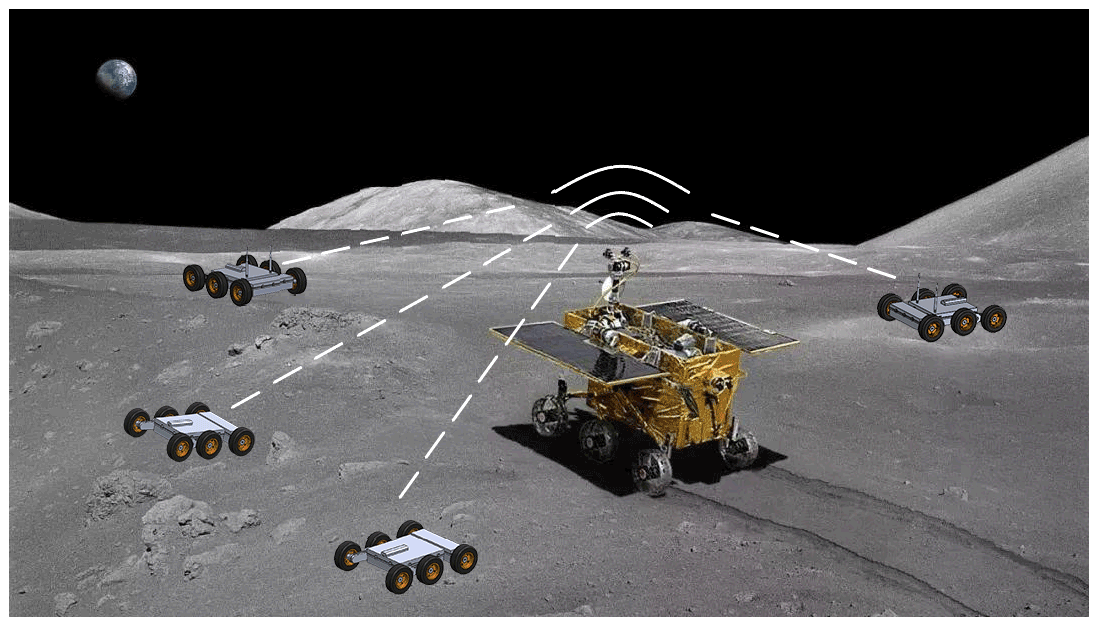
The purpose of this study is to develop a small self-adaptive obstacle-crossing robot that accompanies the large-scale planetary rover to perform various exploration tasks, as illustrated in Fig. 1. The potential role of the micro robot includes road pioneer, map builder, and swarm collaborative robots for complicated missions. Different from large exploration vehicles for carrying all the facilities to perform all kinds of challenging tasks, a companion robot is more compact and lighter. Our goal is to design a portable mini companion robot, whose size is about 600 mm × 450 mm × 150 mm, with a simple mechanical structure and control system for securing reliability. This robot has the following characteristics:
-
Light weight. The total weight of the robot is less than 10 kg, with some extra weight from typical associated exploration devices, such as cameras, microphones, wireless communication devices, and additional task-oriented sensors.
-
High maneuverability. The robot can move in the unstructured environment of the planet surface and can climb vertical obstacles of 80 mm height; the robot can pivot around a vertical axis on flat grounds to avoid complex maneuvers with backward motion in narrow spaces.
-
Stable motion. The robot has the ability of vibration-free movement in the unstructured environment characterized by uneven terrain and irregular obstacles and can maintain the stability of the camera and the exploration devices.
-
Network communication capabilities. The robot can form a robot community with the parent vehicle and other child vehicles to perform exploration tasks in coordination.
-
Automatic return for energy recharge. After the robot goes out to perform tasks, it can build a map and return to the parent vehicle to charge and replenish energy.
2.2 Mechanical structure of the self-adaptive obstacle-crossing six-wheeled robot
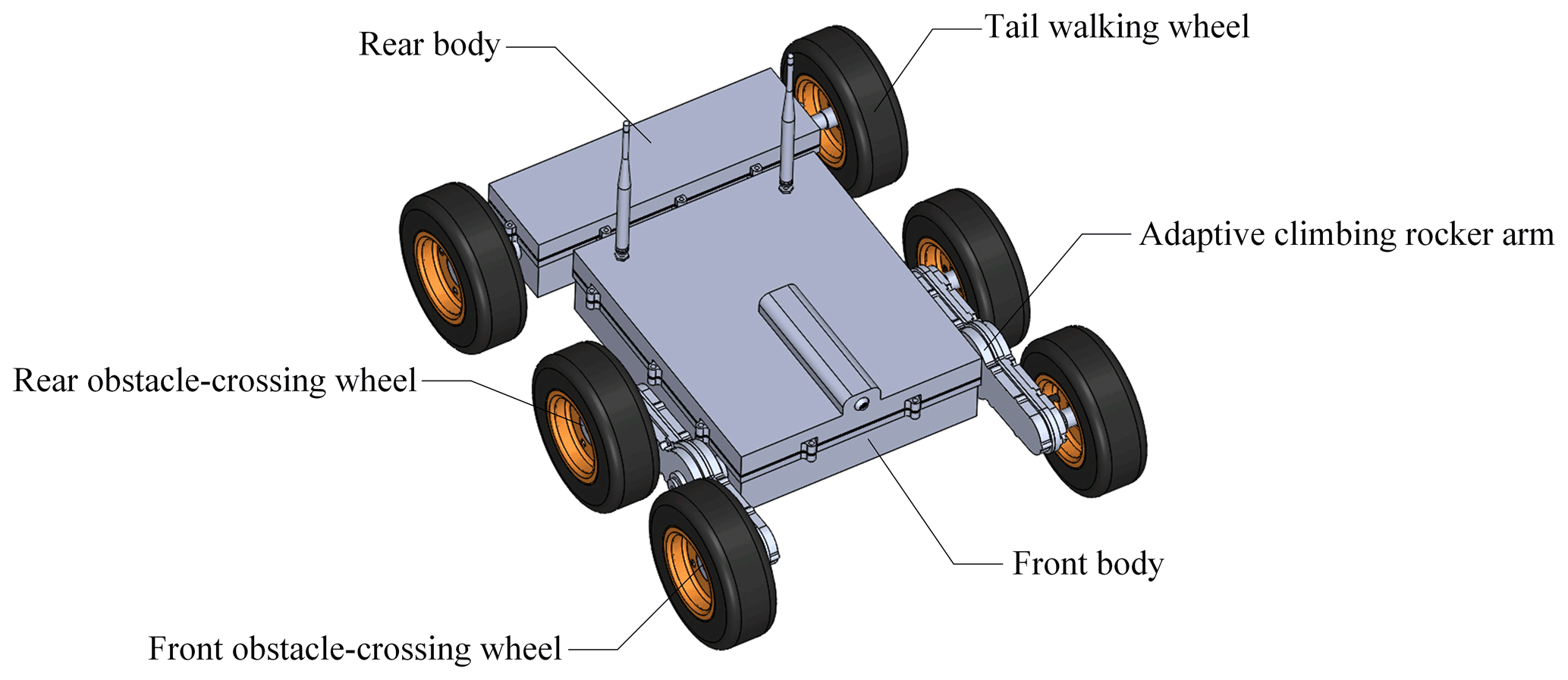
According to the above design requirements, a self-adaptive obstacle-crossing six-wheeled robot is designed. As shown in Fig. 2, the robot consists of a two-wheeled rear body and a four-wheeled front body with two adaptive climbing rocker arms. The front body and the rear body are used as carriers to accommodate modules such as motors, batteries, and control plate. To improve the self-adaption of six wheels to terrain, the rear body is connected to the front body with a rotation axis; thus the rear body can act as a rocker arm relative to the front body. Two sets of adaptive climbing rocker arms for obstacle crossing are symmetrically mounted to the front body, and on each of them there are two obstacle-crossing wheels. The rear body and the two adaptive climbing rocker arms on both sides compose the three rocker arms of the robot. They can rotate freely and passively relative to the front body so as to keep the wheels of the robot in contact with the ground, which enhances the terrain adaptability of the robot.
Unlike classic rocker bogie structures, which are mainly used to improve the terrain adaptability of the robot, the adaptive climbing rocker arms of the proposed robot can also enhance the obstacle-crossing ability of the robot by turning. As illustrated in Fig. 3a, the adaptive climbing rocker arm is comprised of a parallel-axis gear train and a planetary epicyclic gear train. The parallel-axis gear train contains a motor gear, a primary gear, and a secondary gear and is driven by a DC motor. Because a large torque is in need for the adaptive climbing rocker arm to overturn and cross obstacles, the primary gear and secondary gear in the parallel-axis gear train are used to increase the torque output of the motor. The planetary epicyclic gear train are accommodated in the adaptive climbing rocker arm, which is regarded as the planetary gear frame, and two obstacle-crossing wheels are fixed on the wheel shafts on both ends of the rocker arm. Figure 3b shows the schematic diagram of the gear transmission in the adaptive climbing rocker arm. It can be seen that the secondary gear (gear 3 in Fig. 3b) of the parallel-axis gear train and the sun gear (gear 3′ in Fig. 3b) of the epicyclic gear train rotate synchronously and share the same shaft. The rocker planetary epicyclic gear train is used to increase the speed of the obstacle-crossing wheels when the robot moves on the flat ground and is composed of a sun gear, a planetary frame, and four planetary gears and a wheel shaft on each side. And the transmission ratio between the wheel shaft and the sun gear, denoted as i73, is set to 3.8.
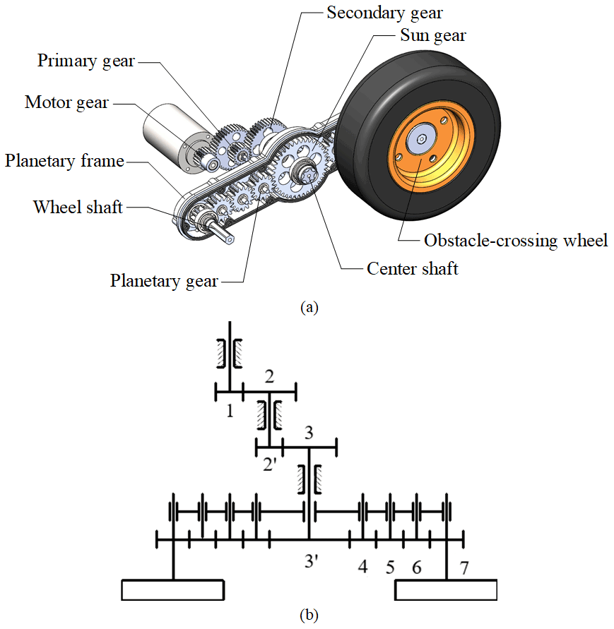
Figure 3Structure and transmission of the adaptive climbing rocker arm. (a) The composition of the adaptive climbing rocker arm and (b) the gear transmission diagram in the adaptive climbing rocker arm.
2.3 Principle of adaptive motion and obstacle crossing of the six-wheeled robot
The rocker arms on both sides of the robot and the rear body can rotate freely relative to the front body, which together constitute the three-rocker-arm structure of the robot. As shown in Fig. 4, relying on its three-rocker-arm structure, the robot can adapt to different terrain and maintain all the wheels in contact with the ground, so as to improve the stability and obstacle-crossing capability of the robot.
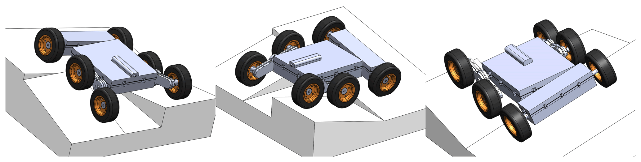
Figure 4The robot can adapt to different terrain and maintain all the wheels in contact with the ground, relying on its three-rocker-arm structure.
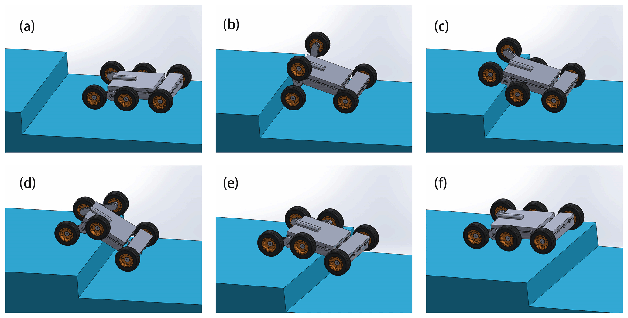
Thanks to the adaptive climbing rocker arms, the robot can climb over the obstacle like crab legs, as shown in Fig. 5. It generally takes six steps. When the robot moves on the flat ground, the adaptive climbing rocker arms do not turn over (see Fig. 5a). After the front obstacle-crossing wheels encounter the obstacle and are blocked by the friction with the obstacle vertical surface, a large torque will exert on the climbing rocker arms by the sun gear, which will rotate the climbing rocker arms and push the robot to climb the obstacles like crab legs (see Fig. 5b). When the rear obstacle-crossing wheels hit the edge of the obstacle (see Fig. 5c), the adaptive climbing rocker arms continue to turn over and lift the body, with the tail walking wheels pushing the robot forward (see Fig. 5d). Subsequently, when the body of the robot contacts the edge of the obstacle, the obstacle-crossing wheels roll forward, raising the tail walking wheels (see Fig. 5e) and pulling the whole robot until it climbs over the obstacle (see Fig. 5f).
3.1 Parameterized design model of the self-adaptive obstacle-crossing six-wheeled robot
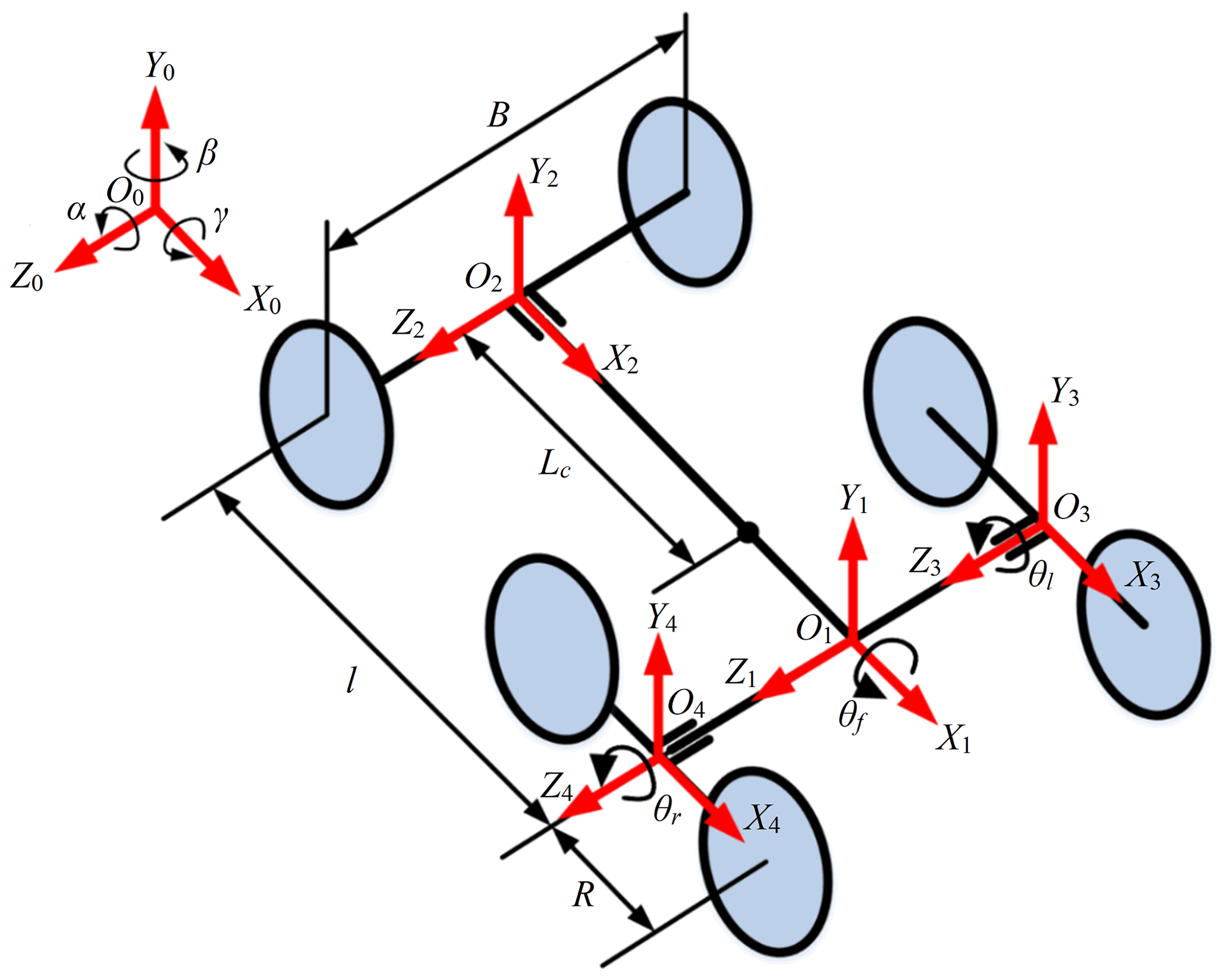
To better analyze the terrain adaptability and obstacle-crossing performance of the robot, the geometric parameter model of the robot is established. The main geometrical parameters of the robot are shown in Fig. 6. In the model, the coordinate frame is the fixed inertia frame, is the robot's front body coordinate frame, is the robot's rear body coordinate frame, is the left adaptive climbing rocker arm coordinate frame, and is the right adaptive climbing rocker arm coordinate frame. O1 is the intersection of the centerline of the robot's front body and the rotation axes of the adaptive climbing rocker arms on both sides. O2 is the intersection of the centerline of the robot's body and the rotation axes of the tail walking wheels on both sides. O3 is the center of the left adaptive climbing rocker arm, and O4 is the center of the right adaptive climbing rocker arm. In addition, the structure and geometric parameters of the robot are defined as shown in the figure, where B is the width of the robot, l is the common length of the front and rear bodies, R is the radius of the adaptive climbing rocker arm, r is the radius of the wheels (all the wheels are of the same dimension), 2d1 is the thickness of the robot body, and Lc is the distance between the common centroid of the robot's front and rear body and the origin O2 of the coordinate frame . θl and θr are respectively the swing angles of the left and right adaptive climbing rocker arms, and θf is the rotation angle of the rear body with respect to the coordinate frame in the X2–Y2 plane. The structure parameters are collected in a vector as [l R r d1 B]T, and the geometric variables are expressed in a vector as [θf θr θl]T.
3.2 Kinematical model of the centroid for robot obstacle overcoming
The change of the centroid position will affect the smoothness and stability of the robot in motion and also directly affect the energy consumption of the robot. The robot proposed in this paper adopts a unique three-rocker-arm structure. In the process of robot motion, the adaptive rotation of the rocker arm to the ground can not only equalize the contact force between the ground and the wheels, but also reduce the influence of single wheel fluctuation on the position of the centroid
In this section, the centroid kinematics model of the robot is established to analyze the robot's adaptive motion and obstacle-crossing process. Referring to Fig. 6, the rotation matrix of the robot's front body coordinate frame relative to the fixed coordinate frame is (Liu, 2018)
In Eq. (1), α, β, and γ are, respectively, the pitch angle, steering angle, and roll angle of the robot. In this equation, c stands for the cosine function, and s stands for the sine function; the same notation is used for the rest of the equations. Let the coordinate of O1 in the fixed coordinate frame be (a, b, c). The transformation matrix of the robot coordinate frame relative to the fixed coordinate frame can be obtained in the homogeneous transformation matrix form as
Further, the transformation matrix of the rear body and the two adaptive climbing rocker arms with respect to the robot coordinate frame can be written as
for the rear body,
for the left adaptive climbing rocker arm, and
for the right adaptive climbing rocker arm.
For the convenience of analysis, assuming the centroid of each part of the robot is in its geometric center, the expression of the centroid of the whole robot in the robot coordinate frame is as follows:
In Eq. (6), m1, m2, and m3 represent the total mass of the robot's front and rear body, the mass of the adaptive climbing rocker arm, and the mass of the wheel, respectively. m represents the mass of the whole robot, and . 1p1, 1pr, 1pl, 1plw, and 1prw are, respectively, the coordinate vectors of the common centroid of the robot's front body and rear body, the centroids of the adaptive climbing rocker arms, and the centroids of the tail walking wheels in the robot coordinate frame . 1plf, 1plr, 1prf, and 1prr are the vectors of centroids of the obstacle-crossing wheels. And referring to Fig. 6, there are
By substituting Eqs. (7) to (11) into Eq. (6), the vector of the centroid of the whole robot with respect to the robot coordinate frame can be obtained as
Hence, the robot's center of mass coordinate in the fixed coordinate frame is
In the same way, the coordinates y of other parts of the robot in fixed coordinate frame can be obtained as follows:
In the process of movement, the change of steering angle has little effect on the position of the robot's centroid in the vertical direction. By ignoring the steering angle β and solving Eqs. (17) and (18), the relationship between the pitch angle α, roll angle γ, the position change of the robot's centroid in the coordinate frame , and the six wheels' positions in the process of movement can be obtained:
3.3 Analysis of robot locomotion stability
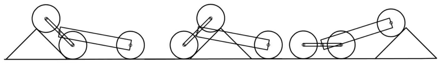
Depending on its three-rocker-arm structure, the robot can adapt itself to irregular terrain, keep its motion smooth, and reduce the fluctuation of the robot's centroid. When a single wheel crosses the obstacle, the other wheels can remain in contact with the ground. In this section, to analyze the influence of the three-rocker-arm structure on the terrain adaptability of the robot, changes in the pitch angle, roll angle, and centroid height of the robot are calculated when each wheel passes over a right triangle obstacle in turn unilaterally or bilaterally, as shown in Fig. 7.
In the proposed design, the geometric design parameters of the robot are l=400 mm, B=355 mm, R=105 mm, r=77.5 mm, m1=6.4 kg, m2=1.6 kg, m3=0.55 kg, and . Substituting these parameters into Eqs. (19), (20), and (21), the curve of the robot's pitch angle α, roll angle γ, and centroid height 0y0 changing with time is shown in Fig. 8, in which case the robot crosses the obstacle unilaterally or bilaterally, and it is assumed that each wheel of the robot rotates at a constant speed 10 mm/s, and the maximum height of the obstacle is 97 mm. It can be seen from Fig. 8 that although the height of the obstacle is 97 mm, the maximum increase in robot's centroid is only 56 mm when the robot crosses the obstacle on both sides and 28 mm when the robot crosses the obstacle on one side. So, whether the robot crosses obstacles unilaterally or bilaterally, the three-rocker-arm structure can effectively reduce the fluctuation of the height of the robot's centroid. And due to the three-rocker-arm structure, the maximum pitch angle when the robot crosses obstacles unilaterally is only 5.7∘, which is almost only half of that (11.57∘) when the robot crosses obstacles bilaterally.
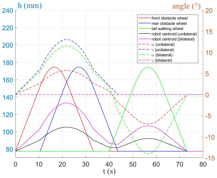
Figure 8The curve of pitch angle α, roll angle γ, and centroid height 0y0 changing with time when the robot crosses the obstacle unilaterally or bilaterally.
Further, assuming the initial coordinate b of robot coordinate frame relative to the fixed coordinate system is b0=r, the curves of the height of the robot's centroid relative to initial position 0y0−b0 changing with the height of the obstacle are shown in Fig. 9a, and the curves of the robot's pitch angle α and roll angle γ are shown in Fig. 9b, for the case that the robot's three wheels on one side pass over the obstacle's highest point in turn. It can be seen from the figures that when the robot is crossing the obstacle, the influences of the front and rear obstacle-crossing wheel on the height of the robot's centroid are equivalent. When the front and rear obstacle-crossing wheels cross the obstacle, the centroid of the robot only rises by 0.175 mm when the obstacle rises by 1 mm; when the tail walking wheel surmounts the obstacle, the centroid only rises by 0.15 mm when the obstacle rises by 1 mm. The influences of the front and rear obstacle-crossing wheels on the pitch angle and roll angle of the robot are equivalent, and the tail walking wheel has no effect on the roll angle of the robot.
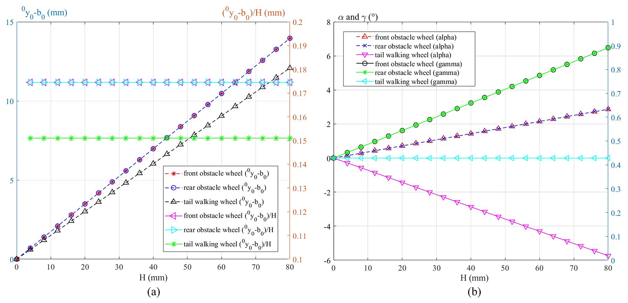
Figure 9(a) The curves of the height of the robot's centroid relative to initial position 0y0−b0 changing with the height of the obstacle and (b) the curves of the robot's pitch angle α and roll angle γ changing with the height of the obstacle.
According to the above results, we can see that the three-rocker-arm structure can indeed reduce the fluctuation of the robot's center of mass and pitch angle in the process of motion, which improves the terrain adaptability and motion stability of the robot.
3.4 Kinematic analysis of robot obstacle crossing
To analyze the influence of the three-rocker-arm structure on the obstacle-crossing stability of the robot, changes in the pitch angle and roll angle of the robot are calculated in this section when the robot climbs over the obstacle unilaterally and bilaterally. Figure 10 shows an obstacle-crossing configuration of the robot; after bumping into the obstacle, the robot turns over the left adaptive climbing rocker arm and raises the left rear obstacle-crossing wheel, while the other five wheels keep in contact with the ground. In this configuration, it has
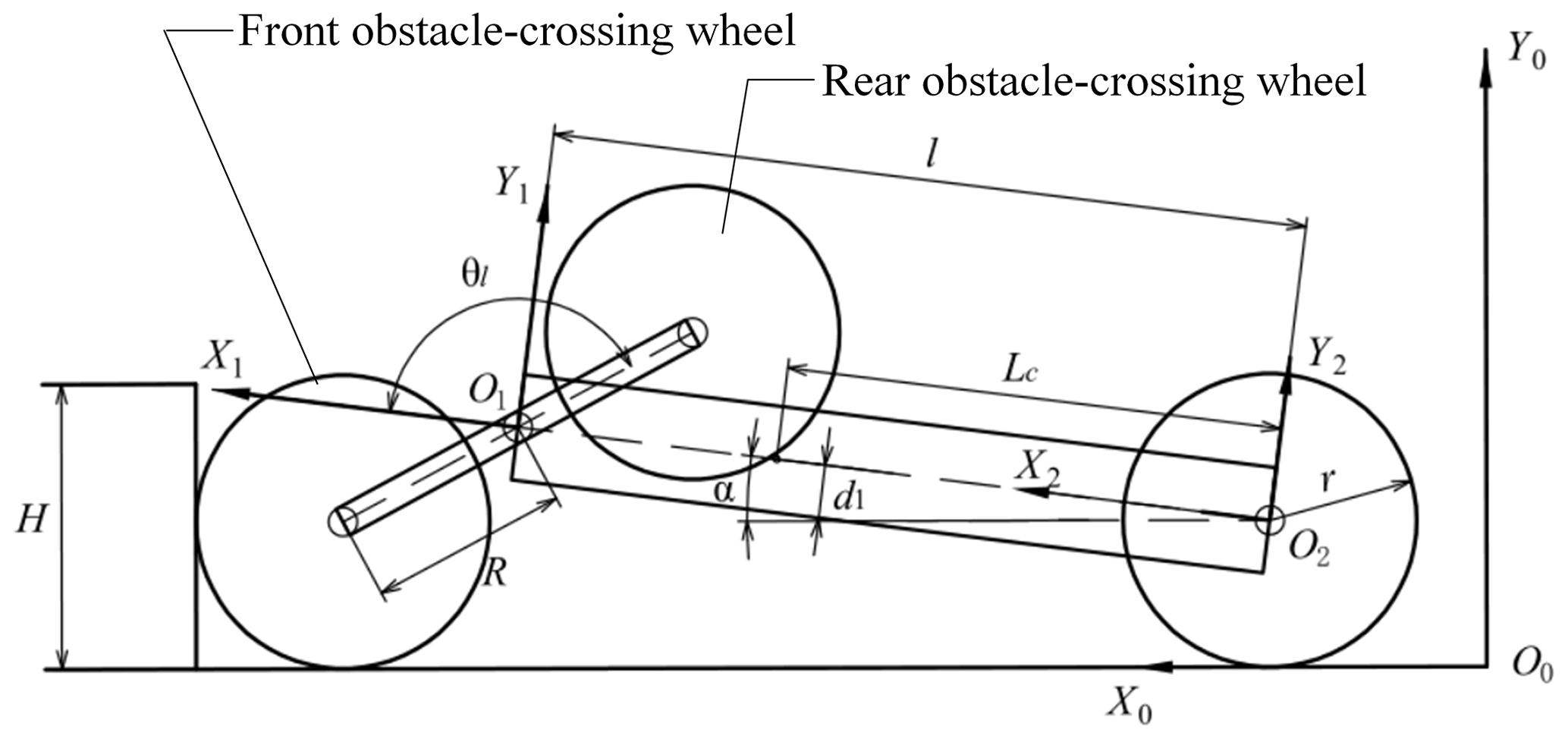
Figure 10The robot turns over the left adaptive climbing rocker arm after resisting the obstacle.
Substituting Eq. (24) into Eqs. (19), (20), and (22) yields
As shown in Fig. 11, after the left rear obstacle-crossing wheel is on the surface of the obstacle (see Fig. 11a), the adaptive climbing rocker arm will continue to turn and lift the front obstacle-crossing wheel (see Fig. 11b).
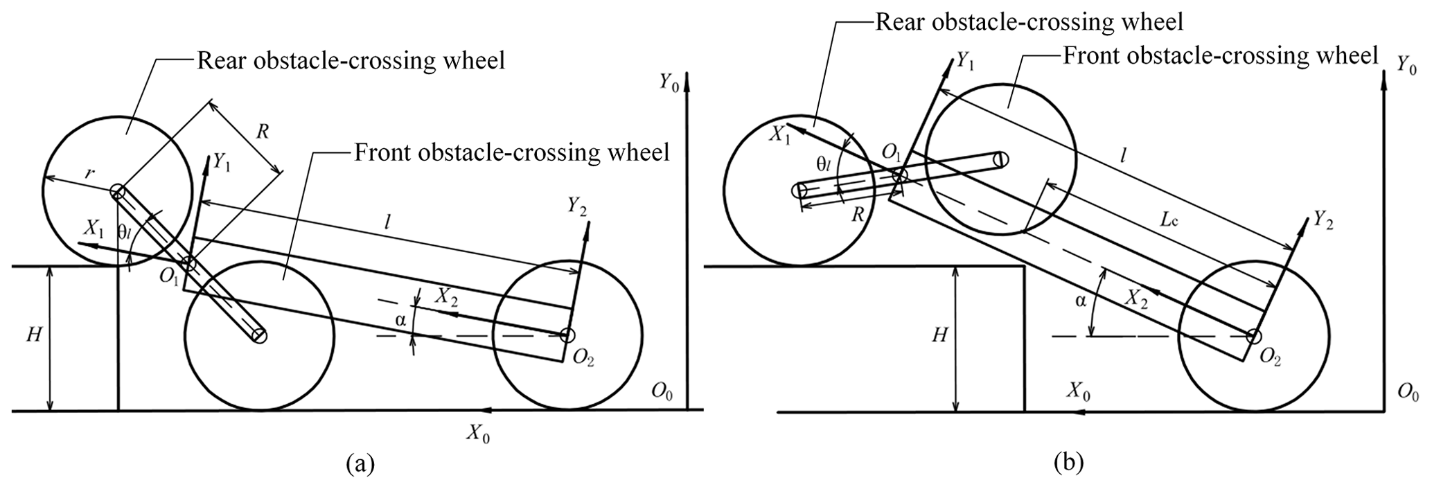
Figure 11The adaptive climbing rocker arm continues to turn and lift the front obstacle-crossing wheel.
In Fig. 11b, the geometrical relationship between the robot and the obstacle satisfies the following equations:
Substituting Eq. (26) into Eqs. (19), (20), and (22) leads to
The height of the obstacle is assumed to be 80 mm. Substituting the robot's geometrical parameters into Eqs. (25) and (27) and solving them by using MATLAB, the curve of the pitch angle α and the roll angle γ changing with the swing angle θl of the left adaptive climbing rocker arm can be obtained. In the same way, we can get the curve of the robot's pitch angle and roll angle changing with the swing angle of the adaptive climbing rocker arms when the robot climbs the obstacle bilaterally. Figure 12 shows the curves of the pitch angle α and the roll angle γ changing with the swing angle of the adaptive climbing rocker arm.
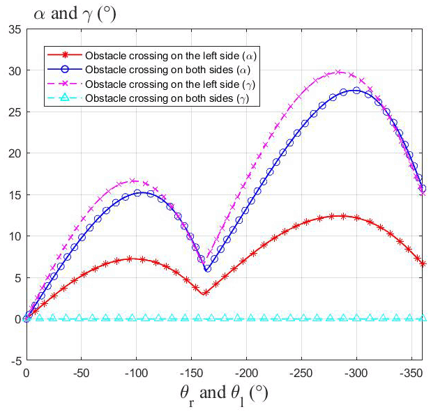
Figure 12The curves of the pitch angle α and the roll angle γ changing with the swing angle of the adaptive climbing rocker arm.
It can be seen from Fig. 12 that when the robot crosses the obstacle unilaterally, its pitch angle and roll angle first increase and then decrease after contacting the obstacle. When the rear obstacle-crossing wheel of the robot reaches the edge of the obstacle, the adaptive climbing rocker arm continues to overturn and prop up the robot, so that the pitch angle and roll angle of the robot continue to increase. The maximum pitch angle is 12.4∘, and the maximum roll angle is 30∘. When the robot crosses the obstacle bilaterally, the pitch angle changes approximately twice as much as that on one side, and the maximum value is 27.5∘, while the roll angle remains at 0. It can be seen that the three-rocker-arm structure of the robot can slow down the changes of the robot's pitch angle when the robot crosses the obstacle unilaterally and keep the robot moving smoothly.
3.5 Static analysis of robot obstacle crossing
The following two conditions must be satisfied for the robot to climb obstacles successfully:
-
When the robot contacts the obstacle, the adaptive climbing rocker arm can flip and lift the robot's body.
-
When the body of the robot contacts the edge of the obstacle, the adaptive climbing rocker arms can continue to turn over and pull the robot to climb over the obstacle.
To analyze condition (1), the static condition of the robot in the obstacle-crossing phase (b) is shown in Fig. 13.
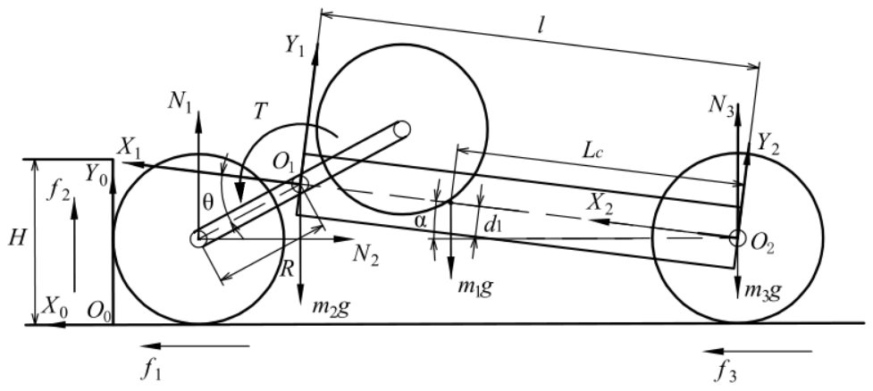
Based on the analysis of the static condition of the robot in the obstacle-crossing phase (b), the following formulas are deduced:
Among them, N2 represents the supporting force of the obstacle on the front walking wheel, N1 and N3 represent the supporting force of the ground against the front obstacle-crossing wheel and the tail walking wheel respectively, f2 represents the friction force of the obstacle on the front walking wheel, f1 and f3 represent the friction force of the ground against the front obstacle-crossing wheel and the tail walking wheel respectively, and T is the torque of the center gear shaft of the adaptive climbing rocker arm. And the same notation is used in the rest of the equations.
The first and second lines of Eq. (28) represent the static conditions of the robot in the horizontal and vertical directions respectively. The third and fourth lines represent the torque of the adaptive climbing rocker arm's central gear shaft acting on the robot's body and the adaptive climbing rocker arm respectively. The same implications are also used in Eq. (38). According to Fig. 3b, the relationship between the friction torque of the obstacle-crossing wheel and the torque of the central gear shaft of the adaptive climbing rocker arm is
And for the case shown in Fig. 13, the geometrical relationship between the robot and the obstacle satisfies the following equation:
It is assumed that the sliding friction coefficient between the wheel and the ground is μ. If the tail walking wheels can also lift the robot's body under the condition of sliding friction, the body can also be lifted when the pressure on the tail walking wheel is large enough. Therefore, it is assumed that the robot's tail walking wheels are rotating relative to the ground, and the friction force on the walking wheel is f3=μN3.
By solving Eqs. (28) to (30), the torque of the adaptive climbing rocker arm's central gear shaft can be obtained as
where
and
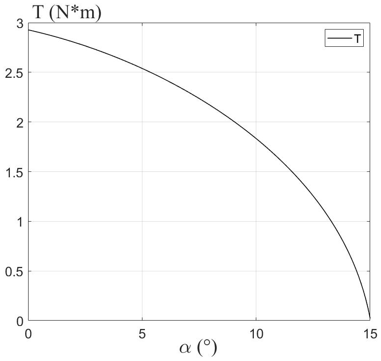
Figure 14 shows the variation of T with the pitch angle α, where the coefficient of friction μ=0.3. It can be seen from the result that with the increase of the pitch angle, T gradually decreases, and the curve represents the minimum output torque of the central gear shaft during the adaptive climbing rocker arm rotation process. As long as the output torque T of the central gear shaft is greater than the curve, the robot satisfies the condition (1).
Condition (2) should be analyzed from two aspects: geometrics and statics. When the robot's main body collides with the edge of the obstacle, the robot will continue to turn over the adaptive climbing rocker arms to prop up the body because the movement is hindered. In geometrics, only if the centroid of the robot is higher than the upper surface of the obstacle and within the edge of the obstacle can the robot climb up the obstacle, relying on the traction of the obstacle-crossing wheels. In statics, the torque output by the adaptive climbing rocker arm must be large enough to prop up the robot, and the friction between the obstacle-crossing wheels and the upper surface of the obstacle is enough to pull the robot to climb over the obstacle after the tail walking wheels are off the ground.
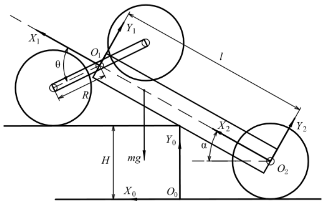
To analyze the geometric condition, the geometric configuration of the robot at the critical state of the robot obstacle-crossing phase (d) is shown in Fig. 15. And the geometric condition can be summarized as follows:
The first line of Eq. (35) represents that the centroid of the robot is higher than the upper surface of the obstacle. The second line represents that the centroid is within the edge of the obstacle. The third line represents that the obstacle-crossing wheels can touch the upper surface of the obstacle. It can be seen that when the robot's configuration satisfies the condition in the first line, it must also satisfy the condition in the second line. So, Eq. (35) can lead to two further functions with respect to α:
where G1(α)>H and G2(α)<H are the geometric conditions of condition (2).
To analyze the static condition, the static condition of the robot at the critical state of the robot obstacle-crossing phase (d) is shown in Fig. 16. In this case, the centroid of the robot has crossed the edge of the obstacle, and the tail walking wheels of the robot are about to leave the ground.

Based on the analysis of the static condition of the robot in the obstacle-crossing phase (b), the following formulas are deduced:
In Eq. (38), N5 represents the support force of the obstacle to the robot body, and f5 represents the friction force of the edge of the obstacle to the robot body. k represents the distance from the contact point between the body of the robot and the edge of the obstacle to the front of the body; that is
Referring to Fig. 16, the geometrical relationship between the robot and the obstacle satisfies the following equation:
According to Fig. 3b, the relationship between the friction torque of the front obstacle-crossing wheel and the output torque of the central gear shaft of the adaptive climbing rocker arm can be obtained as
Ignoring the friction between the body of the robot and the obstacle can simplify the analysis; i.e. f5=0. The torque output by the central gear shaft of the adaptive climbing rocker arms must be large enough to prop up the robot, and the friction between the obstacle-crossing wheels and the upper surface of the obstacle is enough to pull the robot to climb over the obstacle after the tail walking wheels are off the ground. So, it is assumed that the obstacle-crossing wheels roll purely on the surface of the obstacle, and N3=0 and f3=0 at this time.
Solving Eqs. (38) to (41), the relationship between the height H of the obstacle and the pitch angle α of the robot when it is at the critical state of the obstacle-crossing phase (d) can be expressed as the following equation:
Only when the tail walking wheels are about to be released from the ground and the pitch angle α and the height H of the obstacle satisfy Eq. (42) can it be considered that the robot can climb over the obstacle with height H. Otherwise, the tail walking wheels of the robot cannot leave the ground.
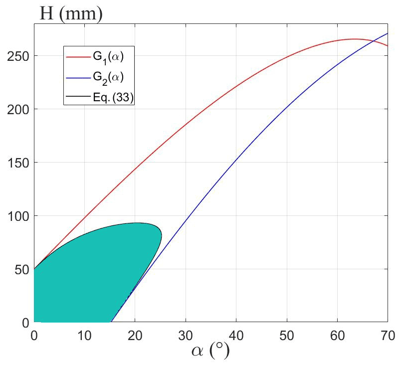
The substitution of the geometric and mass parameters of the robot into Eqs. (36), (37), and (42) and the curves of G1(α), G2(α), and Eq. (42) changing with α are shown in Fig. 17. In Fig. 17, between the red line and the blue line is the area where the robot satisfies the geometric obstacle-crossing conditions. The black line represents the critical state where the robot satisfies Eq. (42). The shaded part represents the feasible region for the robot to cross obstacles at different pitch angles. It can be seen from the figure that when the pitch angle is α=21∘, the maximum obstacle-crossing height of the robot is 93 mm. Moreover, as long as the robot satisfies Eq. (42) in the critical state, it must satisfy the geometric conditions at the same time. And the maximum obstacle height satisfying Eq. (42) is the maximum obstacle-crossing height of the robot.
In addition, to analyze the influence of other geometric parameters on the maximum obstacle-crossing height of the robot, keep the quality of the robot unchanged, take R as 90, 105, and 120 mm respectively, and make the curves of Eq. (42), as shown in Fig. 18a. Similarly, take l as 350, 400, and 450 mm, and take r as 72.5, 77.5, and 82.5 mm respectively, and make the curves of Eq. (42), as shown in Fig. 18b and c. It can be seen from the figure that increasing R, l, and r can increase the maximum obstacle-crossing height of the robot.
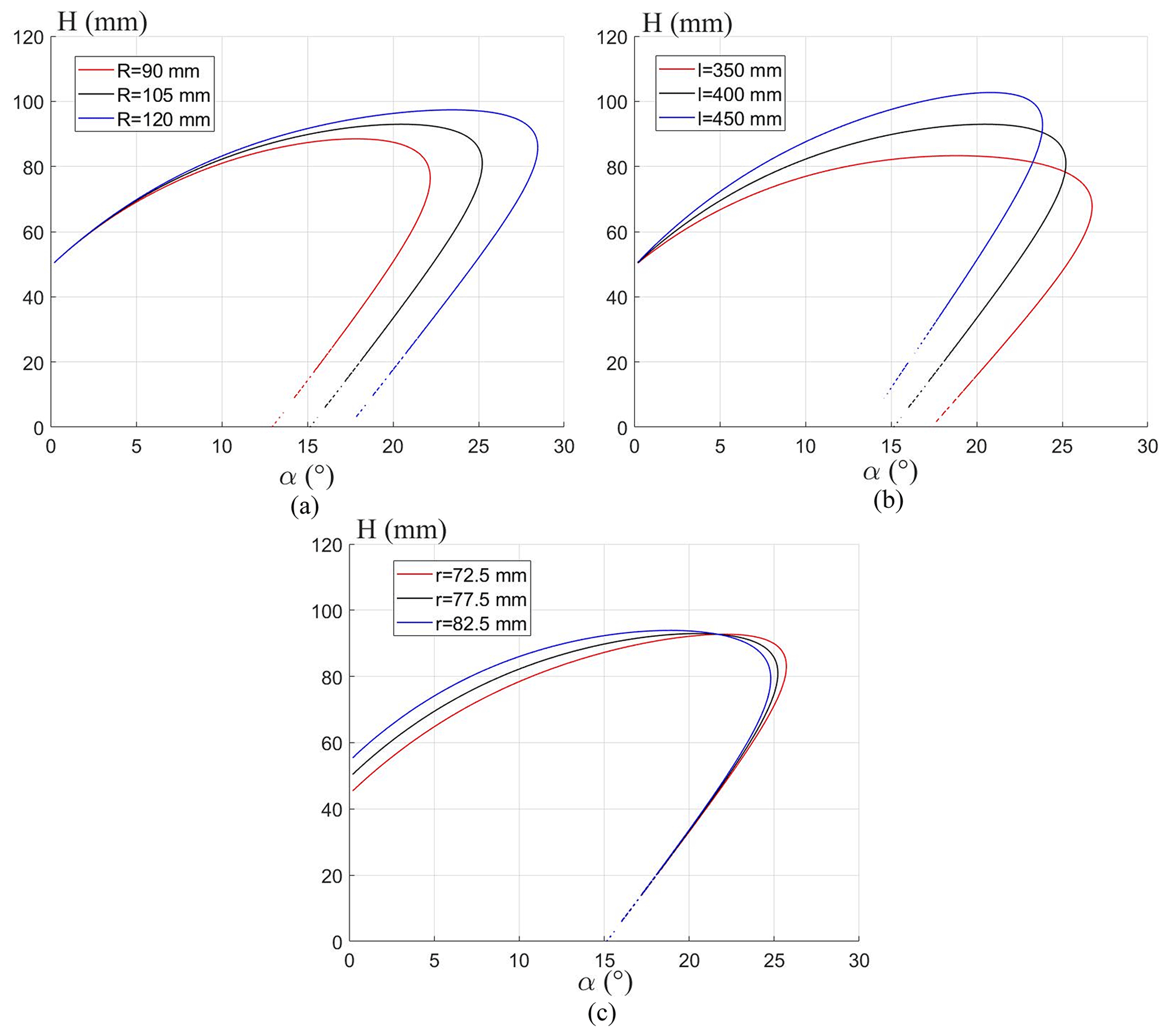
Figure 18The influence of other geometric parameters on the maximum obstacle-crossing height of the robot.
4.1 Prototype development
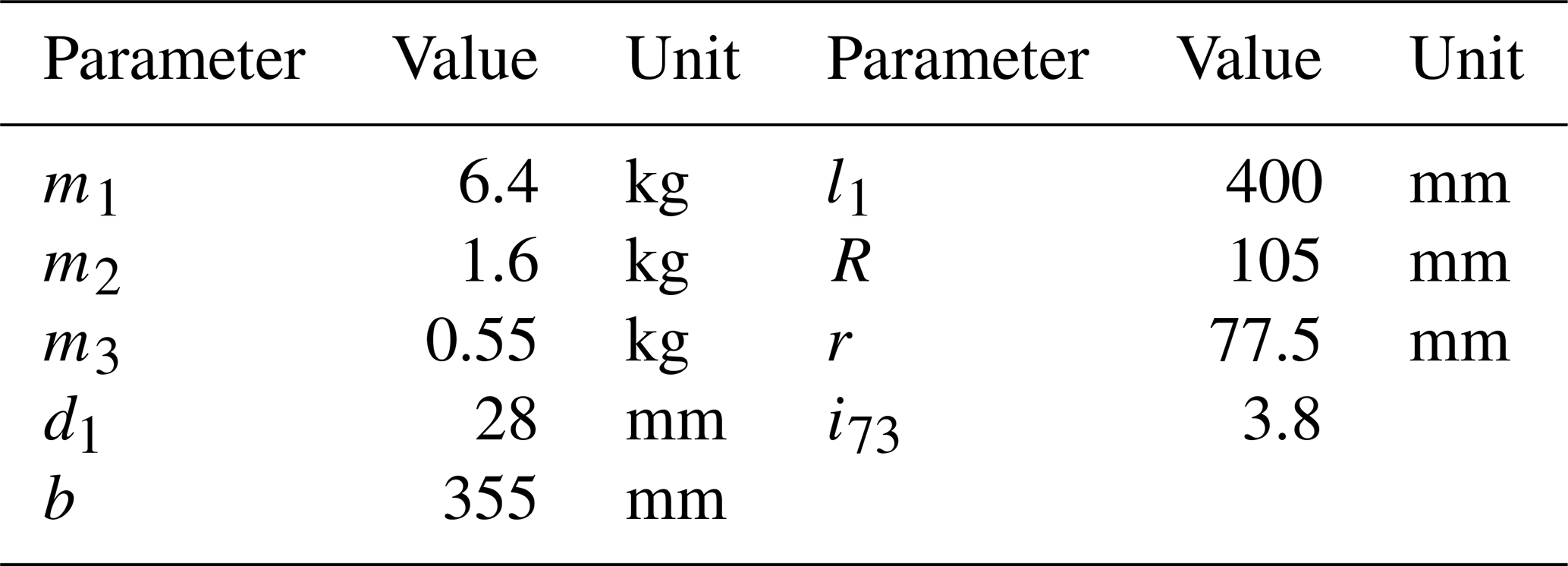
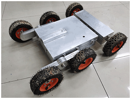
Based on the theoretical analysis presented above, using the structure parameters obtained in Table 1 with some essential adjustments required from mechanical component design, a physical prototype of the proposed robot was developed as shown in Fig. 19. The outer shell of the robot is machined with hard aluminum alloy with a total mass of 10.7 kg. The robot is powered by a 25.2 V battery and driven by four motors.
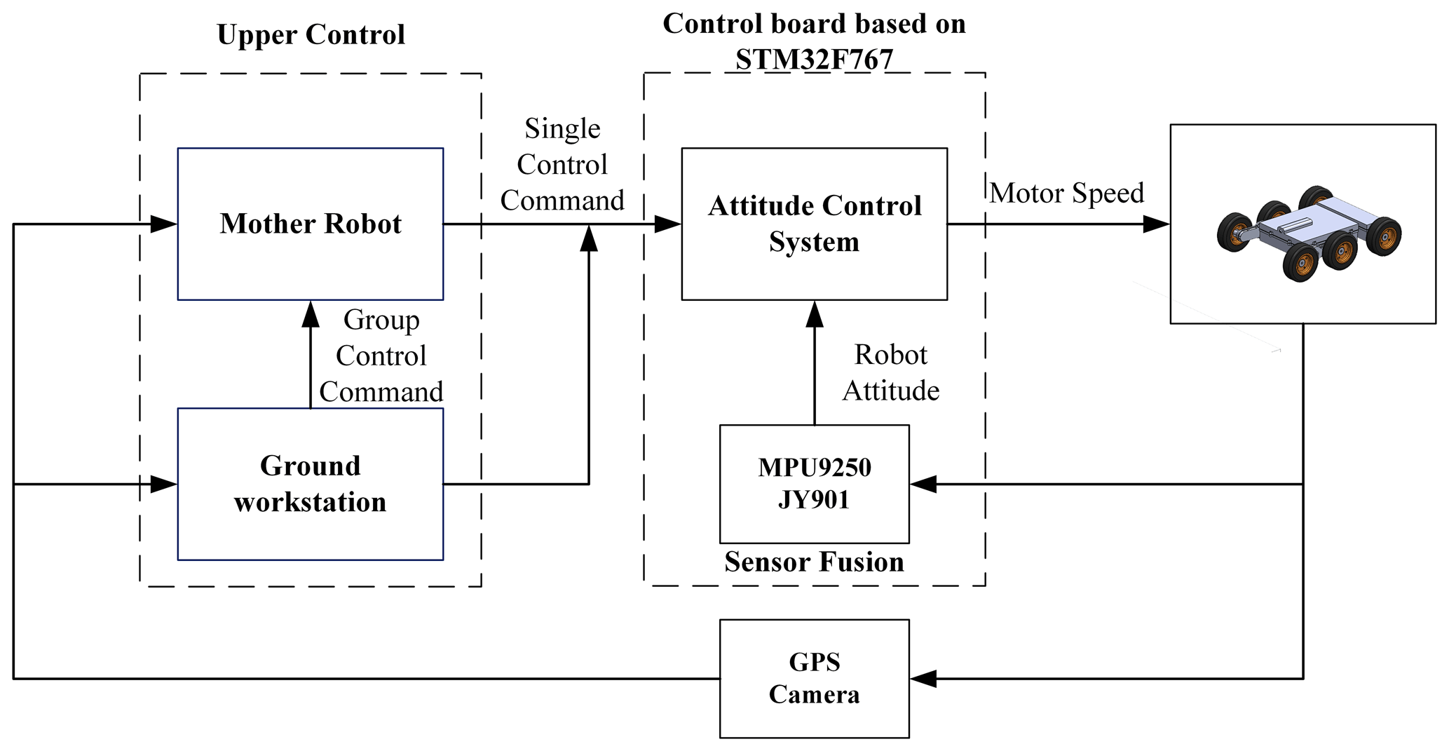
As shown in Fig. 20, the control system of the robot includes two controllers; one of them is a control board based on STM32F767, and the high-level controller is the mother robot or the ground workstation. The robot feeds back the information from the camera and GPS to the workstation and the parent robot. The ground workstation can send group control commands to the mother robot or directly send control commands to the robot. After receiving the commands, combined with the robot attitude measured by nine-axis sensors MPU9250 and JY901, the attitude control system sends speed commands to the motor.
4.2 Prototype field experiments
The surface of the planet is mostly sand and irregular rock terrain, which puts forward higher requirements for the terrain adaptability and obstacle surmounting ability of the robot. A video for the experiments is available in the Supplement of this paper. In order to test the motion performance of the robot in the environment similar to the planet's surface, as shown in Fig. 21, the motion stability of the robot is tested on sand (see Fig. 21a), grass (see Fig. 21b), and slopes (see Fig. 21c) respectively.
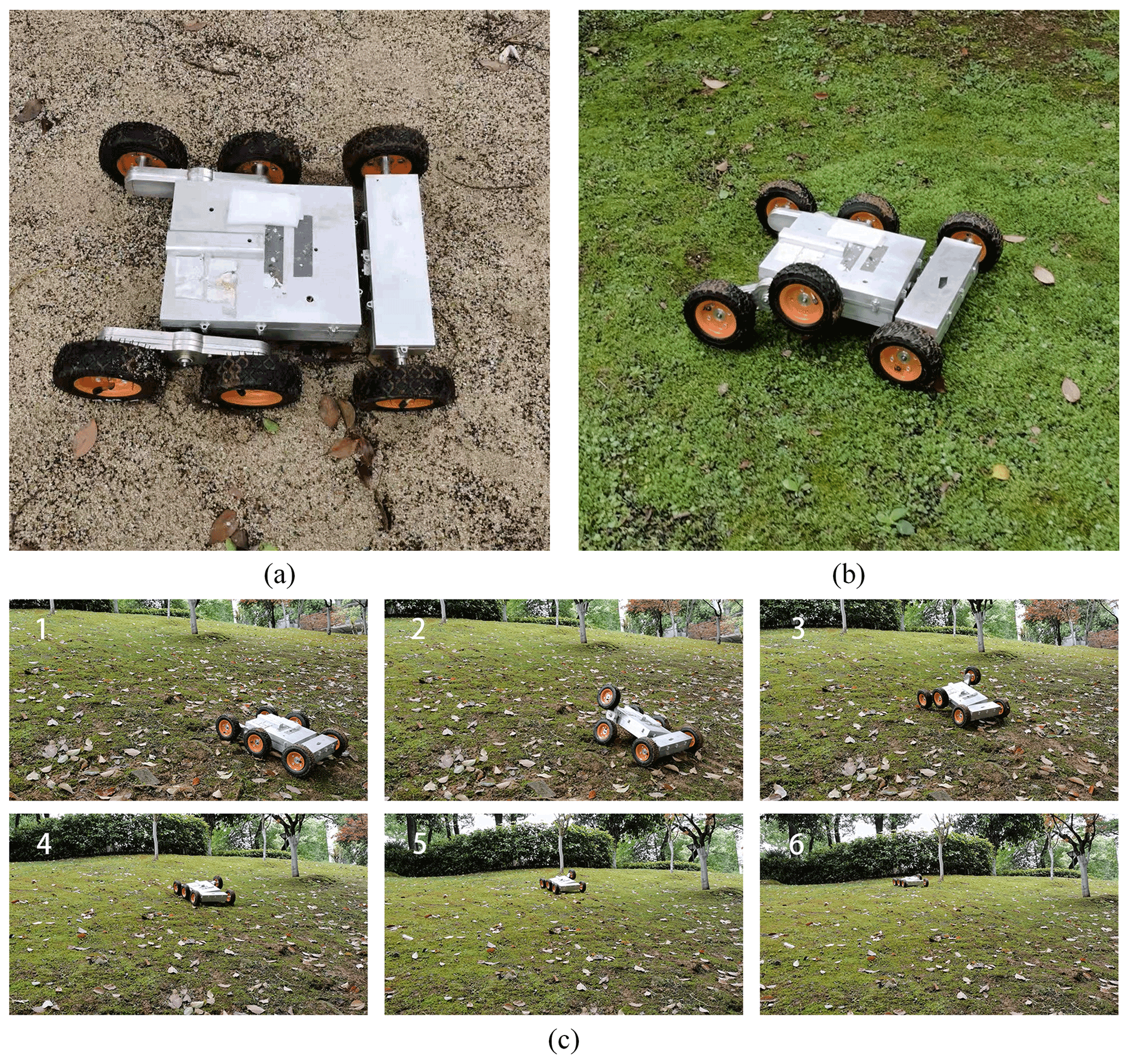
Figure 22 shows the curves of pitch angle and roll angle as the robot moves on grassland, sand, and slopes. The pitch angle and roll angle of the robot are recorded by the nine-axis gyroscope JY901. It can be seen from the diagram that when the robot moves on the grass (see Fig. 22a), the pitch angle and roll angle fluctuate in a small range due to the three-rocker-arm structure. However, when the robot moves on the sand (see Fig. 22b) and climbs the slope (see Fig. 22c), due to the existence of a large number of irregular obstacles, the robot will constantly turn the adaptive climbing rocker arms, which makes the pitch angle and roll angle fluctuate greatly.
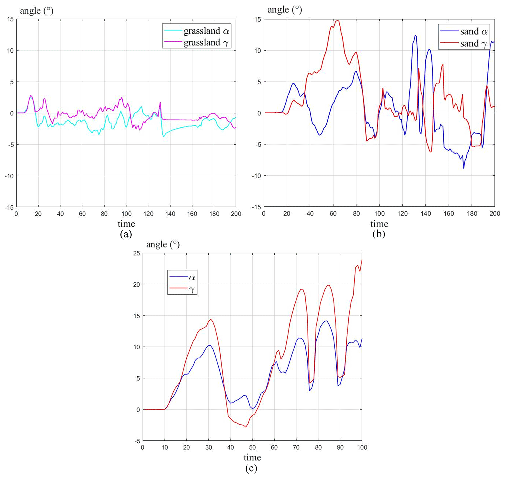
Figure 22The curves of pitch and roll angles as the robot moves on grassland, sand, and slopes.
In order to test the obstacle-crossing ability of the robot, a series of obstacle-crossing experiments were carried out on the robot. As shown in Fig. 23a, the experiment of the robot climbing over the 80 mm high vertical obstacle bilaterally was carried out. Figure 23b shows the curves of the pitch and roll angle of the robot as it climbs over the 80 mm vertical obstacle. It can be seen from the figures that the pitch angle of the robot increases first and then decreases when the robot touches the obstacle. Afterwards, the rear obstacle-crossing wheels of the robot lap onto the edge of the obstacle, the adaptive climbing rocker arms continue to turn, and the pitch angle continues to increase, with a maximum value of about 24∘. And because the robots cross the obstacle on both sides, the roll angle of the robot fluctuates around 0∘.
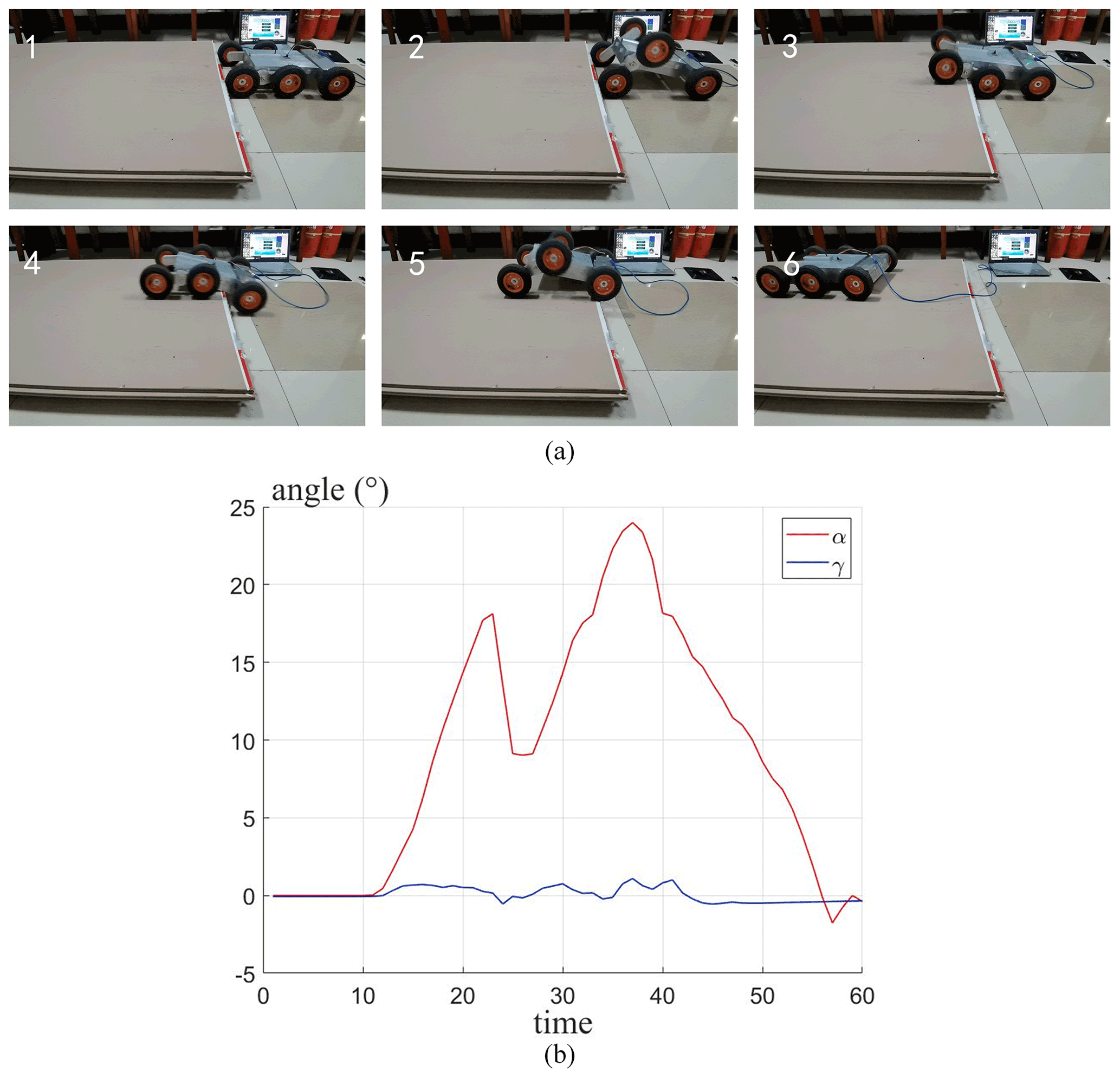
Figure 23Experiment of the robot climbing 80 mm vertical obstacle bilaterally and the curves of the pitch and roll angle of the robot obstacle crossing.
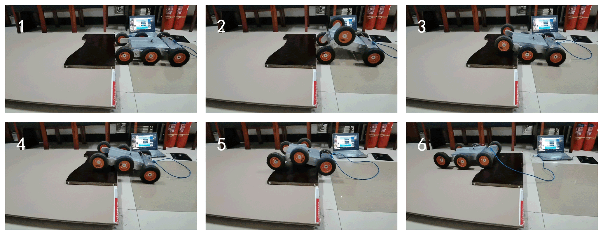
As shown in Fig. 24a, the experiment of the robot climbing over the 80 mm high vertical obstacle unilaterally was carried out. Figure 24b shows the curves of the pitch and roll angle of the robot as it climbs over the 80 mm vertical obstacle unilaterally. From Fig. 24b, in the process of obstacle crossing, the pitch angle and roll angle of the robot first increase, then decrease, and finally increase. The maximum value of the pitch angle is about 12∘, and that of the roll angle is about 22∘. The maximum pitch angle is only half of that (24∘) when the robot crosses the obstacle bilaterally, which shows that the three-rocker-arm structure does reduce the change of pitch angle when the robot crosses obstacles unilaterally.

Figure 24Experiment of the robot climbing 80 mm vertical obstacle unilaterally and the curves of the pitch and roll angle of the robot obstacle crossing.
In Figs. 23 and 24, the curves of pitch angle and roll angle of the robot unilateral and bilateral obstacle crossing are similar in shape to those of the simulation results in Fig. 12, which shows that the kinematic analysis of the obstacle-crossing process of the robot is in accordance with the actual situation.
To verify the correctness of the simulation results in Fig. 17, the experiment of the robot climbing over the 90 mm high vertical obstacle bilaterally was carried out. It can be seen from the figure that the robot can successfully climb over the 90 mm high obstacle, which means that the results in Fig. 17 have been basically validated.
Through the previous experiments, it can be seen that the robot has a certain passing ability for grassland, sand, and field slopes, which shows that the robot has good adaptability to uneven terrain. And the robot can also climb over vertical obstacles up to 90 mm by turning the adaptive climbing rocker arms. Therefore, the proposed robot should be competent for short-term and small-scale planetary exploration.
This paper proposed and developed a six-wheeled companion exploration robot with a self-adaptable obstacle-climbing mechanism. The robot is divided into front and rear bodies. The rear body and the adaptive climbing rocker arms on both sides of the robot can rotate freely relative to the front body, which together constitute the three-rocker-arm structure of the robot. Relying on the three-rocker-arm structure, the robot can adapt to different planetary surface environments and can also climb obstacles by turning the adaptive climbing rocker arms on both sides like crab legs.
The design requirements of the proposed robot were presented, and the mechanical design of the proposed robot was formulated. Based on the geometric parameter model of the robot, the terrain adaptivity and obstacle-crossing performance of the robot were analyzed. Further, through geometric and static analysis, the conditions of robot to climb over obstacles of different heights were obtained.
Based on the above design structure, an experimental prototype was developed, and field tests were subsequently carried out to prove the design concept, feasibility, maneuverability, and obstacle-crossing performance of the proposed mobile robot. The test results indicate that the robot can adapt to different terrain by its three-rocker-arm structure and keep the body stable in motion. And by turning the adaptive climbing rocker arms, the robot has the ability to climb over vertical obstacles up to 90 mm high. The experimental results are basically consistent with the previous analysis results, which proves that the design concept of the robot is reasonable.
Further research will focus on the cooperative work with the mother robot and other accompanying exploration robots. According to this aim, one of the main issues is realizing the feedback information process of the mother robot to the companion robot. Moreover, how the mother robot gives further instructions to the companion robot according to the feedback information is also currently an important research area.
| Geometrical parameters | |
| B | length between two wheels in the width direction |
| l | length of the front and rear bodies |
| R | radius of the adaptive climbing rocker arm |
| r | radius of the wheels (all the wheels are of the same dimension) |
| θl | swing angle of the left adaptive climbing rocker arm |
| θr | swing angle of the right adaptive climbing rocker arm |
| θf | rotation angle of rear body with respect to the coordinate frame in the X2–Z2 plane |
| α | pitch angle of the robot |
| β | steer angle of the robot |
| γ | roll angle of the robot |
| Mass parameters | |
| m1 | total mass of the front and rear body |
| m2 | mass of the adaptive climbing rocker arm |
| m3 | mass of the wheel |
| m | overall mass of the robot and |
| Coordinate parameters | |
| fixed inertia frame | |
| robot's front body coordinate frame | |
| robot's rear body coordinate frame | |
| left adaptive climbing rocker arm coordinate frame | |
| right adaptive climbing rocker arm coordinate frame | |
| 0T1 | transformation matrix of the robot coordinate frame relative to the fixed |
| coordinate frame | |
| 1T2 | transformation matrix of the rear body with respect to the robot coordinate frame |
| 1T3 | transformation matrix of the left adaptive climbing rocker arm with respect to the robot |
| coordinate frame | |
| 1T4 | transformation matrix of the right adaptive climbing rocker arm with respect to the |
| robot coordinate frame | |
| 1p1 | vector of the common centroid of the front and rear body in the robot coordinate frame |
| 1pl | vector of the centroid of the left adaptive climbing rocker arm in the robot coordinate frame |
| 1pr | vector of the centroid of the right adaptive climbing rocker arm in the robot coordinate frame |
| 1plw | vector of the centroid of the left tail walking wheel in the robot coordinate frame |
| 1prw | vector of the centroid of the right tail walking wheel in the robot coordinate frame |
| 1plf | vector of the centroid of the left front obstacle-crossing wheel in the robot coordinate frame |
| 1plr | vector of the centroid of the left rear obstacle-crossing wheel in the robot coordinate frame |
| 1prf | vector of the centroid of the right front obstacle-crossing wheel in the robot coordinate frame |
| 1prr | vector of the centroid of the right rear obstacle-crossing wheel in the robot coordinate frame |
| 1P0 | vector of the centroid of the whole robot in the robot coordinate frame |
| 0P0 | vector of the centroid of the whole robot in the fixed coordinate frame |
| Static parameters | |
| N1 | supporting force of the ground on the left front obstacle-crossing wheel |
| N2 | supporting force of the obstacle against the left front obstacle-crossing wheel |
| N3 | supporting force of the ground on the left tail walking wheel |
| N5 | supporting force of the obstacle on the robot body |
| f1 | friction force of the ground on the left front obstacle-crossing wheel |
| f2 | friction force of the obstacle against the left front obstacle-crossing wheel |
| f3 | friction force of the ground on the tail walking wheel |
| f5 | friction force of the edge of the obstacle on the robot body |
| T | torque of the adaptive climbing rocker arm's central gear shaft |
| i73 | transmission ratio between wheel shaft 7 and sun gear 3 in Fig. 3b |
| m1g | gravity of the robot's front and rear body |
| m2g | gravity of the robot's left rocker arm |
| m3g | gravity of the robot's left tail walking wheel |
Underlying research data are available upon request from the corresponding author.
The supplement related to this article is available online at: https://doi.org/10.5194/ms-12-1115-2021-supplement.
ZS carried out the experiments and wrote the original draft, ZL contributed to the conception of the study and designed the experiments, and GW and JS helped revise the paper and gave some advice on robot design. All authors have read and agreed to the published version of the paper.
The contact author has declared that neither they nor their co-authors have any competing interests.
Publisher’s note: Copernicus Publications remains neutral with regard to jurisdictional claims in published maps and institutional affiliations.
This work was done with support from the National Natural Science Foundation of China (grant no. 52075537, no. 52175069 and no. 52105039).
This research has been supported by the National Natural Science Foundation of China (grant no. 52075537, no. 52175069 and no. 52105039).
This paper was edited by Lionel Birglen and reviewed by two anonymous referees.
Altendorfer, R., Moore, N., Komsuoglu, H., Buehler, M., and Koditschek, D. E.: RHex: A Biologically Inspired Hexapod Runner, Auton. Robot., 11, 207–213, 2001.
Amiri, S., Sharaf, O., Almheiri, S., Alrais, A., Wali, M., Shamsi, Z. A., Qasim, I. A., Harmoodi, K. A., Teneiji, N. A., and Almatroushi, H. R.: Emirates Mars Mission (EMM) 2020 Overview, American Geophysical Union, Fall Meeting 2017, #P34B-08, December 2017, P34B-08, 2017AGUFM.P34B..08A, 2021.
Bruzzone, L. and Fanghella, P.: Mantis: hybrid leg-wheel ground mobile robot, Ind. Robot, 41, 26–36, 2014.
Bruzzone, L. and Quaglia, G.: Review article: locomotion systems for ground mobile robots in unstructured environments, Mech. Sci., 3, 49–62, https://doi.org/10.5194/ms-3-49-2012, 2012.
Cordes, F., Dettmann, A., and Kirchner, F.: Locomotion modes for a hybrid wheeled-leg planetary rover, 2011 IEEE International Conference on Robotics and Biomimetics, 7–11 December 2011, IEEE, Karon Beach, Thailand, Electronic ISBN 978-1-4577-2138-0, Print ISBN 978-1-4577-2136-6, 2011.
Deng, Z. Q., Suo-Jun, L. I., and Gao, H. B.: Research and Development of Passive Rocker Suspension of Planetary Exploration Rover, Yuhang Xuebao/Journal of Astronautics, 29, 1695–1700+1722, 2008.
Gao, H.: Key technology of moving system of lunar rover with planetary wheel, Chin. J. Mech. Eng., 42, 157–161, https://doi.org/10.3901/JME.2005.12.156, 2005.
Harrison, D. A., Ambrose, R., Bluethmann, B., and Junkin, L.: Next Generation Rover for Lunar Exploration, 2008 IEEE Aerospace Conference, 1–8 March 2008, IEEE, Big Sky, MT, USA, https://doi.org/10.1109/AERO.2008.4526234, 2008.
He, Q. S.: On Space Policy Trend of the Trump Administration, Journal of Shanghai Jiaotong University, 026, 25–33, 2018.
Herbert, S. D., Drenner, A., and Papanikolopoulos, N.: Loper: A quadruped-hybrid stair climbing robot, 2008 IEEE International Conference on Robotics & Automation, 19–23 May 2008, IEEE, Pasadena, CA, USA, https://doi.org/10.1109/ROBOT.2008.4543303, 2008.
Kozma, R., Hunstberger, T., Aghazarian, H., and Freeman, W. J.: Implementing intentional robotics principles using SSR2K platform, 2007 IEEE/RSJ International Conference on Intelligent Robots & Systems, 29 October–2 November 2007, IEEE, San Diego, CA, USA, https://doi.org/10.1109/IROS.2007.4399490, 2007.
Kubota, T., Kuroda, Y., Kunii, Y., and Nakatani, I.: Small, light-weight rover “Micro5” for lunar exploration, Acta Astronau., 52, 447–453, https://doi.org/10.1016/S0094-5765(02)00187-X, 2003.
Lacagnina, M., Muscato, G., and Sinatra, R.: Kinematics, dynamics and control of a hybrid robot Wheeleg, Robotics Autonomous Systems, 45, 161–180, 2003.
Lauria, M., Piguet, Y., and Siegwart, R.: Octopus – An Autonomous Wheeled Climbing Robot, The Fifth International Conference on Climbing and Walking Robots (CLAWAR), 25–27 September 2002, Paris, France, https://doi.org/10.3929/ethz-a-010098355, 2002.
Li, C., Han, L., Yuan, S., and Zhang, Y.: Optimization Design and Simulation of Six branched Wheel-Legged Robot, Manned Spaceflight, 25, 37–41, https://doi.org/10.16329/j.cnki.zrht.2019.01.006, 2019.
Lindemann, R. A. and Voorhees, C. J.: Mars Exploration Rover mobility assembly design, test and performance, 2005 IEEE International Conference on Systems, 12–12 October 2005, IEEE, Waikoloa, HI, USA, https://doi.org/10.1109/ICSMC.2005.1571187, 2006.
Liu, C.: Research on obstacle-performance of articulated-track inspection robot under complex environment, University of South China, master thesis, 2018.
Liu, F. H.: A five wheeled lunar robot and its characteristics analysis, J. Mach. Design, 15–18, https://doi.org/10.3969/j.issn.1001-2354.2001.05.006, 2001a.
Liu, F. H.: Kinematic Modeling of A Five-Wheel Articulated Lunar Robot, Robot, 23, 6, https://doi.org/10.3321/j.issn:1002-0446.2001.06.001, 2001b.
Lu, D., Dong, E., Liu, C., X, M., and Yang, J.: Design and development of a leg-wheel hybrid robot “HyTRo-I”, 2013 IEEE/RSJ International Conference on Intelligent Robots and Systems, 3–7 November 2013, IEEE, Tokyo, Japan, https://doi.org/10.1109/IROS.2013.6697232, 2013.
Nelson, C. A.: Self-Adaptive Underactuated Hybrid Rolling/Walking Locomotion, ASME 2012 International Design Engineering Technical Conferences and Computers and Information in Engineering Conference, Self-Adaptive, Underactuated Hybrid, Rolling/Walking Locomotion, 12–15 August 2012, Chicago, IL, USA, https://doi.org/10.1115/DETC2012-71394, 2012.
Oderio, R. and Quaglia, G.: Design of the small mobile robot Epi.q-2, Proceedings of the XIX Congress AIMETA – Italian Association for Theoretical and Applied Mechanics, Ancona, Italy, 14–17 September 2009.
Ouyang, Z. Y., Zou, Y. L., Li, C. L., Liu, J. Z., and Xu, L.: Lunar exploration and containable development for human society, Bulletin of Mineralogy Petrology Geochemistry, 22, 328–333, https://doi.org/10.3969/j.issn.1007-2802.2003.04.009, 2003.
Quaglia, G. and Nisi, M.: Design and Construction of a New Version of the Epi.q UGV for Monitoring and Surveillance Tasks, ASME 2015 International Mechanical Engineering Congress and Exposition, 13–19 November 2015, Houston, Texas, https://doi.org/10.1115/IMECE2015-50163, 2015.
Quaglia, G., Bruzzone, L., Oderio, R., and Razzoli, R. P.: Epi.q Mobile Robots Family, Asme International Mechanical Engineering Congress & Exposition, Denver (USA), 7, 1165–1172, https://doi.org/10.1115/imece2011-62674, 2011.
Sunspiral, V., Wheeler, D. W., Chavez-Clemente, D., and Mittman, D.: Development and field testing of the FootFall planning system for the ATHLETE robots, J. Field Robot., 29, 483–505, 2012.
Volpe, R., Balaram, J., and Ohm, T. J. A. R.: Rocky 7: A Next Generation Mars Rover Prototype, Advanced Robotics, 11, 341–358, 1997.
Waldron, K. J., Eich, M., Grimminger, F., and Kirchner, F.: Adaptive compliance control of a multi-legged stair-climbing robot based on proprioceptive data, Ind. Robot, 36, 331–339, 2009.
Weisbin, C. R., Lavery, D., and Rodriguez, G.: Robotics Technology for Planetary Missions into the 21st Century, https://doi.org/10.1.1.30.6390, 1997.
Wettergreen, D., Jonak, D., Kohanbash, D., and Teza, J.: Design and field experimentation of a prototype Lunar prospector, The International journal of robotics research, 29, 1550–1564, https://doi.org/10.1177/0278364910370217, 2010.
Yu, W. Z.: Design of Lunar Rover With V.C.M and Research on Performance of Mobility, Harbin Institute of Technology, master thesis, https://doi.org/10.7666/d.D259553, 2009.
Yue, N., Li, C., Han, L. L., and Zhang, Y. X.: Scheme design of Modular Wheel-legged Lunar Robot, Manned Spaceflight, 25, 667–672, 2019.
Zakrajsek, J. J., Mckissock, D. B., Woytach, J. M., Zakrajsek, J. F., Oswald, F. B., Mcentire, K. J., Hill, G. M., Abel, P., Eichenberg, D. J., and Goodnight, T. W.: Exploration Rover Concepts and Development Challenges, in: A Collection of Technical Papers – 1st Space Exploration Conference: Continuing the Voyage of Discovery Oriando, Florida, 1, 258–280, https://doi.org/10.2514/6.2005-2525, 2005.
Zhang, Y. X., Huang, J., and Han, L. L.: Researche status of planetary surface mobile exploration robots: Review, Acta Aeronautica et Astronautica Sinica, 42, 62–79, 2021.
- Abstract
- Introduction
- Structure and principle of the companion robot
- Modeling and analysis of robot locomotion performance
- Prototype development and field experiments
- Conclusions
- Appendix A: Nomenclature
- Code and data availability
- Author contributions
- Competing interests
- Disclaimer
- Acknowledgements
- Financial support
- Review statement
- References
- Supplement