the Creative Commons Attribution 4.0 License.
the Creative Commons Attribution 4.0 License.
 | 17 Dec 2021
Establishment and analysis of nonlinear frequency response model of planetary gear transmission system
Yue Bi
Zhen-Bin Liu
Xiao-Long Zhao
Based on the lumped parameter theory, a nonlinear bending torsion coupling dynamic model of planetary gear transmission system was established by considering the backlash, support clearance, time-varying meshing stiffness, meshing damping, transmission error and external periodic excitation. The model was solved by the Runge–Kutta method, the dynamic response was analyzed by a time domain diagram and phase diagram, and the nonlinear vibration characteristics were studied by the response curve of the speed vibration displacement. The vibration test of the planetary gearbox was carried out to verify the correctness of frequency domain response characteristics. The results show that the vibration response in the planetary gear system changes from a multiple periodic response to a single periodic response with the increase in input speed. Under the action of the backlash, time-varying meshing stiffness and meshing damping, the speed vibration displacement response curves of internal and external meshing pairs appear to form a nonlinear jump phenomenon and have a unilateral impact area, and the system presents nonlinear characteristics. The nonlinear vibration of the system can be effectively suppressed by decreasing the mesh stiffness or increasing the mesh resistance, while the vibration response displacement of the system increases by increasing the external exciting force, and the nonlinear characteristics of the system remain basically unchanged. The backlash is the main factor affecting the nonlinear frequency response of the system, but it can restrain the resonance of the system in a certain range. The spectrum characteristics of the vibration displacement signal of the planetary gearbox at different speeds are similar to the simulation results, which proves the validity of the simulation analysis model and the simulation results. It can provide a theoretical basis for the system vibration and noise reduction and a dynamic structural stability design optimization.
- Article
(7873 KB) - Full-text XML
- BibTeX
- EndNote


Planetary gear transmission has been widely used in aircraft and vehicles because of its high load and large transmission ratio. However, due to its prominent nonlinear vibration problem, it is very prone to failure phenomena such as tooth fatigue pitting, tooth root crack and tooth or shaft fracture, which affects the operation accuracy, transmission efficiency and service life of the equipment.
Many scholars have done a lot of research on the nonlinear vibration of the planetary transmission system. Sun and Hu (2003) solved the bending and torsion model of planetary gear, considering the transverse support of solar shaft by the harmonic balance method, and verified the analysis results with a numerical simulation using the Runge–Kutta method. Tang et al. (2020) used the numerical integration method to analyze the effects of input speed, backlash, support clearance and damping ratio on the nonlinear dynamic characteristics of a planetary transmission system. Bahk and Parker (2011) solved and analyzed the vibration response and variation law of the system through perturbation analysis within the meaningful meshing frequency range and found that the external torque cannot inhibit the occurrence of the tooth falling off. Li et al. (2014) solved the multi-stage planetary dynamics model, based on the variable step size Gill numerical integration method, and analyzed the bifurcation characteristics of the system using the dynamic graphics tool. Li et al. (2016) considered the dynamic and static clearance and the frequency response characteristics of the gear system, and the influence of dynamic internal and external excitation parameters on the dynamic characteristics of the gear system were analyzed by using the analytical method. Li et al. (2015), in the study of the gear transmission system in a shearer, expressed and estimated the tooth clearance in the system by fractal expression, and the vibration characteristics of the system are studied theoretically and experimentally. Li et al. (2020) analyzed the theoretical fault characteristic frequency, combined the fault characteristic frequency of each component and diagnosed each combined fault based on Fourier spectrum analysis. Xiao et al. (2020) used the improved energy method to calculate the time-varying meshing stiffness of normal and cracked gears. Zhou et al. (2016) established a translational torsional coupling dynamic model, considering the time-varying meshing stiffness, comprehensive meshing error and backlash. Xiang et al. (2020a) analyzed the vibration response and bifurcation characteristics of the two-stage planetary gear train transmission system of a wind turbine gearbox. Jian et al. (2021) comprehensively considered the influence of the modification coefficient and time-varying meshing stiffness; based on the dynamic theory, the dynamic model of planetary gear system was established, and the thermal electrohydrodynamic lubrication characteristics of the modified gear system under vibration were analyzed. Chen et al. (2021) established the dynamic model of the planetary gearbox, considering the clearance of the planetary gear, sun gear and carrier bearing. Liu et al. (2020) studied and analyzed the influence of the flexibility of the ring gear and the support stiffness of the ring gear and the sun gear on the vibration characteristics of the planetary gear train. Wang et al. (2020) proposed a method to analyze the vibration and stress characteristics of the ring gear and analyzed the vibration and stress characteristics of the thin-walled ring gear. Li et al. (2020) established a multi-body dynamic model of the ring gear elastic support planetary gear system and discussed the influence of ring gear radial support stiffness on system vibration. Wang et al. (2021) proposed a vibration data analysis method based on the time synchronization average of enhanced planetary gears. Zhang et al. (2021) carried out a free modal test on the planetary transmission mechanism with the free modal test method and carried out a modal analysis with the finite element method. Xiang et al. (2020b) established a nonlinear model of a multi-stage gear transmission system, considering meshing stiffness, gear comprehensive error and backlash, and analyzed the nonlinear dynamic response of the system with excitation frequency and support stiffness as bifurcation parameters. Saghafi and Farshidianfar (2016) used the Melnikov method to give an analytical method to eliminate the chaos of the gear system under external control excitation. Yang et al. (2019) established a 3 degrees of freedom spur gear pair model, considering the nonlinearity of the backlash and bearing clearance, and studied the influence of tooth crack on the vibration characteristics of nonlinear spur gear system. Liu et al. (2017) studied the dynamic response of spur gear pair system and the interaction between the bearing clearance and backlash. Wang et al. (2018) obtained the bifurcation diagram and a Lyapunov exponent curve of the spur gear transmission system with the numerical method and analyzed the mechanism of the chaotic evolution of the gear transmission system. Fan et al. (2020) established a rigid flexible coupling dynamic model of the planetary gear transmission system, considering the flexibility of the inner ring gear and sun shaft, and calculated the dynamic response of the system with a numerical algorithm. Wang (2019) simulated the wear failure of the gear transmission system through the change of gear backlash and studied the bifurcation diagram of the system when the backlash increased.
To sum up, at present, the research on the nonlinear characteristics of the planetary transmission system mainly focuses on the bifurcation characteristics and fault analysis, while the research on the nonlinear frequency response characteristics of planetary gear system is less. In order to study the frequency response characteristics of the nonlinear system of the planetary gearbox under the action of multiple clearances, based on the lumped parameter theory and comprehensively considering the backlash, a nonlinear dynamic model of the bending torsion coupling of the planetary gear transmission system is established, including time-varying meshing stiffness, meshing synthesis error, external periodic excitation and other nonlinear factors. The model is solved by a numerical method, and the nonlinear dynamic characteristics and frequency response characteristics of the system are analyzed by the time domain diagram and phase diagram.
Using the lumped parameter method, the bending torsion coupling nonlinear vibration model of planetary gear transmission system, as shown in Fig. 1, is established.
When establishing the dynamic model, three coordinate systems, namely OXYZ, Oxyz and Onxnynzn, are defined based on the sun gear, planet carrier and central axis of the planet gear. OXYZ is the fixed coordinate system, and Oxyz and Onxnynzn are the rotational speed. ωc is a moving coordinate system rotating around the axis O, and their coordinate axes are parallel to each other. The tooth surface friction is not considered in the bending torsion coupling nonlinear vibration model of the system. The inner ring gear is kept fixed. The influence of the input shaft of the sun gear and the output shaft of the planet carrier will temporarily not be considered. kbjx, cbjx and bbjx represent support stiffness, support damping and the half-support clearance of the x axis. kbjy, cbjy and bbjy represent the support stiffness, support damping and half-support clearance of the y axis. j = s, p and c represent the sun gear, planet gear and planet carrier, respectively. kspi, cspi, bspi and espi represent the meshing stiffness, meshing damping, backlash and comprehensive transmission error of the meshing direction of the planet gear and the sun gear. krpi, crpi, brpi and erpi indicate the meshing stiffness, meshing damping, backlash and comprehensive transmission error of the meshing direction of planet gear and inner ring gear. Here, i=1, 2 and 3 denote the ith meshing pair.
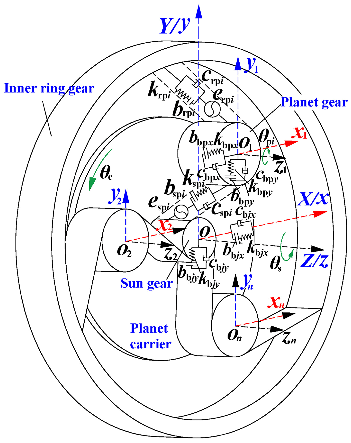
Figure 1Bending torsion coupling the nonlinear vibration model of the planetary gear transmission system.
The model has 3N+6 degrees of freedom, where N is the number of the planet gear. The generalized displacement array X can be expressed as follows:
Here, xj, yj and θj are the vibration displacement, where j is s, pi and c.
The differential equations of the sun gear, the planet gear, and the planet carrier can be expressed as follows:
Here, T1 is the input torque. T2 is the output torque. φpi is the position angle of the ith planet gear. mj is the component mass. Ij is the moment of inertia of the component. rbj is the radius of the base circle. j is s, p and c. φspi and φrpi are the angles between the y axis of the ith planet gear and its outer meshing plane and inner meshing plane, respectively. δspi and δrpi are the vibration displacement on the outer meshing line and the inner meshing line, respectively. δcpix and δcpiy are the vibration displacement of the ith planet gear relative to the planet carrier in each axis. i=1, 2, 3. f(δ) is the backlash nonlinear function.
The relative displacement in the direction of external meshing pair is defined as follows:
The relative displacement in the direction of internal meshing pair is defined as follows:
The ith planet gear is on the x and y axis, relative to the planet carrier, as follows:
The system dynamics equation is dimensionless, and the nominal scale of and τ=ωnt, of the order of . ωn is the excitation frequency. When the input speed n is given, the following expression can be obtained:
Here, Zs and Zr are the number of sun gear teeth and inner ring gear teeth, respectively, is the absolute rotation frequency of the sun gear, and fc is the rotation frequency of planet carrier. The calculation formula is as follows:
The formula of ωn is as follows:
Here, mes and mep are the equivalent masses of the sun gear and planet gear, respectively, , and .
Other dimensionless physical quantities are defined as follows:
The external exciting force F1 is expanded by Fourier series, and the order is the same as the stiffness, which can be expressed as follows:
Here, fl is the lth harmonic coefficient of the input dynamic excitation expanded by Fourier series.
By introducing the relative displacement and dimensionless physical quantity defined above into the differential equation, the dimensionless differential equation with as the variable is obtained as follows:
The dimensionless differential equations of the sun gear and the planet gear are expressed as follows:
The dimensionless differential equation of the internal and external meshing pair can be expressed as follows:
4.1 Frequency response characteristics analysis
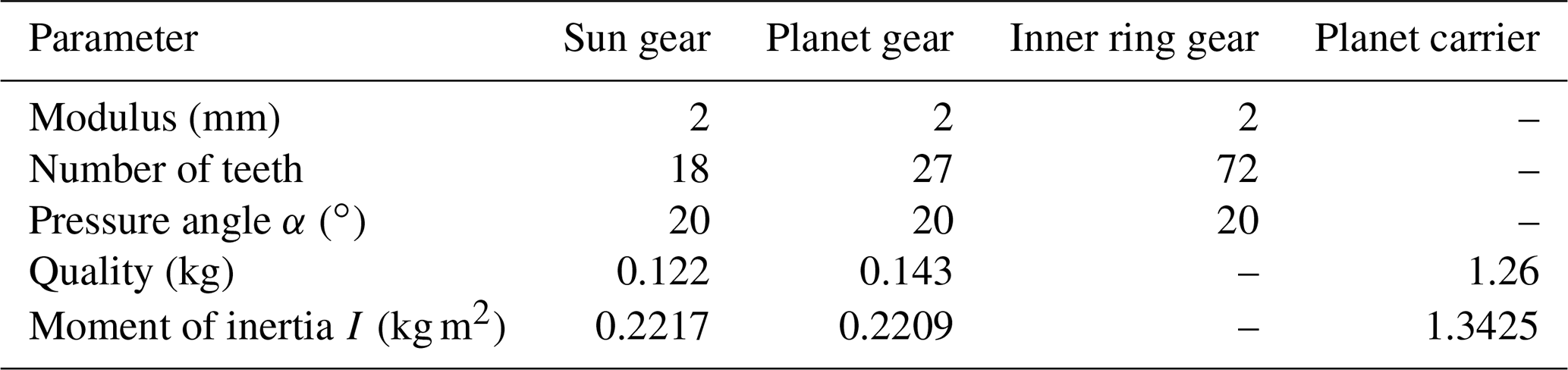
The basic parameters are shown in Table 1.
The time-varying meshing stiffness krpi and kspi can be expressed with the following equations:
Here, ksm and krm are the average meshing stiffness. ka and kb are the harmonic coefficients of the meshing stiffness. λa and λb are the phase angles of the meshing stiffness.
The comprehensive transmission errors erpi and espi can be expressed with the following equations:
Here, es and er are the fluctuating mean values of the meshing comprehensive errors. ea and eb are harmonic coefficients of the meshing comprehensive errors. φa and φb are the phase angles of the meshing comprehensive errors.
The nonlinear function of the meshing backlash and support clearance can be defined as follows:
The damping coefficients can be expressed as follows:
Here, ξrpi and ξspi are the meshing damping ratios of the ith internal and external meshing pairs.
The harmonic parameters of each excitation term in the external meshing pair can be expressed as follows: L=3, N=3, F1=1, f1=0.05, f2=0.02, f3=0.01, e1=0.05, e2=0.02, e3=0.01, k1=0.1, k2=0.04, and k3=0.05. The harmonic parameters of each excitation term in the internal meshing pair can be expressed as follows: L=3, N=3, F1=1, f1=0.05, f2=0.02, f3=0.01, e1=0.05, e2=0.02, e3=0.01, k1=0.05, k2=0.02, and k3=0.01.
The average meshing stiffness of the internal and external gear pairs is calculated according to the China national product standard (GB/T 3480-2019). The calculation results are shown in Table 2 and are verified by the Ishikawa method (Mao et al., 2021). The calculated meshing stiffness is expanded by a Fourier series to obtain the internal and external time-varying meshing stiffness curve, as shown in Fig. 2.

The Runge–Kutta method is used to solve the differential equation to obtain the vibration response of the internal and external meshing pairs of the planetary system at different speeds, as shown in Figs. 3 and 4.

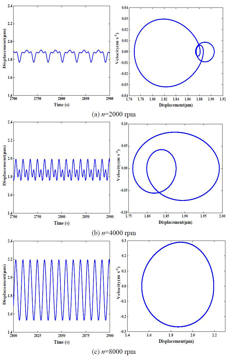
The time history diagram and phase plane diagram of the external meshing pair at n=2000, n=4000 and n=8000 rpm (revolutions per minute) is shown in Fig. 3. The vibration response of the system at each speed shows the period responses of 3 times, 2 times and 1 time, respectively. Similarly, at three input speeds, the time history diagram and phase plane diagram of the internal meshing pair in Fig. 4 show similar vibration response laws, and the vibration response tends, from multiple periods, to form a single period vibration.
Figure 5 shows the vibration displacement frequency response curve of the external and internal meshing pairs with the change in speed. The vertical axis, Xmax and Xmin, are the maximum and minimum vibration displacement, respectively, and the horizontal axis, n, is the input speed.
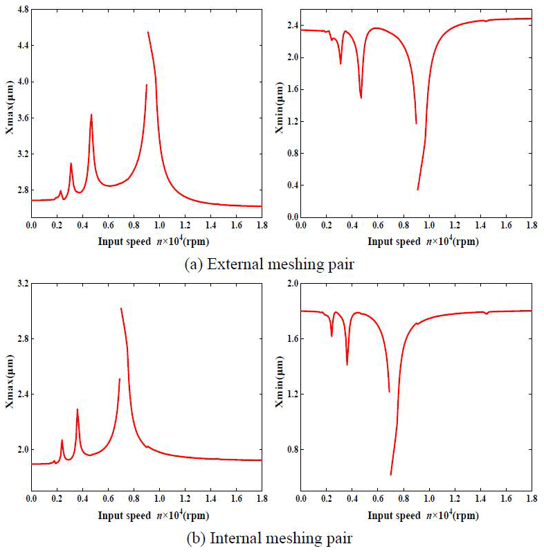
Figure 5a shows that under the action of various kinds of excitation, including clearance, the vibration displacement frequency response of the external meshing pair jumps at n=9100 rpm, the system transits from a non-impact state to unilateral impact state, and the system is in unilateral impact state in the speed range of n = 9100–9700 rpm. Figure 5b shows that the vibration displacement frequency response of the internal meshing pair jumps at n=7100 rpm, and the range of unilateral impact speed is n = 7100–7700 rpm. At the same time, in addition to the main resonance peak, the frequency response curves of the internal and external meshing pairs also form the resonance sub-peak, which leads to the super harmonic vibration response of the system.
4.2 Influence of excitation parameters on frequency response characteristics
4.2.1 Meshing stiffness influence
Based on the basic and dynamic parameters in Tables 1 and 2, taking , the other excitation parameters are L=3, N=3, F1=1, f1=0.05, f2=0.02, f3=0.01, e1=0.05, e2=0.02, and e3=0.01. The vibration displacement response curves under the three kinds of time-varying meshing stiffness are obtained and shown in Fig. 6. The harmonic components of the time-varying meshing stiffness are k1=0, k2=0, k3=0, k1=0.05, k2=0.02, k3=0.01 and k1=0.1, k2=0.04, and k3=0.05.
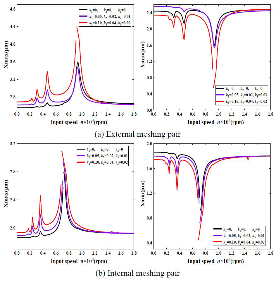
Figure 6 shows that the harmonic component of the variable meshing stiffness decreases, the jumping phenomenon of the vibration response curves of the external and internal meshing pairs decreases, the speed range of the system with unilateral impact decreases, and the nonlinear vibration of the system is significantly suppressed.
4.2.2 Meshing damping influence
Given that the meshing damping ratio ξsp1 is equal to 0.025, 0.04 and 0.1, respectively, we define ξrp1=ξsp1. In addition, the harmonic component of external meshing is k1=0.1, k2=0.04, and k3=0.02. The internal harmonic component is k1=0.05, k2=0.02, and k3=0.01. The other excitation parameters are L=3, N=3, F1=1, f1=0.05, f2=0.02, f3=0.01, e1=0.05, e2=0.02, and e3=0.01. Based on the above parameters, the solution result of the vibration displacement response curve of the system is shown in Fig. 7.
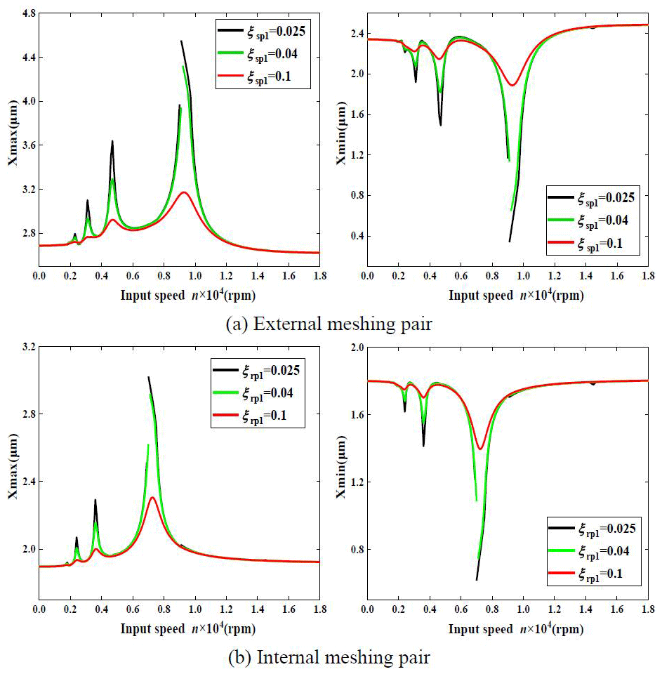
Figure 7 shows that the nonlinear jump phenomenon in the vibration displacement response curves of the external and internal meshing pairs decreases with the increase in meshing damping and, finally, disappears. There is no unilateral impact, and the system vibration presents linear characteristics.
4.2.3 External exciting force influence
When the external exciting force F1 is equal to 1, 1.25 and 1.5, respectively, the vibration displacement response curve of the external and internal meshing pairs is as shown in Fig. 8. The other parameters are L=3, N=3, f1=0.05, f2=0.02, f3=0.01, ξsp1=0.025, ξrp1=0.025, e1=0.05, e2=0.02, e3=0.01, k1=0.1, k2=0.04, and k3=0.02.
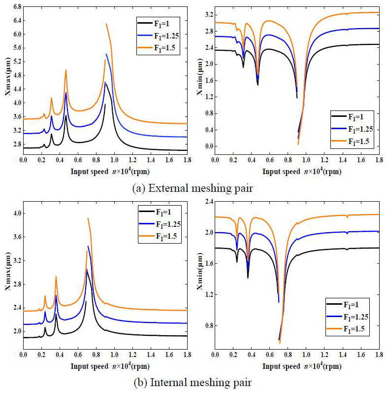
Figure 8 shows that the amplitude of the vibration displacement response curve of the external and internal meshing pairs increases obviously with the increase in the external exciting force, while the nonlinear jump phenomenon and unilateral impact area remain basically unchanged, and the nonlinear characteristics of the system are less affected by an external exciting force.
4.2.4 Backlash influence
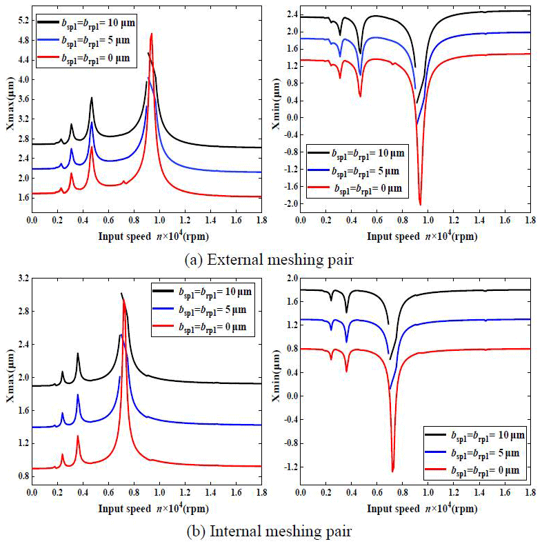
Figure 9 shows the speed vibration displacement response curves of the internal and external meshing pairs under different backlash and taking µm, µm, and µm. The other excitation parameters can be expressed as L=3, N=3, F1=1, f1=0.05, f2=0.02, f3=0.01, ξsp1=0.025, ξrp1=0.025, e1=0.05, e2=0.02, e3=0.01, k1=0.1, k2=0.04, and k3=0.02.
Figure 9 shows that when the backlash is zero, the vibration response curve of the system is linear. When the backlash is not zero, the vibration displacement response curves of the external and internal meshing pairs appear to have a jumping phenomenon and a unilateral impact area. At the same time, with the increase in the backlash, the nonlinear characteristics of the system are enhanced, and compared with zero backlash, the main resonance peak of the vibration response curve of the system is suppressed.
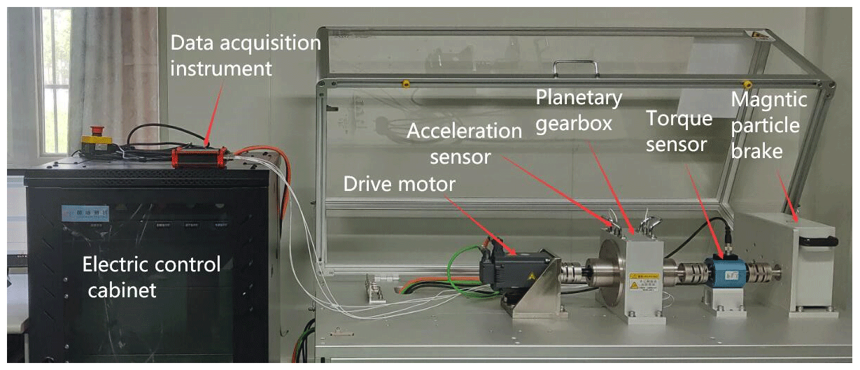
The vibration test bench is shown in Fig. 10. The main components include the electric control cabinet, data acquisition instrument, drive motor, planetary gearbox, acceleration sensor, torque sensor and magnetic particle brake. The basic parameters of the planetary gearbox are shown in Table 1.
The characteristic frequency is calculated with Eqs. (9), (10) and (11) and is shown in Table 3.
Figures 11, 12 and 13 are the time domain and frequency domain diagrams of the vibration acceleration signal of the planetary gearbox when the motor selects the uniform speed mode of 1500, 2000 and 2500 rpm, respectively.
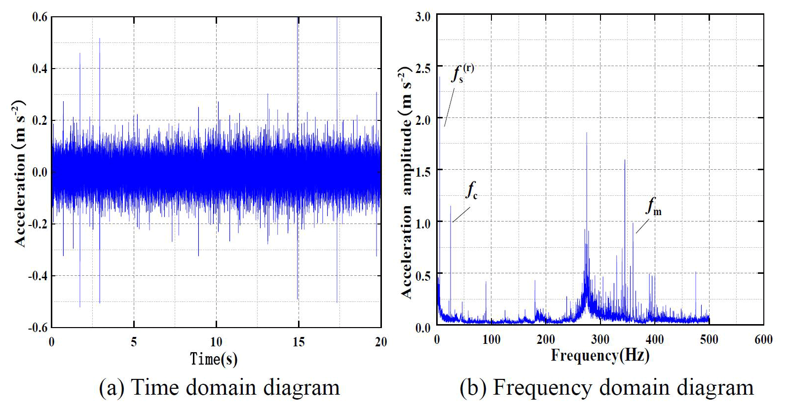
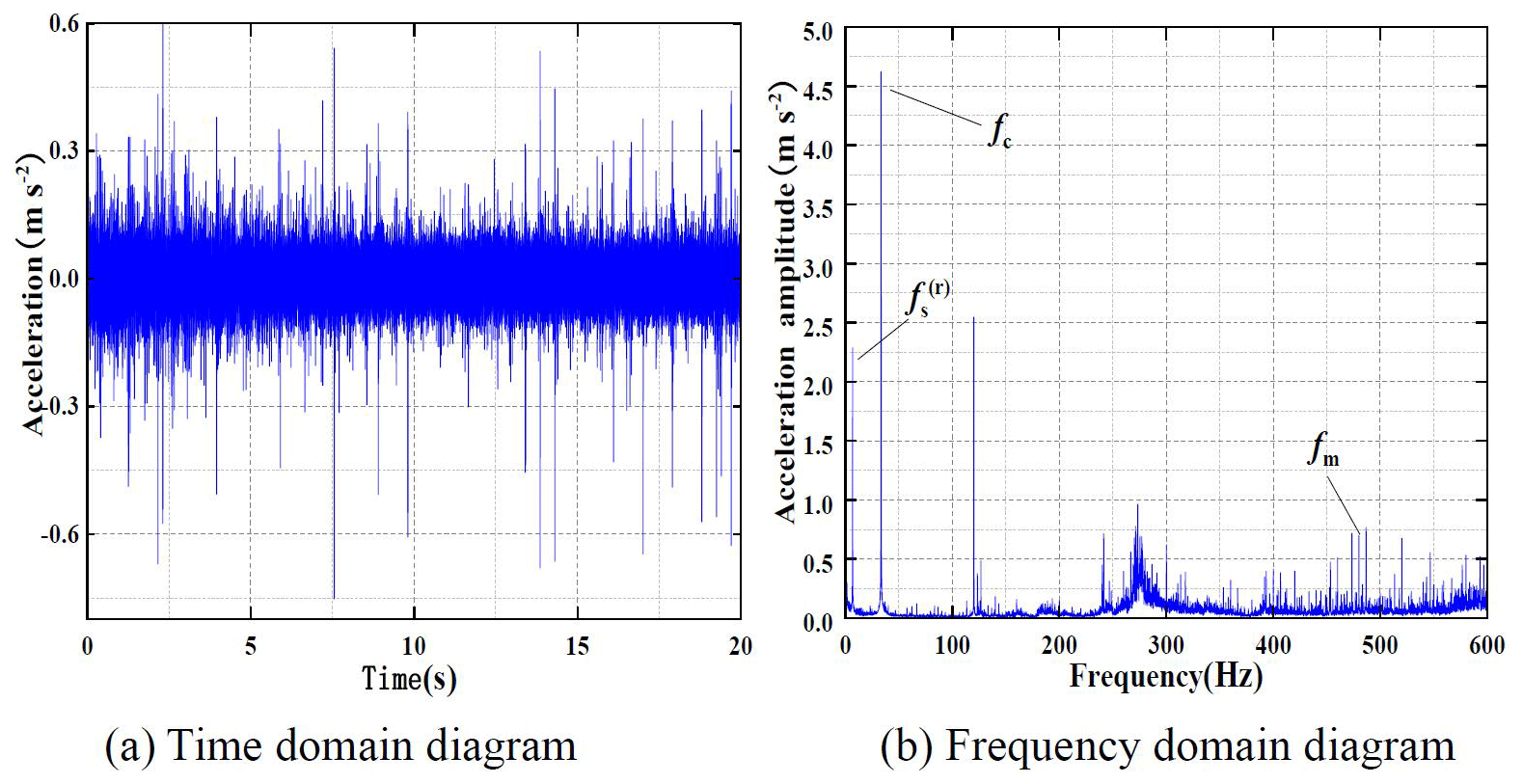
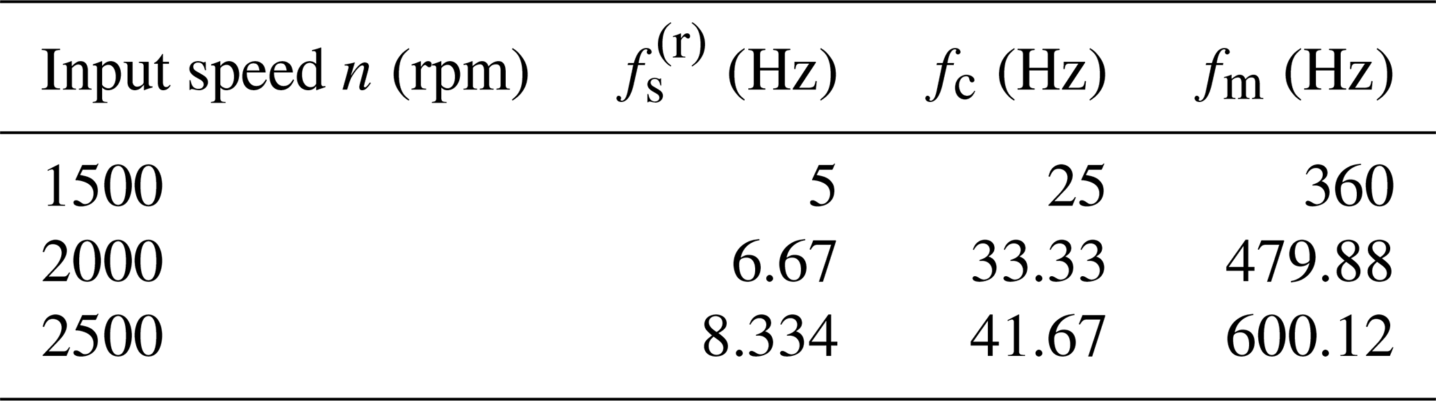
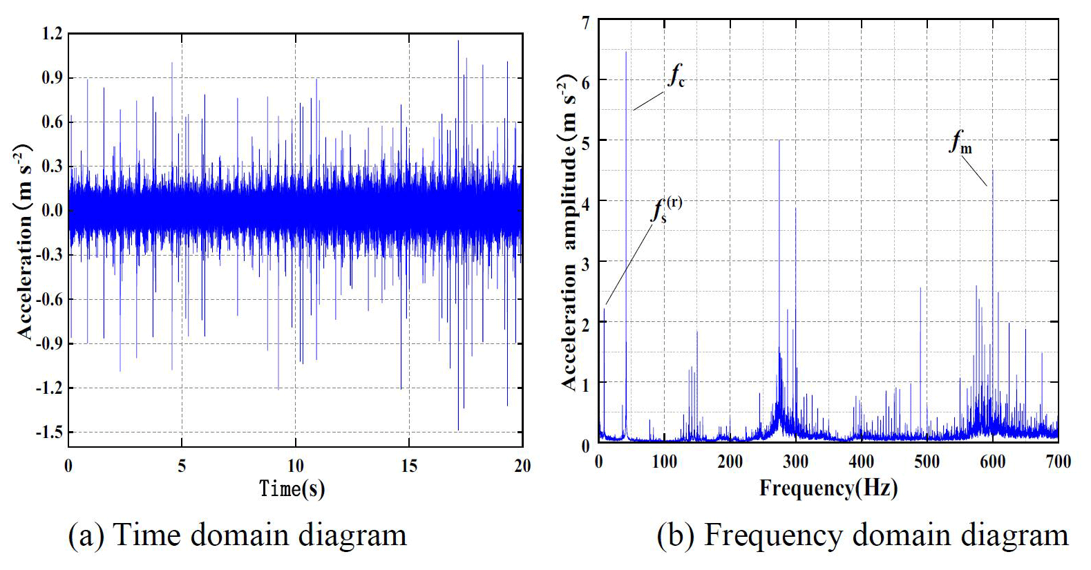
Figures 11b, 12b and 13b show that, under three input speeds, the frequency domain signal of vibration acceleration of planetary gearbox has obvious vibration peaks at three characteristic frequencies of the gearbox, which indicates that the vibration acceleration signal measured in the experiment has a good level of reliability.
The time domain signals of the vibration displacement of the planetary gearbox can be obtained by processing the time domain signals of the three groups of the gearbox vibration acceleration signals measured by the analysis software, as shown in Fig. 14. At the same time, based on the system parameters of the planetary gearbox, the theoretical spectrum diagram of the system under three input speeds is obtained through theoretical analysis.
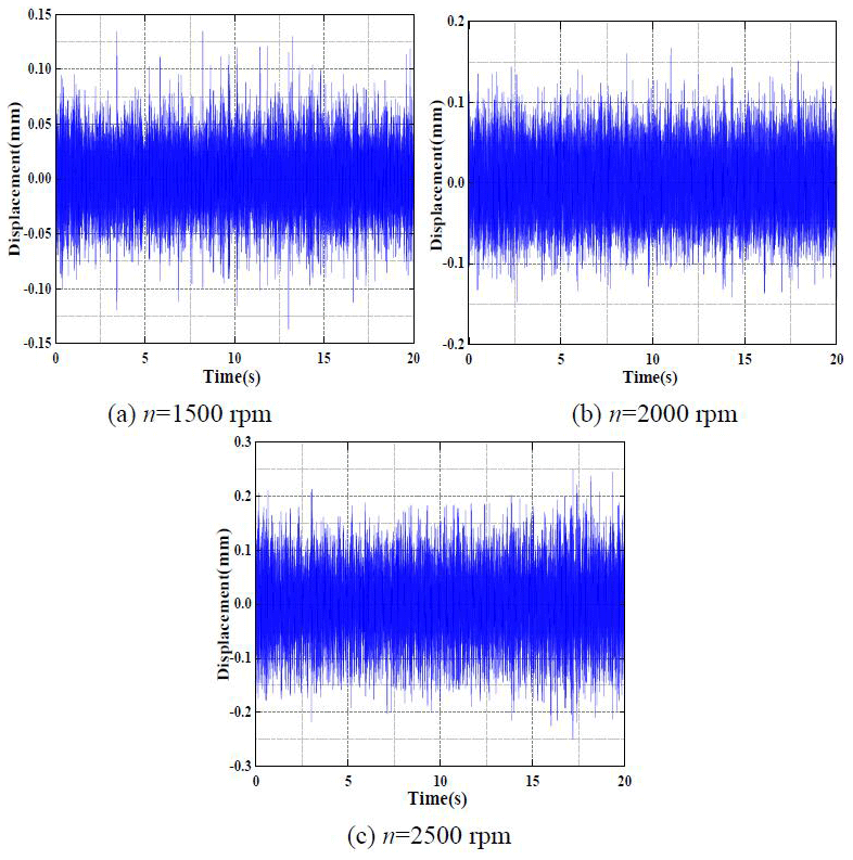
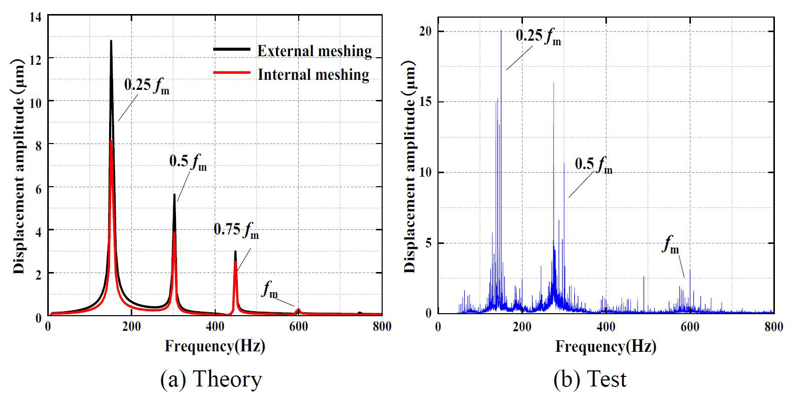
Figure 15 shows the spectrum of the theoretical and experimental displacement of the system when the input speed n=1500 rpm. The calculated meshing frequency of the system is 360 Hz at this speed. Figure 15a is the result of theoretical analysis; the black solid line is the spectrum curve of the external meshing pair under the input speed in the theoretical analysis, and the red solid line is the spectrum curve of the internal meshing pair. The analysis of the test results is shown in Fig. 15b.
Compared with Fig. 15a and b, the results show that, in the theoretical analysis, both the internal and external meshing pairs of the system produce four resonance peaks, and the peak frequency points are the same, which are, respectively, close to the system one-quarter frequency multiplication, one-half frequency multiplication, three-quarters frequency multiplication and the meshing frequency points. In addition to the above four points, the spectrum curve of the system is smooth without side frequency resonance. In the experimental analysis, the planetary gearbox also resonates near the frequency point of the period doubling, and there is also side frequency resonance near the frequency point. In addition to the resonance caused by the motor input speed, there are other forms of vibration signals in the system.


When n=1500 rpm, the corresponding frequency values of frequency multiplication response of the planetary gearbox in the theoretical analysis and experimental analysis are shown in Table 4.
Table 4Frequency multiplication response of the gearbox at n=1500 rpm.
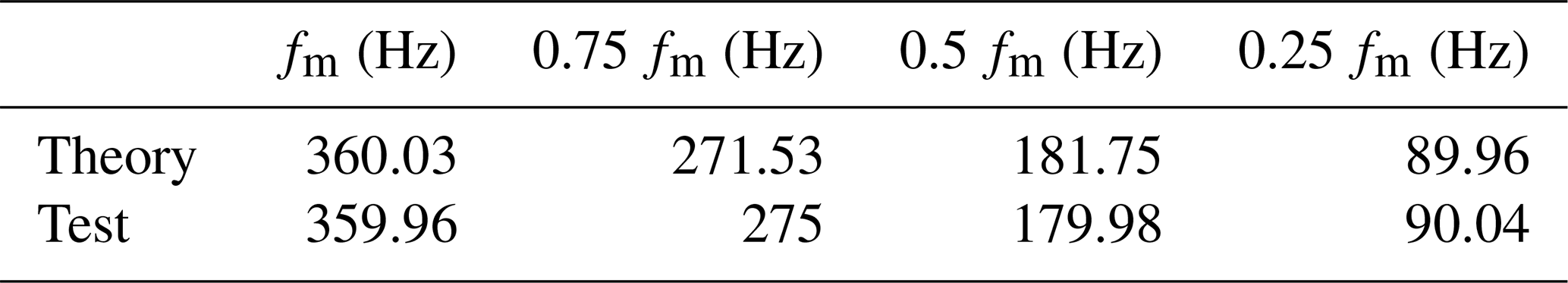
Table 5Frequency multiplication response of the gearbox at n=2000 rpm.
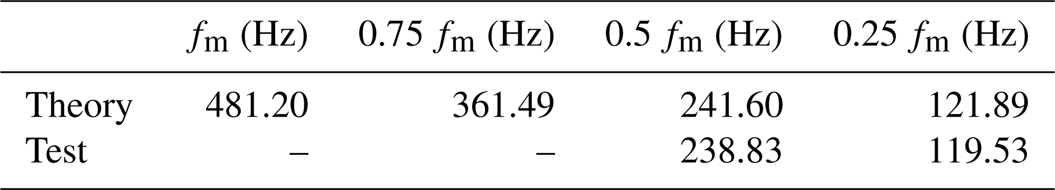
Table 6Frequency multiplication response of the gearbox at n=2500 rpm.
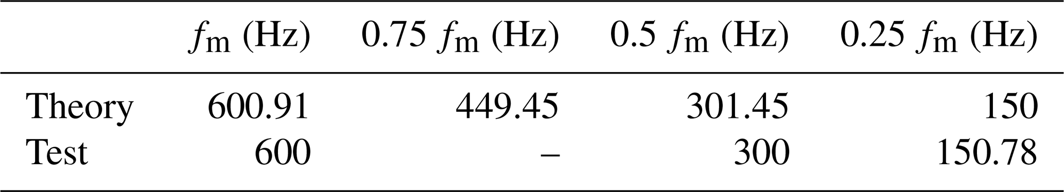
Figure 16 shows the spectrum of the theoretical and experimental displacement of the system at the input speed of n=2000 rpm. The calculated meshing frequency of the system at this speed is 480 Hz. Compared with Fig. 16a and b, the results show that the theoretical analysis spectrum produces a resonance response at four frequency points during the frequency multiplication period, while the experimental analysis spectrum only forms resonance peak at the one-quarter frequency multiplication point and one-half frequency multiplication point.
When n=2000 rpm, the corresponding frequency values of the frequency multiplication response of the planetary gearbox in theoretical and experimental analysis are shown in Table 5.
Figure 17 shows the spectrum of the theoretical and experimental displacement of the system at an input speed of n=2500 rpm. The calculated meshing frequency of the system is 600.12 Hz at this speed. Compared with Fig. 17a and b, the results show that the theoretical spectrum produces a resonance response at four frequency points during the frequency multiplication period, while the experimental spectrum only forms a resonance peak at the one-quarter frequency multiplication point, one-half frequency multiplication point and the meshing frequency.
When n=2500 rpm, the corresponding frequency values of the frequency multiplication response of the planetary gearbox in the theoretical analysis and experimental analysis are shown in Table 6.
By analyzing the spectrum diagrams under three input speeds, it can be determined that the amplitude of the test spectrum diagram is larger than that of the theoretical spectrum diagram, and the vibration signal of the test gearbox itself is more complex. Therefore, the difference in amplitude can be regarded as reasonable. At the same time, the response points of each frequency multiple of the theoretical and experimental spectrum diagram are similar, and the characteristics of vibration spectrum are the same and have similar vibration response laws. Therefore, the correctness of the analytical model established by the lumped parameter method and the effectiveness of the theoretical analysis results can be confirmed.
In order to solve the problem of the nonlinear frequency response of planetary gear transmission system, based on the lumped parameter theory, a nonlinear frequency response model of the bending torsion coupling of a planetary gear system is established by comprehensively considering the backlash, support clearance, time-varying meshing stiffness, transmission error, external periodic excitation and other factors. The Runge–Kutta numerical method is used to solve the model, and the nonlinear frequency response characteristics of the system are analyzed. Finally, the vibration test of the planetary gearbox is carried out. The conclusions are as follows:
-
With the increase in input speed, the vibration response of the planetary gear system transits from a multiple-period response to a single-period response. Under the joint action of backlash, time-varying meshing stiffness and meshing damping, the speed vibration displacement response curve of the internal and external meshing pair appears to have a nonlinear jump phenomenon and unilateral impact area, and the system presents strong nonlinear characteristics.
-
The nonlinear vibration can be effectively suppressed by decreasing the time-varying meshing stiffness or increasing the meshing damping. However, by increasing the external excitation force, the vibration response displacement of the system increases, and the nonlinear characteristics of the system remain basically unchanged. The existence of backlash is an important inducement to the nonlinear vibration of the system, but it can inhibit the vibration of the system in a certain range.
-
In the vibration test, the vibration spectrum characteristics of the vibration displacement frequency domain signal of the planetary gearbox at different speeds are similar to the simulation results, which proves the validity of the simulation analysis model and simulation results.
All data, models and code generated or used during the study appear in the article. The raw/processed data required to reproduce these findings cannot be shared at this time as the data also form part of an ongoing study.
All authors contributed to the study conception and design. The material preparation and data collection and analysis were performed by HD, YB, ZBL and XLZ. The first draft was written by HD, and all authors commented on previous versions of the paper. All authors read and approved the final paper.
The contact author has declared that neither they nor their co-authors have any competing interests.
Publisher's note: Copernicus Publications remains neutral with regard to jurisdictional claims in published maps and institutional affiliations.
This research has been funded by the National Natural Science Foundation of China (NSFC; grant no. 51705390), the Innovation Capability Support Program of Shaanxi (grant no. 2020KJXX-016), the Scientific Research Program Funded by Shaanxi Provincial Education Department Program (grant no. 20JC015), the principal foundation project of Xi'an Technological University (grant no. xgpy200201) and the Natural Science Foundation of Shaanxi Province (grant no. 2021JM-428).
This paper was edited by Hui Ma and reviewed by three anonymous referees.
Bahk, C. and Parker, R. G.: Analytical solution for the nonlinear dynamics of planetary gears, J. Comput. Nonlin. Dyn., 6, 267–274, https://doi.org/10.1115/1.4002392, 2011.
Chen, X. H., Yang, X. K., and Tian, Z. G.: Planetary gearbox dynamic modeling considering bearing clearance and sun gear tooth crack, Sensors, 21, 2638, https://doi.org/10.3390/s21082638, 2021.
Fan, Z. X., Zhu, C. C., and Song, C. S.: Dynamic analysis of planetary gear transmission system considering the flexibility of internal ring gear, IJST-T. Mech. Eng., 44, 695–706, https://doi.org/10.1007/s40997-019-00290-3, 2020.
Jian, G. X., Wang, Y. Q., Zhang, P., Li, Y. K., and Luo, H.: Analysis of lubrication performance for internal meshing gear pair considering vibration, J. Cent. South Univ., 28, 126–139, https://doi.org/10.1007/s11771-021-4591-3, 2021 (in Chinese).
Li, H. W., Liu, J., and Ma, J. L.: Effect of the radial support stiffness of the ring gear on the vibrations for a planetary gear system, J. Low Freq. Noise V. A., 39, 1024–1038, https://doi.org/10.1177/1461348419844642, 2020.
Li, S., Wu, Q. M., and Zhang, Z. Q.: Bifurcation and chaos analysis of multistage planetary gear train, Nonlinear Dynam., 75, 217–233, https://doi.org/10.1007/s11071-013-1060-z, 2014.
Li, X. and Feng, Z. P.: Vibration spectral features of planetary gearbox combined faults, Journal of Vibration and Shock, 39, 15–23, https://doi.org/10.13465/j.cnki.jvs.2020.01.003, 2020 (in Chinese).
Li, Y. G., Chen, T. N., and Wang, X. P.: Non-linear dynamics of gear pair with dynamic backlash subjected to combined internal and external periodic excitations, J. Vib. Control, 22, 1693–1703, https://doi.org/10.1177/1077546314544350, 2016.
Li, Z. X. and Peng, Z.: Nonlinear dynamic response of a multi-degree of freedom gear system dynamic model coupled with tooth surface characters: a case study on coal cutters, Nonlinear Dynam., 84, 1–16, https://doi.org/10.1007/s11071-015-2475-5, 2015.
Liu, J., Pang, R. K., and Li, H. W.: Influence of support stiffness on vibrations of a planet gear system considering ring with flexible support, J. Cent. South Univ., 27, 2280–2290, https://doi.org/10.1007/s11771-020-4449-0, 2020 (in Chinese).
Liu, Z. X., Zhang, G. H., and Zhan, S.: Study on interactions between tooth backlash and journal bearing clearance nonlinearity in spur gear pair system, Mech. Mach. Theory, 107, 229–245, https://doi.org/10.1016/j.mechmachtheory.2016.09.024, 2017.
Mao, H., Sun, Y., and Xu, T.: Numerical calculation method of meshing stiffness for the beveloid gear considering the effect of surface topography, Math. Probl. Eng., 2, 1–17, https://doi.org/10.1155/2021/8886792, 2021.
Saghafi, A. and Farshidianfar, A.: An analytical study of controlling chaotic dynamics in a spur gear system, Mech. Mach. Theory, 96, 197–191, https://doi.org/10.1016/j.mechmachtheory.2015.10.002, 2016.
Sun, T. and Hu, H. Y.: Nonlinear dynamics of a planetary gear system with multiple clearances, Mech. Mach. Theory, 38, 1371–1390, https://doi.org/10.1016/S0094-114X(03)00093-4, 2003.
Tang, X., Bao, H. Y., and Lu, F. X.: Nonlinear dynamic analysis of planetary gear train system with meshing beyond pitch point, Transactions of Nanjing University of Aeronautics and Astronautics, 37, 884–897, https://doi.org/10.16356/j.1005-1120.2020.06.006, 2020 (in Chinese).
Wang, C. L., Zhang, X. F., and Zhou, J. X.: Calculation method of dynamic stress of flexible ring gear and dynamic characteristics analysis of thin-walled ring gear of planetary gear train, J. Vib. Eng. Technol., 9, 751–766, https://doi.org/10.1007/s42417-020-00259-6, 2021.
Wang, J. G., Lv, B., and Zhao, Y. X.: Chaos and stability of spur gear transmission system for locomotive based on energy method and floquet theory, Shock Vib., 10, 5691892, https://doi.org/10.1155/2018/5691892, 2018.
Wang, W. Y., Kristina, J., and Tony, G.: Vibration analysis of planet gear bore-rim failure using enhanced planet time synchronous averaging, Eng. Fail. Anal., 117, 104942, https://doi.org/10.1016/j.engfailanal.2020.104942, 2020.
Wang, X.: Nonlinear dynamic characteristics of fixed-axis gear wear in multistage gear transmission systems, Shock Vib., 2019, 5641617, https://doi.org/10.1155/2019/5641617, 2019.
Xiang, L., Liu, S. J., and Zhang, J. H.: Nonlinear dynamic characteristics of two-stage planetary gear transmission system in wind turbine gearbox, Journal of Vibration and Shock, 39, 193–199+229, https://doi.org/10.13465/j.cnki.jvs.2020.15.026, 2020a (in Chinese).
Xiang, L., Deng, Z., and Hu, A.: Dynamical analysis of planetary gear transmission system under support stiffness effects, Int. J. Bifurcat. Chaos, 30, 577–595, https://doi.org/10.1142/S0218127420500807, 2020b.
Xiao, Z. M., Yu, L. R., and Cao, J. X.: Influence of crack fault on the dynamical characteristics of a planetary gear transmission system, Journal of Vibration and Shock, 39, 188–194, https://doi.org/10.13465/j.cnki.jvs.2020.02.026, 2020 (in Chinese).
Yang, Y., Xia, W. K., and Han, J. M.: Vibration analysis for tooth crack detection in a spur gear system with clearance nonlinearity, Int. J. Mech. Sci., 157–158, 648–661, https://doi.org/10.1016/j.ijmecsci.2019.05.012, 2019.
Zhang, Q., Li, S. L., and Zhang, Y. D.: Study on modal test and analysis of planetary transmission mechanism, IOP C. Ser. Earth Env., 632, 042002, https://doi.org/10.1088/1755-1315/632/4/042002, 2021.
Zhou, L., Wu, S. J., and Li, J.: Establishment of translational and torsional model and nonlinear dynamic characteristic analysis for 2K-H planetary gear trains, Journal of Vibration and Shock, 35, 71–76+116, https://doi.org/10.13465/j.cnki.jvs.2016.12.011, 2016 (in Chinese).
- Abstract
- Introduction
- Establishment of nonlinear frequency response model
- Establishment of nonlinear frequency response differential equation
- Example of system frequency response characteristics and parameter influence analysis
- Frequency response vibration test
- Conclusion
- Code and data availability
- Author contributions
- Competing interests
- Disclaimer
- Financial support
- Review statement
- References